Article

Modeling of Coal Mill System Used for Fault Simulation

State Key Laboratory of Alternate Electrical Power System with Renewable Energy Sources, Control and Computer Engineering College, North China Electric Power University, Beijing 102206, China
*
Author to whom correspondence should be addressed.
Energies 2020, 13(7), 1784; https://doi.org/10.3390/en13071784
Submission received: 18 March 2020 / Revised: 3 April 2020 / Accepted: 5 April 2020 / Published: 7 April 2020
(This article belongs to the Section F: Electrical Engineering)

Abstract

:
Monitoring and diagnosis of coal mill systems are critical to the security operation of power plants. The traditional data-driven fault diagnosis methods often result in low fault recognition rate or even misjudgment due to the imbalance between fault data samples and normal data samples. In order to obtain massive fault sample data effectively, based on the analysis of primary air system, grinding mechanism and energy conversion process, a dynamic model of the coal mill system which can be used for fault simulation is established. Then, according to the mechanism of various faults, three types of faults (i.e., coal interruption, coal blockage and coal self-ignition) are simulated through the modification of model parameters. The simulation shows that the dynamic characteristic of the model is consistent with the actual object, the relative error of each output variable is less than 2.53%, and the total average relative error of all outputs is about 1.2%. The model has enough accuracy and adaptability for fault simulation, and the problem of massive fault samples acquisition can be effectively solved by the proposed method.

1. Introduction

The main task of a coal mill system is to provide qualified fuel for the pulverized coal boiler. In the coal mill system, raw coal is firstly grinded into fine powder, and then dried and transmitted into the boiler by the primary air. Coal mill is the core equipment of pulverizing system, the grinding, separating, drying and transmission processes are all realized by coal mill. If the coal mill fails, the fuel supply of the boiler will not be guaranteed directly, the unit will take rapid load reduction operation, which will directly lead to furnace fire-extinguishing in serious cases [1]. Therefore, the effective monitoring and diagnosis of a coal mill system is very important for the security operation of a coal-fired power plant.
In recent years, the technology of artificial intelligence has developed rapidly, deep learning algorithm has been widely used in pattern recognition and fault diagnosis [2], such as bearing fault diagnosis [3,4], rotating machinery fault diagnosis [5], and aircraft engine health diagnosis [6]. The fault diagnosis method based on massive historical operation data has gradually become a research hotspot. It extracts data features from massive historical data through deep hierarchical architectures, then establishes the relationship between the learned features and equipment status, and judges the health status and fault type of equipment. However, for data-driven fault diagnosis method, massive fault samples are needed to establish an accurate mapping relationship between sample features and equipment status. In the massive historical database of the unit, the fault types and fault samples are not complete; moreover it is difficult to select the fault data one by one from the historical database. The deep learning algorithm cannot effectively learn the fault data features due to the lack of diversity of fault sample data and the limited sample set. Therefore, it is difficult to obtain an accurate diagnosis model for status monitoring and fault diagnosis, which seriously restricts the development of data-driven fault diagnosis method in the industrial field [7,8].
To solve the problem of acquiring massive fault data, a method used for fault data generation is proposed in this paper, by which fault data samples can be generated by the fault simulation of a coal mill system model. The core lies in constructing a model of the coal mill system that can support fault simulation. As early as in 1998, an improved dynamic model of vertical spindle roll mill was established in reference [9] in order to realize precise control of pulverized fuel flow, in which the abnormal operation conditions were also considered and simulated, but it cannot support the simulation in failure state. In reference [10], an optimal observer was designed based on the simple dynamic model, in which the estimated residual can be used for faults detection. In this model, the input coal flow was assumed to be equal of the output coal flow, and only the energy transfer process was considered. In reference [11], a roll mill model used to improve mill control for a better unit load tracking capability was established, in which the model of coal storage, powder storage, coal powder flow and the outlet temperature of mixture were taken into account, but this model does not consider the characteristic in fault state and cannot be used for fault simulation. Reference [12] proposed a nonlinear three state dynamic model of coal mill, in which the grinding relationship of coarse to fine particle was also presented. Based on the proposed model, the dynamic performance under start-up and normal condition can be predicted, and a model-based predictive control was designed for better load tracking and disturbance rejecting. In reference [13], a coal mill model used for the precise control of outlet temperature of mixture and pulverized coal flow was developed and validated, in which the action of classifier was included. Reference [14] proposed a mathematical model of coal mill to estimate the moisture of coal powder, and an optimal set value of outlet temperature based on the estimated powder moisture was given for economic operation of boiler. Inspired by the modeling of MPS (Mill Parter Ship) pulverizer, by studying the dynamic characteristic of ball mill system, a duplex inlet and outlet model was built and a multivariable control system was designed in reference [15], which was used to a rapid unit load tracking and disturbance rejecting. Based on the model proposed in reference [14], by considering the influence of raw coal moisture on the model accuracy, an improved nonlinear dynamic model of MPS mill was built in reference [16], by which the outlet coal powder flow was monitored and a new control strategy was designed to improve the control accuracy of the system’s output [17]. In reference [18], the mathematical models of static-classifier and dynamic-classifier types of pulverizers were discussed based on the energy and mass balance. Overall, in the research on the modeling of a coal mill system, it is mainly used for the optimal control or the prediction of unknown parameters. On the one hand, it improves the anti-disturbance ability of pulverizing system; on the other hand, it improves the unit load tracking ability through the precise output control of pulverizing system. However, none of the models involved above consider the dynamic characteristics of a coal mill system in the fault state, and it is impossible to be used for fault simulation.
Therefore, on the basis of previous work, in order to build a coal mill system model which can be used for fault simulation, the paper is arranged as follows: Section 2 introduces the working mechanism of coal mill system; Dynamic model derivation, model parameter identification and verification are introduced in Section 3 and Section 4 separately. In Section 5, three kinds of faults are analyzed and simulated. Section 6 is the conclusion.

2. Working Principle of a Coal Mill System

MPS medium-speed coal mill is a roll-type medium-speed coal mill designed and manufactured by Babcock, Germany. The mill is characterized by low power consumption, smooth output and long maintenance period, which is suitable for grinding hard bituminous coal. At present, this type of mill has been widely used in coal-fired power plants of China, and its structure is shown in Figure 1. The medium-speed coal mill system is mainly composed of raw coal bunker, coal feeder, coal mill, primary fan, sealing fan, hot and cold air regulating valves. The coal feeder transports the raw coal from bunker to mill for grinding. The primary air is divided into two paths after being pressurized by primary fans. One path enters the hot primary air pipe after being heated by the air preheater; the other directly enters the cold primary air pipe. After two paths are mixed, the mixed air enters the mill to complete the task of coal powder drying and transmitting. At the same time, partial cold primary air is pressurized by the sealing fan to prevent the leakage of coal powder. Inside the coal mill, the grinding part is composed of a groove type grinding plate and three convex grinding rollers. Under the action of spring force or liquid pressure, the grinding roller and the grinding plate are tightly pressed together to roll the raw coal between the grinding parts into coal powder, and the pulverized coal particles are thrown to the air ring chamber under the action of centrifugal force. The primary air blows the pulverized coal entering the air ring chamber into the coarse and fine powder separator, in which the pulverized coal with larger particles will be separated under the centrifugal force and falls back to the grinding plate for further grinding, and the pulverized coal with smaller particles will be blown into the furnace with the primary air for combustion.
In the actual operation of a coal mill system, the coal feed flow, inlet primary air flow and outlet temperature of mixture are mainly regulated, in which coal feed flow is adjusted by the rotation speed of coal feeder according to the command of the boiler; inlet primary air flow is regulated by hot air valve, and the air flow command is converted from the coal feed instruction; outlet temperature of air/powder mixture is controlled by cold air value.

3. Dynamic Model of a Coal Mill System

3.1. Primary Air System Model

The primary air system of a coal mill is mainly responsible for two tasks of coal powder drying and transmitting. The inlet primary air flow is mainly determined according to the differential pressure and the resistance along the pipeline. The resistance along the pipeline is mainly affected by the opening degree of the regulating valve. Considering the different design of the cold/hot primary air pipeline, the cold/hot primary air flow at the inlet of coal mill can be respectively expressed as:
w H = p f p i n ε H
w C = p f p i n ε C
where p f is outlet pressure of primary fan (kPa); p i n is inlet air pressure of coal mill (kPa); w H is the hot air flow (kg/s); w C is the cold air flow (kg/s); ε H and ε C are the damping coefficient of hot and cold air pipes. Here, it is assumed that the damping coefficient of primary air pipe is only related to opening degree of the regulating valve. When the opening of valve is 0, the damping coefficient is infinite, which can be fitted by the following formula:
ε H = 1 k 1 u H 2
ε C = 1 k 2 u C 2
where u H is the opening of hot air valve (%); u C is the opening of cold air valve (%); k 1 and k 2 are the undetermined parameters of model.
The inlet air pressure of coal mill is mainly determined by the outlet pressure of primary fan and the openings of regulating valves. However, when the coal blockage occurs, with the increase of the coal/powder storage in the mill, the coal powder cannot be blown out due to the internal blockage and the air flow will decrease gradually. The inlet pressure of the mill will gradually approach the outlet pressure of primary fan. Therefore, the inlet primary air pressure can be corrected by the total coal stored in the mill, considering the volume inertia of primary air in the process of pipeline transmission, it can be expressed as:
α 1 d p i n d t = ( k 3 u H + k 4 u C ) 1 M r c + M p c M max p f p i n
where M r c is the raw coal stored in the mill (kg); M p c is the pulverized coal stored in the mill (kg); M max is the maximum storage capacity of the mill (kg); α 1 is the volume inertia coefficient; k 3 and k 4 are the undetermined parameters of model.
Then, according to the conservation of mass and energy of the primary air system, the primary air flow and temperature at the inlet of the mill can be expressed as:
w i n = w H + w C
α 2 T ˙ i n = c C w C T C + c H w H T H c i n w i n T i n
where T C is the cold air temperature (°C); T H is the hot air temperature (°C); T i n is the inlet air temperature (°C); w i n is the inlet primary air flow (kg/s); α 2 is the inertia coefficient of the mixed air temperature; c C , c H , and c i n are the specific heat capacity of cold air, hot air, and mixed air (kJ/(kg·°C)), respectively, which can be approximately calculated by Equation (8):
c i = 0.0001 T i + 1.0099

3.2. Coal–Powder Storage Model

According to the mass balance of coal mill system, the amount of raw coal and coal powder stored in the mill can be expressed as follows [14]:
M ˙ r c = w r c k g r M r c
M ˙ p c = k g r M r c w p c
where w r c is the coal feed flow (kg/s); w p c is the coal powder flow at outlet (kg/s); k g r is the grinding coefficient, which is related to the grinding current when the pressure of grinding roller is constant, so the grinding coefficient can be approximately expressed as:
k g r = k 5 I b
Because the amount of raw coal and coal powder stored in the mill cannot be measured, there is no actual reference data in the model identification process. So, the dynamic characteristic of raw coal and coal powder stored in the mill can be reflected by constructing the grinding current signal, which can be expressed as follows:
I b = k 6 M r c + k 7 M p c + k 8
where I b is the grinding current of mill (A); k 5 , k 6 , k 7 and k 8 are the undetermined parameters of model.
The outlet coal powder flow indicates the carrying capacity of primary air, which is directly proportional to the differential pressure of the mill and the amount of coal powder stored in the mill [18]. However, in case of coal blockage fault, the amount of coal powder stored in the mill increases because the coal powder cannot be brought out smoothly. At the same time, the differential pressure of the mill also increases, which makes the above relationship in reference [18] unable to adapt to the fault condition. Therefore, the outlet coal powder flow of the mill can be characterized by the outlet air pressure, the inlet primary air flow and the amount of coal powder stored in the mill. The increase of the outlet air pressure and the inlet primary air flow of the mill both indicate the increase of the primary air carrying capacity. Therefore, the outlet coal powder flow of the mill can be expressed as:
w p c = k 9 p o u t M p c w i n
The flow process of primary air in the mill can be similar to the flow process of primary air in the pipeline, the characteristic of the outlet pressure of mill is similar to the outlet pressure of the air pipe, and the coal/powder stored in the mill is similar to the opening of regulating valve. When the coal/powder storage capacity reaches the upper limit, it is equivalent to the valve is fully closed, then the outlet air pressure of the mill can be expressed as:
α 3 d p o u t d t = k 10 ( 1 M r c + M p c M max ) p m i n p o u t
where p o u t is the outlet air pressure of mill (kPa); k 9 and k 10 are the undetermined parameters of model; α 3 is the inertia coefficient.

3.3. Outlet Temperature Model

According to the energy balance between the input and output of the mill, the outlet temperature of the air/powder mixture can be expressed as [17]:
α 4 ( M m t + M r c + M p c ) T ˙ o u t = Q i n Q o u t
where α 4 is the inertia coefficient of outlet temperature; Q i n is the total input energy of coal mill system (kJ), which mainly includes the heat brought in by primary air, raw coal, mill grinding and sealing air, it can be expressed as:
Q i n = c i n T i n w i n + c r c T r c w r c + k m I + k s c C T C w i n
where T r c is the temperature of raw coal (°C); c r c is the specific heat of raw coal (kJ/(kg·°C)); k m is the heat conversion coefficient, generally 0.6; k s is air leakage coefficient, generally 0.1.
Q o u t is the total output energy of coal mill system (kJ), which mainly includes the heat brought out by primary air, evaporated water, coal powder and heat loss, it can be expressed as:
Q o u t = c o u t T o u t ( 1 + k s ) w i n + c H 2 O T o u t w a r + c p c T o u t w p c + k l Q i n
where c o u t is the specific heat of outlet air (kJ/(kg·°C)); c H 2 O is the specific heat of water (kJ/(kg·°C)); w a r is evaporated water of raw coal (kg/s); c p c is the specific heat of coal powder (kJ/(kg·°C)); k l is the coefficient of heat loss, generally 0.005.
In the above formula, the specific heat of raw coal and coal powder are related to their components, which are mainly divided into two parts: the specific heat capacity of coal drying basis and the specific heat capacity of water, which can be solved by Equation (18).
c i = 1.844 × 100 θ i 100 + 4.187 × θ i 100
where c i presents the specific heat of raw coal or coal powder (kJ/(kg·°C)); θ i is the moisture content of raw coal or coal powder (%).

3.4. Coal Powder Moisture Model

The moisture in the raw coal can be divided into two parts. One part is brought out of the mill after being dried by primary air and the other part is still kept in the coal powder. Therefore, according to the mass conservation of moisture in the coal, the moisture of coal powder at the outlet of the mill can be expressed as:
( M r c + M p c ) θ ˙ p c = w r c θ r c w a r w p c θ p c
where θ r c is the moisture of raw coal (%), the test value of coal moisture researched in this paper is 13.33%; θ p c is moisture of coal powder (%); w a r is the moisture evaporated by the primary air (kg/s), it is related to the raw coal moisture, the outlet temperature of mixture and the primary air flow, which can be expressed as:
w a r = w r c θ r c ( k 11 T o u t + k 12 ) ( 1 e w i n k 13 )
In conclusion, according to the combination of primary air system model, coal/powder storage model, outlet temperature model and coal powder moisture model, the dynamic model of the coal mill system can be expressed as follows:
w i n = u H k 1 ( p f p i n ) + u C k 2 ( p f p i n ) α 1 d p i n d t = ( k 3 u H + k 4 u C ) 1 M r c + M p c M max p f p i n α 2 T ˙ i n = c C w C T C + c H w H T H c i n w i n T i n α 3 d p o u t d t = k 10 ( 1 M r c + M p c M max ) p m i n p o u t α 4 ( M m t + M r c + M p c ) T ˙ o u t = Q i n Q o u t M ˙ r c = w r c k 5 I b M r c M ˙ p c = k 5 I b M r c w p c ( M r c + M p c ) θ ˙ p c = w r c θ r c w a r w p c θ p c I b = k 6 M r c + k 7 M p c + k 8 w p c = k 9 p o u t M p c w i n w a r = w r c θ r c ( k 11 T o u t + k 12 ) ( 1 e w i n / k 13 ) Q i n = c i n T i n w i n + c r c T r c w r c + k m I b + k s c C T C w i n Q o u t = c o u t T o u t ( 1 + k s ) w i n + c H 2 O T o u t w a r + c p c T o u t w p c + k l Q i n
where the inputs of the coal mill system model are outlet pressure of primary fan ( p f ), hot air temperature ( T H ), cold air temperature ( T C ), hot air valve opening ( u H ), cold air valve opening ( u C ) and coal feed flow ( w r c ); the outputs of the coal mill system model are inlet air temperature ( T i n ), inlet air pressure of mill ( p i n ), inlet air flow ( w i n ), outlet air pressure of mill ( p o u t ) and outlet temperature of mixture ( T o u t ); intermediate variables of model are raw coal stored in mill ( M r c ), coal powder stored in mill ( M p c ), grinding current ( I b ), coal powder flow ( w p c ) and coal powder moisture ( θ p c ). α i ( i = 1 , 2 , 3 , 4 ) is the dynamic parameter and k i ( i = 1 , 2 , , 13 ) is the static parameter of the model.

4. Model Parameter Identification and Verification

4.1. Model Parameter Identification

In the process of model parameter identification, the coal mill system of 2 × 660 MW secondary reheating unit of Guodian Suqian power plant in China is taken as the research object. The established model involves many undetermined parameters, so in order to improve the model accuracy and ensure the physical meaning of each variable, each module is identified successively according to the connection relationship. First, we identify the coal/powder storage model in the mill, and then identify the primary air system model, outlet temperature model and coal powder moisture model in turn after obtaining the intermediate variable M r c and M p c . The identification process is shown in Figure 2. The fitness function used in each identification process is shown in Equations (21)–(23), and the model parameters obtained by identification are shown in Table 1.
f i t 1 = t = 0 N [ w 1 p o u t ( t ) p ^ o u t ( t ) p ^ o u t ( t ) + w 2 I b ( t ) I ^ b ( t ) I ^ b ( t ) ]
f i t 2 = t = 0 N [ w 3 w i n ( t ) w ^ i n ( t ) w ^ i n ( t ) + w 4 T i n ( t ) T ^ i n ( t ) T ^ i n ( t ) + w 5 p i n ( t ) p ^ i n ( t ) p ^ i n ( t ) ]
f i t 3 = t = 0 N T o u t ( t ) T ^ o u t ( t ) T ^ o u t ( t )
where w i ( i = 1 , 2 , , 5 ) is the weight coefficient; N is data length. The superscript ^ indicates the actual operation data at time t.

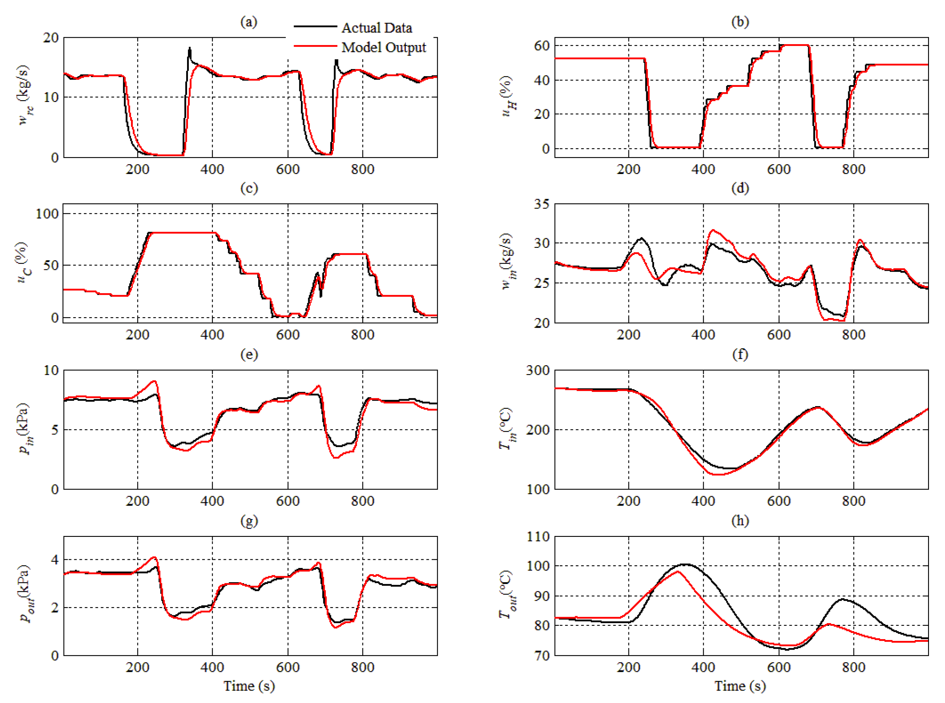
4.2. Model Validation

In order to verify the accuracy of the model, the actual operation data collected from massive historical database of Guodian Suqian power plant in China is taken as the model input, and then the difference between the model output and the actual output can be compared. The comparison curves of each variable are shown in Figure 3. Figure 3a shows the trends of each input variable of the system, in which the coal feed flow varies from 9 kg/s to 13 kg/s, and the hot air temperature and cold air temperature are 312 °C and 33 °C respectively; Figure 3b is the comparison curves of the inlet air flow, the inlet air temperature and the inlet air pressure of primary air system; Figure 3c is the comparison curves of the grinding current, the outlet temperature of mixture and the outlet air pressure of the mill. From the comparison curves, it can be seen that the dynamic characteristics of the model are basically the same as the actual in the period of 8000 s. The relative error of each variable is shown in Table 2, it can be found that the relative error of each output variable of the model is less than 2.53%, and the total average relative error of all outputs is about 1.2%, which shows the model has high simulation accuracy.

5. Typical Fault Simulation

In the massive historical database of coal mill system, the fault sample data is very limited, and it is difficult to cover all the operating conditions of the system due to the low system failure rate, which makes the fault diagnosis method based on data-driven difficult to be applied effectively. How to obtain a large number of typical fault samples is the key point to solve the fault diagnosis of coal mill. In this paper, based on the established model, the failure operation state of the system is triggered according to the failure mechanism, and massive fault samples can be collected by traversing each operation condition.
In order to ensure that the input variables are consistent with the actual operation in the fault state, the closed-loop control system is constructed with reference to the control logic and control parameters of the actual system, in which the coal feed flow, outlet pressure of primary fan, hot air temperature, cold air temperature and coal moisture are the boundary parameters; the inlet air flow is controlled by the hot air valve, and outlet temperature of mixture is regulated by the cold air valve. By modifying the boundary conditions and model parameters, the fault operation state of the system can be triggered. In this paper, three kinds of common faults are mainly discussed, i.e., coal interruption, coal blockage and coal self-ignition.

5.1. Simulation of of Coal Interruption

The coal interruption fault is often caused by the blockage of coal bunker or the coal feeder failure. When the coal interruption occurs, the coal feed flow into the mill will suddenly reduce to 0. Therefore, it is only to step down the signal of coal feed flow to 0 to realize the simulation of coal interruption. In order to ensure the diversity of fault data samples, it only needs to traverse the boundary parameters in the normal fluctuation range and repeat the coal interruption simulation process.
Due to the frequent occurrence of coal interruption in actual operation, we select a group of actual fault data to compare with the simulation data to verify the effectiveness of the fault simulation. Figure 4 shows the operation curve of the coal mill with two consecutive coal interruption faults in 1000 s, the input variables of the model are the actual coal feed flow, the openings of hot air valve and cold air valve. When the coal interruption fault occurs, coal powder flow needed to be dried reduces to 0, and the outlet temperature of the mill will rise rapidly. In order to ensure the stability of the outlet temperature, the regulating valve of cold air will open quickly; in the regulating process of cold air valve, the hot air valve will close quickly to ensure the stability of inlet primary air flow.
With the alternation regulating of cold and hot air valves, the inlet air pressure, the outlet air pressure and inlet air temperature vibrate. It can be seen from Figure 4 that the coal interruption characteristics simulated by the model is almost the same as the actual coal interruption fault, and the simulated output only has a small deviation, which shows that the model established in this paper has a high simulation accuracy and adaptability, and the simulated data can be used as the coal interruption fault samples.

5.2. Simulation of Coal Blockage

Coal blockage can be caused by many reasons, such as low primary air flow, excess coal feed flow, decrease of grinding capacity or high coal powder moisture, which cause that the raw coal in the mill cannot be ground immediately or the coal powder in the mill cannot be brought out quickly. However, no matter what causes the coal blockage, it will lead to the increase of coal/powder storage in the mill and the increase of flow resistance. The inlet primary air flow and powder carrying capacity will decrease.
In this paper, coal blockage fault is simulated by decreasing the grinding capacity of the mill. The variable kgr of the model is the grinding coefficient, which represents the ability of the mill to grind raw coal into coal powder. Under normal operation conditions, the grinding coefficient is related to the grinding roller pressure and grinding current. In the fault simulation process, the grinding coefficient is multiplied by the attenuation coefficient λ (λ decreases from 1 to 0 at a certain rate when the coal blockage fault is triggered), the upper limit of coal/powder storage in the mill is 500 kg, and the upper limit of grinding current is 70 A. The simulation curve is shown in Figure 5. The grinding coefficient begins to decline at 40 s. With the decrease of grinding capacity, the amount of raw coal in the mill increases rapidly, this results in the increase of flow resistance and the decrease of outlet pressure. Since the primary air cannot pass through the mill smoothly, the inlet air pressure rises and the primary air flow decreases. Due to the decrease of primary air flow and the increase of coal storage, the outlet temperature of mixture is gradually reduced, and the cold/hot air valve are automatically adjusted to maintain the primary air flow and outlet temperature; until the amount of coal/powder storage reaches its upper limit, the primary air channel is completely blocked, and the primary air flow is reduced to 0. Based on the above analysis, the simulation experiment conforms to the fault characteristics of coal blockage, so the simulated data in Figure 5 can be taken as the fault data sample.

5.3. Simulation of Coal Self-Ignition

For the coal with higher volatile content, if the inlet air temperature is too high, the volatile content in the raw coal will be separated out and burned, which will cause the spontaneous combustion of coal powder. When the coal self-ignition fault occurred, the outlet air temperature of mixture will rise greatly, which will endanger the safety operation of the system. In the simulation of coal self-ignition, the coal powder wpc is divided into two parts, one part is brought into the furnace by primary air for combustion, and the other part is self-ignition in the mill. Therefore, the outlet temperature model needs to be modified in the simulation of coal self-ignition fault. In which, the heat generated by self-ignition should be added into the total input energy, and then the Equation (16) is revised as follows:
Q i n = c i n T i n w i n + c r c T r c w r c + k m I + k s c C T C w i n + ϕ w p c q n e t , a r
The total output energy taken away by the pulverized coal is corrected as follows:
Q o u t = c o u t T o u t ( 1 + k s ) w i n + c H 2 O T o u t w a r + c p c T o u t ( 1 ϕ ) w p c + k l Q i n
where ϕ is the proportion coefficient of self-ignition; q n e t , a r is the net calorific value of raw coal (kJ/kg).
Figure 6 is the simulation curve of coal self-ignition fault. The fault is triggered at 20 s, the outlet temperature of mixture rises rapidly. At this time, in order to maintain the stability of the outlet temperature and primary air flow, the cold air valve is opened quickly and the hot air valve is closed rapidly, which causes the fluctuation of air pressure at the inlet and outlet of the coal mill. In the case of coal self-ignition, even if the hot air valve is closed rapidly, the outlet temperature of mixture cannot be controlled effectively. Through the above analysis, the simulation experiment basically conforms to the fault characteristics of coal self-ignition, so the simulated data in Figure 6 can be used as the fault sample of coal self-ignition.

6. Conclusions

In order to solve the problem of insufficient fault data samples in the data-driven fault diagnosis method of coal mill system, this paper constructs a dynamic model of the coal mill system and proposes a fault sample acquisition method. Based on the established model, massive fault samples can be effectively obtained by fault simulation. From the comparison curves of model verification and fault simulation, it can be seen that the model established in this paper has high simulation accuracy and adaptability to different working conditions, the relative error of each output variable is less than 2.53%, and the total average relative error of all outputs is about 1.2%; the model can realize the fault simulation of coal interruption, coal blockage and coal self-ignition, which effectively solves the problem of obtaining typical fault samples.

Author Contributions

Conceptualization, Y.H. and D.Z.; data curation, B.P. and Y.G.; formal analysis, Y.H.; funding acquisition, Y.H.; investigation, Y.H.; methodology, Y.H.; project administration, Y.H.; resources, Y.H.; software, Y.H. and D.Z.; supervision, Y.H. and Y.N.; validation, Y.H. and Y.N.; visualization, Y.H. and B.P.; writing—original draft, Y.H.; writing—review and editing, Y.H. and Y.G. All authors have read and agreed to the published version of the manuscript.

Funding

This paper is supported by National Natural Science Foundation of China (51806063) and the China Postdoctoral Science Foundation (2018 M641292).

Conflicts of Interest

The authors declare no conflict of interest.

References

  1. Agrawal, V.; Panigrahi, B.; Subbarao, P. Review of control and fault diagnosis methods applied to coal mills. J. Process Control 2015, 32, 138–153. [Google Scholar] [CrossRef]
  2. Lei, Y.; Yang, B.; Jiang, X.; Jia, F.; Li, N.; Nandi, A.K. Applications of machine learning to machine fault diagnosis: A review and roadmap. Mech. Syst. Signal Process. 2020, 138, 106587. [Google Scholar] [CrossRef]
  3. Chen, Z.; Mauricio, A.; Li, W.; Gryllias, K. A deep learning method for bearing fault diagnosis based on Cyclic Spectral Coherence and Convolutional Neural Networks. Mech. Syst. Signal Process. 2020, 140, 106683. [Google Scholar] [CrossRef]
  4. Guo, X.; Chen, L.; Shen, C. Hierarchical adaptive deep convolution neural network and its application to bearing fault diagnosis. Measurement 2016, 93, 490–502. [Google Scholar] [CrossRef]
  5. Qi, Y.; Shen, C.; Wang, D.; Shi, J.; Jiang, X.; Zhu, Z. Stacked Sparse Autoencoder-Based Deep Network for Fault Diagnosis of Rotating Machinery. IEEE Access 2017, 5, 15066–15079. [Google Scholar] [CrossRef]
  6. Tamilselvan, P.; Wang, P. Failure diagnosis using deep belief learning based health state classification. Reliab. Eng. Syst. Saf. 2013, 115, 124–135. [Google Scholar] [CrossRef]
  7. Yang, B.; Lei, Y.; Jia, F.; Xing, S. An intelligent fault diagnosis approach based on transfer learning from laboratory bearings to locomotive bearings. Mech. Syst. Signal Process. 2019, 122, 692–706. [Google Scholar] [CrossRef]
  8. Guo, L.; Lei, Y.; Xing, S.; Yan, T.; Li, N. Deep Convolutional Transfer Learning Network: A New Method for Intelligent Fault Diagnosis of Machines with Unlabeled Data. IEEE Trans. Ind. Electron. 2018, 66, 7316–7325. [Google Scholar] [CrossRef]
  9. Fan, G.; Rees, N.; Parker, D. Analysis of coal Mill Dynamic Characteristics under Normal and Abnormal Operating Conditions. IFAC Proc. Vol. 1997, 30, 451–457. [Google Scholar] [CrossRef]
  10. Odgaard, P.F.; Mataji, B. Fault detection in coal mills used in power plants. IFAC Proc. Vol. 2006, 39, 177–182. [Google Scholar] [CrossRef]
  11. Niemczyk, P.; Bendtsen, J.D.; Ravn, A.P.; Andersen, P.; Pedersen, T.S. Derivation and validation of a coal mill model for control. Control Eng. Pract. 2012, 20, 519–530. [Google Scholar] [CrossRef]
  12. Cortinovis, A.; Mercangöz, M.; Mathur, T.; Poland, J.; Blaumann, M. Nonlinear coal mill modeling and its application to model predictive control. Control Eng. Pract. 2013, 21, 308–320. [Google Scholar] [CrossRef]
  13. Pradeebha, P.; Pappa, N.; Vasanthi, D.; Parameswaran, P.; Natarajan, P.; Vasanthi, D. Modeling and Control of Coal Mill. IFAC Proc. Vol. 2013, 46, 797–802. [Google Scholar] [CrossRef] [Green Version]
  14. Zeng, D.L.; Hu, Y.; Gao, S.; Liu, J.Z. Modelling and control of pulverizing system considering coal moisture. Energy 2015, 80, 55–63. [Google Scholar] [CrossRef]
  15. Zeng, D.; Wang, Y.; Gao, S.; Liu, J. Modeling and control of ball mill system considering coal moisture. Measurement 2016, 90, 43–51. [Google Scholar] [CrossRef]
  16. Gao, Y.; Zeng, D.; Liu, J. Modeling of a medium speed coal mill. Powder Technol. 2017, 318, 214–223. [Google Scholar] [CrossRef]
  17. Gao, Y.; Zeng, D.; Liu, J.; Jian, Y. Optimization control of a pulverizing system on the basis of the estimation of the outlet coal powder flow of a coal mill. Control Eng. Pract. 2017, 63, 69–80. [Google Scholar] [CrossRef]
  18. Bhatt, D.; Dadiala, V.; Barve, J. Industrial Coal Pulverizer Model Simulation and Parametric Investigation. IFAC PapersOnLine 2018, 51, 115–120. [Google Scholar] [CrossRef]
Figure 1. The structure of MPS medium-speed coal mill system.
Energies 13 01784 g001
Figure 2. The identification process of model parameters.
Energies 13 01784 g002
Figure 3. Comparison curves of each variable. (a) Trends of each input variable of the mill system. (b) Comparison curves of inlet air flow, temperature and pressure of primary air system (c) Comparison curves of grinding current, outlet air temperature and pressure of the mill.
Energies 13 01784 g003aEnergies 13 01784 g003b
Figure 4. Simulation of coal interruption.
Energies 13 01784 g004
Figure 5. Simulation of coal blockage.
Energies 13 01784 g005
Figure 6. Simulation of coal self-ignition.
Energies 13 01784 g006
Table 1. Model parameter identification results.
k1 = 575.32k2 = 110.75k3 = 1.2001k4 = 0.3045k5 = 0.0095k6 = 0.4332
k7 = 0.3746k8 = 22.139k9 = 0.0075k10 = 0.4704k11 = 0.0563k12 = −3.3664
k13 = 28.155α1 = 15.269α2 = 210.62α3 = 8.1275α4 = 19.039
Table 2. The relative error between actual output and model output.
VariableswinTinpinIbpoutTout
Relative Error (%)1.090.971.450.772.530.39

