Abstract
Fault tree analysis (FTA) is frequently applied to deductively evaluate the safety systems of complex engineering systems such as chemical industries or nuclear facilities. To perform this analysis, generic data are commonly used due to the limitation of historical failure data of the system being evaluated. However, generic data have a degree of uncertainty and hence cannot represent the system’s actual performance. In addition, generic data are not applicable to older components due to the aging process, which obviously degrades the reliability of those components. To deal with this limitation, another safety analysis method, called fuzzy fault tree analysis (FFTA), has been proposed. The purpose of this study is to apply FFTA to evaluate the performance of the primary cooling systems of G.A. Siwabessy Multipurpose Reactor (RSG-GAS). RSG-GAS is a research reactor, which belongs to the National Nuclear Energy Agency of Indonesia (BATAN). Expert justifications were used to evaluate the failure occurrences of basic events in the primary cooling system of the RSG–GAS through questionnaires. The assessment by experts is in the form of qualitative data, which are then converted into quantitative data by applying FFTA. Then, the top event probability generated from FFTA was applied to calculate the event probability using event tree analysis (ETA). It was obtained that the highest event probability was 4.304 × 10⁻⁸/year. Since it complies with The International Atomic Energy Agency (IAEA) specified core damage frequency (CDF) limit, i.e., not greater than 10−5/year of reactor operation, the reactor is safe to operate.
1. Introduction
The risk assessment can be performed both qualitatively and quantitatively [1,2]. However, the quantitative one is often discussed in the literature. Monte Carlo simulation, event tree analysis (ETA), fault tree analysis (FTA), and failure mode and effect analysis (FMEA) are commonly used methods in quantitative risk analysis [3]. These methods have been used in many applications, such as the risk assessment of gas pipeline leakage using ETA [4], risk evaluation by FMEA of a supercritical water gasification system [5], FTA for cybersecurity risk analysis [6], and health risk assessment using Monte Carlo approach [7].
From these various methods, FTA is widely used as an analytical method in probabilistic safety assessments (PSAs). It is a deductive failure analysis that focuses on one particular undesired event and provides a method for determining causes of this event. The undesired event constitutes the top event in a fault tree diagram constructed for the system and generally consists of a complete or catastrophic failure. By using the basic operations of union, intersection, and complementation, Boolean algebra allows us to express events in terms of other basic events. In fault tree applications, a system failure can be expressed in terms of basic component failures by translating the fault tree to equivalent Boolean equations [8].
As a quantitative technique for safety assessment, FTA relies heavily on statistical approaches, which require high-quality data [3]. In conventional FTA, basic events are represented by probabilities (crisp numbers). FTA assumes that the exact probabilities of events are given, and sufficient failure data are available. However, many modern systems are highly reliable, and thus, it is often very difficult to obtain sufficient statistical data to estimate precise failure rates or failure probabilities [9]. If no data are available, a quantitative risk assessment would not be possible [3].
Due to limited data, some studies use generic data when applying FTA, including the application of FTA in a nuclear research reactor. Aneziris et al. applied the FTA method using generic data in the GRR-1 (the Greek Research Reactor) [10]. Barati and Setayeshi also report the use of the FTA method with generic data to determine the total frequency of core damage accidents in the Tehran Research Reactor [11].
However, using generic data increases the uncertainty value of the PSA result [12]. Generic data are not applicable to old components because the reliability of old components is greatly affected by the aging process [13]. Moreover, the inaccuracy associated with system models due to human error is difficult to manage solely through conventional probabilistic reliability theory [9].
In 1965, Lotfi A. Zadeh considered the common way humans use adjectives and recommended that we amend the characteristic function to allow for values that fall in the interval between zero and one [14]. This is stated as the fuzzy set theory.
The application of fuzzy set theory enables qualitative data to be modeled mathematically. Qualitative judgments by experts in linguistic terms are converted to quantitative form by applying fuzzy concepts. A fuzzy set allows the gradation of membership for an element of the universal set. As a result of this, modeling based on fuzzy arithmetic is expected to express the situation more realistically [15].
Onisawa used fuzzy set theory to complement conventional reliability theory [16]. After this, many researchers developed a fuzzy method. Fuzzy fault tree analysis (FFTA) was developed to address the limitations of FTA methods. Fuzzy methods may be the only methods that can be used when the availability of the quantitative information is limited or insufficient [17,18,19].
FFTA has been widely used in many studies of various systems, such as to evaluate the failure probability of an oil and gas transmission system in a study by Yuhua and Datao [20]. FFTA was carried out by Tyagi, Pandey, and Kumar in a reliability analysis of an electric power transformer [21]. Rajakarunakaran et al. applied FFTA for the risk evaluation of a liquid petroleum gas refueling station [9]. FFTA has also been used for patient safety risk modeling in healthcare by Komal [22]. Cheliyan and Bhattacharyya used FFTA to analyze the leakage of oil and gas in a subsea production system [23]. It has also been used to evaluate nuclear power plants by Purba [24]. The application of FFTA in PSA of the nuclear power plant has been conducted and reported as well [13,24,25,26,27,28]. However, its application in the nuclear research reactor has not been reported. Moreover, the International Atomic Energy Agency (IAEA) recommends using probabilistic safety assessment (PSA) for analyzing risks associated with the operation of nuclear facilities through the issuance of the IAEA-TECDOC-1200 entitled “Application of probabilistic safety assessment, PSA, for nuclear power plants” [29] and TECDOC-400 entitled “Probabilistic Safety Assessment for Research Reactors” [30]. PSAs are performed using a logical and systematic approach to realistically assess the performance of equipment and personnel of the system being evaluated. PSA is a useful tool for safety management, and its usage can increase safety levels by providing information that is not available from the evaluation of a limited set of design-based events [29]. Therefore, this study can provide a reference on the application of PSA with fuzzy approach in a nuclear research reactor.
The national nuclear energy agency of Indonesia (BATAN) has operated three research reactors. One of those is the multipurpose reactor G.A. Siwabessy (RSG-GAS), which is located in Serpong, West Java. RSG-GAS is an open pool reactor, which is cooled and moderated by water. The reactor is designed for a thermal output of 30 MW and a peak value of thermal flux in the central irradiation position (CIP) of 5.38 × 10¹⁴ n/cm2/s [31]. Figure 1 describes the reactor building.
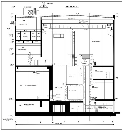
Figure 1.
Reactor building cross-section [31].
Since our study is limited to the primary cooling system of RSG-GAS, firstly we have to consider its condition. The RSG-GAS primary cooling systems remove heat from the core and reflector. Based on the Safety Analysis Report compiled by PRSG (2017), the RSG-GAS primary cooling system components consist of primary pumps and heat exchangers located within the primary cell of the reactor building [31]. These components are connected to the reactor pool and the core reactor using a pipe to form a closed circuit. The primary cooling system is also equipped with process instrumentation consisting of water-level indicators, temperature indicators, pressure indicators, and speed indicators at each primary pump.
The RSG-GAS primary cooling system has 3 pumps [31]. During the normal operation process, 2 pumps are used in parallel and 1 pump is used as a backup. The pump parts that intersect with the primary cooler are made of stainless steel. The primary pump functions to drain the primary cooling water.
The primary cooling system has 2 (two) heat exchangers that work in parallel [31]. This tool serves to move the heat generated in the primary system into the secondary cooling water. Secondary water flows through the pipes and primary cooling water flows around the pipes on the side of the cell in the opposite direction.
The primary coolant main pipe is designed to be able to withstand seismic loads. Each inlet channel and primary coolant outlet is equipped with two isolation valves located in the valve chamber. These valves work redundantly [31].
The RSG-GAS was constructed in 1983 and reached its first criticality on 27 March 1987. Meanwhile, the first operation in the full power of 30 MW was reached in March 1992. RSG-GAS has been operated for more than 30 years; hence, it experiences the aging process [32]. Tyas performed a safety analysis of the primary cooling system of RSG-GAS using hazard identification (HAZID), hazard and operability analysis (HAZOP), fault tree analysis (FTA), and event tree analysis (ETA) by utilizing generic data [33]. Hence, the aging process experienced by RSG-GAS was still not considered in the study. Consequently, the utilization of generic data taken from various sources cannot be avoided. Consequently, the results of the analysis do not fully describe the real performance of the safety system being investigated.
The purpose of this study is to propose the FFTA method to evaluate the performance of the safety systems of RSG-GAS, which do not always have sufficient historical failure data to statistically assess their component reliabilities. To confirm its applicability, the primary cooling system of the RSG-GAS is evaluated using the proposed method. This study offers two main advantages: (1) experts, who have experiences and knowledge in the construction and operation of the RSG-GAS, can provide their qualitative judgment on the reliability of the safety system related components, which do not always have sufficient historical failure data, and (2) uncertainties within the experts’ judgments can be captured through the implementation of triangular fuzzy numbers to quantitatively represent those experts’ qualitative judgments.
2. Methods
The research procedure is accomplished in six stages, as shown in Figure 2. In this case, the information about the fault tree and basic events of the system being evaluated, the RSG-GAS primary cooling system must be gathered before Stage 1 begins.
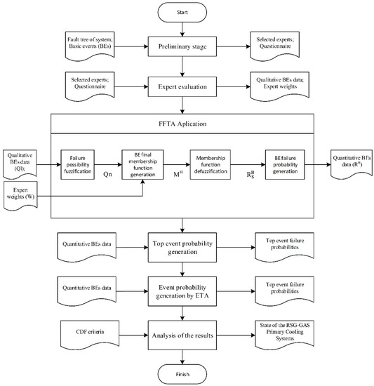
Figure 2.
Research procedure.
2.1. Stage 1: Preliminaries
This step consists of qualitative probability assessment questionnaire creation and expert selection. The questionnaires were compiled based on the fault tree and basic events data of the RSG-GAS primary cooling system. They contain the personnel data of the experts and questions about basic event failure probability for the RSG-GAS primary cooling system. The experts involved in the assessment process had to be selected properly. The expert selection was carried out by applying the methods that had been described by Kumaraningrum et al. [34]. The result of this stage is the questionnaire to be used in the assessment process and also the selected experts as the respondents.
2.2. Stage 2: Expert Evaluation
The selected experts provide an evaluation of basic events through questionnaires. The weighting of experts (1) from 0 to 1 was conducted to correlate experts’ competence with their judgments [24]. This weighting was based on their professional positions, the length of time they had worked on the system being evaluated, their educational level, and contribution to the design, construction, and/or commissioning of the reactor, as described in Table 1.

Table 1.
Experts weighting [34]. RSG-GAS: G.A. Siwabessy Multipurpose Reactor.
Table 1 represents the grading of experts. Each expert was assessed concerning the 5 criteria listed in Table 1. If an expert has a professional position as head of the division, then for the first criterion, he gets a score of 5. The same assessment is carried out for criteria 2 to 5 for each expert.
From this stage, we obtained the qualitative data for basic events and expert weights (W) as an input for the next stage.
Expert justifications, which are expressed as qualitative judgments, were collected to assess the failure possibility of basic events, and the membership functions of fuzzy numbers were used to convert those qualitative judgments into quantitative data. For example, if an expert assessed a basic event with ‘very low failure possibilities (VL)’, this means that this basic event failure probability is predicted to be less than 10−8 and very unlikely to become failures. Seven possible qualitative failures that have been set out are listed in Table 2.
Table 2.
Basic event likelihood values [28].
The result of an assessment by experts generates the matrix of basic event qualitative data (Ql). The qualitative data are in linguistic terms, such as very low, low, reasonably low, moderate, reasonably high, and very high. A Ql example is shown in Equation (2).
2.3. Stage 3: FFTA Application
2.3.1. Failure Possibility Fuzzification
The objective of this step is to generate matrix Qn as in Equation (3) from matrix Ql (2), with being the ith failure possibility of the basic event bl evaluated by the expert en. The Qn matrix is quantitative data in accordance with qualitative data from matrix Ql.
To convert qualitative data into fuzzy numbers, a triangular fuzzy number is utilized for representing the probabilities. A triangular fuzzy number is a fuzzy number represented with 3 points (al, a and au), as illustrated in Figure 3. According to Bector and Chandra (2005), a fuzzy number A is called a triangular fuzzy number (TFN) if its membership function µA is given by Equation (4) [15].
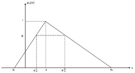
Figure 3.
Triangular fuzzy number [15].
Purba (2014) proposed the membership functions of triangular fuzzy numbers, from seven basic event failure possibilities in Table 2, which were mathematically given in Equations (5)–(11) [24]. If an expert gives a failure probability assessment of a basic event as ‘low’ in the Ql matrix, then the Qn matrix will be (0.07, 0.13, 0.19).
2.3.2. Basic Event Final Membership Function Generation
The purpose of this stage is to generate the vector MB, as shown in Equation (12). MB is the result of the multiplication of Qn in Equation (3) with the expert weights, W, as shown in Equation (1) [24].
2.3.3. Membership Function Defuzzification
At the defuzzification stage, the vector shown in Equation (13) is generated. is a vector of basic event failure probabilities produced by the decoding membership function using the area defuzzification technique (ADT) [24]. ADT is a technique for defuzzifying fuzzy numbers into single values. Figure 4 explained more about ADT. If à = (a, b, c, d) is a normal trapezoidal fuzzy number, which then becomes a normal triangle fuzzy number because of b = c, then ADT is calculated using Equation (14).
where
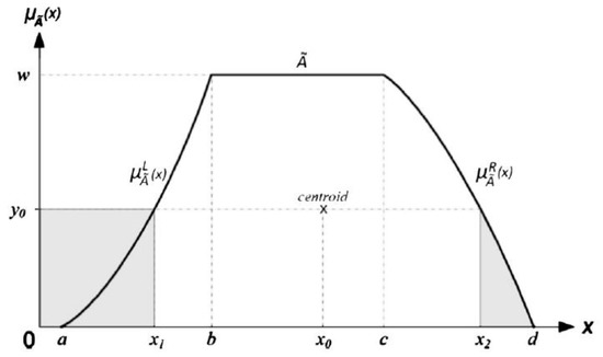
Figure 4.
Area defuzzification technique [24].
2.3.4. Basic Event Failure Probability Generation
In 1988, Onisawa explained the concept of ‘error possibility’ instead of the error rate in human reliability and its application in FTA [35]. Onisawa’s proposed logarithmic function is describes in Equation (15) to fit the very small error possibility.
where e is analogous to the failure possibility score, Em is the fuzzy failure rate, and K is a constant with a value of 0.435.
By inserting vector into Onisawa’s logarithmic function in Equation (15), a vector of failure probabilities ( is generated in Equation (16). The result of this stage is failure probabilities that are similar to the failure probabilities of historical failure data [24].
2.4. Stage 4: Top Event Probability Generation
By applying failure probabilities that were generated at Stage 3, we can calculate the top event probability. The basic event values obtained from the calculation with the fuzzy approach are used as inputs in the calculation of the probability of failure of the top event, which is done using Boolean algebra. The failure probability of an input event arising from two or more independent input events combined by a Boolean OR-gate is calculated using Equation (17), and that of an input event arising from events combined by a Boolean AND-gate is calculated using Equation (18).
where P(Ai) is the failure probability of the input event Ai and n is the number of input events at the Boolean gate [36].
2.5. Stage 5: Risk Analysis by ETA
Risk analysis in the primary cooling system was performed by ETA. The event tree diagram was developed. The incidence scenario of available safety systems was based on postulated initiating internal events obtained from the results of risk identification in the RSG-GAS primary cooling system. Failure event probability was determined for the initial event and every pivotal event. Then, the risk value was calculated for each sequence in the event tree diagram. The consequence of every sequence was determined.
2.6. Stage 6: Analysis of Results
The results of calculations with ETA are compared with acceptance criteria. From this, the condition of the RSG-GAS in terms of the reliability aspects of its primary cooling systems can be seen.
3. Results and Discussion
3.1. Preliminaries Stage
A fault tree for the primary cooling system of RSG-GAS was developed by Tyas, and it is listed in the Appendix A [33]. Eight fault trees describe the possible failure of the primary cooling system of RSG-GAS, i.e., (1) failure of the reactor scram activated by the pool water level signal, (2) failure of the reactor scram activated by the mass flow rate signal, (3) failure of the reactor scram activated by the outlet temperature signal of the primary heat exchanger, (4) failure of the reactor scram activated by the position signal of the primary isolation valve, (5) failure of secondary system isolation, (6) failure of primary system isolation, (7) failure of the primary cooler natural circulation, and (8) failure of pool cooling. Based on these fault trees, there are 23 basic events (B1–B23) underlying the occurrence of a failure in the primary cooling system of the RSG-GAS. The basic events are summarized in Table 3.
Table 3.
Basic events data of the RSG-GAS primary cooling system [33].
Questionnaires were designed as a tool of assessment for the experts on the failure probability for basic events identified in Table 3. Each expert answers the question, “What is the failure possibility of each basic event (B1 to B23)?” by selecting the answer as a form of linguistic qualitative assessment (very low/VL, low/L, reasonably low/RL, moderate/M, reasonably high/RH, high/H, or very high/H).
The experts who are involved in the assessment process were selected by using methods that have been used and described by Kumaraningrum et al. [34]. This paper describes the selection of experts as correspondents in the assessment through the development of a personnel involvement matrix on risk factors. Through the implementation of the proposed approach, 5 groups of experts were selected. The 5 groups consisted of (1) the head of division (reactor maintenance division, reactor operation division, and occupational and operation safety division); (2) the head of subdivision (mechanical system subdivision, electrical system subdivision, instrumentation, control subdivision, operation reactor subdivision, and operation safety subdivision); (3) the supervisor of the reactor and the supervisor of maintenance; (4) the operator of the reactor and the maintenance technician; and (5) the radiation protection officer and the staff of the operation safety subdivision.
3.2. Expert Evaluation
Seven experts have been confirmed to be enough and are a reasonable number for fault tree analysis by fuzzy approach in the nuclear reactor [24,28]. There were 9 experts (E1 to E9), representing each group selected, who provided an evaluation of the basic events. Hence, wider views from the personnel related to the reactor utilization could be collected. The results of the experts’ judgment are expressed as the Ql matrix (19) and an expert’s weighting (W), as shown in Table 4.
Table 4.
Experts weighting.
Each expert has their respective weighting factor, although some experts have the same value as other experts, ranging from 0.070707071 to 0.141414141. The greater value of the weighting factor indicates that the expert is more credible.
The Ql matrix is a matrix containing the results of the experts’ assessments. From this matrix, we can see that the results of the evaluation from expert number 1 (E1) are in the first column, the results of E2 are in the second column, and so on.
3.3. FFTA Application
The failure possibility fuzzification stage produces the Qn matrix shown in Equation (20) of the Ql matrix shown in Equation (19). The basic event final membership function generation stage produces the MB matrix by multiplying the Qn matrix with W. From this multiplication result, we get the values of a, b, and d, which are the final membership functions of the basic events. For example, the probabilities for basic events B1, B20, and B23 are generated as follows:
The result of the membership function defuzzification stage is the vector, which is calculated by Equations (15) and (16). Then, the result is used as the input at the basic event failure generation stage. Table 5 summarizes the failure probabilities generated by the FFTA application for all the basic events mentioned in Table 3.
Table 5.
Data generated by the fuzzy fault tree analysis (FFTA) application.
3.4. Top Event Probability Generation
The probability of a top event is calculated by Boolean algebra. The failure probability of the basic events, obtained from the fuzzy calculations (Table 5), is used. The result of the top event probability calculation is summarized in Table 6. The top event probability generation is described as follows.
Table 6.
The probability of the top event.
The repeated events and non-minimal cut sets must be simplified by the concept of minimal cut set, before the calculation of the top event probability [37]. In this way, a reliable FTA result can be produced. A minimal cut set is a cut set that has been reduced into the minimum number of fault events [37].
Following the idempotent law of Boolean algebra, the fault tree of reactor scram activated by pool water level signal (Fault tree 1, FT-1) is simplified in Figure 5. Based on the fault tree simplification of FT-1, the top event probability of FT-1 is calculated using Equation (17).
Figure 5.
Simplified of FT-1.
Using the same method as in the FT-1 calculation (26), the top event probability of a reactor scram activated by the mass flow rate signal (FT-2), the reactor scram activated by the outlet temperature signal of the primary heat exchanger (FT-3), and the reactor scram activated by the position signal of primary isolation valve (FT-4) are each equal to 3.2664 × 10⁻⁴.
To generate the top event probability of secondary system isolation, the idempotent law of Boolean algebra is applied to the fault tree of secondary system isolation (FT-5), simplified and shown in Figure 6. Thus, the probability of a top event in FT-5 is first calculated by calculating the probability of an intermediate event (isolation valve fails) using Equation (18), and then the top event probability of FT-5 is calculated using Equation (17).
Figure 6.
Simplification of FT-5.
The fault tree of secondary system isolation (FT-6) is simplified and shown in Figure 7 by applying the idempotent law of Boolean algebra. The probability for FT-6 is first calculated by calculating the probability of two intermediate events using Equation (18), and the result is 4.73 × 10⁻¹¹. Then, the top event probability for FT-6 calculated using Equation (17) is equal to 3.589 × 10⁻⁴.
Figure 7.
Simplified of FT-6.
The fault tree of the primary cooler natural circulation (FT-7) is as shown in Figure 8. The top event probability for FT-7 calculated using Equation (17) is equal to 3.265 × 10⁻⁵.
Figure 8.
FT-7.
Since the idempotent law of Boolean algebra is applied to the fault tree of pool cooling (FT-8), the fault tree simplification of FT-8 can be arranged as shown in Figure 9. Then, the top event probability of FT-8 calculated using Equation (17) is equal to 2.425 × 10⁻⁴.
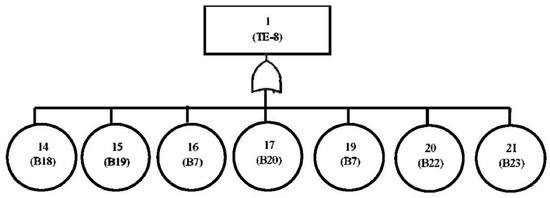
Figure 9.
Simplification of FT-8.
3.5. Risk Analysis by ETA
To evaluate the final value of the CDF, a corresponding event tree (ET) associated with different initiators must be constructed. An ET is developed by the order of safety systems that were functioning at the time the initial event appeared.
In this study, there are 5 postulated initiating events that could occur in the primary RSG-GAS cooling system (Table 7). The development of the event tree (ET) is based on these 5 initial events (ET1 through ET5). The initial event frequency used in the calculations of ET1 through ET5 is taken from the IAEA [38] and presented in Table 8.
Table 7.
Internal initial events of the RSG-GAS primary cooling system [34].
Table 8.
Initiator frequency data of event tree [38].
3.5.1. LOCA 1
LOCA 1 is a loss of coolant due to leakage of the primary cooling pipe after the isolation valve. If there is a leak in the area after the isolation valve, and the pond water level drops below 12.25 m ± 0.05 m, the reactor protection system will shut down the reactor, the primary isolation valve will shut down automatically, and the pump will be extinguished. The next step is to open the natural isolation valve automatically because of the effect of gravity when the primary system flow rate falls below 15%. Then, the cooling stream through the core reverses its direction (to stream upward), and the discharge of decay heat from the core to the pond water occurs through natural convection. The heat retrieval by the primary system will stop. However, the decay heat of the substance continues. For that, the heat recovery function is transferred to the pool cooling system. The probability of each sequence in the ETA diagram was calculated using Equation (18); for example, the probability of sequence 1.2 is shown as follows, and the calculation results for all sequences can be seen in the LOCA 1 event tree in Figure 10.
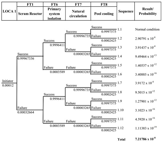
Figure 10.
Event tree of LOCA 1.
3.5.2. LOCA 2
LOCA 2 is a loss of coolant caused by the breaking of the pump casing due to impeller failure. This incident is unlikely, but it must be considered. The breaking of the pump casing due to impeller failure results in a decrease in the mass flow rate of the pump. The mass flow rate signal will turn off the reactor when the mass flow rate of ≤90% ± 5% of the total flow rate of 860 kg/s. The isolation valve closes, and the disposal heat dissipates in a pool cooler by natural circulation. The tree incidence of coolant loss due to the breaking of the pump casing can be seen in Figure 11.
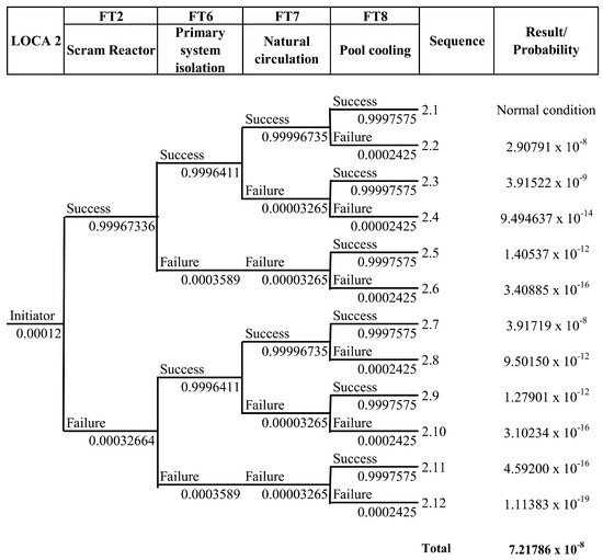
Figure 11.
Event tree of LOCA 2.
3.5.3. LOCA 3
LOCA 3 is a loss of coolant due to the leakage of heat exchangers. In the heat exchanger, the primary water flows over the tube and the secondary water flows over the shell. The assumption of leakage occurs in the tube while the pump is still working. Leakage of these tubes will result in the primary cooling water contaminating the secondary water. At the upper limit of 5 × 10⁻³ Ci/m3, the radiation detection alarm on the secondary circuit will sound and activate the secondary valve to close automatically. Closing this valve means that the secondary cooling system is isolated and its heat cannot be discharged into the environment. As a result, the primary coolant temperature will rise. If the primary outlet temperature is higher than 44 °C, then the reactor protection system will become active, so the reactor will be extinguished and heat dissipation is carried out by the pool cooling system. The result of the calculation of the loss of coolant due to leakage of the heat exchanger can be seen in Figure 12.
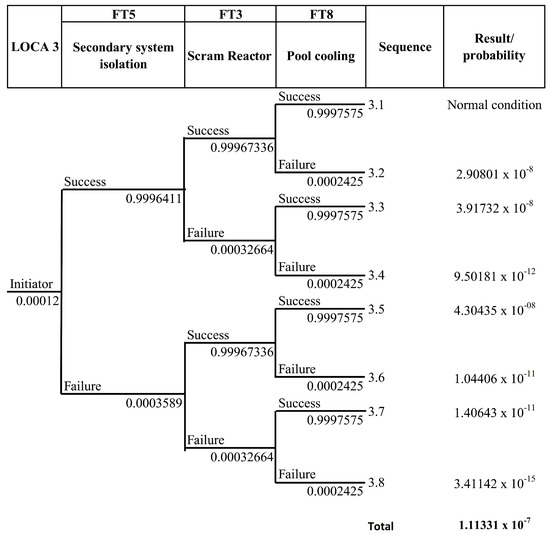
Figure 12.
Event tree of LOCA 3.
3.5.4. LOFA 1
LOFA 1 is a coolant flow loss due to the failure of the primary pump. Sudden primary pump failure is very unlikely because pump performance (flow, flow rate, temperature, and rotational speed) is always monitored during operation. However, it is still possible. The failure of the pump due to the loss of electricity is ignored under these conditions.
In the event of failure of the primary pump, the flywheel from the primary pump works so that the cooling is still running. In conditions of mass flow rate ≤ 90% ± 5% of the total flow rate of 860 kg/s, the reactor will be extinguished. Further heat dissipation will be done naturally by the pool cooling system. The tree incidence of loss of coolant flow due to failure of the primary pump can be seen in Figure 13.
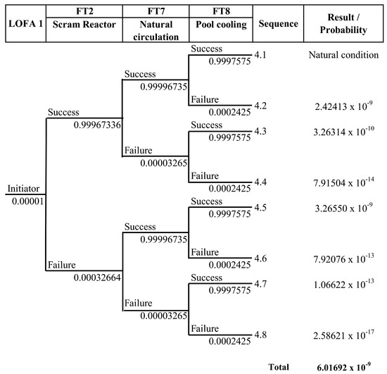
Figure 13.
Event tree of LOFA 1.
3.5.5. LOFA 2
LOFA 2 is a loss of coolant flow due to valve failure. The primary isolation valve serves to maintain the integrity of the reactor pool when a leak occurs. If the primary cooling system leaks, the inlet and outlet valves will close. However, the sudden closing of the valves while the reactor is still operating can cause accidents due to reduced coolant flow in the reactor core. It is assumed that this failure only occurs on valve AA01. The primary isolation valve signal is installed in the reactor protection system, so if this signal is on, at a threshold of 3° of rotation, the reactor will scram. Furthermore, the residual heat will be discharged through a pool cooling system that works naturally in the presence of a natural circulation valve. The event tree of the primary isolation valve failure can be seen in Figure 14.
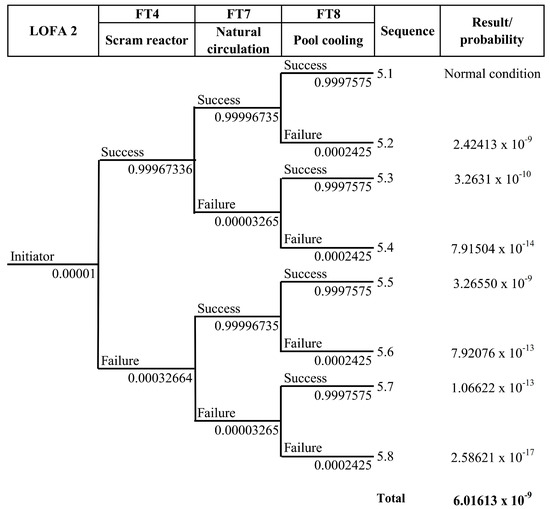
Figure 14.
Event tree of LOFA 2.
3.6. Analysis of Results
The sequence of events 1.1, 2.1, 3.1, 4.1, and 5.1 are shown in Figure 10, Figure 11, Figure 12, Figure 13 and Figure 14 under normal conditions. Under these conditions, if the initial incident of the accident arises, the safety system can work normally by its function, so that no further accidents occur. In other sequences of events, there are safety systems that fail in performing their functions. The maximum probability of event according to the ETA result is 4.304 × 10⁻⁸/year. However, based on the results of the ETA, the risk probability value in the primary cooling system of RSG-GAS is below the CDF value set by the IAEA (10−5/year). Thus, it can be concluded that the reactor is safe to operate.
This can be achieved because the maintenance program of RSG-GAS has run well, the workers have been working following applicable procedures, and they also have personnel certification. This personnel certification is issued by The Nuclear Energy Regulatory Agency of Indonesia (Badan Pengawas Tenaga Nuklir, BAPETEN) in the form of a work permit application to the maintenance staff (supervisor of maintenance and maintenance technician), supervisor of reactor, operator of the reactor, nuclear radiation protection officer, and safeguard officer.
It is important to notice that this proposed approach should be applied in the PSA by FTA when basic events do not have their corresponding historical failure data. Expert judgment is the only mean to collect basic event occurrence likelihoods. On the other hand, when all basic events have their corresponding historical failure data to statistically evaluate their reliability, conventional FTA should be applied.
4. Conclusions
FFTA can be used as an alternative PSA method, especially if component failure data are not available or are insufficient. The risk value of the primary cooling system of RSG-GAS complies with the IAEA-specified CDF limit, i.e., not greater than 10−5/year of reactor operation. The ETA method used to obtain the probability of each event gives a maximum value of 4.304 × 10⁻⁸/year. So, it can be stated that the reactor is safe to operate.
Author Contributions
Conceptualization, H.H.; Methodology, J.H.P.; Validation, H.H., J.H.P. and A.R.K.; Formal Analysis, J.H.P. and A.R.K.; Investigation, J.H.P., A.R.K. and E.; Resources, J.H.P., A.R.K. and E.; Data Curation, J.H.P., A.R.K., and E.; Writing—Original Draft Preparation, A.R.K.; Writing—Review and Editing, J.H.P. and A.R.K.; Visualization, J.H.P. and A.R.K.; Supervision, H.H. and M.Y.; Project Administration, A.R.K.; Funding Acquisition, H.H. All authors have read and agreed to the published version of the manuscript.
Funding
This research was funded by the World Class Professor Program from the Ministry of Research, Technology and Higher Education of The Republic of Indonesia. This research also was funded by the United States Agency for International Development (USAID) through the Sustainable Higher Education Research Alliance (SHERA) Program for Universitas Indonesia’s Scientific Modeling, Application, Research and Training for City-centered Innovation and Technology (SMART CITY) Project, Grant #AID-497-A-1600004, sub-grant #IIE-00000078-UI-1.
Acknowledgments
The authors gratefully acknowledge the research support provided by Universitas Indonesia through Grant for Article Publication in the International Journal Q1Q2 and the Ministry of Research, Technology and Higher Education, the Republic of Indonesia through the World Class Professor Program Scheme—A (number T/41/D2.3/KK.04.05/2019).
Conflicts of Interest
The authors declare no conflict of interest. The funders had no role in the design of the study; in the collection, analyses, or interpretation of data; in the writing of the manuscript; or in the decision to publish the results.
Appendix A
Eight fault trees describe the failure that may occur in the primary cooling system of the RSG-GAS, as follows.
- Reactor scram failure activated by pool water-level signal
 Figure A1. Fault tree of reactor scram failure activated by pool water-level signal. Note: 1 = reactor fail to scram. 2 = control rods insertion fail (B1). 3 = contact 6 system fail (B2). 4 = no signal. 5 = no scram manually. 6 = no scram from automatic system. 7 = the operator does not receive an alarm. 8 = operator fail (B7). 9 = detector system of JAA-01 CL 811 and 821 fail. 10 = detector system of JAA-01 CL 831 and 821 fail. 11 = detector system of JAA-01 CL 811 and 831 fail. 12 = detector system fail. 13 = alarm fail (B3). 14 = detector system of JAA-01 CL 811 fail. 15 = detector system of JAA-01 CL 821 fail. 16 = detector system of JAA-01 CL 831 fail. 17 = detector fail (B4). 18 = transmitter fail (B5). 19 = buffer fail (B6).Figure A1. Fault tree of reactor scram failure activated by pool water-level signal. Note: 1 = reactor fail to scram. 2 = control rods insertion fail (B1). 3 = contact 6 system fail (B2). 4 = no signal. 5 = no scram manually. 6 = no scram from automatic system. 7 = the operator does not receive an alarm. 8 = operator fail (B7). 9 = detector system of JAA-01 CL 811 and 821 fail. 10 = detector system of JAA-01 CL 831 and 821 fail. 11 = detector system of JAA-01 CL 811 and 831 fail. 12 = detector system fail. 13 = alarm fail (B3). 14 = detector system of JAA-01 CL 811 fail. 15 = detector system of JAA-01 CL 821 fail. 16 = detector system of JAA-01 CL 831 fail. 17 = detector fail (B4). 18 = transmitter fail (B5). 19 = buffer fail (B6).
- Reactor scram failure activated by mass flow rate signal
 Figure A2. Fault tree of reactor scram failure activated by mass flow rate signal. Note: 1 = reactor fail to scram. 2 = control rods insertion fail (B1). 3 = contact 6 system fail (B2). 4 = no signal. 5 = no scram manually. 6 = no scram from automatic system. 7 = the operator does not receive an alarm. 8 = operator fail (B7). 9 = detector system of JAA-01 CL 811 and 821 fail. 10 = detector system of JAA-01 CL 831 and 821 fail. 11 = detector system of JAA-01 CL 811 and 831 fail. 12 = detector system fail. 13 = alarm fail (B3). 14 = detector system of JAA-01 CL 811 fail. 15 = detector system of JAA-01 CL 821 fail. 16 = detector system of JAA-01 CL 831 fail. 17 = detector fail (B4). 18 = transmitter fail (B5). 19 = buffer fail (B6).Figure A2. Fault tree of reactor scram failure activated by mass flow rate signal. Note: 1 = reactor fail to scram. 2 = control rods insertion fail (B1). 3 = contact 6 system fail (B2). 4 = no signal. 5 = no scram manually. 6 = no scram from automatic system. 7 = the operator does not receive an alarm. 8 = operator fail (B7). 9 = detector system of JAA-01 CL 811 and 821 fail. 10 = detector system of JAA-01 CL 831 and 821 fail. 11 = detector system of JAA-01 CL 811 and 831 fail. 12 = detector system fail. 13 = alarm fail (B3). 14 = detector system of JAA-01 CL 811 fail. 15 = detector system of JAA-01 CL 821 fail. 16 = detector system of JAA-01 CL 831 fail. 17 = detector fail (B4). 18 = transmitter fail (B5). 19 = buffer fail (B6).
- Reactor scram failure activated by outlet temperature signal of primary heat exchanger
 Figure A3. Fault tree of reactor scram failure activated by the outlet temperature signal of the primary heat exchanger. Note: 1 = reactor fail to scram. 2 = control rods insertion fail (B1). 3 = contact 6 system fail (B2). 4 = no signal. 5 = no scram manually. 6 = no scram from automatic system. 7 = the operator does not receive an alarm. 8 = operator fail (B7). 9 = detector system of JAA-01 CL 811 and 821 fail. 10 = detector system of JAA-01 CL 831 and 821 fail. 11 = detector system of JAA-01 CL 811 and 831 fail. 12 = detector system fail. 13 = alarm fail (B3). 14 = detector system of JAA-01 CL 811 fail. 15 = detector system of JAA-01 CL 821 fail. 16 = detector system of JAA-01 CL 831 fail. 17 = detector fail (B4). 18 = transmitter fail (B5). 19 = buffer fail (B6).Figure A3. Fault tree of reactor scram failure activated by the outlet temperature signal of the primary heat exchanger. Note: 1 = reactor fail to scram. 2 = control rods insertion fail (B1). 3 = contact 6 system fail (B2). 4 = no signal. 5 = no scram manually. 6 = no scram from automatic system. 7 = the operator does not receive an alarm. 8 = operator fail (B7). 9 = detector system of JAA-01 CL 811 and 821 fail. 10 = detector system of JAA-01 CL 831 and 821 fail. 11 = detector system of JAA-01 CL 811 and 831 fail. 12 = detector system fail. 13 = alarm fail (B3). 14 = detector system of JAA-01 CL 811 fail. 15 = detector system of JAA-01 CL 821 fail. 16 = detector system of JAA-01 CL 831 fail. 17 = detector fail (B4). 18 = transmitter fail (B5). 19 = buffer fail (B6).
- Reactor scram failure activated by position signal of primary isolation valve
 Figure A4. Fault tree of reactor scram failure activated by the position signal of the primary isolation valve. Note: 1 = reactor fail to scram. 2 = control rods insertion fail (B1). 3 = contact 6 system fail (B2). 4 = no signal. 5 = no scram manually. 6 = no scram from automatic system. 7 = the operator does not receive an alarm. 8 = operator fail (B7). 9 = detector system of JAA-01 CL 811 and 821 fail. 10 = detector system of JAA-01 CL 831 and 821 fail. 11 = detector system of JAA-01 CL 811 and 831 fail. 12 = detector system fail. 13 = alarm fail (B3). 14 = detector system of JAA-01 CL 811 fail. 15 = detector system of JAA-01 CL 821 fail. 16 = detector system of JAA-01 CL 831 fail. 17 = detector fail (B4). 18 = transmitter fail (B5). 19 = buffer fail (B6).Figure A4. Fault tree of reactor scram failure activated by the position signal of the primary isolation valve. Note: 1 = reactor fail to scram. 2 = control rods insertion fail (B1). 3 = contact 6 system fail (B2). 4 = no signal. 5 = no scram manually. 6 = no scram from automatic system. 7 = the operator does not receive an alarm. 8 = operator fail (B7). 9 = detector system of JAA-01 CL 811 and 821 fail. 10 = detector system of JAA-01 CL 831 and 821 fail. 11 = detector system of JAA-01 CL 811 and 831 fail. 12 = detector system fail. 13 = alarm fail (B3). 14 = detector system of JAA-01 CL 811 fail. 15 = detector system of JAA-01 CL 821 fail. 16 = detector system of JAA-01 CL 831 fail. 17 = detector fail (B4). 18 = transmitter fail (B5). 19 = buffer fail (B6).
- Secondary system isolation failure
 Figure A5. Fault tree of secondary system isolation failure. Note: 1 = secondary system isolation Figure. 2 = valve fails to closed automatically. 3 = valve fails to closed manually. 4 = isolation valve fail. 5 = detector system fail. 6 = signal fail (B8). 7 = display fail (B9). 8 = operator fails to operate the valve (B7). 9 = valve PA-01-AA-14 fail/stuck (B14). 10 = valve PA-01-AA-16 fail/ stuck (B15). 11 = detector fail (B4). 12 = transmitter fail (B5). 13 = buffer fail (B6).Figure A5. Fault tree of secondary system isolation failure. Note: 1 = secondary system isolation Figure. 2 = valve fails to closed automatically. 3 = valve fails to closed manually. 4 = isolation valve fail. 5 = detector system fail. 6 = signal fail (B8). 7 = display fail (B9). 8 = operator fails to operate the valve (B7). 9 = valve PA-01-AA-14 fail/stuck (B14). 10 = valve PA-01-AA-16 fail/ stuck (B15). 11 = detector fail (B4). 12 = transmitter fail (B5). 13 = buffer fail (B6).
- Primary system isolation failure
 Figure A6. Fault tree of primary system isolation failure. Note: 1 = primary system isolation fail. 2 = valve fails to close automatically. 3 = valve fails to close manually. 4 = in line isolation valve fail. 5 = out line isolation valve fail. 6 = detector system fail. 7 = signal fail (B8). 8 = display fail (B9). 9 = operator fail to operate the valve (B7). 10 = valve of JE-01-AA-01 fail (B10). 11 = valve of JE-01-AA-02 fail (B11). 12 = valve of JE-01-AA-18 fail (B12). 13 = valve of JE-01-AA-19 fail (B13). 14 = detector system of JAA-01 CL 811 and 821 fail. 15 = detector system of JAA-01 CL 831 and 821 fail. 16 = detector system of JAA-01 CL 811 and 831 fail. 17 = detector system of JAA-01 CL 811 fail. 18 = detector system of JAA-01 CL 821 fail. 19 = detector system of JAA-01 CL 831 fail. 20 = detector fail (B4). 21 = transmitter fail (B5). 22 = buffer fail (B6).Figure A6. Fault tree of primary system isolation failure. Note: 1 = primary system isolation fail. 2 = valve fails to close automatically. 3 = valve fails to close manually. 4 = in line isolation valve fail. 5 = out line isolation valve fail. 6 = detector system fail. 7 = signal fail (B8). 8 = display fail (B9). 9 = operator fail to operate the valve (B7). 10 = valve of JE-01-AA-01 fail (B10). 11 = valve of JE-01-AA-02 fail (B11). 12 = valve of JE-01-AA-18 fail (B12). 13 = valve of JE-01-AA-19 fail (B13). 14 = detector system of JAA-01 CL 811 and 821 fail. 15 = detector system of JAA-01 CL 831 and 821 fail. 16 = detector system of JAA-01 CL 811 and 831 fail. 17 = detector system of JAA-01 CL 811 fail. 18 = detector system of JAA-01 CL 821 fail. 19 = detector system of JAA-01 CL 831 fail. 20 = detector fail (B4). 21 = transmitter fail (B5). 22 = buffer fail (B6).
- Primary cooler natural circulation failure
 Figure A7. Fault tree of primary cooler natural circulation failure. Note: 1 = natural circulation of primary cooler fail. 2 = circulation flap fails to open/stuck (B16). 3 = pressure difference error (B17).Figure A7. Fault tree of primary cooler natural circulation failure. Note: 1 = natural circulation of primary cooler fail. 2 = circulation flap fails to open/stuck (B16). 3 = pressure difference error (B17).
- Pool cooling failure
 Figure A8. Fault tree of pool cooling failure. Note: 1 = pool cooling fail. 2 = JNA 10 fail. 3 = JNA 20 fail. 4 = JNA 30 fail. 5 = pump JNA 10 AP-01 fail. 6 = blower JNA 10 BC-02 fail. 7 = heat exchanger JNA 10 BC-01 fail. 8 = pump JNA 20 AP-01 fail. 9 = blower JNA 20 BC-02 fail. 10 = heat exchanger JNA 20 BC-01 fail. 11 = pump JNA 30 AP-01 fail. 12 = blower JNA 30 BC-02 fail. 13 = heat exchanger JNA 30 BC-01 fail. 14 = pump fails to start (B18). 15 = pump fails to operate after start (B19). 16 = operator fail to operate pump (B7). 17 = blower fail start (B20). 18 = blower fail after start (B21). 19 = operator fail to operate blower (B7). 20 = heat exchanger clogged (B22). 21 = heat exchanger leaked (B23).Figure A8. Fault tree of pool cooling failure. Note: 1 = pool cooling fail. 2 = JNA 10 fail. 3 = JNA 20 fail. 4 = JNA 30 fail. 5 = pump JNA 10 AP-01 fail. 6 = blower JNA 10 BC-02 fail. 7 = heat exchanger JNA 10 BC-01 fail. 8 = pump JNA 20 AP-01 fail. 9 = blower JNA 20 BC-02 fail. 10 = heat exchanger JNA 20 BC-01 fail. 11 = pump JNA 30 AP-01 fail. 12 = blower JNA 30 BC-02 fail. 13 = heat exchanger JNA 30 BC-01 fail. 14 = pump fails to start (B18). 15 = pump fails to operate after start (B19). 16 = operator fail to operate pump (B7). 17 = blower fail start (B20). 18 = blower fail after start (B21). 19 = operator fail to operate blower (B7). 20 = heat exchanger clogged (B22). 21 = heat exchanger leaked (B23).
References
- Han, Z.Y.; Weng, W.G. Comparison study on qualitative and quantitative risk assessment methods for urban natural gas pipeline network. J. Hazard. Mater. 2011, 189, 509–518. [Google Scholar] [CrossRef]
- Barghi, B. Qualitative and quantitative project risk assessment using a hybrid PMBOK model developed under uncertainty conditions. Heliyon 2020, 6, e03097. [Google Scholar] [CrossRef] [PubMed]
- Chan, H.K.; Wang, X. Fuzzy hierarchical model for risk assessment. Lond. Springer 2013, 10, 971–978. [Google Scholar]
- Hermansyah, H.; Nur Hidayat, M.; Kumaraningrum, A.; Yohda, M.; Shariff, A. Assessment, Mitigation, and Control of Potential Gas Leakage in Existing Building Not Designed for Gas Installation in Indonesia. Energies 2018, 11, 2970. [Google Scholar] [CrossRef]
- Nie, R.X.; Tian, Z.P.; Wang, X.K.; Wang, J.Q.; Wang, T.L. Risk evaluation by FMEA of supercritical water gasification system using multi-granular linguistic distribution assessment. Knowl. Based Syst. 2018, 162, 185–201. [Google Scholar] [CrossRef]
- De Gusmão, A.P.H.; Silvia, M.M.; Poleto, T.; e Silvia, L.C.; Costa, A.P.C.S. Cybersecurity risk analysis model using fault tree analysis and fuzzy decision theory. Int. J. Inf. Manag. 2018, 43, 248–260. [Google Scholar] [CrossRef]
- Chen, G.; Wang, X.; Wang, R.; Liu, G. Health risk assessment of potentially harmfull elements in subsidence water bodies using a Monte Carlo approach: An example from the Huainan coal mining area, China. Ecotoxicol. Environ. Saf. 2019, 171, 737–745. [Google Scholar] [CrossRef]
- Vesely, W.E.; Goldberg, F.F.; Roberts, N.H.; Haasl, D.F. Fault Tree Handbook; No. NUREG-0492; Nuclear Regulatory Commission: Washington, DC, USA, 1981.
- Rajakarunakaran, S.; Kumar, A.M.; Prabhu, V.A. Applications of fuzzy faulty tree analysis and expert elicitation for evaluation of risks in LPG refueling station. J. Loss Prev. Process Ind. 2015, 33, 109–123. [Google Scholar] [CrossRef]
- Aneziris, O.; Housiadas, C.; Stakakis, M.; Papazoglou, I. Probabilistic safety analysis of a Greek Research Reactor. Ann. Nucl. Energy 2004, 31, 481–516. [Google Scholar] [CrossRef]
- Barati, R.; Setayeshi, S. Probabilistic Safety Assessment of Tehran research reactor based on a synergy between plant topology and hierarchical evolutions. Prog. Nucl. Energy 2014, 70, 199–208. [Google Scholar] [CrossRef]
- Purba, J.H.; Tjahyani, D.S.; Ekariansyah, A.S.; Tjahjono, H. Fuzzy probability based fault tree analysis to propagate and quantify epistemic uncertainty. Ann. Nucl. Energy 2015, 85, 1189–1199. [Google Scholar] [CrossRef]
- Guimarães, A.C.F.; Lapa, C.M.F. Parametric fuzzy study for effects analysis of age on PWR containment cooling system. Appl. Soft Comput. 2008, 8, 1562–1571. [Google Scholar] [CrossRef]
- Bainbridge, W.S. Leadership in Science and Technology: A Reference Handbook; Sage Publications: Southend Oaks, CA, USA, 2011. [Google Scholar]
- Bector, C.; Chandra, S. Fuzzy numbers and fuzzy arithmetic. In Fuzzy Mathematical Programming and Fuzzy Matrix Games; Springer: Berlin, Germany, 2005; pp. 39–56. [Google Scholar]
- Onisawa, T. Fuzzy theory in reliability analysis. Fuzzy Sets Syst. 1989, 30, 361–363. [Google Scholar] [CrossRef]
- Misra, K.B.; Weber, G.G. Use of fuzzy set theory for level-I studies in probabilistic risk assessment. Fuzzy Sets Syst. 1990, 37, 139–160. [Google Scholar] [CrossRef]
- Onisawa, T. An application of fuzzy concepts to modelling of reliability analysis. Fuzzy Sets Syst. 1990, 37, 267–286. [Google Scholar] [CrossRef]
- Suresh, P.; Babar, A.; Raj, V.V. Uncertainty in fault tree analysis: A fuzzy approach. Fuzzy Sets Syst. 1996, 83, 135–141. [Google Scholar] [CrossRef]
- Yuhua, D.; Datao, Y. Estimation of failure probability of oil and gas transmission pipelines by fuzzy fault tree analysis. J. Loss Prev. Process Ind. 2005, 18, 83–88. [Google Scholar] [CrossRef]
- Tyagi, S.K.; Pandey, D.; Kumar, V. Fuzzy fault tree analysis for fault diagnosis of cannula fault in power transformer. Appl. Math. 2011, 2, 1346–1355. [Google Scholar] [CrossRef]
- Komal. Fuzzy fault tree analysis for patient safety risk modeling in healthcare under uncertainty. Appl. Soft Comput. 2015, 37, 942–951. [Google Scholar] [CrossRef]
- Cheliyan, A.; Bhattacharyya, S. Fuzzy fault tree analysis of oil and gas leakage in subsea production systems. J. Ocean Eng. Sci. 2017, 3, 38–48. [Google Scholar] [CrossRef]
- Purba, J.H. A fuzzy-based reliability approach to evaluate basic events of fault tree analysis for nuclear power plant probabilistic safety assessment. Ann. Nucl. Energy 2014, 70, 21–29. [Google Scholar] [CrossRef]
- Guimarães, A.C.; Ebecken, N.F. FuzzyFTA: A fuzzy fault tree system for uncertainty analysis. Ann. Nucl. Energy 1999, 26, 523–532. [Google Scholar] [CrossRef]
- Guimarães, A.C.F.; Lapa, C.M.F.; Simões Filho, F.F.L.; Cabral, D.C. Fuzzy uncertainty modeling applied to AP1000 nuclear power plant LOCA. Ann. Nucl. Energy 2011, 38, 1775–1786. [Google Scholar] [CrossRef]
- Purba, J.H. Fuzzy probability on reliability study of nuclear power plant probabilistic safety assessment: A review. Prog. Nucl. Energy 2014, 76, 73–80. [Google Scholar] [CrossRef]
- Purba, J.H.; Lu, J.; Zhang, G.; Pedrycz, W. A fuzzy reliability assessment of basic events of fault trees through qualitative data processing. Fuzzy Sets Syst. 2013, 243, 50–69. [Google Scholar] [CrossRef]
- IAEA. Application of Probabilistic Safety Assessment for Nuclear Power Plants; IAEA-TECDOC-1200; IAEA: Vienna, Austria, 2001. [Google Scholar]
- IAEA. Probabilistic Safety Assessment for Research Reactor; IAEA-TECDOC-400; IAEA: Vienna, Austria, 1986. [Google Scholar]
- PRSG. Laporan Analisis Keselamatan (LAK) RSG-GAS Rev 11; PRSG: Jakarta, Indonesia, 2017. [Google Scholar]
- Subekti, M.; Sunaryo, G.R. Reliability Analysis of RSG-GAS Primary Cooling System to Support Aging Management Program. J. Phys. Conf. Ser. 2018, 962, 012002. [Google Scholar]
- Tyas, R.L. Evaluasi Risiko Sistem Pendingin Primer Reaktor G.A. Siwabessy sebagai Bagian Dari Analisis Keselamatan untuk Mencegah dan Meminimasi Dampak Kecelakaan. Master’s Thesis, Universitas Indonesia, Depok, Indonesia, 2015. [Google Scholar]
- Kumaraningrum, A.R.; Hermansyah, H.; Purba, J.H. Experts’ selection in the application of fuzzy fault tree analysis to Evaluate an RSG–GAS primary cooling system. In Proceedings of the 8th Annual Basic Science International Conference: Coverage of Basic Sciences toward the World’s Sustainability Challenges, Malang, Indonesia, 6–7 March 2018; p. 020001. [Google Scholar] [CrossRef]
- Onisawa, T. An approach to human reliability in man-machine systems using error possibility. Fuzzy Sets Syst. 1988, 27, 87–103. [Google Scholar] [CrossRef]
- Purba, J.H. Framework, Approach and System of Intelligent Fault Tree Analysis for Nuclear Safety Assessment. Ph.D. Thesis, University of Technology Sydney, Sydney, Australia, 2013. [Google Scholar]
- Dhillon, B.S. Design Reliability: Fundamentals and Applications; CRC Press: Boca Raton, FL, USA, 1999. [Google Scholar]
- IAEA. Component Reliability Data for Use in Probabilistic Safety Assessment IAEA-TECDOC-478; IAEA: Vienna, Austria, 1989. [Google Scholar]


© 2020 by the authors. Licensee MDPI, Basel, Switzerland. This article is an open access article distributed under the terms and conditions of the Creative Commons Attribution (CC BY) license (http://creativecommons.org/licenses/by/4.0/).