Article

A Novel Technique for Load Frequency Control of Multi-Area Power Systems

by
Ali Dokht Shakibjoo
1,
Mohammad Moradzadeh
1,2,*,
Seyed Zeinolabedin Moussavi
1 and
Lieven Vandevelde
2
1
Electrical Engineering Department, Shahid Rajaee Teacher Training University, Tehran 1678815811, Iran
2
Department of Electromechanical, Systems and Metal Engineering, Ghent University, 9052 Ghent, Belgium
*
Author to whom correspondence should be addressed.
Energies 2020, 13(9), 2125; https://doi.org/10.3390/en13092125
Submission received: 12 March 2020 / Revised: 19 April 2020 / Accepted: 20 April 2020 / Published: 25 April 2020

Abstract

:
In this paper, an adaptive type-2 fuzzy controller is proposed to control the load frequency of a two-area power system based on descending gradient training and error back-propagation. The dynamics of the system are completely uncertain. The multilayer perceptron (MLP) artificial neural network structure is used to extract Jacobian and estimate the system model, and then, the estimated model is applied to the controller, online. A proportional–derivative (PD) controller is added to the type-2 fuzzy controller, which increases the stability and robustness of the system against disturbances. The adaptation, being real-time and independency of the system parameters are new features of the proposed controller. Carrying out simulations on New England 39-bus power system, the performance of the proposed controller is compared with the conventional PI, PID and internal model control based on PID (IMC-PID) controllers. Simulation results indicate that our proposed controller method outperforms the conventional controllers in terms of transient response and stability.

1. Introduction

Increasing demand for electrical power, complexity and nonlinearity of electrical power systems as well as the need for supply of electricity with high stability and reliability emphasize the importance of the load frequency control (LFC) in power systems. Furthermore, controlling the system in emergency situations and sudden load changes such as short-term interruption is necessary to prevent frequency deviations. Conventional controllers such as PI and PID are designed to best operate under specific operating conditions, while their control performance is reduced if operating conditions vary under sudden load changes; adjusting parameters of conventional controllers might be improper for the new operating points. Therefore, for controlling frequency and dynamic performance of a generator in a wide range of operating conditions, adaptive controllers are suitable. The use of a fuzzy controller to regulate the voltage and frequency of the generator has become more popular during recent years [1,2,3,4,5]. Firstly, they are independent of the system model and do not allow the complexities of the dynamic system model to be included in the design process. Secondly, the fuzzy controllers operation depends on the human experts which have made this type of controller very popular in the industry [6,7,8,9,10]. Since the power system has uncertain nonlinear dynamics, the controllers with constant gain do not perform well under variable and uncertain loading conditions. Therefore, some methods such as artificial neural network, fuzzy logic and fuzzy neural networks have been used for frequency control [11,12], but these controllers are vulnerable to uncertainties and noises and do not perform well against changing parameters.
In this paper, however, we propose a type-2 neural fuzzy controller, which can model more uncertainty than type-1 fuzzy controllers and has lower sensitivity to the system parameters by ignoring the system dynamics. In addition, it reduces computation by type-reduction, and it can adapt to new requirements of system.
In the last decade, various methods have been developed to incorporate adaptive fuzzy logic into the frequency control [13,14,15,16]. Some approach is suggested to improve the performance of fuzzy PI and PID controllers in [17,18,19,20,21]. Moreover, an improved automatic generation control (AGC) method named predictive optimal 2-degree-of-freedom proportion integral differential (PO-2-DOF-PID) is proposed in [22]. In [23], the fuzzy logic is suggested to control the frequency deviation of a multi-area power system, in which physical constraints such as the rate of production and the nonlinear characteristic of the governor dead-band were considered.
Online fuzzy PI controller tuning using the bat algorithm method is presented in [24]. In addition, an artificial neural network is used to control power generation in a multi-area thermal power plant system in [25] and a third-order observer-based sliding mode control in [26]. An adaptive neural fuzzy control system was applied to improve LFC in both hydro and thermal power systems in [27]. In [28], a novel PID-like neural network controller is proposed. The resilient back-propagation algorithm with sign instead of the gradient is used to derive the rule of updating network weights. The simulation experiment was carried out on an inverted-pendulum system. Reference [29] presents an adaptive PID-like controller using a modified neural network for learning of system dynamics. This controller applied to speed control of DC machine. Moreover, a simplified adaptive neuro-fuzzy inference system (ANFIS) structure acting as a PID-like feedback controller to control nonlinear systems is presented in [30]. In fact, all of the above-mentioned studies focused on system dynamics. However, in our proposed method in this paper, the controller is not dependent on the system dynamic parameters, and system parameters are assumed to be uncertain, and the controller is designed online. The proposed controller is adaptive and adapts itself to system new conditions. It can be applied in practical and real-world applications including the standard 39-bus New England system that has satisfied our expectations despite nonlinearity of the power system. Furthermore, the proposed controller is based on type-2 neural fuzzy, which performs better than type-1 fuzzy and models more uncertainties. The control parameters were trained by the descending gradient method and the error back-propagation posture so that the area control error signal could be zero. Jacobian of the system model is extracted and is applied to the controller. Then, the control error signal is applied as a PID to the controller input in order to increase the speed and compensate for the slower speed due to parameter training. Then, the suggested method is compared with the PI, IMC-PID and PID controllers for evaluation and comparison. Finally, to show effectiveness of proposed control, we applied this method on New England test system 39-bus, which is widely used as a standard system for testing of the power system analysis and control. Compared to our previous work in [31], the distinct features of this paper are as follows:
  • An adaptive type-2 fuzzy control system is proposed for frequency control of the two-area power system.
  • PD controller is added to the controller to increase stability and robustness.
  • Two re-heating and non re-heating areas are considered.
  • Plant dynamics are assumed to be uncertain.
  • Unlike similar methods, the Jacobian of the plant is not required.
  • The center-of-set (COS) is used to order-reduction.
  • The controller performance is evaluated on a larger-scale power system.
The remainder of this paper is organized as follows: Section 2 describes the theory of the proposed controller. Section 3 and Section 4 present the model of the studied system and the simulation results, respectively. Finally, the paper is concluded in Section 5.

2. Theory of the Proposed Structure

2.1. Structure of the MLP Neural Network

The neural network, with its structure shown in Figure 1, is used to model the system for adaptive calculation of the system Jacobian.
The description of the used notation in Figure 1 is as follows:
u ( t z 1 ) , u ( t z 2 ) , , u ( t z n ) : inputs of the neural network;
z 1 , , z n : constant delays;
w 11 1 , w 12 2 , , w 1 n 1 : weights connected to first neuron in the middle layer;
w 21 1 , w 22 1 , , w 2 n 1 : weights connected to second neuron in the middle layer;
w h 1 1 , w h 2 1 , , w h n 1 : weights connected to neuron h, h being the number of neurons in the middle layer;
w 21 , w 22 , , w 2 h : weights connected to output and neurons of the output layer.
Output of neurons of the middle layer are obtained as follows:
n e t i = w i 1 U
o i = g ( n e t i ) , i = 1 , , h
where
U = [ u ( t z 1 ) , u ( t z 2 ) , , u ( t z n ) ] T
w i 1 = [ w i 1 1 , w i 2 1 , , w i n 1 ]
g ( n e t i ) = 1 exp ( n e t i ) 1 + exp ( n e t i )
Inputs of the MLP includes the control signal and output of the system, and the output of the MLP is obtained as follows:
y = w 2 o
where
o = [ o 1 , o 2 , , o h ] T
w = [ w 21 , w 22 , , w 2 h ]
Weights of this neural network are trained such that the cost function E is minimized:
E = 1 2 e e s t 2 = 1 2 ( y d y ) 2
where y d is the desired output, and y is output of the neural network. Weights at t + 1 are w ( t + 1 ) = w ( t ) η E w . Gradient descent and back-propagation error are used for training. In order to obtain E w , the chain differentiation of E w = E e e y y w applies. By substituting E e = e , e y = 1 , y w = 0 , the rule of training weights is obtained as follows:
w 2 ( t + 1 ) = w 2 ( t ) + η e e s t o
Adaptive law for weights of the first layer would be:
w i 1 ( t + 1 ) = w i 1 ( t ) + η e e s t g ´ ( n e t i ) w 2 i U
where w i 1 is the vector of weights connected to i t h neuron in the middle layer, w 2 i the weight connected to output and i t h the neuron in the middle layer. g ´ ( n e t i ) is the derivative of g ( n e t i ) with respect to n e t i which is constant adaptive rate and η is the training rate of gradient descent.
Equation (10) is an adaptive equation based on gradient descent and differentiation with respect to weights of hidden layers.

2.2. System Jacobian

Finally, the obtained model is used to calculate the system Jacobian:
Δ f u c = [ w 11 1 , w 21 1 , , w h 1 1 ] d i a g [ g ´ ( n e t 1 ) , , g ´ ( n e t h ) ] w 2
where
Δ f u c : the derivative of the output with respect to control input;
[ w 11 1 , w 21 1 , , w h 1 1 ] : vector of weights connected to the first input and neurons of the middle layer;
[ g ´ ( n e t 1 ) , , g ´ ( n e t h ) ] : vector of derivative of output of neurons of the middle layer with respect to their input;
w 2 : vector of weights connected to output and neurons of the middle layer.

2.3. Type 2 Fuzzy-Neural Controller Structure

Since the power system has nonlinearity and parametric uncertainties, the control algorithm must be able to operate under uncertain conditions efficiently. Fuzzy neural networks (FNNs) can be considered as an appropriate control structure for such systems both in terms of fuzzy advantage for reducing uncertainties and neural for learning. In general, there are two types of fuzzy; the type-2 fuzzy is the improved type-1 fuzzy, and both have the same fuzzy rules and membership functions. The membership function of the type-1 is a fixed number, while it is a fuzzy set in the type-2. The type-2 fuzzy set has a third dimension, which helps to model the uncertainties where type-1 fuzzy is incapable of modeling uncertainties. The type-2 fuzzy is used when the system complexity is high and high-speed process is needed [32,33]. In the continuous state, a type-2 fuzzy set is defined as follows:
A ˜ = ( x ( x , u ) , μ A ˜ ( x , u ) | x X , u J x [ 0 , 1 ]
where 0 μ A ˜ ( x , u ) 1 . Another expression for A ˜ is:
A ˜ = x X u J x μ A ˜ ( x , u ) ( x , u )
where denotes the union over all admissible input variables x and u. In fact, J x [ 0 , 1 ] represents the primary membership of x, and μ A ˜ ( x , u ) is a type-1 fuzzy set known as the secondary set. An interval type fuzzy is used to reduce the computation in which μ A ˜ ( x , u ) = 1 .
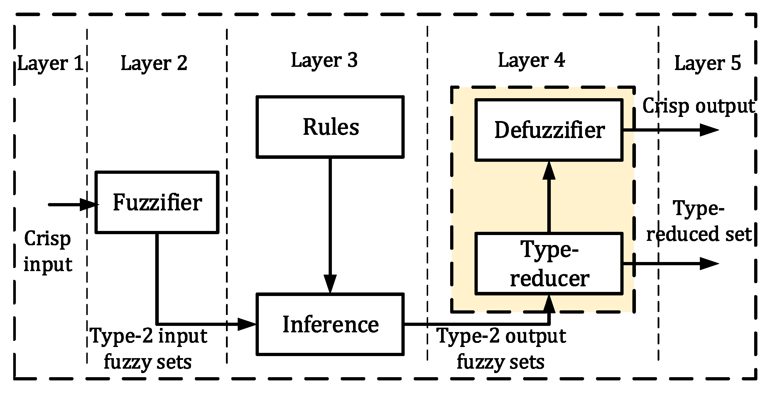
The general structure of a type-2 fuzzy system with 5 layers is shown in Figure 2. A type-2 fuzzy system consists of five main blocks, which are the input fuzzifier, fuzzy rules base, inference engine, defuzzifier and the type reducer. The first layer is the input layer, which is a crisp value. In the second layer “the fuzzifier” process converts a crisp input vector into type-1 or type-2 input fuzzy system. In the inference engine in the third layer, the fuzzy rules “IF–THEN” are combined for representing the rule base. The rule base is extracted from numerical analysis or provided by an expert person. As shown in Figure 2, the output processing block includes two parts: type reducer and defuzzification. Since the inference engine gives type-2 fuzzy system set as output, a new block called “type-reducer” is used between inference engine and defuzzifier that converts fuzzy set into crisp value. The type-2 reducer is an important part which maps the fired rule consequent sets into type-1 fuzzy system to reduce the computation and increase the output speed. There are different methods to convert such as Centroid, Height and Center-Of-Sets (COS). In this paper we used COS type-reduction [34]:
y l = n = 1 L f ¯ n y ̲ n n = 1 L f ¯ n + n = L + 1 N f ̲ n + n = L + 1 N f ¯ n y ̲ n n = 1 L f ¯ n + n = L + 1 N f ̲ n
y r = n = 1 R f ̲ n y ¯ n n = 1 R f ̲ n + n = R + 1 N f ¯ n + n = R + 1 N f ̲ n y ¯ n n = 1 R f ̲ n + n = R + 1 N f ¯ n
It has been demonstrated in [34] that the defuzzified output can be calculated as Equation (15) by simply taking an average of the y l and y r points. y l and y r , as the left and right end points of the type reduced set, are defined in Equation (14), where r and l are the switching points defined between [ 1 , N 1 ] that can be found via the Karnik and Mendel algorithm. f ¯ n , f ̲ n are the firing level, and y ¯ n , y ̲ n are centers of the consequent output, and N is the number of rules.
The numerical output of type-2 fuzzy system is as follows:
y = y l + y r 2
Gaussian membership functions as follows:
μ ¯ A ˜ ( x , u ) = exp ( | | X C k | | 2 σ ¯ k 2 )
μ ̲ A ˜ ( x , u ) = exp ( | | X C k | | 2 σ ̲ k 2 )
k = 1 , , M
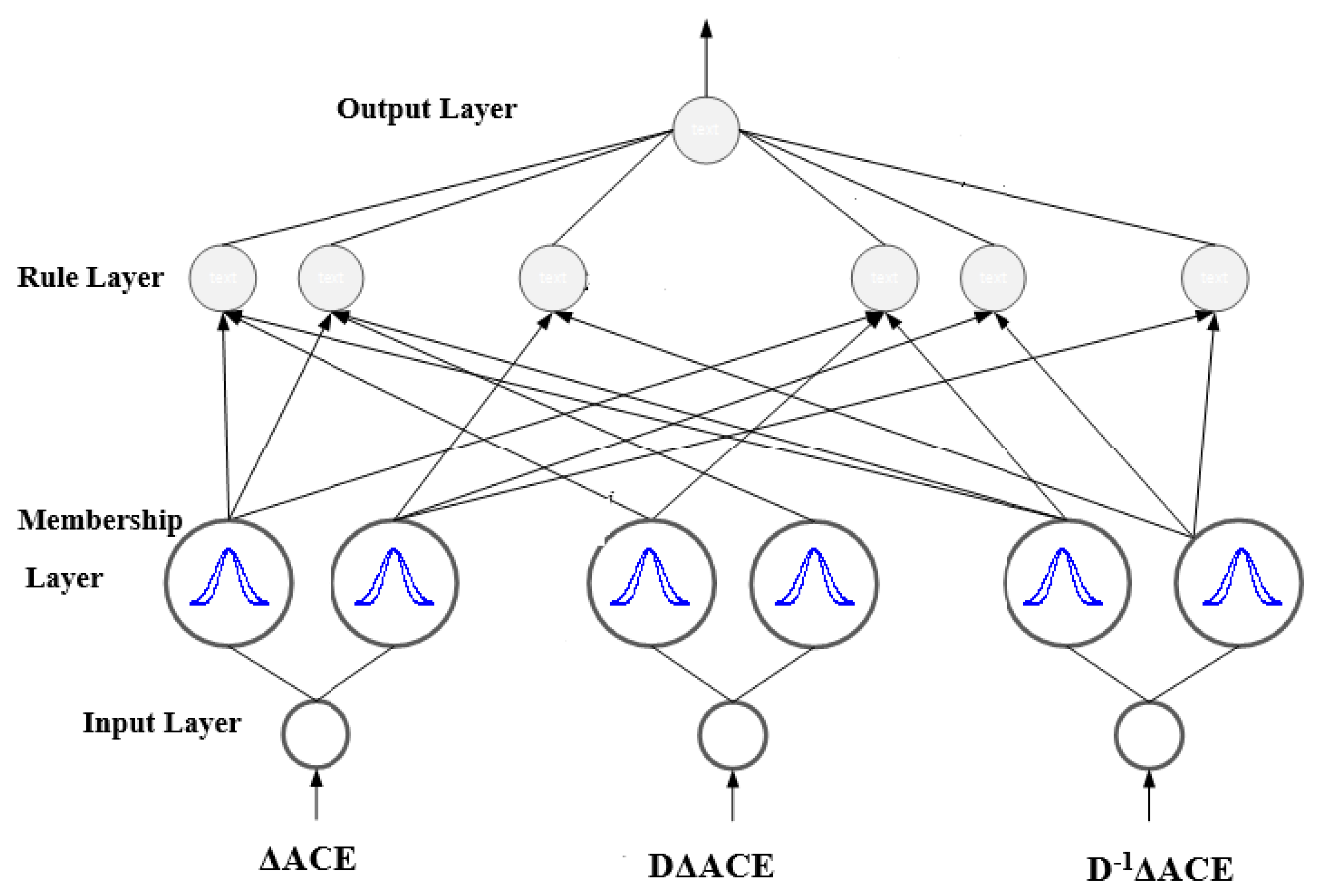
where C i and σ i are considered as the center and width of the Gaussian functions, respectively. The structure of the proposed type-2 fuzzy controller for the multi-area power system is shown in Figure 3. This controller has three inputs ( Δ A C E , D Δ A C E , D 1 A C E ) , where Δ A C E = β Δ f + Δ P t i e , and one output y. The number of utilized rules is 11, which is fixed and is obtained via trial and error.

2.4. Learning by Descending Gradient and Error Back-Propagation

In this section, the proposed controller based on a neural network is introduced. The output of the neuro-fuzzy network constitutes the control signal, and parameters of this neuro-fuzzy network are trained in such way that frequency changes Δ f tend to zero. When Δ f tends to zero, the control objective is satisfied. In the next subsection, the structure of the neuro-fuzzy network and adjustment of its weights are described.
The network weights are trained based on the back-propagation process and the descending gradient training method. The square error between the optimal response (zero velocity changes) and the network output at instant t is considered as the cost function:
E = 1 2 e 2 = 1 2 ( Δ f ) 2
where Δ f the indicates the system output.
The error back-propagation algorithm is used to train the fuzzy system as follows:
w ( t + 1 ) = w ( t ) η E w
where E w is a cost function with respect to neural network parameters and is obtained from Equation (20), where w represents the vector of the weights of the consequent, and η is the descending gradient training rate.
E w = E Δ f Δ f u c u c y y w
In Equation (20), u c indicates the control signal, and y is the output of the neural network.
Δ f u c in Equation (20) is the system Jacobian derived from the system model in Equation (11) and the other terms are computed as follows:
E = 1 2 e 2 = 1 2 ( Δ f ) 2 E Δ f = Δ f
u c = y u c y = 1
y = w T ξ y w = ξ
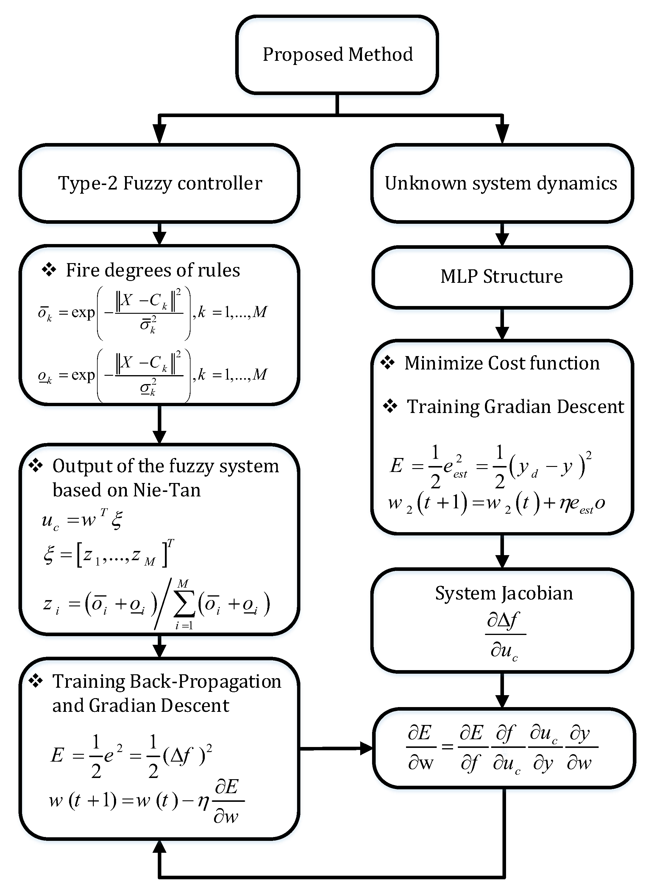
The flowchart of our proposed method is illustrated in Figure 4.

3. Dynamic Model of Power System

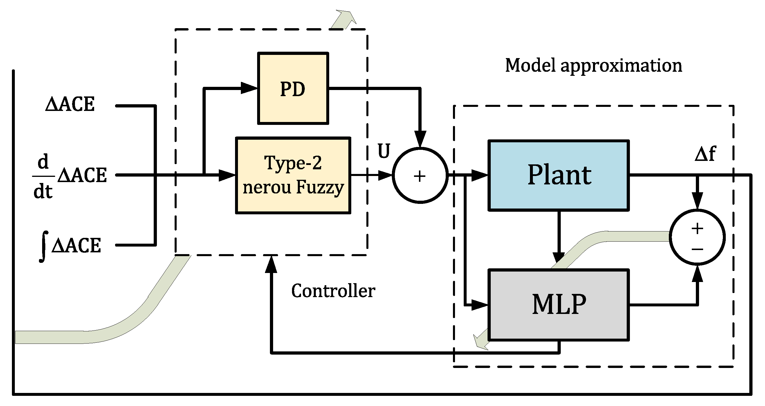
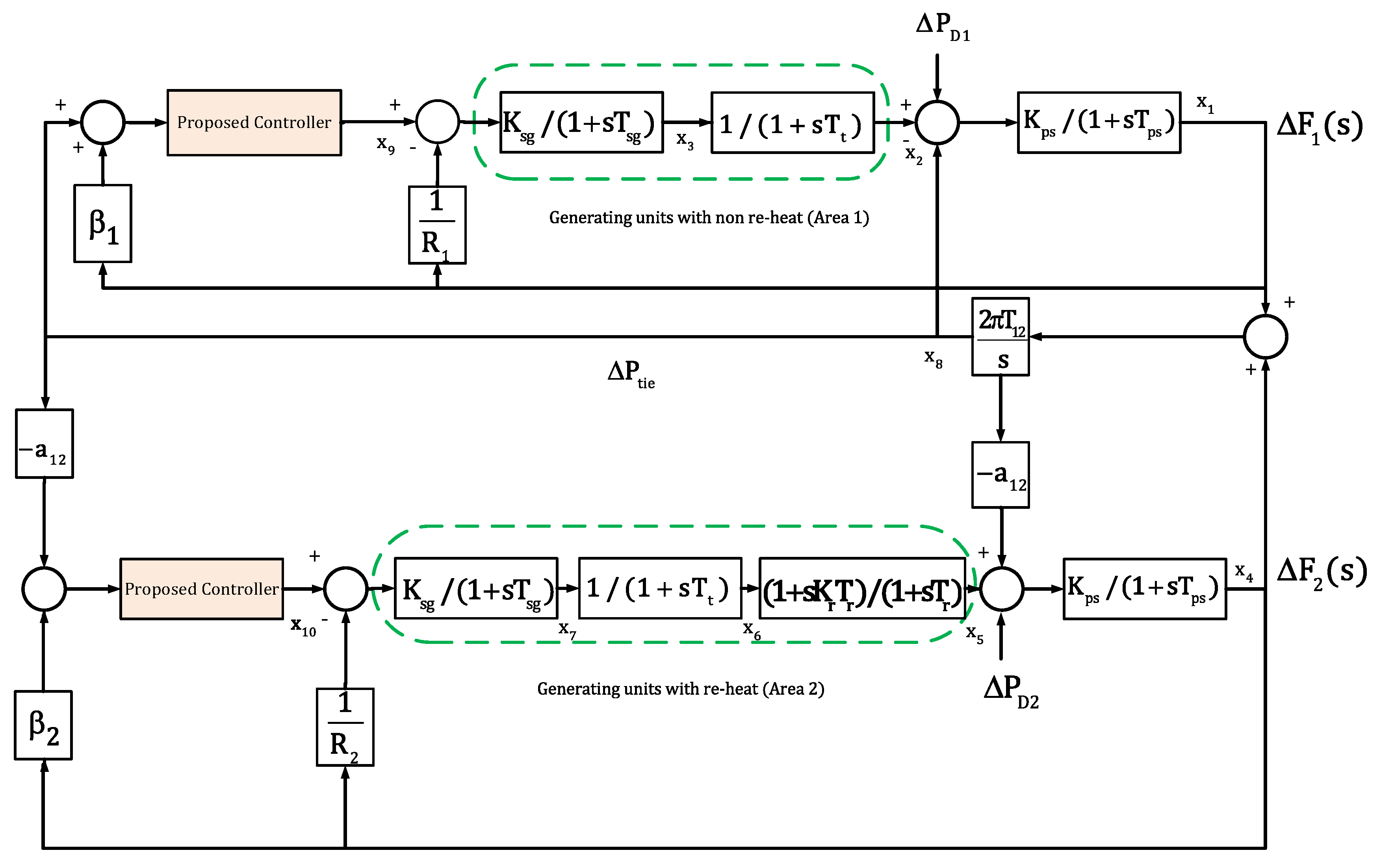
Block diagrams of the proposed method and two-area power system are shown in Figure 5 and Figure 6, respectively.
According to Figure 6, the state-space model is described by the linear vector differential Equations [12]:
x ˙ = A x + B u + G w
where A, B and G are the system, input and disturbance matrices, respectively. The system matrix calculations are given in Appendix A. Matrices B and G are described in Equations (26) and (27), and x = [ Δ f 1 Δ P t 1 Δ X g 1 Δ f 2 Δ P r Δ P t 2 Δ X g 2 Δ P t i e Δ P c 1 Δ P c 2 ] , u = [ Δ u 1 Δ u 2 ] T , w = [ Δ P d 1 Δ P d 2 ] T are the state variables, input vectors and disturbance vectors.
The state-space model of the thermal power plant in a single area is as follows:
x ˙ 1 x ˙ 2 x ˙ 3 = 1 T s g 0 1 R T s g 1 T t 1 T t 0 0 K p s T p s 1 T p s x 1 x 2 x 3 + 1 T s g 0 0 u + 0 0 K p s T p s
x ˙ 1 x ˙ 2 x ˙ 3 x ˙ 4 = 1 T p s K p s T p s 0 0 0 1 T r ( 1 T r K r T t ) K r T t 0 0 1 T t 1 T t 1 R T s g 0 0 1 T s g x 1 x 2 x 3 x 4 + 0 0 0 1 T s g u + K p s T p s 0 0 0 w
For areas 1 and 2, the state-space model of the interconnected power system is defined as follows. System matrix, A, is described in Appendix A.
B = 0 0 1 T s g 1 0 0 0 0 0 0 0 0 0 0 0 0 0 1 T s g 2 0 0 0 T
G = K p s 1 T p s 1 0 0 0 0 0 0 0 0 0 0 0 0 K p s 2 T p s 2 0 0 0 0 0 0 T

4. Simulation Results

4.1. First Test System: Two-Area Power System

In this section, simulation is performed to illustrate the improved performance of our proposed controller compared to PI, PID and IMC-PID controllers. The test system consists of an interconnected power system with two-areas: (a) non re-heat “area-1” and (b) re-heat “area-2”. System parameters and Nomenclature are shown in Table 1 and Table A1.
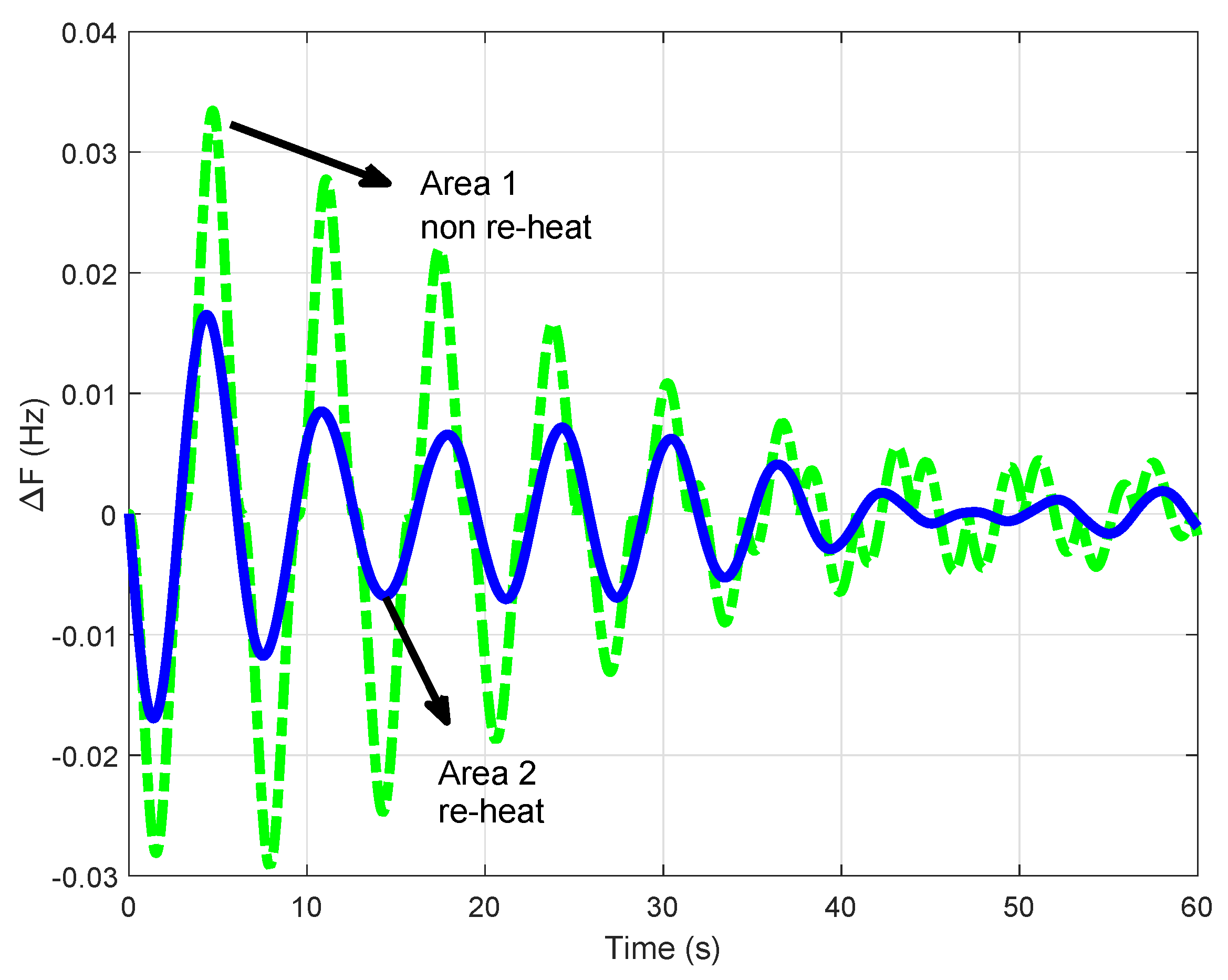
In this simulation, two disturbances of Δ P D 1 = 0.02 and Δ P D 2 = 0.03 are applied to areas 1, 2 of the system. Frequency deviations in areas 1,2 with the proposed controller are shown in Figure 7. As shown, the magnitudes of the frequency deviation in the areas 1, 2 are 0.04 and 0.05, respectively, which dies out very quickly and without any oscillations, while the frequency deviations with the PI controller are highly fluctuating as shown in Figure 8, which dies out only after about 60 s.
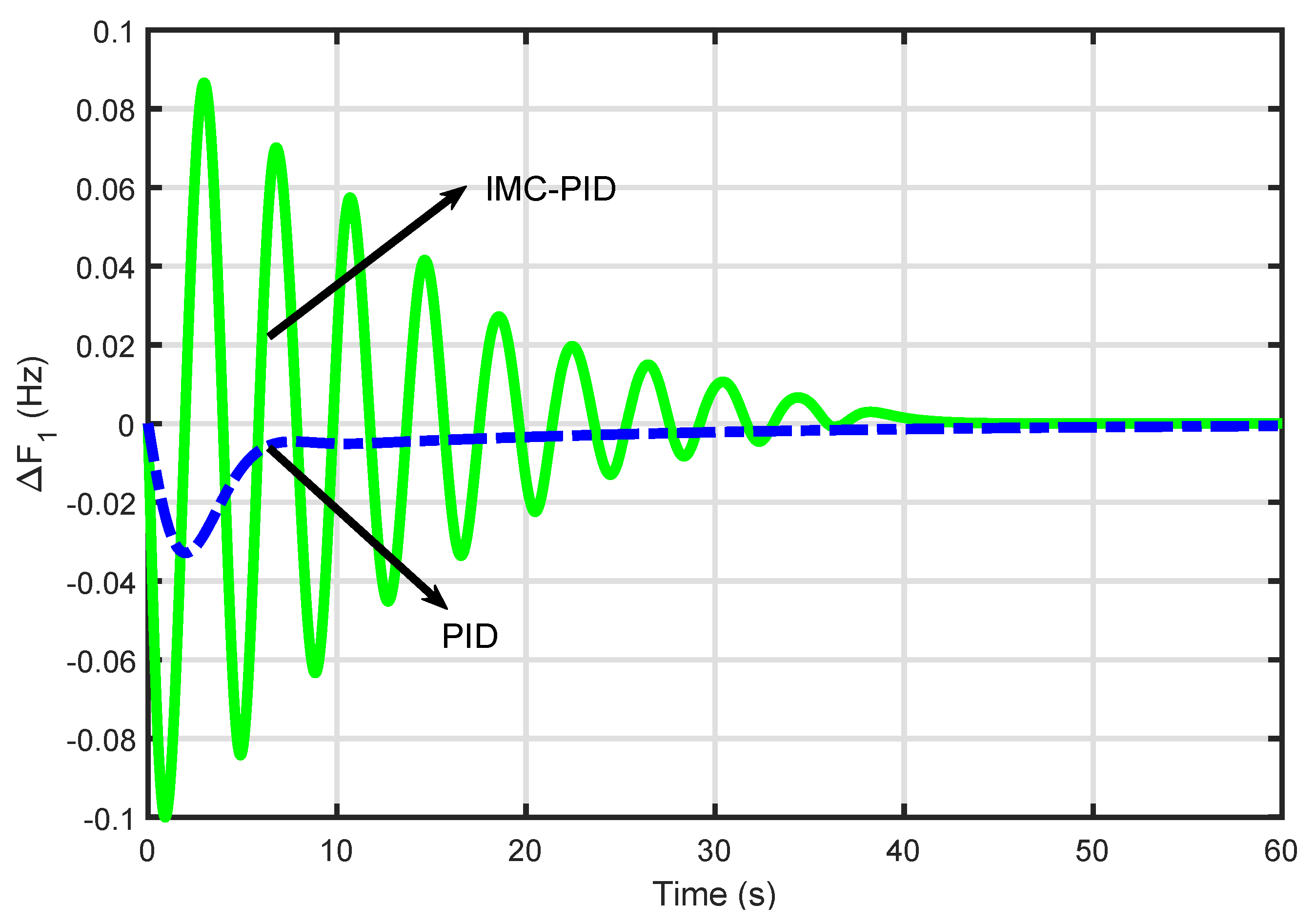
We additionally compare the performance of our proposed controller with an internal model controller based on PID (IMC-PID). For two-degree-of-freedom IMC-PID design, the transfer function of the power systems is approximated with a second-order model. The IMC-PID tuning procedure is as follows [35,36]:
  • Divide the system model into two parts:
    Φ ˜ ( s ) = Φ α ( s ) Φ β ( s )
    where Φ α ( s ) is the minimum-phase part, and Φ β is the non-minimum-phase part.
  • Design IMC controller for setpoint-tracking as follows:
    Ψ α ( s ) = Φ α 1 ( s ) × 1 ( η s + 1 ) n
    where η is a tuning parameter and n is the relative degree of Φ α ( s ) .
  • Design the IMC controller for disturbance-rejecting as follows:
    Ψ β ( s ) = λ 1 s + λ 2 s + + λ m s + 1 ( η β ( s ) + 1 ) m
    where η β is a tuning parameter for disturbance rejection, m is the number of poles of Φ ˜ ( s ) and λ 1 , λ 2 , , λ m should satisfy:
    ( 1 Φ ˜ ( s ) ) ( Ψ α ( s ) ( Ψ β ( s ) ) | s = φ 1 , φ 2 , , φ n = 0
    where φ 1 , φ 2 , , φ n are the poles to be omitted.
  • The Feedback controller is obtained using:
    M ( s ) = Ψ α ( s ) Ψ β ( s ) 1 Φ ˜ ( s ) Ψ α ( s ) Ψ β ( s )
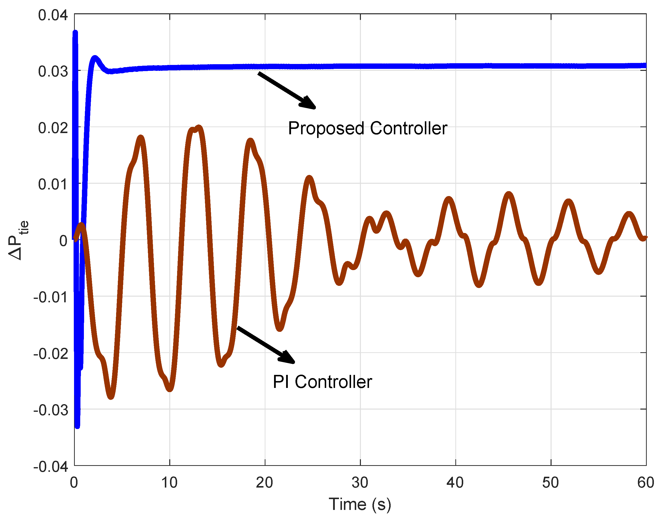
Then we use the Maclaurin series to tune the PID parameters by extending M ( s ) . The PID parameters of the IMC-PID controller are K p = 4.62 , K i = 6.23 and K d = 1.4 . The PID controller coefficients are tuned with a trial-and-error method. The simulation results are shown in Figure 9 and Figure 10. It can be seen from the frequency deviation response in cases a, b, c-I and c-II that the IMC-PID and PID controllers have more oscillations compared to our proposed controller. It is evident that the proposed method has less fluctuation and better performance than other controllers. Moreover, the control signals in areas 1 and 2 with our proposed controller and PI controller are shown in Figure 11 and Figure 12, respectively, where both number and frequency of oscillations in PI controller are larger compared to our proposed method. The power exchanges between the two-areas are shown in Figure 13. It can be seen that power changes reach a steady value after a drop without oscillation. Therefore, the proposed method shows a suitable transient response in the two-area system and reaches a steady-state with no fluctuation.

4.2. Second Test System: 39-Bus New England Test System

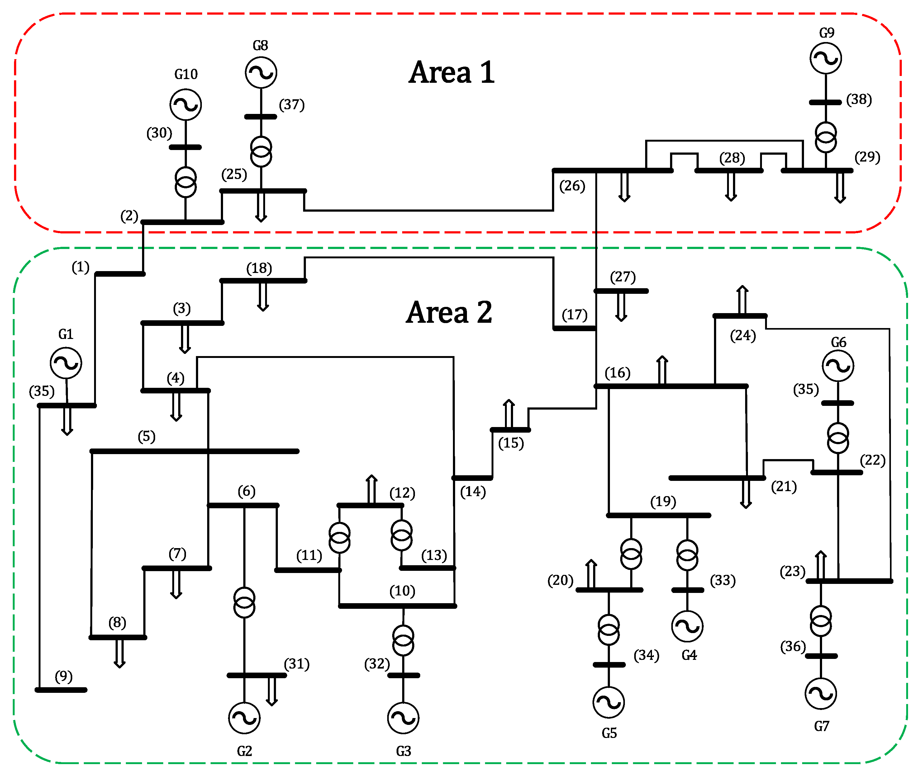
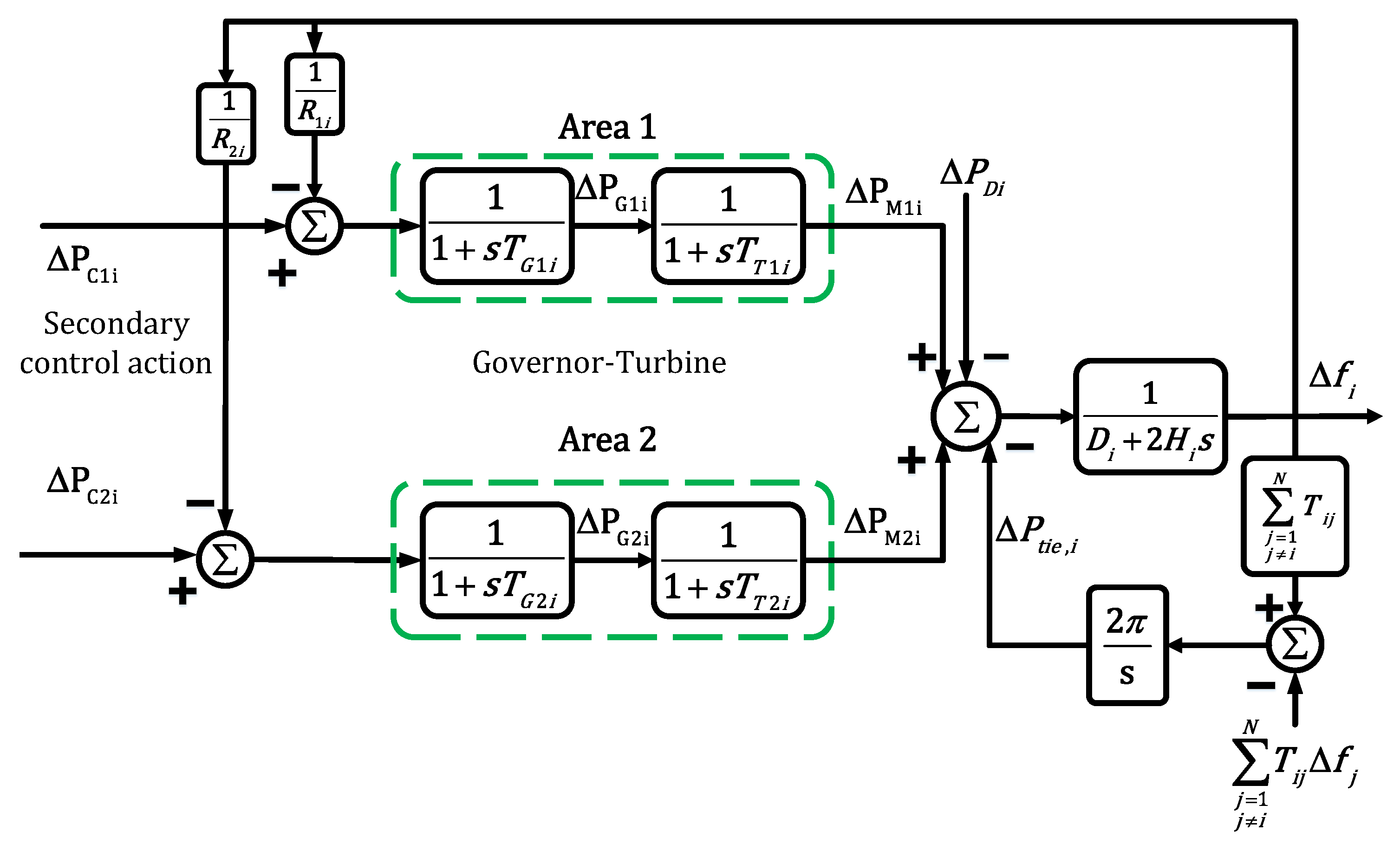
A large-scale multi-area interconnected power system consists of several control areas, connected by tie-line. Each area of multi-area power system includes a generator, governor, turbine and controller. For simulations in this section, the 39-bus New England test system is used, which is similar to the real-world power systems. For modeling, each area is considered to include a generator, governor and turbines. Then, for each area, a decentralized controller is designed where frequency control is performed by a generator. Moreover, a generator in each area is responsible for LFC. In this test system, G9 and G1 generators are responsible for LFC in areas 1 and 2, respectively. In this method, a speed governor system and four-stage steam is utilized. The speed governor system includes a proportional regulator, speed relay, and a servo motor. The steam turbine also includes a double re-heat model, modeled by first-order transfer functions [36]. The parameters of the steam turbine, buses, load and generators are given in [36,37].
Single-line diagram of 39-bus New England is shown in Figure 14, where it has 19 loads, 10 generators, 34 transmission lines and 12 transformers. There are 106.381 MW of conventional generation and 74.051 MW load in area 1. In area 2 there are 298.47 MW of conventional generation and 511.26 MW load. The main parameters of generator are given in [37]. Block diagram of control area i = 1 , 2 is presented in Figure 15. Parameters of control areas are given in Table 2.
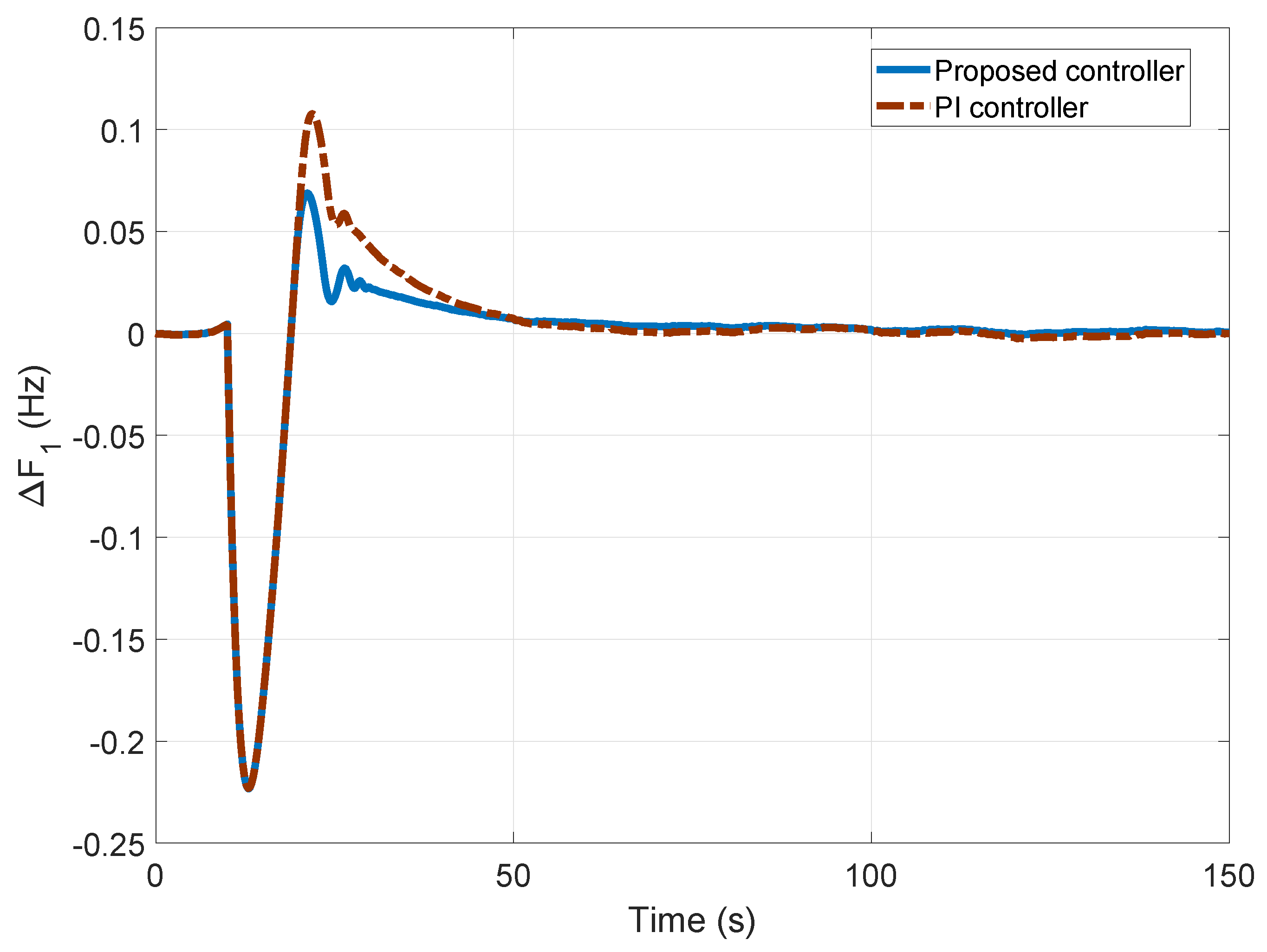
The simulation results by using the proposed and PI controllers are demonstrated in Figure 16 and Figure 17. As depicted in Figure 16 and Figure 17, the frequency deviations of areas 1 and 2 by proposed controller have very shorter settling time as well as overshoot than PI controller. The value of parameters of PI controllers are K p = 0.5 and K i = 0.125 , which are found using trial-and-error method.

5. Conclusions

A type-2 adaptive fuzzy controller is proposed in this paper, which increases the stability and reduces the uncertainties for the LFC caused by the nonlinearity and parametric uncertainties of power systems. Using MLP neural network structure, the Jacobian of system is applied online to the controller, and type-2 fuzzy controller is designed to reduce uncertainty. Then, the descent gradient and error back-propagation methods are used to train the network parameters. Further, a two-area system is tested with re-heating units and non re-heating. Additionally, the proposed method is characterized by versatility, real-time and computational reduction. Then, a PD controller is added to enhance the robustness of the system. The performance of the proposed controller has been compared with that of the conventional PID and internal model control based on PID (IMC-PID) controllers. Simulation results, performed on the IEEE New England 39-bus power system, indicate the superiority of our proposed method. For future studies, the proposed controller will be investigated by incorporation demand response programs in systems with large penetration of wind turbines.

Author Contributions

M.M. and S.Z.M. supervised the paper, A.D.S. wrote the paper, M.M. and L.V. checked and proofread the manuscript. All authors have read and agreed to the published version of the manuscript.

Funding

This research received no external funding.

Conflicts of Interest

The authors declare no conflict of interest.

Appendix A

x 1 = K p s 1 1 + s T p s 1 ( x 2 x 8 w 1 )
x 1 ˙ = 1 T p s 1 x 1 + K p s 1 T p s 1 x 2 K p s 1 T p s 1 x 8 K p s 1 T p s 1 w 1
x 2 = 1 1 + s T t 1 x 3
x 2 ˙ = x 3 T t 1 x 2 T t 1
x 3 = 1 1 + s T s g 1 ( u 1 x 1 R 1 )
x 3 ˙ = x 3 T s g 1 x 1 R 1 T s g 1 + u 1 T s g 1
x 4 = [ K p s 2 1 + s T p s 2 ] ( x 5 w 2 + a 12 x 8 )
x 4 ˙ = x 4 T p s 2 + K p s 2 T p s 2 x 5 K p s 2 T p s 2 w 2 + a 12 K p s 2 T p s 2 x 8
x 5 ˙ = 1 T r x 5 + ( 1 T r K r T t 2 ) x 6 + K r T t 2 x 7
x 6 ˙ = x 6 T t 2 + x 7 T t 2
x 7 ˙ = x 7 T s g 2 + u 2 T s g 2 1 T s g 2 R 2 x 4
x 8 = 2 π T 12 s ( x 1 x 4 )
x 8 ˙ = 2 π T 12 ( x 1 x 4 )
x 9 ˙ = B 1 x 1 + x 8
x 10 ˙ = B 2 x 4 a 12 x 8
A = 1 T p s 1 K p s 1 T p s 1 0 0 0 0 0 K p s 1 T p s 1 0 0 0 1 T t 1 1 T t 1 0 0 0 0 0 0 0 1 R 1 T s g 1 0 1 T s g 1 0 0 0 0 0 0 0 0 0 0 1 T p s 2 K p s 2 T p s 2 0 0 a 12 K p s 2 T p s 2 0 0 0 0 0 0 1 T r ( 1 T r K r T t 2 ) K r T t 2 0 0 0 0 0 0 0 0 1 T t 2 1 T t 2 0 0 0 0 0 0 1 R 2 T s g 2 0 0 1 T s g 2 0 0 0 2 π T 12 0 0 2 π T 12 0 0 0 0 0 0 β 1 0 0 0 0 0 0 1 0 0 0 0 0 β 2 0 0 0 a 12 0 0
Table A1. Nomenclature.
NotationsFull Name
iSubscript referring to area i.
P r i Rating of ith generator in MW.
T t Time constant of turbine in s.
T s g Time constant of speed governor in s.
K p s , T p s Time constant and gain of power system, respectively.
K r , T r Re-heat coefficient and time constant, respectively.
T 12 Synchronizing coefficient.
R i Governor speed regulation parameter in Hz per p.u. MW.
Δ P t i e The tie-line power deviation.
Δ f i Frequency deviation.
Δ P D i Load demand deviation.
Δ P r Re-heat output deviation.
B i Frequency bias constant.

References

  1. Kumar, A.; Kumar, V. A novel interval type-2 fractional order fuzzy PID controller: Design, performance evaluation, and its optimal time domain tuning. ISA Trans. 2017, 68, 251–275. [Google Scholar] [CrossRef] [PubMed]
  2. Bhavanisankar, C.; Sudha, K.R. An adaptive technique to control the load frequency of hybrid distributed generation systems. Soft Comput. 2019, 23, 12385–12400. [Google Scholar] [CrossRef]
  3. Sabahi, K.; Ghaemi, S.; Pezeshki, S. Gain Scheduling Technique using MIMO Type-2 Fuzzy Logic System for LFC in Restructure Power System. Int. J. Fuzzy Syst. 2017, 19, 1464–1478. [Google Scholar] [CrossRef]
  4. Zeng, G.-Q.; Xie, X.-Q.; Chen, M.-R. An Adaptive Model Predictive Load Frequency Control Method for Multi-Area Interconnected Power Systems with Photovoltaic Generations. Energies 2017, 10, 1840. [Google Scholar] [CrossRef] [Green Version]
  5. Wang, N.; Zhang, J.; He, Y.; Liu, M.; Zhang, Y.; Chen, C.; Gu, Y.; Ren, Y. Load-Frequency Control of Multi-Area Power System Based on the Improved Weighted Fruit Fly Optimization Algorithm. Energies 2020, 13, 437. [Google Scholar] [CrossRef] [Green Version]
  6. Khuntia, S.R.; Panda, S. Simulation study for automatic generation control of a multi-area power system by ANFIS approach. Appl. Soft Comput. 2012, 12, 333–341. [Google Scholar] [CrossRef]
  7. Khezri, R.; Oshnoei, A.; Oshnoei, S.; Bevrani, H.; Muyeen, S.M. An intelligent coordinator design for GCSC and AGC in a two-area hybrid power system. Appl. Soft Comput. 2019, 76, 491–504. [Google Scholar] [CrossRef]
  8. Babahajiani, P.; Shafiee, Q.; Bevrani, H. Intelligent Demand Response Contribution in Frequency Control of Multi-Area Power Systems. IEEE Trans. Smart Grid. 2018, 9, 1282–1291. [Google Scholar] [CrossRef]
  9. Chibuikem Nnadozie, E.; Ukachukwu Oparaku, O. Adaptation of a Novel Fuzzy Logic Controller to a Hybrid Renewable Energy System. J. Energy Res. Rev. 2018, 1, 1–10. [Google Scholar] [CrossRef]
  10. Hoonchareon, N.; Ong, C.; Kramer, R.A. Implementation of an ACE1 decomposition method. IEEE Trans. Power Syst. Rev. 2002, 22, 757–761. [Google Scholar] [CrossRef]
  11. Yousef, H.A.; AL-Kharusi, K.; Albadi, M.H. Load Frequency Control of a Multi-Area Power System: An Adaptive Fuzzy Logic Approach. IEEE Trans. Power Syst. 2016, 29, 1822–1830. [Google Scholar] [CrossRef]
  12. Guha, D.; Prasad, P.K. Problem analysis in MW frequency control of an Interconnected Power system using sampled data technique. IJLTET 2013, 2, 54–62. [Google Scholar]
  13. Velusami, S.; Chidambaram, I.A. Decentralized biased dual mode controllers for load frequency control of interconnected power systems considering GDB and GRC non-linearities. Energy Convers. Manag. 2007, 48, 1691–1702. [Google Scholar] [CrossRef]
  14. Talaq, J.; Al-Basri, F. Adaptive fuzzy gain scheduling for load frequency control. IEEE Trans. Power Syst. 1999, 14, 145–150. [Google Scholar] [CrossRef]
  15. Juang, C.-F.; Lu, C.-F. Load-frequency control by hybrid evolutionary fuzzy PI controller. Proc. Inst. Electr. Eng. Gener. Trans. Distrib. 2006, 153, 196–204. [Google Scholar] [CrossRef]
  16. Liu, X.J.; Kong, X.B.; Deng, X.Z. Power system model predictive load frequency Control. In Proceedings of the American Control Conference, Monteal, QC, Canada, 27–29 June 2012; pp. 6602–6607. [Google Scholar]
  17. Rajesh, K.S.; Dash, S.S.; Rajagopal, R. Hybrid improved firefly-pattern search optimized fuzzy aided PID controller for automatic generation control of power systems with multi-type generations. Swarm Evol. Comput. 2019, 44, 200–211. [Google Scholar] [CrossRef]
  18. Niknam, T.; Khooban, M.H. Fuzzy sliding mode control scheme for a class of nonlinear uncertain chaotic systems. IET Sci. Meas. Technol. 2013, 7, 249–255. [Google Scholar] [CrossRef]
  19. Khooban, M.H.; Alfi, A.; Nazari Maryam Abadi, D. Teaching–learning-based optimal interval type-2 fuzzy PID controller design: A nonholonomic wheeled mobile robots. Robotica 2013, 31, 1059–1071. [Google Scholar] [CrossRef]
  20. Khooban, M.H.; Alfi, A.; Nazari Maryam Abadi, D. Control of a class of nonlinear uncertain chaotic systems via an optimal type-2 fuzzy PID controller. IET Sci. Meas. Technol. 2013, 7, 50–58. [Google Scholar] [CrossRef]
  21. Tan, T. Tuning of PID load frequency controller for power systems. Energy Convers. Manag. 2009, 50, 1465–1472. [Google Scholar] [CrossRef]
  22. Zhao, X.; Lin, Z.; Fu, B.; He, L.; Fang, N. Research on Automatic Generation Control with Wind Power Participation Based on Predictive Optimal 2-Degree-of-Freedom PID Strategy for Multi-area Interconnected Power System. Energies 2018, 11, 3325. [Google Scholar] [CrossRef] [Green Version]
  23. Pradhan, P.C.; Kumar Sahu, R.; Panda, S. Firefly algorithm optimized fuzzy PID controller for AGC of multi-area multisource power systems with UPFC and SMES. Eng. Sci. Technol. 2016, 19, 338–354. [Google Scholar]
  24. Khooban, M.H.; Niknam, T. A new intelligent online fuzzy tuning approach for multi-area load frequency control: Self adaptive modified bat algoritm. Electr. Power Energy Syst. 2015, 71, 254–261. [Google Scholar] [CrossRef]
  25. Zeynelgil, H.L.; Demiroren, A.; Sengor, N.S. The application of ANN technique to automatic generation control for multi-area power system. Electr. Power Energy Syst. 2002, 24, 345–354. [Google Scholar] [CrossRef]
  26. Rinaldi, G.; Cucuzzella, M.; Ferrara, A. Third order sliding mode observer-based approach for distributed optimal load frequency control. IEEE Control Syst. Lett. 2017, 1, 215–220. [Google Scholar] [CrossRef]
  27. Pappachen, A.; Peer Fathima, A. Load frequency control in deregulated power system integrated with SMES–TCPS combination using ANFIS controller. Electr. Power Energy Syst. 2016, 82, 519–534. [Google Scholar] [CrossRef]
  28. Cong, S.; Li, G.; Ji, B. A Novel PID-LIKE Neural Network Controller. IFAC Proc. Vol. 2005, 38, 121–126. [Google Scholar] [CrossRef]
  29. Jin, W.; Wenzhong, G.; Shusheng, G.; Fuli, W. PID-like controller using a modified neural network. Int. J. Syst. Sci. 1997, 28, 809–815. [Google Scholar] [CrossRef]
  30. Lutfy, O.F.; Mohd Noor, S.B.; Marhaban, M.H.; Abbas, K.A. A Simplified PID-like ANFIS Controller Trained by Genetic Algorithm to Control Nonlinear Systems. Aust. J. Basic Appl. Sci. 2010, 4, 6331–6345. [Google Scholar]
  31. Dokht Shakibjoo, A.; Moradzadeh, M.; Moussavi, S.Z.; Afrakhte, H. Online Adaptive Type-2 Fuzzy Logic Control for Load Frequency of Multi-Area Power System. J. Intell. Fuzzy Syst. 2019, 37, 1033–1042. [Google Scholar] [CrossRef]
  32. Khanesar, M.A.; Teshnehlab, M.; Kayacan, E.; Kaynak, O. A novel type-2 fuzzy membership function: Application to the prediction of noisy data. In Proceedings of the IEEE International Conference on Computational Intelligence for Measurement Systems and Applications, Taranto, Italy, 6–8 September 2010. [Google Scholar]
  33. Sabahi, K.; Ghaemi, S.; Pezeshki, S. Application of type-2 fuzzy logic system for load frequency control using feedback error learning approaches. Appl. Soft Comput. 2014, 21, 1–11. [Google Scholar] [CrossRef]
  34. John, R.; Castillo, O.; Hagras, H. Type-2 Fuzzy Logic and Systems; Springer: London, UK, 2018. [Google Scholar]
  35. Tan, W. Unified tuning of PID load frequency controller for power systems via IMC. IEEE Trans. Power Syst. 2010, 25, 341–350. [Google Scholar] [CrossRef]
  36. Report, I.C. Dynamic Models for Steam and Hydro Turbines in Power System Studies. IEEE Trans. Power Appar. Syst. 1973, 92, 1904–1915. [Google Scholar] [CrossRef]
  37. Bevrani, H.; Daneshfar, F.; Daneshmand, R.P. Intelligent Power System Frequency Regulations Concerning the Integration of Wind Power Units. In Wind Power Systems. Green Energy and Technology; Wang, L., Singh, C., Kusiak, A., Eds.; Springer: Berlin/Heidelberg, Germany, 2010. [Google Scholar]
Figure 1. MLP structure for system modeling [31].
Energies 13 02125 g001
Figure 2. The block-diagram of Type-2 Neuro-Fuzzy system.
Energies 13 02125 g002
Figure 3. Type-2 fuzzy structure.
Energies 13 02125 g003
Figure 4. The flowchart of the proposed method.
Energies 13 02125 g004
Figure 5. The proposed control structure.
Energies 13 02125 g005
Figure 6. Two-area load frequency control (re-heat and non re-heat).
Energies 13 02125 g006
Figure 7. Frequency deviation in areas 1 and 2 with the proposed controller (case a).
Energies 13 02125 g007
Figure 8. Frequency deviation in areas 1 and 2 with PI controller (case b).
Energies 13 02125 g008
Figure 9. Frequency deviation in area 1 with the IMC-PID and PID controllers (case c-I).
Energies 13 02125 g009
Figure 10. Frequency deviation in area 2 with the IMC-PID and PID controllers (case c-II).
Energies 13 02125 g010
Figure 11. Control signal in areas 1 and 2 with our proposed controller.
Energies 13 02125 g011
Figure 12. Control signal in areas 1 and 2 with PI controller.
Energies 13 02125 g012
Figure 13. Deviation of the tie-line power with the proposed and PI controllers.
Energies 13 02125 g013
Figure 14. Single-line diagram of 39-bus New England with two areas.
Energies 13 02125 g014
Figure 15. Block diagram of control area i = 1 , 2 for 39-bus test system.
Energies 13 02125 g015
Figure 16. Frequency deviation in area 1 with proposed controller and PI controller.
Energies 13 02125 g016
Figure 17. Frequency deviation in area 2 with proposed controller and PI controller.
Energies 13 02125 g017
Table 1. Numerical Data.
NotationsNumerical Value
P r i 2000 MW
T t 0.3 s
T s g 0.08 s
K p s , T p s 120 s, 20 s
K r , T r 0.5 s, 10 s
T 12 0.545/2 π
R i 1/2.4
B i 0.425
K d 0.4
a 12 1
η −0.81
Table 2. Parameters of control area i = 1 , 2 for 39-bus test system.
Full NameValue
Governor time constant ( T G i ) [s]0.07
Turbine time constant ( T T i ) [s]0.001
Load change in area i ( Δ P D i ) 0.9
Load damping coefficient ( D i )1
Equivalent inertia constant ( H i )2.35
Tie-Line synchronizing torque coefficient ( T 12 ) [s]0.02
Speed-droop charateristic (R)0.05