Article

Increasing the Device Performance of Recycling Double-Pass W-Ribs Solar Air Heaters

Department of Chemical and Materials Engineering, Tamkang University, Tamsui, New Taipei 251, Taiwan
*
Author to whom correspondence should be addressed.
Energies 2020, 13(9), 2133; https://doi.org/10.3390/en13092133
Submission received: 17 February 2020 / Revised: 16 April 2020 / Accepted: 24 April 2020 / Published: 28 April 2020
(This article belongs to the Section A2: Solar Energy and Photovoltaic Systems)

Abstract

:
The device performance of recycling double-pass solar air heaters with W-ribs by machining on both sides of the absorber plate is investigated experimentally and theoretically. It is emphasized that in comparing various design configurations, they should be compared for the increase of power consumption suffered by the air passing through the collector under the same air mass flow rate and working dimensions. Compared to those of the single-pass and flat-plate double-pass device, both effects of the external recycle and the artificial W-ribs by machining enhance the collector thermal efficiency in this study. This study proposes an optimal design of the recycling W-ribs double-pass device that is expected to consider the compensation between collector thermal efficiency improvement I W due to the external recycle and the increase of power consumption I P , W owing to pumping the air circulation in the two divided subchannels. The evaluation of a higher ratio of I W to I P , W leads to economic benefits. It has been observed that a relative higher ratio of collector thermal efficiency improvement to the increase of power consumption occurs at recycle ratio R = 0.5. The results indicated the turbulent intensity increment with the artificial W-ribs by machining on both sides of the absorber plate could compensate for the increase of power consumption with the consideration of economic feasibility. The operation of a recycling W-ribs solar air heater with two covers in a double-pass mode offers an inexpensive method of improving the collector thermal efficiency by about 76.65%. The advantage of the present device is evident and provides a feasible design to improve the solar air heater of which the promotion in turbulence effectively raises the convective heat-transfer coefficient. The collector thermal efficiency enhancement of the double-pass operation is much higher than that in the smooth plate under different recycle ratios and mass flow rates.

Graphical Abstract

1. Introduction

The collector thermal efficiency of a conventional solar air heater (SAH) is known to be less ideal due to a low convective heat-transfer coefficient between the heating surface and flowing fluid widely used in space heating [1], drying food products [2], and some industrial technologies [3]. The performance of a SAH device could be effectively enhanced by increasing the convective heat-transfer coefficient. An energy efficient solar air collector is a device which receives the incoming solar radiation by the absorber plate, and delivers the thermal energy to heat the fluids flowing through the collector. The major concerns are the materials of coating on the absorber plate, selective absorber plate surfaces, heat transfer characteristic with minimum losses at each step, and several different designing principles. The principal requirements are an extended contact area [4] between the absorber plate surface and the flowing air, the flow turbulence with vortex generators [5,6], packing wire mesh [7], and v-grove [8] to attain a higher heat transfer coefficient. A potential strategy includes breaking the laminar sublayer in the turbulent boundary layer region to destroy viscous laminar sublayer adjacent to the absorber plate by using corrugated/grooved absorber surfaces is also an alternative [9]. Moreover, it is desirable that the turbulence created only close to the heat transfer surface where the heat exchange takes place and the flow should not be excessively disturbed to avoid additional power consumption. External recycling with air recirculation produces an effect of remixing the inlet air with hot outgoing air upon increasing the fluid velocity with convective heat-transfer coefficients. Heat transfer models are examined for such double- or multi-pass operations, and compared with the collector thermal efficiency of the single-pass device. The concept of designing the double-pass device of solar air heaters proposed by Satcunanathan and Deonarine [10] is the air circulation to be heated twice in two subchannels before exiting the collector. The inlet air was mixed and preheated with the hot exiting air from the upper subchannel before flowing through the bottom subchannel under recycling operations in the present study. In such conditions, the thermal performance is enhanced with the technical practicability in double-pass [11] and multi-pass [12] operations, as well as the double-pass design with external recycle [13,14]. To make the solar air collector more efficient thermal energy utilization design, collector thermal efficiency needs to be improved by implementing various flow configurations and using a different artificial roughness geometry on absorber plates [15]. A new device in this study includes both desirable effects in raising the turbulence intensity enhancement within artificial roughness of W-ribs by machining [16] on both sides of the flat-plate absorber and operating double-pass devices with external recycle. Figure 1 conceptualizes this device with external recycle. The multiplied of turbulent flow channels of solar air collector were examined to have enhanced the thermal performance due to both sides of the absorber plate having the artificial roughness of W-ribs. The artificial W-ribs as a roughness element creates the turbulence in the flow channel, thereby resulting in the broken laminar sublayer and the enhanced thermal performance of SAH. However, the thermal performance is accompanied by power consumption increments owing to the friction loss brought about by fixing the artificial W-ribs in the flow channel [17]. The power penalty with increasing friction loss must be taken into account given that the power supply requirement also increases [18]. Hence, the selection of the particular ribs geometry provides the advantage from an economic viewpoint that optimizes the thermal performance with consideration of both the heat-transfer efficiency enhancement and power consumption increment.
This present study is actually the extension of our previous work [19], by replacing the flat-plate absorber with the machining artificial W-ribs on both sides of the absorber plate. Though the heat transfer mechanism in this W-ribs device could most analogized from that of the previous work [19], the manners of transport through the collector are somewhat different. The purposes of the present study include the following three aspects. First, the device performance of the recycling double-pass W-ribs solar air collector is examined via a graphical presentation for comparisons. Second, the influences of solar irradiation on the absorbing surface and impact of temperature variation of the inlet air on the thermal enhancement (due to the turbulence the artificial W-ribs by machining creates on both sides of the absorber plate) are evaluated. Third, the effects of the recycle ratio and air mass flow rate are characterized by the collector thermal efficiency and the increase of power consumption.
The remainder of the paper is organized as follows. In Section 2, the theoretical model and formulation is laid out, including a description of collector thermal efficiency. Section 3 presents the experimental steps and visualizes the methods. Section 4 elaborates on the collector efficiency and power consumption, where the drivers enhancing the device performance are emphasized. Section 5 presents and discusses the results. Section 6 concludes the main findings.

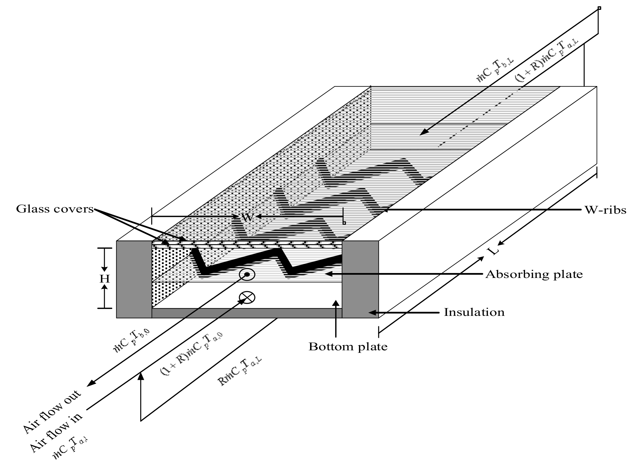
2. Theoretical Formulations

The heat transfer characteristic in a parallel conduit of total height 2 H , length L , and width w , as shown in Figure 1, with the inlet air entering at the lower subchannel was considered. While the theoretical analysis of the collector thermal efficiency is similar to the mathematical formulation generated in our existing research contribution [19]. The assumptions are applied as follows: (1) steady-state one-dimensional temperature distributions; (2) glass covers and flowing fluid do not absorb radiant energy, and (3) the thermal radiation of the insulation of all outside surfaces, except glass covers, are assumed to be negligible. The energy balance was derived in Equation (1) for the inner cover while the radiant energy absorbed by the outer glass cover with a thickness of 2.3 mm was found to be negligible by Duffie and Beckman [20].

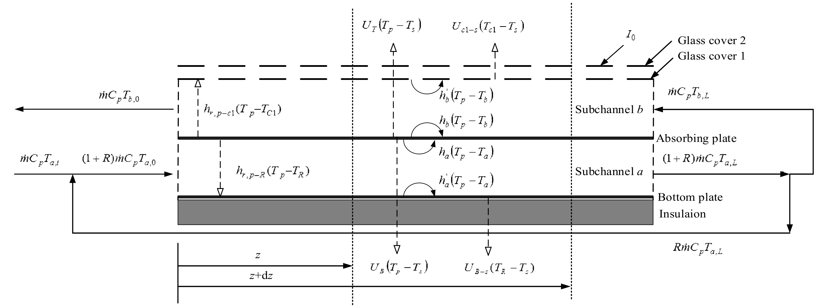
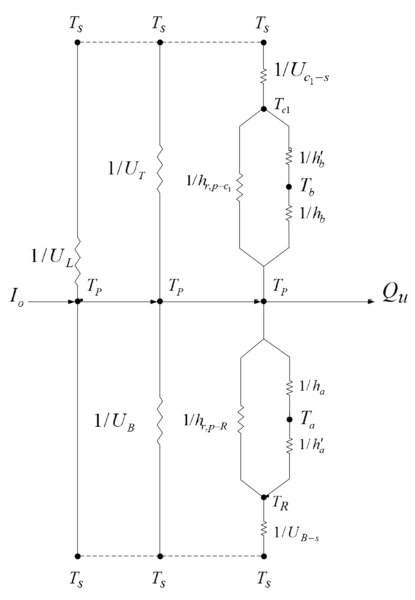
2.1. Energy Balance Equations

Making energy balances for the absorbing plate, the glass cover, the bottom plate, and the air flowing into both subchannels, as shown in Figure 2, can be written for the flow configuration with a finite system element of average width w and a differential thickness dz at a distance z from the inlet.
h r , p c 1 T P T c 1 + h b ' T b ( z ) T c 1 U c 1 s T c 1 T s = 0
I o α p τ g 2 U T T P T s U B T P T s h b T P T b ( z ) h a T P T a ( z ) = 0
h r , p R T P T R + h a ' T a ( z ) T R U B s T R T s = 0
m ˙ ( 1 + R ) C p d T a ( z ) = h a T P T a ( z ) w d z h a ' T a ( z ) T R w d z ,   the   lower   subchannel
m ˙ C p d T b ( z ) = h b T P T b ( z ) w d z h b ' T b ( z ) T c 1 w d z ,   the   upper   subchannel  
The radiation and heat transfer coefficients in Equations (1)–(3) are calculated by the following empirical expression. Klein [21] developed an empirical expression for U T [22,23]:
U T = N C P T p , m ( T p , m T s ) N + f e + 1 h w 1 + σ ( T p , m + T s ) ( T p , m 2 + T s 2 ) ( ε p + 0.00591 N h w ) 1 + 2 N + f 1 + 0.133 ε p ε g N
where
f = ( 1 + 0.089   h w 0.1166   h w ε p ) ( 1 + 0.07866   N )
C P = 520 ( 1 0.00005 β 2 )   for   0 < β < 70 ;   for   β > 70   use   β = 70
e = 0.43 ( 1 100 / T p , m )
The thermal resistance from the inner cover through the outer cover to the ambient air, could be expressed as [19]
1 U c 1 s = 1 h w + h r , c 2 s + 1 h c 1 c 2 + h r , c 1 c 2 = 1 ( 2.8 + 3.0   V ) + ε g σ ( T c 2 , m 2 + T s 2 ) ( T c 2 , m + T s ) + 1 1.25 ( T c 1 , m T c 2 , m ) 0.25 + σ ( T c 1 , m 2 + T c 2 , m 2 ) ( T c 1 , m + T c 2 , m ) ( 1 / ε g ) + ( 1 / ε g ) 1
Moreover, the forced convective heat-transfer coefficient for air flowing in both subchannels with machining artificial W-ribs could be estimated by following the Dittus–Boelter equation [24]
N u , i = h i D e , i / k = 2 × 0.024 . Re i 0.8   Pr 0.4 ,   6900 < Re i < 14000 ,   i = a , b , s
in which the characteristic length is equivalent to the diameter of the air flow channel:
D e , s = 4 2 ( H ε ) W ) 2 2 ( H ε ) + W ) ,   D e , a = D e , b = 4 ( H ε ) W ) 2 ( H ε ) + W )
The average velocities of the lower and upper subchannels and the Reynolds numbers for the rectangular channels are
v s ¯ = m ˙ 2 ( H ε ) W ) ρ ,   v a ¯ = m ˙ ( 1 + R ) ( H ε ) W ) ρ ,   v b ¯ = m ˙ ( H ε ) W ) ρ
Re s = ρ v s ¯ D e , s μ ,   Re a = ρ v a ¯ D e , a μ ,   Re b = ρ v b ¯ D e , b μ

2.2. Analytical Solution Procedure

All the coefficients for various heat-transfer parts of the solar air heater are lumped into the thermal resistance network in Figure 3. By following the same procedure performed in our previous works [19,25,26] and rearranging Equations (1) and (2) with ξ = z / L , one obtains
d T b ξ T s d ξ = B 1 T b ξ T s + B 2 T a ξ T s + B 3
d T a ξ T s d ξ = B 4 T b ξ T s + B 5 T a ξ T s + B 6
The boundary conditions for solving Equations (12) and (13) are represented by:
ξ = 0 ,   T a ( 0 ) = T a , 0 = T i n + R T a ( 1 ) 1 + R
ξ = 1 ,   T a ( 1 ) = T a , L = T b , L
The analytical solutions to this device are obtained by converting Equations (12) and (13) into a pair of differential operator equations. The steady-state temperature distributions of these two subchannels are represented, respectively, as
T a ( ξ ) = C 1 e Y 1 ξ + C 2 e Y 2 ξ B 3 B 4 B 1 B 6 B 2 B 4 B 1 B 5 + T s
T b ( ξ ) = Y 1 B 5 B 4 C 1 e Y 1 ξ + Y 2 B 5 B 4 C 2 e Y 2 ξ + B 3 B 5 B 2 B 6 B 2 B 4 B 1 B 5 + T s
All the coefficients Bi, Gi, Yi, Ci and F were in terms of the convective heat-transfer coefficients, loss coefficients and physical properties, as listed in Appendix A.

2.3. Collector Efficiency

Equation (17) was used to calculate the outlet temperature of T b , 0
T b ( 0 ) = T b , 0 = Y 1 B 5 B 4 C 1 + Y 2 B 5 B 4 C 2 + B 3 B 5 B 2 B 6 B 2 B 4 B 1 B 5 + T s
The energy balance was made on the whole solar air heater, including both subchannels with the specified inlet and outlet temperatures, to estimate the useful energy acquired by the air flow
Q u = m ˙ ( 1 + R ) C p ( T a , L T a , 0 ) + m ˙ C p ( T b , 0 T b , L ) = m ˙ C p ( T b , 0 T a , i )
Incorporating the actual useful energy gain to the incident solar radiation yields the collector thermal efficiency of the recycling double-pass W-ribs solar air heater
η W = Q u ( Useful   gain   of   energy   carried   away   by   air ) I 0 A c ( Total   solar   radiation   incident ) = m ˙ C p ( T b , 0 T a , i ) I 0 A c = I 0 τ g 2 α p U L ( T p , m T s ) I 0
The average absorber temperature is readily obtained by equating the terms on the right-hand side of Equation (20):
T p , m = T s + ( I 0 τ g 2 α p / U L ) m ˙ C p ( T b , 0 T a , i ) A c U L
= T s + ( I 0 / U L ) ( τ g 2 α p η W )
The total heat loss to the surrounding is obtained by summing the loss from the top, edge, and bottom:
Q loss = U L A c ( T p , m T s ) = U T A c ( T p , m T s ) + U B A c ( T R , m T s ) + U E A E ( T a , m + T b , m 2 T s )
where the average temperatures T R , m , T a , m , T b , m and T p , m can be obtained by integrating and rearranging Equations (3), (16), (17), and (21). Meanwhile, U T , U B , and U E are estimated by Equations (6) and (23), respectively. The edge and bottom loss coefficients depend primarily on level of insulation thickness:
U B = U E = k s / l s
The collector thermal efficiency improvements, say I D and I W , are evaluated by defining the percentage of the improvement within the collector thermal efficiency of the double-pass flat-plate device and the present recycling double-pass W-ribs device (compared to the downward-type single-pass device) under the same working dimensions as
I D = collector   thermal   efficiency   of   flat - plate   double - pass   device   ,   η D collector   efficiency   of   downward   sin gle - pass   device ,   η S 1
I W = collector   thermal   efficiency   of   double - pass   W - ribs   device   ,   η W collector   thermal   efficiency   of   downward   sin gle - pass   device ,   η S 1
in which η D , η W , and η S denote collector thermal efficiencies of the double-pass flat-plate, double-pass W-ribs, and downward-type single-pass devices, respectively.
The further collector thermal efficiency enhancement E W in collector thermal efficiency by machining artificial W-ribs absorber plate in the flow channel is calculated basing on the device of the same working dimensions as in the device with the flat-plate absorber:
E W = η W η D η D = [ ( η W η s ) ( η D η s ) η s ] ( η s / η D ) = ( I W I D ) ( η s / η D ) = I W I D 1 + I D

2.4. Power Consumption

The recycling double-pass operation with machining artificial W-ribs on both sides of the absorber plate are defined as:
  l w f , i = 2 f F , i v ¯ i 2 L D e , i ,   i = a , b , s
  P W = m ˙ ( 1 + R ) 2 f F , a v ¯ a 2 L D e , a + m ˙ 2 f F , b v ¯ b 2 L D e , b
which is associated with the hydraulic dissipated energy and the increase of power consumption.
The friction factor value is derived from the modified Blasius equation [27]
  f F , i = 2 × 0.085 Re i 0.25 ,   6900 < Re i < 14000 ,   i = a , b , s
Incorporating the formulation in downward single-pass operation P S = m ˙ 𝓁 w f , s = 2 f F , s v ¯ 2 L / D e , s , the increases of power consumption for the double-pass W-ribs and double-pass flat-plate devices, respectively, are defined as
I P , W = P W P S P S   and   I P , D = P D P S P S

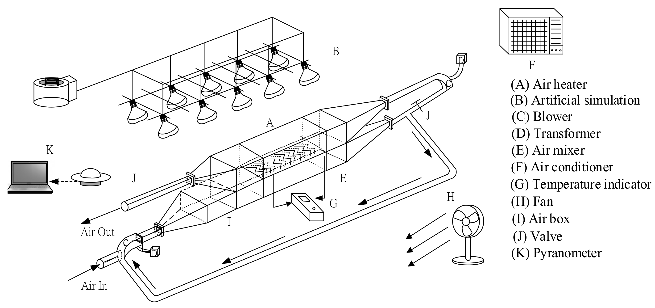
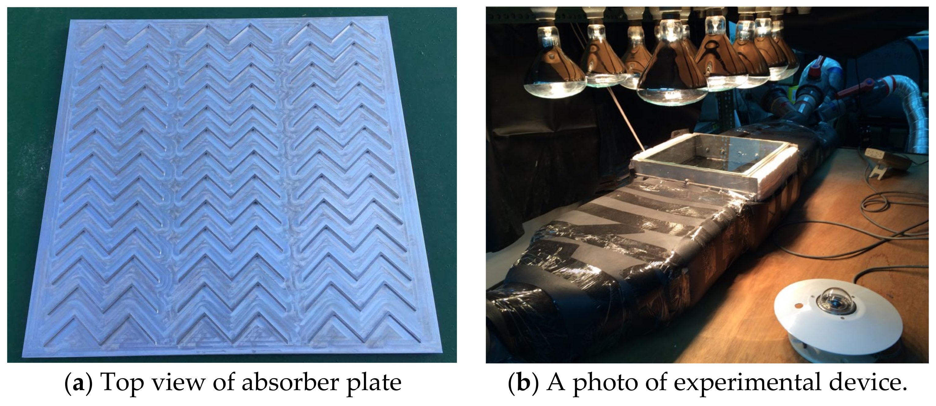
3. Experimental Methods and Apparatus

The configuration of double-pass W-ribs solar air heaters with artificial W-ribs by machining on both side of the absorber plate, which is of 7 × 10 5 m thickness for experimental runs to conduct recycling operations, is investigated theoretically and experimentally, as shown in Figure 4 and Figure 5 with a photo of the present experimental device. As shown in Figure 5, the soar collector (0.3 m long, 0.3 m wide, 0.05 m in height of each subchannel) has a double-layer glass cover to minimize heat losses from the collector (2.75 × 10 −3 m thickness and 0.05 m gap thickness between the inner cover and the absorber plate), a black absorber plate with machining artificial W-ribs, and the electrical power supplies (110 V, 125 W) for simulation and Styrofoam (0.06 m thickness) for thermal insulation. The collector has an inlet and outlet channel to pass the air above and under the absorber surface. The solar air heater is well thermally insulated to diminish the heat loss except for the outer glass cover. A blower (Teco 3 Phase Induction Motor) is employed to propel the air flowing above and under the absorber plate. The air mass flow rate is regulated by an adjustable valve and is measured using an anemometer (Kanmax Japan Inc., Osaka, Japan). The ambient temperature (Ts = (30 ± 0.1) °C) is measured at a position 0.15 m above the outer glass cover and is monitored using an air conditioner with a fan to provide wind flow at rate of 1.0 m/s. The incident solar radiation is specified and monitored for each experimental run and recorded with an Epply laboratory pyranometer and Instantaneous Solar Radiation meter (Model No. 455 from Epply Laboratory Inc.). The device parameters [18] and operation conditions are set at: L = w = 0.3 m; H = 0.062 m; ks = 46.64 W/m K; τ g = 0.875 ; α p = 0.95 ; ε g = 0.94 ; ε p = 0.8 ; ε R = 0.94 ; I 0 = 830   and   1100   W / m 2 ; T i n = 293 ,   303   and   313 K; V = 1.0   m / s ; m ˙ = 0.0107, 0.0161 and 0.0214 kg/s; T s = 293 K , σ = 5.68 × 10⁻⁸ W/m2K4.
The deviation between the experimental results and theoretical predictions is defined as:
E = 1 N exp i = 1 N exp η t h e o , i η exp , i η t h e o , i × 100 %
Experimental deviations from the theoretical formulation are then quantified and calculated by Equation (31) conditional on 0.73 % E 2.39 % , under two incident solar radiations for two devices without (flat-plate type) and with machining artificial W-ribs. A relatively good consistency between theoretical predictions and experimental results of collector thermal efficiency is reached in this regard.

4. Collector Thermal Efficiency and the Increase of Power Consumption

The following collector geometries (w, L, H), system properties (ks, τ g , α p , ε g , ε p , ε R , C p , μ , ρ ), and operating conditions ( I 0 , T i n , V , m ˙ , T s ) were specified first. The calculation procedures for theoretical predictions of collector thermal efficiency and collector thermal efficiency improvement are performed as follows. The initial guesses for the temperatures T p , m , T R , m , T c 1 , m , and T c 2 , m are estimated to obtain a temporary η W that is first estimated from Equation (20) using Equation (21a) for calculating T b , 0 when T p , m is assumed for a temporary value. The T p , m value is then re-checked using Equation (21b) by continuous iterations. The confirmed value η W is therefore obtained until the last calculated value meets the expected convergence. The collector thermal efficiency improvements of I D and I W for the recycling devices of the flat-plate and W-ribs absorbers are calculated in Equations (24) and (25). Both improvements are also listed in Table 1 for further comparisons. The further collector thermal efficiency enhancement E W decreases with the air mass flow rate and the recycle ratio, as shown in Table 1. It is observed that the considerable collector thermal efficiency improvement is further achieved when W-ribs absorber plate is fabricated for the purpose of raising the convective heat-transfer coefficient due to the increase in the turbulence intensity.

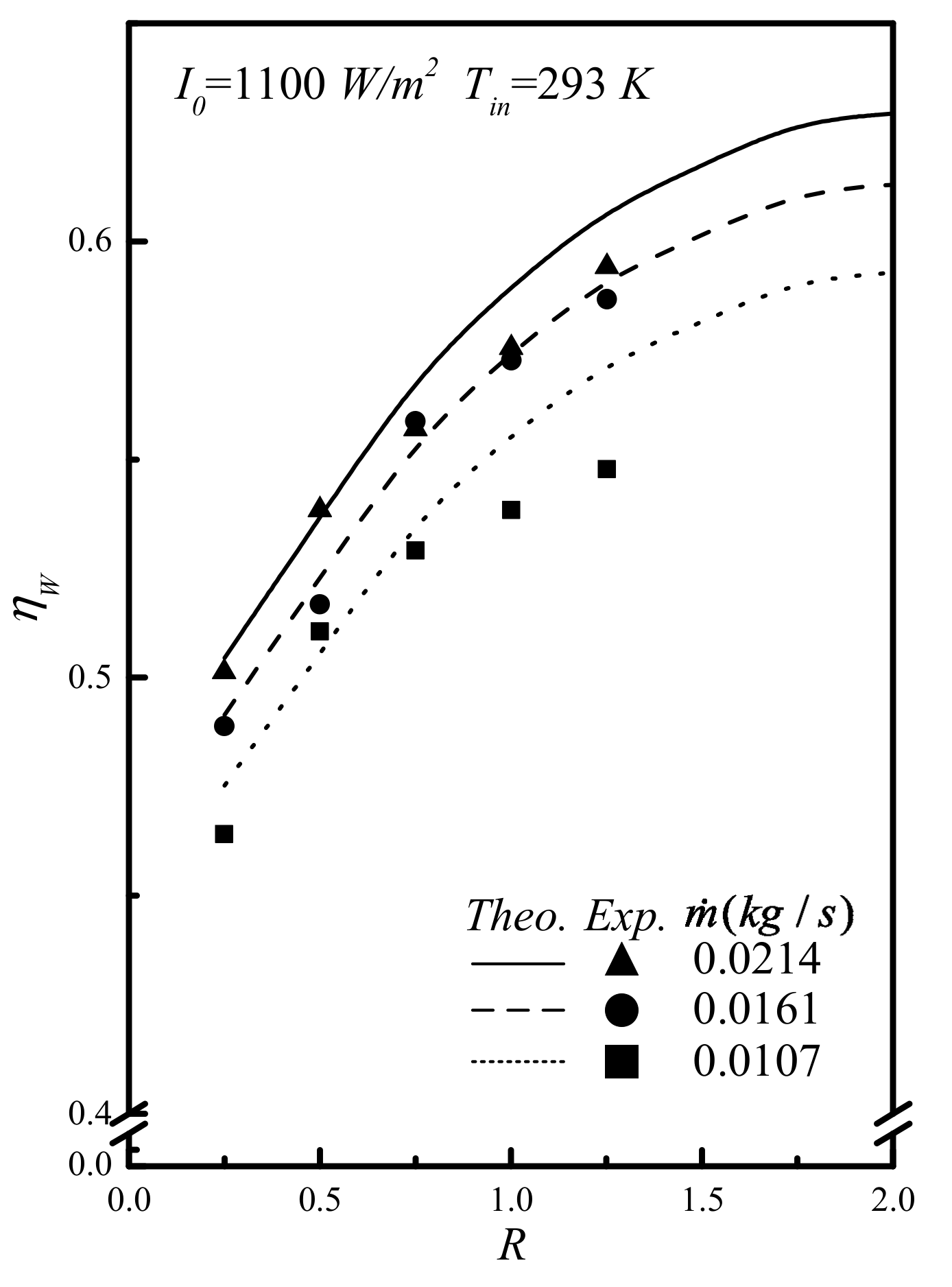
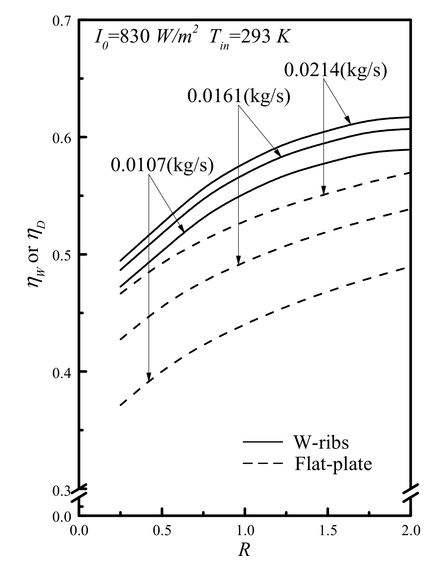
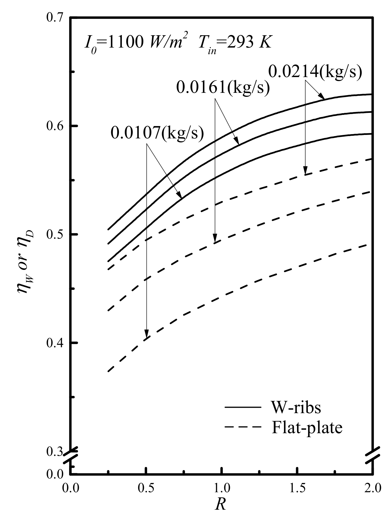
5. Results and Discussion

The calculation methods and procedure follow the earlier work [19]. The theoretical results and experimental runs of collector thermal efficiencies are obtained by substituting the values of physical properties and operation conditions in the corresponding equations. Figure 6 and Figure 7 present the graphical presentations for comparisons. The effects of recycling ratio on collector thermal efficiencies of theoretical results and experimental runs for various incident solar radiations, recycling ratios and air mass flow rates are presented in Figure 6 and Figure 7. The figures indicate that the collector thermal efficiency of the W-ribs solar air collector is higher than those of the flat-plate device. The collector thermal efficiency and its improvement increase with both the recycling ratio and incident solar radiation, but decrease with the air mass flow rate. Such a particular condition holds when the collector thermal efficiency improvement I W reaches 156.20% and 156.63% for I 0 = 830   and   1000   W / m 2 , respectively, under the lower air mass flow rate m ˙ = 0.0107   kg / s and higher recycle ratio R = 2, as indicated by Table 1.
The further collector thermal efficiency enhancement is accomplished if there are artificial W-ribs that are fabricated on both sides of the absorber plate for increasing the convective heat-transfer coefficient resulting from the turbulence increment. More than 76.65% improvement is achieved with artificial W-ribs by machining on both sides of the absorber plate rather than the same device of flat-plate type under I0 = 1100 W/m2, T a , i = 293 K, m ˙ = 0.0107   kg / s and R = 0.25 for example, as seen in Table 1.
All the theoretical predictions of η D and η W indicate that the collector thermal efficiencies increase with the air mass flow rate and incident solar radiations. But it increases with the recycle ratio in a more significant extent, as shown by Figure 8 and Figure 9 and Table 1 as well. This implies that under all air mass flow rates and recycle ratios, the W-ribs solar air collector functions better in improving the collector thermal efficiency than other recycling configurations of flat-plate solar air heaters do. To determine the suitable selections of the operating condition in achieving economic efficacy, the impacts of different recycle ratios and air mass flow rates on the ratio of collector thermal efficiency improvement and the increase of power consumption, specified as ( I D / I P , D and I W / I P , W ). The extent of collector thermal efficiency improvement is more remarkable than those in the flat-plate device. Thus, the higher value of I W / I P , W is obtained in operating recycling double-pass W-ribs solar air collectors, as illustrated in Figure 10. These findings showcase the advantage of such a recycling design with artificial W-ribs by the machining proposed by this study.
The introduction of external recycle has positive effects on the heat transfer rate, and hence, the collector thermal efficiency improvement under the larger recycle ratio and air mass flow rate. Outcomes assessment of collector thermal efficiency improvements requires the determination of some key operating parameters, such as air mass flow rate and recycle ratio. The collector thermal efficiency and collector thermal efficiency improvement increase with recycle ratio for a given air mass flow rate owing to the desirable effect of the forced convective heat-transfer coefficient increment. Meanwhile, increasing the air mass flow rate for a given recycle ratio will enhance the forced convective heat-transfer coefficient, and thus the collector thermal efficiency, but the further collector thermal efficiency enhancement occurs in reverse order. A suitable selection of the operating parameters for the recycling W-ribs solar air heater would be come out an evident advantage for practical applications with the economic sense. The quantity of interest is not I W alone, but the ratio of I W / I P , W . A more direct method is described herein for determining the recycle ratio for double-pass operations to be met with the higher value of I W / I P , W , which allows the specification set by the designer.

6. Conclusions

The application of operations with external recycle to the solar air heater has two conflicting effects: the positive effect of increasing air mass flow rate and the downside effect of decreasing the driving-force temperature difference caused by remixing the inlet air with the exiting air stream of a higher temperature. The beneficial aspect contributes to the convective heat-transfer coefficient increment while the opposite side leads to the heat-transfer rate decrement. The new design for improving the device performance of recycling double-pass W-ribs solar air heaters is reflected in the convective heat-transfer coefficient increased by either the turbulence intensity or the airflow velocity. Thus, the larger Nusselt number was achieved. The significant device performance improvement in terms of collector thermal efficiency is achieved through the machining artificial W-ribs rather than flat-plate device. Effects on the collector thermal efficiency of both the recycling operations and the artificial W-ribs by machining could be augmented by adjusting the recycle ratio, incident solar radiation, and air mass flow rate. Moreover, the further collector thermal efficiency enhancement of the recycling W-ribs device increases with the incident solar radiation but decreases with air mass flow rate and recycling ratio. The collector thermal efficiency improvement of artificial W-ribs by machining on both sides of the absorber plate compared to that of the flat-plate device is found to be 76.65%. Both effects on the collector thermal efficiency of recycling operations and artificial W-ribs by machining on both sides of the absorber plate could be augmented by increasing the recycle ratio, incident solar radiations, and air mass flow rates. This indicates that the collector thermal efficiency is well improved when the solar air collector uses the artificial W-ribs on both side of the absorber plate rather than using the flat-plate device.
The strategy of convective heat-transfer rate that fabricates W-ribs absorber plate with external recycle plays a notable role in operating the present solar air heater particularly when accounting for the economic implication. The ratio of I W / I P , W is represented in Figure 10 with the recycle ratio and air mass flow rate parameterizing the optimal operational condition. The main findings of this research are summarized as the following highlights: First, the recycling double-pass W-ribs solar air heater shows significant level of technical and economic feasibility for improving the device performance. Second, collector thermal efficiency improvements are found to increase with the recycle ratio and incident solar radiation and decrease with the air mass flow rate. Third, to meet the optimal level of operating conditions, the criterion for the ideal economic consideration of collector thermal efficiency improvements associated with the increase of power consumption should fall at R = 0.5. Overall, as the evident advantages documented in the findings of this study, the device of both recycling operation and artificial W-ribs by machining on both sides of the absorber plate improves the design of solar air heaters for current and future energy-smart generation.

Author Contributions

This paper is a result of the full collaboration of all the authors. However, the concept for this research was conceived by C.-D.H., H.C. elaborated the manuscript preparation, C.-C.H. and Y.-H.C. contributed to mathematical derivations, and Z.-S.H. performed the experiments. All authors have read and agreed to the published version of the manuscript.

Funding

This research received no external funding.

Acknowledgments

The authors would like to thank the Ministry of Science and Technology (MOST) of the Republic of China for the financial support.

Conflicts of Interest

The authors declare no conflict of interest.

Nomenclature

A c surface area of the collector (m2)
A E surface area of the edge (m2)
B i coefficients defined in Equations (A6)–(A13), i = 1, 2,…, 6
C i coefficients defined in Equations (A16) and (A17), i = 1, 2
C p specific heat of air at constant pressure (J/(kg K))
D e , i equivalent hydraulic diameter (m), i = a, b, s
e value equals 0.430 ( 1 100 / T p , m )
E deviation, defined in Equation (31)
E W further collector thermal efficiency enhancement, defined in Equation (26)
f empirical factor defined by Equation (7a)
f F , i Fanning friction factor defined in Equation (29), i = a, b, s
F coefficients derived in Equation (A18)
G i coefficients derived in Equations (A1)–(A7), i = 1, 2, …, 7
H height of channels (m)
h i convection coefficient in both subchannel, i = a, b (W/m2K)
h i convection coefficient under and above the absorber plate, i = a, b (W/m2K)
h c 1 c 2 convective coefficient between two glass covers (W/m2K)
h r , c 1 c 2 radiation coefficient between two glass covers, (W/m2 K)
h r , c 2 s radiation coefficient from the outer cover to the ambient (W/m2K)
h r , p c 1 radiation coefficient between the inner cover and absorber plate (W/m2 K)
h r , p R radiation coefficient between absorber plate and bottom plate (W/m2 K)
h w convective heat-transfer coefficient of the air flowing over the outer cover (W/(m2 K))
I 0 Incident solar radiation (W/m2)
I i coefficients, i = 1, 2
I D percentage of improvement defined in Equation (24)
I W percentage of improvement defined in Equation (25)
I P , D percentage of increment defined in Equation (30)
I P , W percentage of increment defined in Equation (30)
k thermal conductivity of the stainless steel plate (W/m K)
k s thermal conductivity of insulator (W/m K)
L channel length (m)
l s thickness of insulator (m)
𝓁 w f , i friction loss (J/kg), i = a, b, s
m ˙ air mass flow rate (kg/s)
N number of glass covers
N exp the number of the experimental measurements
N u , i Nusselt number, i = a, b, s
P D power consumption for the double-pass flat-plate device (W)
P S power consumption for the downward single-pass device (W)
P W power consumption for the double-pass W-ribs device (W)
P r Prandtl number
Q l o s s total heat loss to the surrounding (W)
Q u useful energy gain by flowing air (W)
R recycle ratio
R e i Reynolds number defined in Equation (11b), i = a, b, s
T a ( z ) axial fluid temperature distribution in the lower subchannel (K)
T a ( ξ ) dimensionless axial fluid temperature distribution of T a ( z ) (K)
T b ( z ) axial fluid temperature distribution in the upper subchannel (K)
T b ( ξ ) dimensionless axial fluid temperature distribution of T b ( z ) (K)
T a , 0 mixing temperature of the lower subchannel a at x = 0 (K)
T a , i inlet temperature of the lower subchannel (K)
T a , L outlet temperature of the lower subchannel at x = L (K)
T a , m average temperature of the lower subchannel (K)
T b , 0 temperature of the upper subchannel b at x = 0 (K)
T b , L temperature of the upper subchannel at x = L (K)
T b , m average temperature of the upper subchannel (K)
T c 1 temperature of the inner cover (K)
T c 2 temperature of the outer cover (K)
T c 1 , m average temperature of the inner cover (K)
T c 2 , m average temperature of the outer cover (K)
T i n inlet temperature of the lower subchannel (K)
T p temperature of W-ribs absorber plate (K)
T p , m average temperature of W-ribs absorber plate (K)
T R bottom plate temperature (K)
T R , m average temperature of bottom plate (K)
T s ambient temperature (K)
U B heat loss coefficient from the bottom plate to the ambient (W/m2 K)
U B s heat loss coefficient from the surfaces of edges and bottom to the ambient (W/m2 K)
U c 1 s heat loss coefficient from the inner cover to the ambient (W/m2 K)
U E heat loss coefficient from the edge (W/m2 K)
U L overall heat loss coefficient (W/m2 K)
U T heat loss coefficient from the top to the ambient (W/m2 K)
V wind velocity (m/s)
v i ¯ the average velocity defined in Equation (11a) (m/s), i = a, b, s
Y i coefficient defined in Equations (A14) and (A15), i = 1, 2
w collector width (m)
z axial coordinate along the flow direction (m)
Greek Letters
α p absorptivity of the absorber plate
β collector tilt (deg.)
η D collector thermal efficiency of the double-pass flat-plate device
η w collector thermal efficiency of the double-pass W-ribs device
η s collector thermal efficiency of the downward-type single-pass device
η exp , i experimental data of collector thermal efficiency
η t h e o , i theoretical prediction of collector thermal efficiency
τ g transmittance of glass cover
ε relative roughness
ε c 1 emissivity of inner cover
ε g emissivity of glass cover
ε R emissivity of bottom plate
ε p emissivity of absorbing plate
ρ air density (kg/m3)
μ air viscosity (kg/s m)
σStefan-Boltzmann constant (=5.682 × 10⁻⁸) (W/m2 K4)
ξ dimensionless channel position

Appendix A

The simultaneous system equations were derived in terms of all the coefficients Bi, Gi, Yi, Ci, and F with the convective heat-transfer coefficients, heat loss coefficients, and physical properties as follows:
G 1 = ( h a + U T + U B ) / ( U T + U B + h a + h b )
G 2 = h a / ( U T + U B + h a + h b )
G 3 = I 0 α p τ g 2 / ( U T + U B + h a + h b )
G 4 = ( h r , p c 1 + h b + U c 1 s ) 1
G 5 = ( h b + U T + U B ) / ( U T + U B + h a + h b )
G 6 = h b / ( U T + U B + h a + h b )
G 7 = ( h r , p R + h a + U B s ) 1
where
B 1 = W L ( h b G 1 + h b h r , p c 1 G 1 G 4 U c 1 s h b G 4 ) / m ˙ C p
B 2 = W L ( h b G 2 + h b h r , p c 1 G 2 G 4 ) / m ˙ C p
B 3 = W L ( h b G 3 + h b h r , p c 1 G 3 G 4 ) / m ˙ C p
B 4 = W L ( h a G 6 + h a h r , p R G 6 G 7 ) / ( 1 + R ) m ˙ C p
B 5 = W L ( h a G 5 + h a h r , p R G 5 G 7 U B s h a G 7 ) / ( 1 + R ) m ˙ C p
B 6 = W L ( h a G 3 + h a h r , p R G 3 G 7 ) / ( 1 + R ) m ˙ C p
The two distinct positive roots of two simultaneous linear ordinary differential equations (Equations (22) and (23)) are as follows:
Y 1 = ( B 1 + B 5 ) + ( B 1 B 5 ) 2 + 4 B 2 B 4 2
Y 2 = ( B 1 + B 5 ) ( B 1 B 5 ) 2 + 4 B 2 B 4 2
Substituting the boundary conditions, Equations (24) and (25), into Equations (22) and (23) gives the temperature distributions Equations (28) and (29), with the undetermined coefficients C 1 and C 2 as follows:
C 1 = 1 B 1 B 5 B 2 B 4 e Y 2 ( B 3 B 4 B 1 B 6 ) ( Y 2 B 4 B 5 ) + B 4 F ( 1 + R e Y 2 ) e Y 1 ( Y 1 B 4 B 5 ) ( 1 + R e Y 2 R ) e Y 2 ( Y 2 B 4 B 5 ) ( 1 + R e Y 1 R )
C 2 = 1 B 1 B 5 B 2 B 4 e Y 1 ( B 3 B 4 B 1 B 6 ) ( Y 1 B 4 B 5 ) + B 4 F ( 1 + R e Y 1 ) e Y 1 ( Y 1 B 4 B 5 ) ( 1 + R e Y 2 R ) e Y 2 ( Y 2 B 4 B 5 ) ( 1 + R e Y 1 R )
in which
F = B 3 ( B 4 B 5 ) + B 6 ( B 2 B 1 )

References

  1. Chen, X.; Yang, H.; Lu, L.; Wang, J.; Liu, W. Experimental studies on a ground coupled heat pump with solar thermal collectors for space heating. Energy 2011, 36, 5292–5300. [Google Scholar]
  2. El-Sebaii, A.A.; Shalaby, S.M. Experimental investigation of an indirect-mode forced convection solar dryer for drying thymus and mint. Energy Convers. Manag. 2013, 74, 109–116. [Google Scholar] [CrossRef]
  3. Chen, Z.; Gu, M.; Peng, D.; Peng, C.; Wu, Z. A numerical study on heat transfer of high efficient solar flat-plate collectors with energy storage. Int. J. Green Energy 2010, 7, 326–336. [Google Scholar] [CrossRef]
  4. Fudholi, A.; Sopian, K.; Othman, M.Y.; Ruslan, M.H.; Bakhtyar, B. Energy analysis and improvement potential of finned double-pass solar collector. Energy Convers. Manag. 2013, 75, 234–240. [Google Scholar] [CrossRef]
  5. Tamna, S.; Skullong, S.; Thianpong, C.; Promvonge, P. Heat transfer behaviors in a solar air heater channel with multiple V-baffle vortex generators. Sol. Energy 2014, 110, 720–735. [Google Scholar] [CrossRef]
  6. Skullong, S.; Promvonge, P.; Thianpong, C.; Pimsarn, M. Thermal performance in solar air heater channel with combined wavy-groove and perforated-delta wing vortex generators. Sol. Appl. Therm. Eng. 2016, 100, 611–620. [Google Scholar] [CrossRef]
  7. Nowzari, R.; Aldabbagh, L.B.Y.; Egelioglu, F. Single and double pass solar air heaters with partially perforated cover and packed mesh. Energy 2014, 73, 694–702. [Google Scholar] [CrossRef]
  8. Karim, M.A.; Perez, E.; Amin, Z.M. Mathematical modelling of counter flow v-grove solar air collector. Renew. Energy 2014, 67, 192–201. [Google Scholar] [CrossRef] [Green Version]
  9. Maithani, R.; Saini, J.S. Heat transfer and friction factor correlations for a solar air heater duct roughened artificially with V-ribs with symmetrical gaps. Exp. Therm. Fluid Sci. 2016, 70, 220–227. [Google Scholar] [CrossRef]
  10. Satcunanathan, S.; Deonarine, S. A two pass solar air heater. Sol. Energy 1973, 15, 41–49. [Google Scholar] [CrossRef]
  11. El-Sebaii, A.A.; Aboul-Enein, S.; Ramadan, M.R.I.; Shalaby, S.M.; Moharram, B.M. Investigation of thermal performance of double-pass flat and v-corrugated plate solar air heaters. Energy 2011, 36, 1076–1086. [Google Scholar] [CrossRef]
  12. Garg, H.P.; Sharma, V.K.; Bhargava, A.K. Theory of multiple-pass solar air heaters. Energy 1985, 10, 589–599. [Google Scholar] [CrossRef]
  13. Wijeysundera, N.E.; Ah, L.L.; Tjioe, L.E. Thermal performance study of two-pass solar air heaters. Sol. Energy 1982, 28, 363–370. [Google Scholar] [CrossRef]
  14. Singh, S.; Dhiman, P. Thermal and thermohydraulic performance evaluation of a novel type double pass packed bed solar air heater under external recycle using an analytical and RSM (response surface methodology) combined approach. Energy 2014, 72, 344–359. [Google Scholar] [CrossRef]
  15. Saini, R.P.; Singal, S.K. A review on roughness geometry used in solar air heaters. Sol. Energy 2007, 81, 1340–1350. [Google Scholar]
  16. Chamoli, S.; Chauhan, R.; Thakur, N.S.; Saini, J.S. A review of the performance of double pass solar air heater. Renew. Sustain. Energy Rev. 2012, 16, 481–492. [Google Scholar] [CrossRef]
  17. Ravi, R.R.; Saini, R.P. A review on different techniques used for performance enhancement of double pass solar air heaters. Renew. Sustain. Energy Rev. 2016, 56, 941–952. [Google Scholar] [CrossRef]
  18. Gupta, M.K.; Kaushik, S.C. Performance evaluation of solar air heater for various artificial roughness geometries based on energy, effective and exergy efficiencies. Renew. Energy 2009, 34, 465–476. [Google Scholar] [CrossRef]
  19. Ho, C.D.; Yeh, H.M.; Wang, R.C. Heat-transfer enhancement in double-pass flat-plate solar air heaters with recycle. Energy 2005, 30, 2796–2817. [Google Scholar] [CrossRef]
  20. Duffie, J.A.; Beckman, W.A. Solar Engineering of Thermal Processes; Wiley: New York, NY, USA, 1980. [Google Scholar]
  21. Klein, S.A. Calculation of monthly average transmittance-absorptance product. Sol. Energy 1979, 23, 547–551. [Google Scholar] [CrossRef]
  22. Hottel, H.C.; Woertz, B.B. Performance of flat-plate solar-heat collectors. Trans. Asme 1942, 64, 91–104. [Google Scholar]
  23. McAdams, W.H. Heat Transmission, 3rd ed.; McGraw-Hill: New York, NY, USA, 1954. [Google Scholar]
  24. Tated, M.K.; Singh, D.P.; Dogra, S. Heat transfer and friction factor characteristics of double pass solar air heater using w-shaped artificial roughness ribs. IOSR J. Mech. Civ. Eng. 2015, 2278–1684, 25–30. [Google Scholar]
  25. Ho, C.D.; Hsiao, C.F.; Chang, H.; Tien, Y.E.; Hong, Z.S. Efficiency of recycling double-pass V-corrugated solar air collectors. Energies 2017, 10, 875–889. [Google Scholar]
  26. Ho, C.D.; Chang, H.; Hsiao, C.F.; Huang, C.C. Device performance improvement of recycling double-pass cross-corrugated solar air collectors. Energies 2018, 11, 338–350. [Google Scholar]
  27. Bhatti, M.S.; Shah, R.K. Turbulent and Transition Flow Convective Heat Transfer. In Handbook of Single-Phase Convective Heat Transfer; Kakac, S., Shah, R.K., Aung, W., Eds.; John Wiley and Sons: New York, NY, USA, 1987. [Google Scholar]
Figure 1. Schematic diagram of recycling double-pass W-ribs solar air heaters.
Energies 13 02133 g001
Figure 2. Schematic diagram of the heat flow in a double-pass W-ribs solar air heater.
Energies 13 02133 g002
Figure 3. Schematic diagram of the thermal resistance network for W-ribs solar air heaters.
Energies 13 02133 g003
Figure 4. Schematic of a recycling double-pass W-ribs solar air heater.
Energies 13 02133 g004
Figure 5. Experimental setup.
Energies 13 02133 g005
Figure 6. Effect of recycle ratio on collector thermal efficiency.
Energies 13 02133 g006
Figure 7. Effect of recycle ratio on collector thermal efficiency.
Energies 13 02133 g007
Figure 8. Collector thermal efficiencies of various configurations.
Energies 13 02133 g008
Figure 9. Collector thermal efficiencies of various configurations.
Energies 13 02133 g009
Figure 10. The ratio of I W / I P , W vs. recycle ratio R for comparisons.
Energies 13 02133 g010
Table 1. Theoretical predictions of collector thermal efficiency improvements and further collector. Thermal efficiency enhancement of W-ribs solar air heaters, T a , i = 273   K
Mass Flow Rate I0 = 830 (W/m2)I0 = 1100 (W/m2)
m ˙ R η W E W ( % ) I W ( % ) η W E W ( % ) I W ( % )
0.01070.250.47276.56105.400.47576.65105.74
0.50.50363.47118.510.50663.74118.87
0.750.53360.98131.660.53661.34132.04
1.00.55257.43140.160.55657.83140.55
1.250.56954.33147.280.57254.76147.69
1.50.57849.78151.390.58250.90151.80
1.750.57842.81151.390.59147.41155.92
2.00.58941.63156.200.59342.11156.63
0.01610.250.48735.7194.640.49237.0596.59
0.50.51834.84107.060.52336.20109.13
0.750.54933.79119.520.55435.77121.72
1.00.56933.44127.570.57535.39129.85
1.250.58932.86134.320.59234.78136.67
1.50.59630.49138.220.60232.38140.60
1.750.60529.31 142.110.61131.16144.53
2.00.60725.64142.780.61327.46145.21
0.02140.250.49523.4783.200.50528.0786.86
0.50.52622.9894.890.53727.8898.78
0.750.55822.18106.620.56927.08110.75
1.00.57821.83114.190.59026.58118.48
1.250.59621.42120.550.60725.88124.96
1.50.60520.62124.210.61824.82128.69
1.750.61519.88127.870.62823.47132.43
2.00.61717.07128.510.62921.55133.08

