Article

Dual-Inverter-Controlled Brushless Operation of Wound Rotor Synchronous Machines Based on an Open-Winding Pattern

by
Syed Sabir Hussain Bukhari
1,2,
Ghulam Jawad Sirewal
3,
Faheem Akhtar Chachar
1 and
Jong-Suk Ro
2,*
1
Department of Electrical Engineering, Sukkur IBA University, Sukkur, Sindh 65200, Pakistan
2
School of Electrical and Electronics Engineering, Chung-Ang University, Seoul 06910, Korea
3
Department of Electronic Systems Engineering, Hanyang University, Ansan 426-791, Korea
*
Author to whom correspondence should be addressed.
Energies 2020, 13(9), 2205; https://doi.org/10.3390/en13092205
Submission received: 12 April 2020 / Revised: 27 April 2020 / Accepted: 27 April 2020 / Published: 2 May 2020
(This article belongs to the Special Issue Design and Analysis of Electric Machines)

Abstract

:
In an open-winding machine, three-phase stator currents can be controlled such that the input armature currents may contain the third-harmonic current component in addition to the fundamental. Considering this attribute of open-winding patterns, a harmonic current field excitation technique for a wound rotor synchronous machine (WRSM) is proposed in this paper based on the control of time-harmonic magneto-motive force. Two inverters connected to both terminals of the stator winding are controlled so that the input armature current generates an additional third-harmonic current component. This third-harmonic component generates a vibrating magnetic field that induces a current in the specially designed rotor harmonic winding. The current is supplied as DC current to the rotor excitation winding to generate a rotor field by using a full-bridge diode rectifier in order to achieve brushless operation. The proposed dual-inverter-controlled brushless operation for a WRSM is executed in ANSYS Maxwell using 2-D finite element analysis to validate its operation and electromagnetic performance.

1. Introduction

In recent years, rare earth permanent magnets have become very expensive. Hence, although permanent magnet (PM) machines have several advantages such as high efficiency, high power and torque densities, and high-power factors compared with conventional induction and switched reluctance machines, they may not be favorable for several industrial applications. In addition, the long-term and continuous supply of PMs may increase environmental issues associated with the production of rare earth materials owing to rapid production growth. Considering the adverse effects of using PMs in the electrical machine manufacturing industry and to compensate for the need of high-flux-weakening operations of electrical machines in electrical vehicles, a high-performance machine without PMs or with PMs of reduced size has become an important research topic [1,2,3,4,5,6,7,8,9,10,11,12,13,14]. Wound rotor synchronous machines (WRSMs) and PM-assisted synchronous reluctance machines are emerging candidates for this [15].
However, in conventional wound-field synchronous machines, the rotor field is generated by a mechanism that involves carbon brushes and slip rings, or additional exciters and pilot exciters mounted on the rotor shaft. The use of carbon brushes and slip rings may cause sparking, and requires regular maintenance. Moreover, the installation of an additional exciter or pilot exciter on the shaft of the machine increases the size and cost of the system. This results in a substantial financial burden on the industrial consumers operating small and medium-sized WRSMs. Hence, the key motivation for researchers is to establish field excitation techniques that may not require carbon brushes, slip rings, and separate exciters. Harmonic field excitation techniques could be a viable option for this [2].
Several researchers have proposed different harmonic techniques to achieve the brushless operation of WRSMs. Based on the operating principle, these techniques are mainly classified into two categories: (1) space-harmonic-based techniques and (2) time-harmonic-based techniques. In [16,17], a brushless technique based on two inverters was proposed. These inverters supply currents of two different magnitudes to the stator winding, which is mounted with a separate star connection distributed in a symmetric arrangement in two halves of the stator. This generates space harmonics which are used to induce back-EMFs in the specially designed rotor harmonic winding. The induced back-EMFs are rectified by a rotating full-bridge rectifier and supplied to the rotor winding to generate the rotor field. In [18,19], the difference between the magnitudes of the current for the armature winding was obtained, which was previously determined by using two inverters. It can also be obtained by using a single inverter, either by using a different number of turns in each portion of the stator winding or by employing the series–parallel arrangement of armature windings in different parts of the armature. Although these techniques achieve brushless operation for WRSMs, using two different currents may generate additional harmonics, which can affect the performance of the machine. In [15], a time-harmonic-based brushless technique that employs a modified inverter design instead of the conventional inverter was proposed. In this technique, the armature winding supplies the third-harmonic current component in addition to the fundamental one. However, this method requires a sophisticated approach to inverter design and its control strategy. A brushless technique that employs additional thyristor switches connected in parallel to the three-phase armature winding was proposed in [20]. These switches operate near the zero-crossing of each phase current and generate a third-harmonic current component for the stator winding. This harmonic current is induced in the harmonic winding, which is then rectified to supply the DC current to the rotor winding to generate the rotor field. The use of additional thyristor switches in this technique increases the cost and size of the system. In [21], a brushless technique based on two inverters connected to the armature winding through thyristor switches was proposed for WRSMs. The inverters were operated at a phase shift of −180° and were connected and disconnected alternately after the completion of each cycle through the thyristors. The resultant output current contained the third-harmonic current component along with the fundamental. This technique achieved the brushless operation of the WRSMs; however, it requires two inverters and thyristor switches, which increases the cost and size of the system.
A technique based on an open-winding pattern was proposed to achieve brushless operation for WRSMs in [22]. This technique uses two inverters connected to the terminals of the armature winding. One inverter supplies the fundamental component of the current and the other simultaneously supplies the third-harmonic current component to the armature winding. This produces a fundamental as well as time-pulsating third-harmonic magneto-motive force (MMF) in the airgap. The time-pulsating third-harmonic MMF is used to induce back-EMFs in the harmonic winding of the rotor, which is then rectified for rotor field excitation. This arrangement is compelling and opened new avenues for investigating brushless techniques for WRSMs. However, the operation of two inverters at different frequencies may increase losses and affect the performance of the machine.
This paper proposes a brushless WRSM based on an open-winding pattern. The proposed technique requires two inverters, which are phase-shifted 180° and operated per the given reference signal to achieve the required input current shape for the armature winding. However, unlike the methods discussed above, the assignment of the inverters in the proposed technique is based on the time-division multiplexing technique. The shape of the achieved armature current contains the third-harmonic current component along with the fundamental component. The harmonic current produces time-pulsating MMF in the airgap, which induces a current in the harmonic winding. The harmonic current is then rectified to supply DC current for rotor field excitation to achieve brushless operation for the WRSM. This approach is unlike existing brushless topologies, which require one of the following attributes:
  • Injection of two different magnitudes of current to the two halves of the stator winding [16,17,18,19] which affects the performance of the machine.
  • Modified inverter topology to inject fundamental and third-harmonic current components [15]. This requires sophisticated inverter design and a complicated control strategy.
  • Additional thyristor switches connected in parallel to the three-phase armature winding to generate zero-crossing harmonic currents [20]. This requires additional thyristors, a bulky drive system, and modifications in the machine structure.
  • Alternative operation of two inverters after the completion of each cycle and at a phase shift of −180° by means of thyristor banks installed between the inverters and the armature winding [21]. This increases the volume, cost, and weight of the machine system.
  • Open-winding pattern that involves two inverters operating simultaneously at two different frequencies [22], adversely affecting the performance of the machine.
The proposed topology generates current waveforms which inherently contain a third-harmonic current component by means of two conventional inverters operating at the same output magnitude of currents and frequencies. This means that unlike the existing techniques, the proposed topology does not require the injection of two different magnitudes of current, any additional switches installed between the inverter and the armature winding, sophisticated inverter topology and drive systems, and modifications in machine structure. This makes the proposed brushless topology more advantageous compared to the existing topologies.
The remainder of this paper is organized as follows: Section 2 presents the proposed dual inverter controlled brushless operation of the WRSM topology and its working principle. In Section 3, the finite element analysis of the proposed topology is discussed to validate its operation and electromagnetic performance through the obtained simulation results for the three-phase flux linkages, rotor currents, and output torque of the machine. Finally, the conclusions are summarized in Section 4.

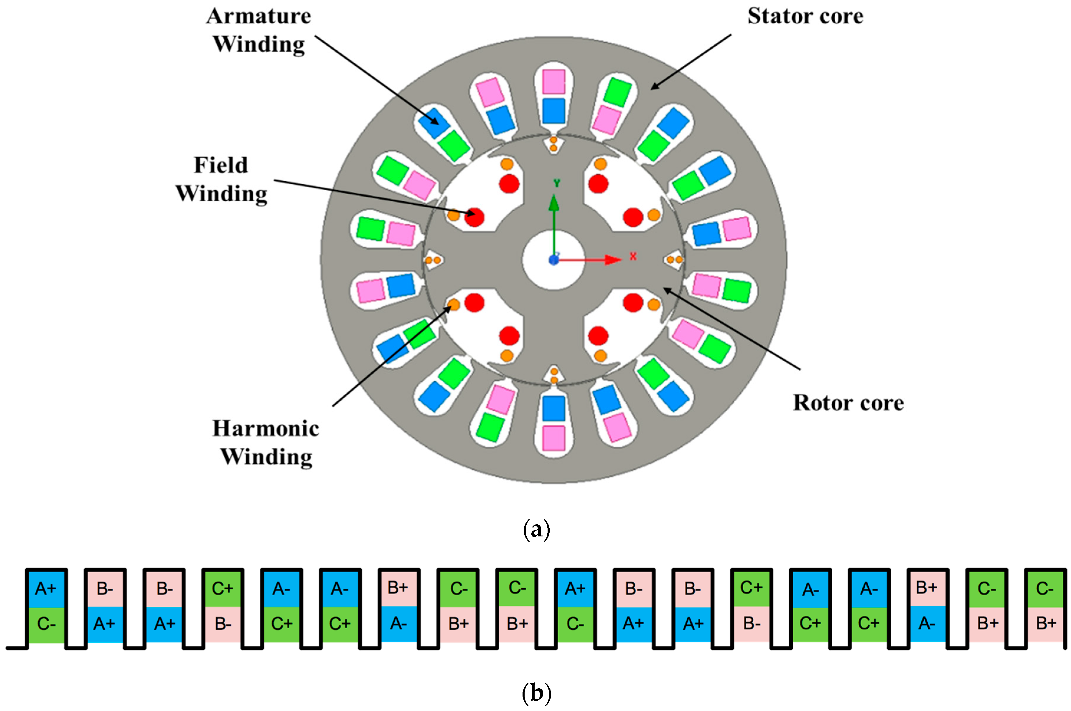
2. Proposed Topology and Working Principle

In the following, we discuss the operation and working principle of the proposed brushless technique for WRSMs based on an open winding pattern and dual-inverter control.

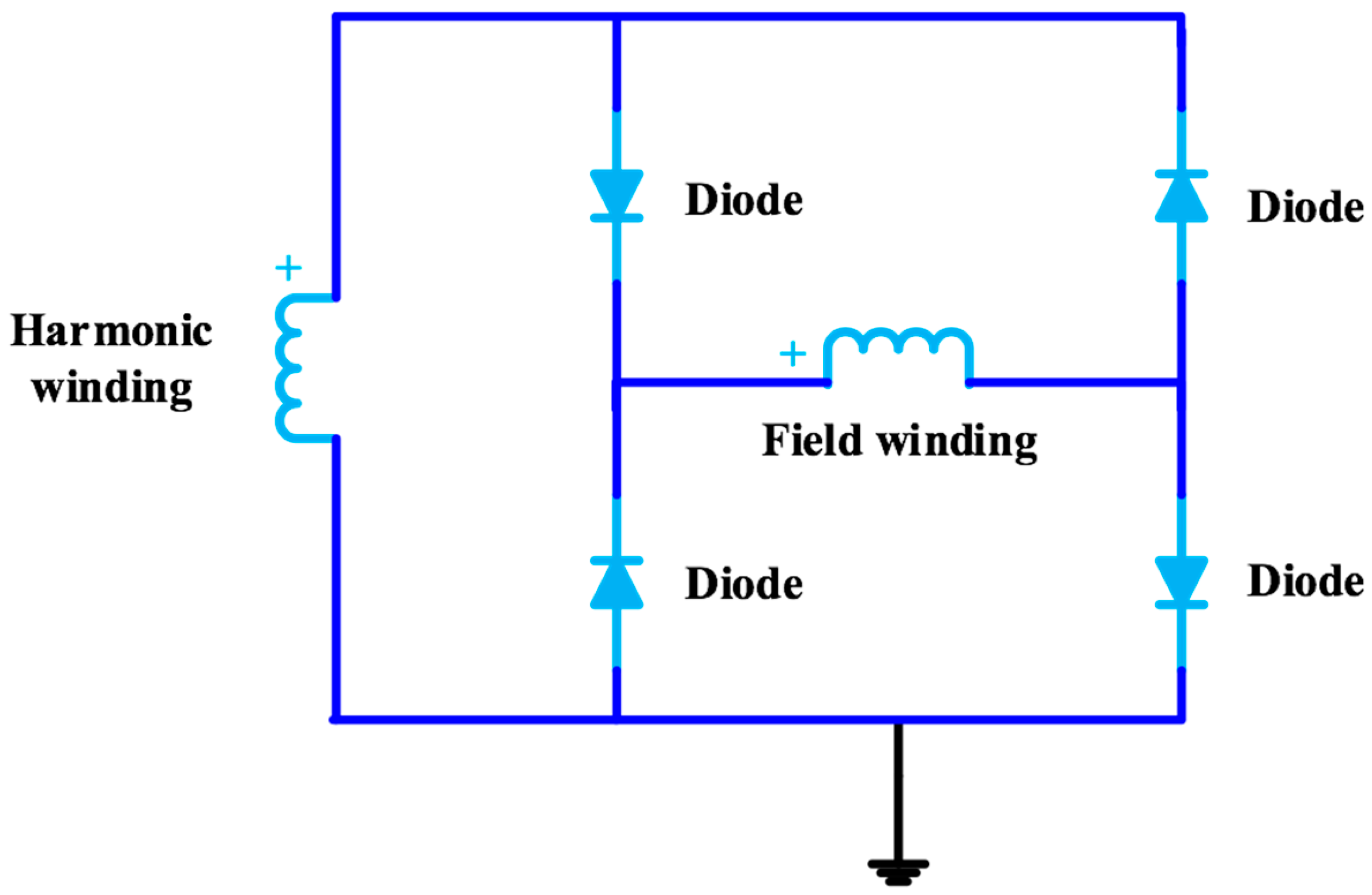
2.1. Proposed Topology

The simplified arrangement of the machine topology is shown in Figure 1. The proposed topology is comprised of two inverters connected to the terminals of the armature winding. These inverters operate according to the given reference currents. The reference current signals for inverter-1 and inverter-2 are generated by Equations (1) and (2), respectively.
I a 1 r e f = { sin ( ω t ) 0 < ω t < 2 π 0 o t h e r w i s e I b 1 r e f = { sin ( ω t 2 π 3 ) 2 π 3 < ω t < 8 π 3 0 o t h e r w i s e I c 1 r e f = { sin ( ω t 4 π 3 ) 4 π 3 < ω t < 10 π 3 0 o t h e r w i s e
I a 2 r e f = { sin ( ω t ) 2 π < ω t < 4 π 0 o t h e r w i s e I b 2 r e f = { sin ( ω t 2 π 3 ) 0 < ω t < 2 π 3   a n d   8 π 3 < ω t < 4 π 0 o t h e r w i s e I c 2 r e f = { sin ( ω t 4 π 3 ) 0 < ω t < 5 π 3   a n d   10 π 3 < ω t < 4 π 0 o t h e r w i s e
These equations are formulated such that both inverters will be phase-shifted 180° and provide an output current for alternative cycles. Unlike existing brushless techniques, both inverters deliver the same magnitude of three-phase current at the same frequency. The composite output of both inverters results in a three-phase armature current that is non-sinusoidal and inherently contains a third-harmonic current component in addition to the fundamental. This third-harmonic current component is used to induce currents in the specially designed 12-pole rotor harmonic winding, which is connected to the rotor field winding through a rotating full-bridge rectifier. The induced currents are rectified to supply DC current to the rotor field winding to produce a rotor field. This field produces a torque when it interacts with the main field. To validate the operation and analyze the electromagnetic performance of the proposed dual-inverter-controlled brushless operation of the WRSM, a 4-pole, 18-slot machine was used. The investigated machine structure and its winding pattern are shown in Figure 2 [2].

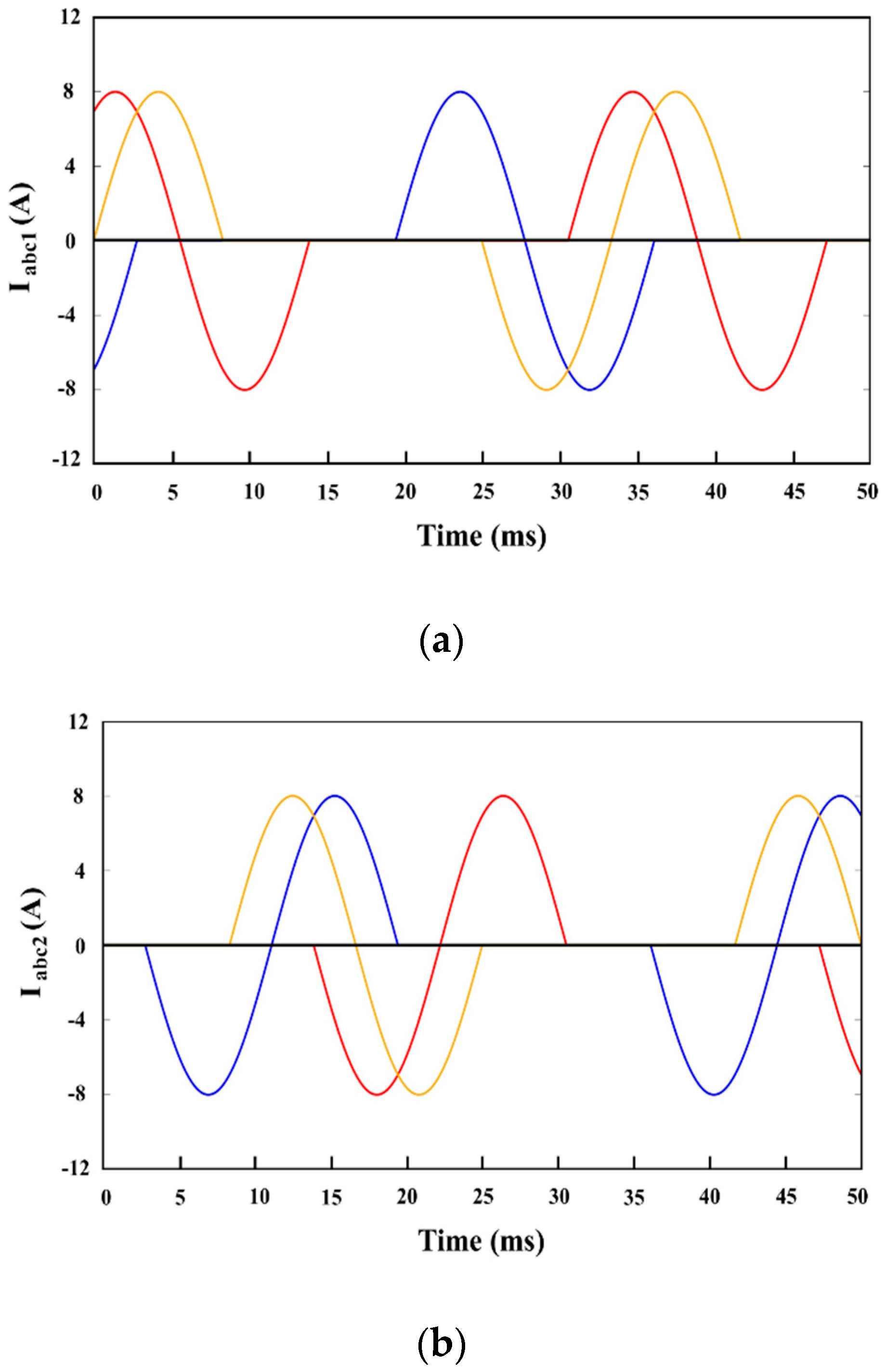
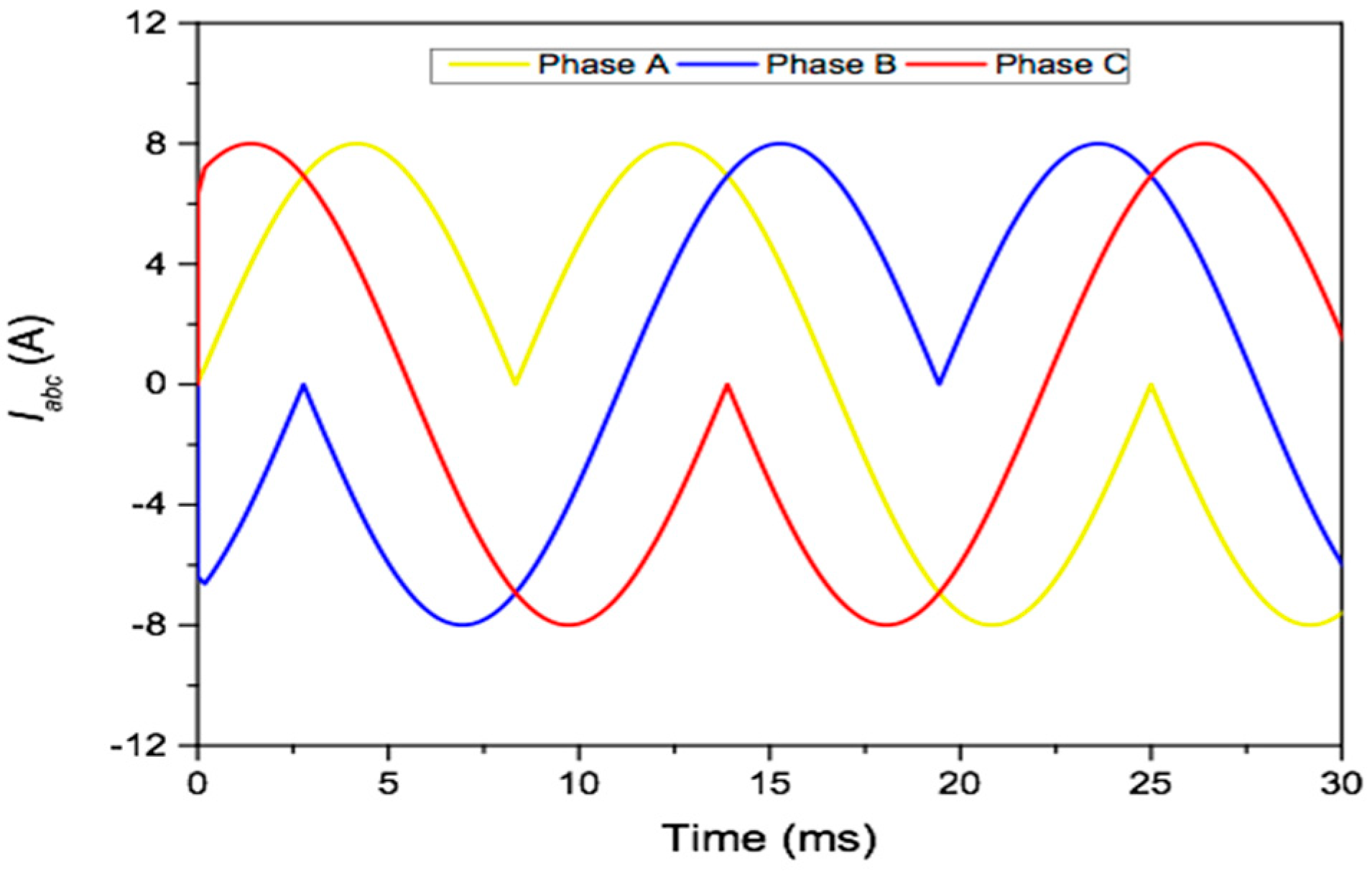
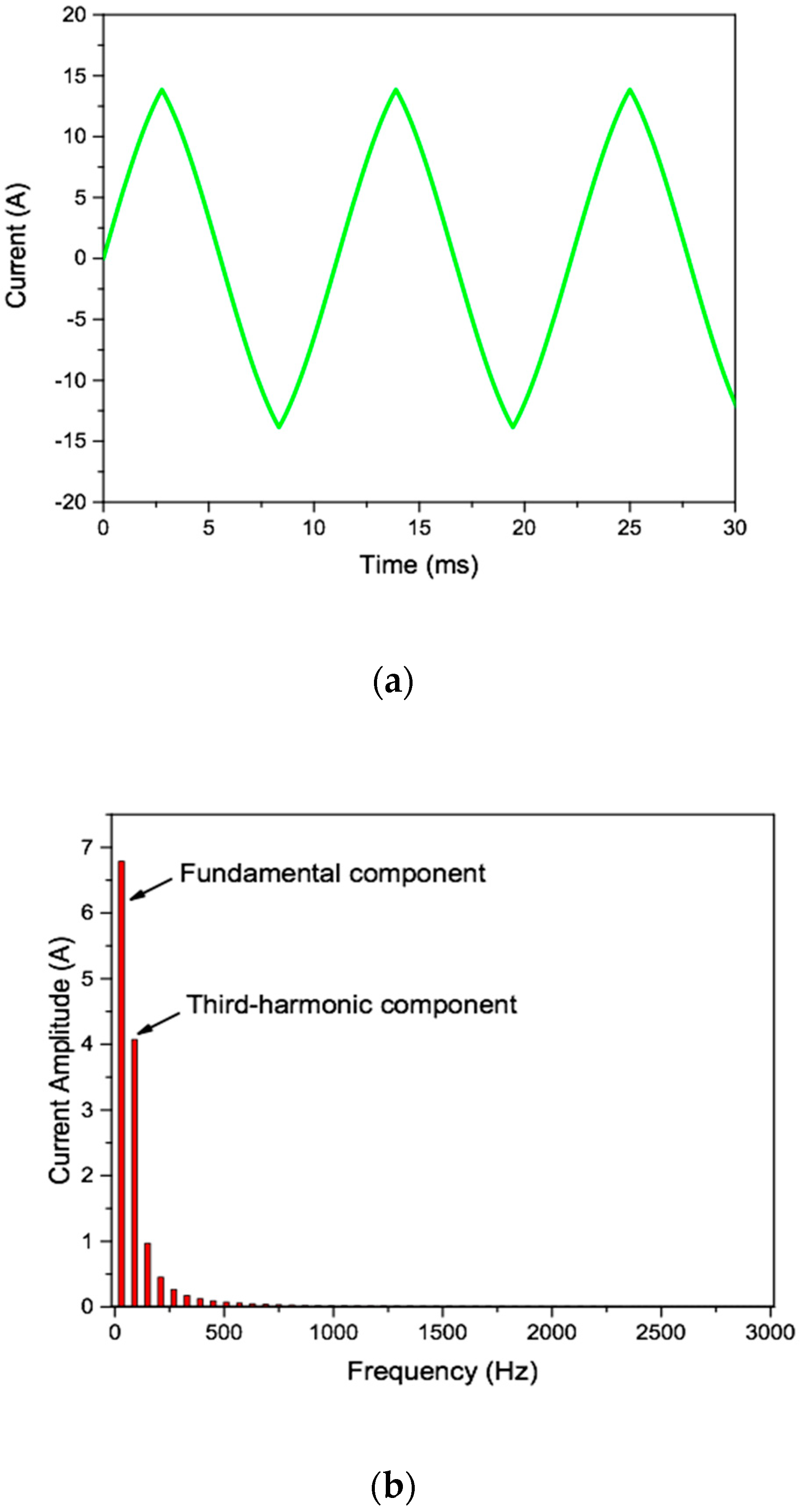
2.2. Working Principle

To achieve brushless operation for WRSMs using an open-winding pattern, two current-controlled inverters were used. These inverters used a simple and classical current control algorithm that was executed in the synchronous frame of reference in order to avoid the complexities associated with existing brushless techniques. The detailed implementation of the employed current control algorithm for inverter-1 and inverter-2 is shown in Figure 3a,b, respectively. The implemented control algorithm for both inverters was identical, but the reference current signals were adjusted using Equations (1) and (2), respectively, to achieve the required shape of three-phase input armature currents. In the implemented control strategy for inverter-1 and 2, the reference currents Iabc1-ref and Iabc2-ref were transformed from the abc frame of reference to dq0. The same currents were used for the transformation from the abc to the αβ frame and for the current angle calculation. The transformed reference currents were then compared with the feedback current signals Iabc1 and Iabc2. However, before comparison, these signals were also transformed from the abc to the dq0 frame. The comparison of signals generated error signals Edq1 and Edq2, which were then forwarded to the current controllers. The current controllers matched the reference and feedback current signals as closely as possible. The controlled output signals were transformed back from the dq0 to the abc frame of reference, and were then used for pulse width modulation (PWM) for the required commutation of the inverters’ switches [23].
The output currents for inverter-1 and 2 are shown in Figure 4a,b, respectively, and Figure 5 shows the composite shape of the input armature currents. The sum of the three-phase armature currents is illustrated in Figure 6a. This figure shows that the sum of three-phase currents in such a shape results in the third-harmonic waveform. To investigate the harmonic contents of the armature current (Iabc), fast Fourier transform (FFT) analysis was performed. The FFT plot is shown in Figure 6b, illustrating the fundamental and third-harmonic current components of the armature current of phase A. A 12-pole third-harmonic component induces a current in the rotor harmonic winding, which is used for the field excitation of the machine by a rectifier.
If the higher harmonic currents are neglected and only the fundamental and third-harmonic current components are considered, the composite three-phase currents are given by:
I a = I ( sin ω t + n sin 3 ω t )
I b = I [ sin ( ω t 2 π 3 ) + n sin 3 ( ω t 2 π 3 ) ]
I c = I [ sin ( ω t + 2 π 3 ) + n sin 3 ( ω t + 2 π 3 ) ]
where n is the weightage per unit third-harmonic component. The resultant MMF from the above three-phase armature currents is
F a = I a N ϕ [ sin θ e ]
F b = I b N ϕ [ sin ( θ e 2 π 3 ) ]
F c = I c N ϕ [ sin ( θ e + 2 π 3 ) ]
where
N ϕ = 4 π N 2
Here N is the winding turns per phase, θe = ωt + θo, θe is the electrical angle, and θo is rotor initial position.
The overall MMF produced by the three-phase armature currents can be expressed as
F a b c ( θ e , i a b c ) = 3 2 I 1 N ϕ cos ( ω t θ e ) + I 3 N ϕ cos 3 ( ω t + θ e )
where I1 is the amplitude of the fundamental current and I3 is the third-harmonic current component.
In the above equation, it can be seen that the overall MMF is composed of two components: the fundamental and the time-pulsating third-harmonic. The fundamental component is used for generating the main field, and the third-harmonic component is used to induce back-EMFs in the harmonic winding of the rotor as shown below:
λ h = N h N ϕ { 3 2 I 1 cos ( ω t θ e ) + n I 3 cos ( 3 ω t + 3 θ e ) } R g
where Nh is the number of rotor harmonic turns and Rg is the air gap reluctance.
The induced back-EMFs in the rotor harmonic winding are given by Equation (7), where during one electrical rotation, six-harmonic coils are available.
e m f h = 6 d λ h d t = 18 N h N ϕ I 3 ω sin 3 ( 2 ω t + θ 0 ) R g
The induced harmonic back-EMF is rectified and supplied to the rotor main field winding, which further interacts with the main field to generate a torque.

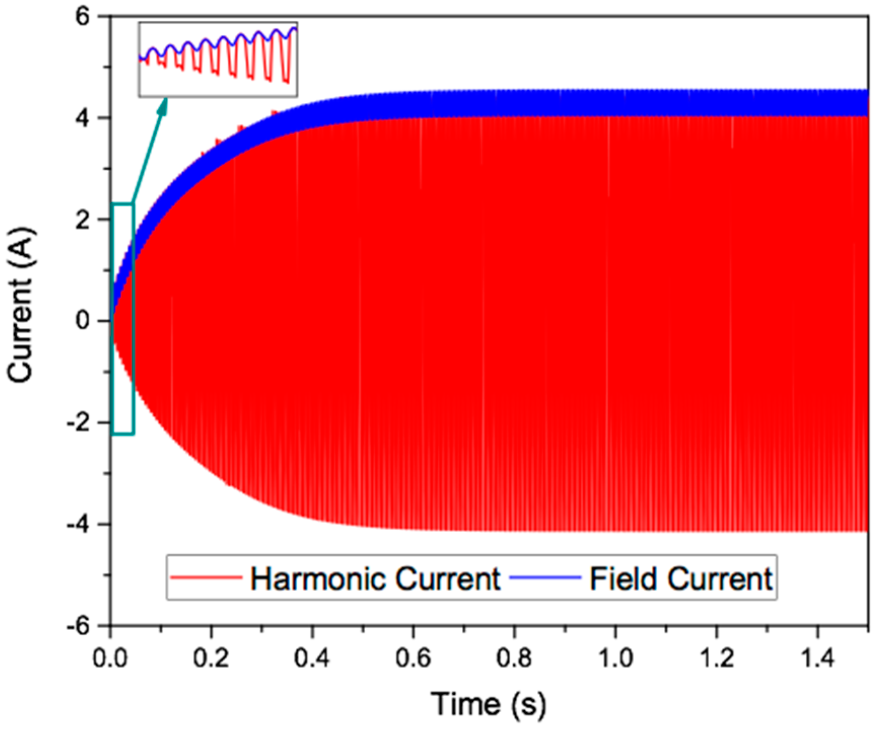
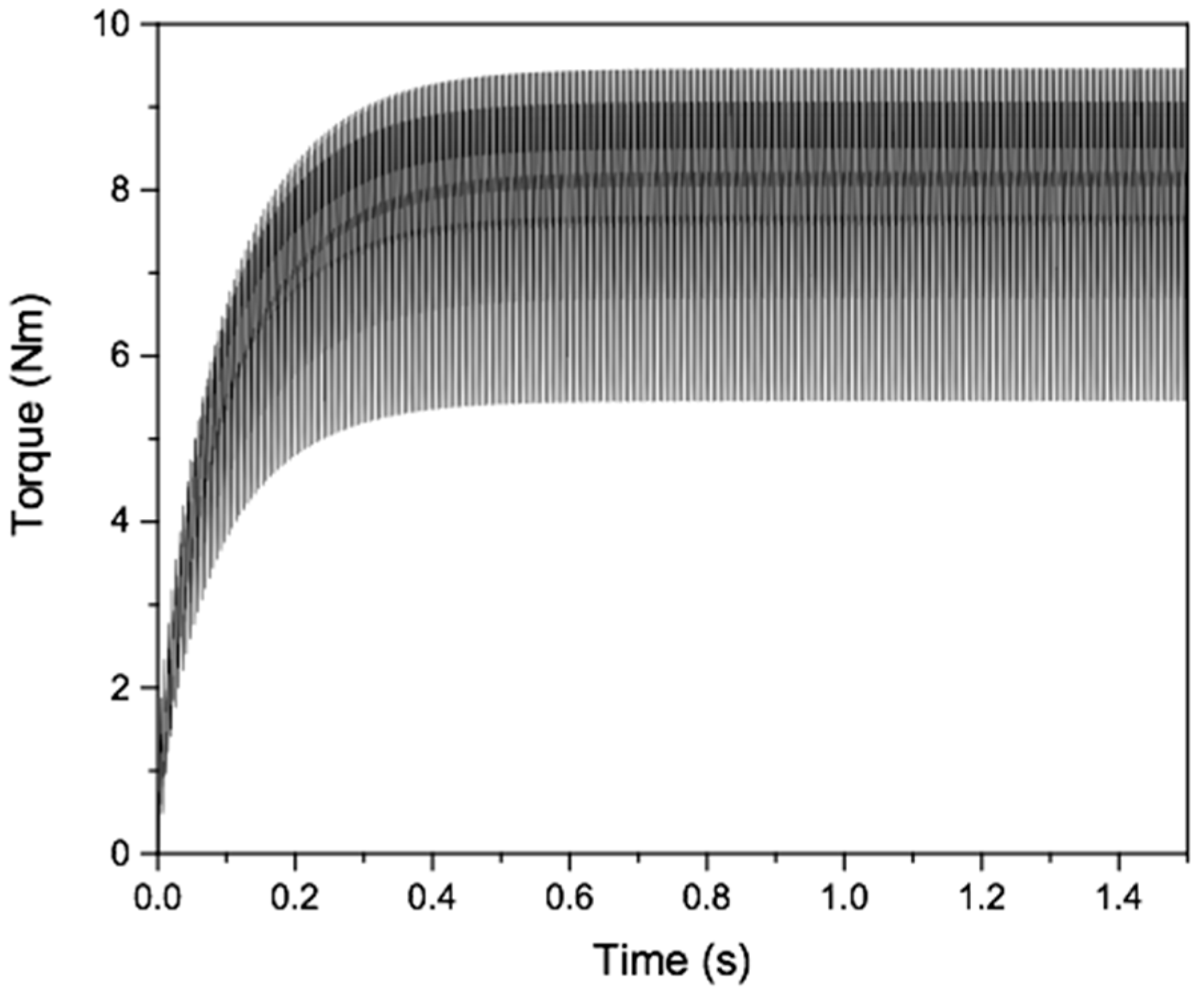
3. Finite Element Analysis

The finite element method was used to carry out a finite element analysis (FEA) to validate the operation and electromagnetic performance of the proposed brushless technique. The machine structure was adopted from [22] and its parameters are listed in Table 1 along with the parameters of conventional brushed WRSMs.
The armature winding of the investigated machine was provided with currents of 8 A (peak). The armature current generated by the two inverters was non-sinusoidal and comprised of fundamental and third-harmonic current components. For brushless operation, the rotor was modified to contain an additional winding, called harmonic winding. As shown in Figure 7, the harmonic and field windings were connected through a diode rectifier in ANSYS Maxwell 2-D simulation. Therefore, no input current was given to the field winding. Because the number of poles of harmonic winding was different than that of the field winding, it induced voltage by intercepting air gap flux. This voltage caused a current to flow in the rotor circuit. The simulation was performed for 1.5 s, and a steady-state field current and output torque were achieved. The magnetic field density plots of the investigated machine for simulations of 0.015 s and 1.5 s are shown in Figure 8a,b, respectively. These plots show that the operating flux density of the machine was under the saturation range. The three-phase flux linkages are presented in Figure 9.
The rotor field and harmonic currents are shown in Figure 10 and the output torque of the machine is illustrated in Figure 11. The average torque is given for one cycle under the steady-state condition. As seen from the results, while there was no field current, the rotor circuit initially had no current and the torque was zero. However, as the rotor rotated and intercepted the air gap harmonic flux, voltage was induced in the harmonic winding, which eventually started to increase current in the harmonic and field windings, and the torque was generated accordingly. The current and torque instantaneous values were proportional, as shown in Figure 10 and Figure 11. The average torque was 7.31 Nm.
The torque ripple of the investigated machine was about 50.62%. This torque ripple could either be minimized by adopting an optimization algorithm or by skewing the armature winding arrangement of the machine.

4. Conclusions

A dual-inverter-controlled brushless technique for WRSMs based on an open-winding pattern was proposed in this paper. The technique used two customary inverters connected to the two terminals of the armature winding. The inverters were operated using the given current reference signals to obtain a unique current shape for the armature winding. The generated composite armature current comprised fundamental and third-harmonic current components. The generated third-harmonic component with 12 poles was induced into the 12-pole rotor harmonic winding. This current was then rectified for the excitation of the rotor field using a rotating rectifier. Finally, FEA was performed to validate the proposed brushless technique and obtain the output torque.
In contrast to the existing techniques, the proposed brushless topology does not require the injection of two different magnitudes of current, any additional switches installed between the inverter and the armature winding, sophisticated inverter topology and drive systems, or modifications in machine structure. This makes the proposed brushless topology more advantageous when compared to the conventional brushless WRSM topologies.

Author Contributions

Conceptualization, S.S.H.B., G.J.S.; Funding acquisition, J.-S.R.; Investigation, S.S.H.B., G.J.S. and F.A.C.; Writing—review & editing, G.J.S. and S.S.H.B. All authors have read and agreed to the published version of the manuscript.

Funding

This research was supported in part by the National Research Foundation of Korea funded by the Ministry of Education (2016R1D1A1B01008058), Human Resources Development (No.20184030202070) of the Korea Institute of Energy Technology Evaluation and Planning (KETEP) grant funded by the Korea government Ministry of Trade, Industry and Energy, and by the Korea Research Fellowship Program through the National Research Foundation (NRF) of Korea funded by the Ministry of Science and ICT (2019H1D3A1A01102988).

Conflicts of Interest

The authors declare no conflict of interest.

References

  1. Sun, L.; Gao, X.; Yao, F.; An, Q.; Lipo, T. A new type of harmonic current excited brushless synchronous machine based on an open winding pattern. In Proceedings of the 2014 IEEE Energy Conversion Congress and Exposition (ECCE), Pittsburgh, PA, USA, 14–18 September 2014; pp. 2366–2373. [Google Scholar]
  2. Yao, F.; Sun, D.; Sun, L.; Lipo, T.A. Dual Third-Harmonic-Current Excitation Principle of a Brushless Synchronous Machine Based on Double Three-Phase Armature Windings. In Proceedings of the 2019 22nd International Conference on Electrical Machines and Systems (ICEMS), Harbin, China, 11–14 August 2019; pp. 1–4. [Google Scholar]
  3. Di Gioia, A.; Brown, I.P.; Nie, Y.; Knippel, R.; Ludois, D.C.; Dai, J.; Hagen, S.; Alteheld, C. Design and Demonstration of a Wound Field Synchronous Machine for Electric Vehicle Traction with Brushless Capacitive Field Excitation. IEEE Trans. Ind. Appl. 2018, 54, 1390–1403. [Google Scholar] [CrossRef]
  4. Kano, Y. Design optimization of brushless synchronous machines with wound-field excitation for hybrid electric vehicles. In Proceedings of the 2015 IEEE Energy Conversion Congress and Exposition (ECCE), Montreal, QC, Canada, 20–24 September 2015; pp. 2769–2775. [Google Scholar]
  5. Stancu, C.; Ward, T.; Rahman, K.M.; Dawsey, R.; Savagian, P. Separately Excited Synchronous Motor with Rotary Transformer for Hybrid Vehicle Application. In Proceedings of the 2014 IEEE Energy Conversion Congress and Exposition (ECCE), Pittsburgh, PA, USA, 14–18 September 2014; pp. 1754–1761. [Google Scholar]
  6. Ruuskanen, V.; Niemel, M.; Pyrhonen, J.; Kanerva, S.; Kaukonen, J. Kaukonen, Modelling the brushless excitation system for a synchronous machine. IET Electr. Power Appl. 2009, 3, 231–239. [Google Scholar] [CrossRef]
  7. Zhu, X.Y.; Cheng, M.; Zhao, W.X.; Zhang, J.Z.; Hua, W. An Overview of Hybrid Excited Electric Machine Capable of Field Control. Trans. China Electrotech. Soc. 2008, 23, 30–39. [Google Scholar]
  8. Ayub, M.; Hussain, A.; Jawad, G.; Kwon, B. Brushless Operation of a Wound-Field Synchronous Machine Using a Novel Winding Scheme. IEEE Trans. Magn. 2019, 55, 1–4. [Google Scholar] [CrossRef]
  9. Khan, S.; Bukhari, S.S.H.; Ro, J. Design and Analysis of a 4-kW Two-Stack Coreless Axial Flux Permanent Magnet Synchronous Machine for Low-Speed Applications. IEEE Access 2019, 7, 173848–173854. [Google Scholar] [CrossRef]
  10. Yao, F.; An, Q.; Sun, L.; Lipo, T.A. Performance Investigation of a Brushless Synchronous Machine with Additional Harmonic Field Windings. IEEE Trans. Ind. Electron. 2016, 63, 6756–6766. [Google Scholar] [CrossRef]
  11. Inoue, K.; Yamashita, H.; Nakamae, E.; Fujikawa, T. A brushless self-exciting three-phase synchronous generator utilizing the 5th-space harmonic component of magneto motive force through armature currents. IEEE Trans. Energy Convers. 1992, 7, 517–524. [Google Scholar] [CrossRef]
  12. Yao, F.; An, Q.; Sun, L.; Illindala, M.S.; Lipo, T.A. Optimization design of stator harmonic windings in brushless synchronous machine excited with double-harmonic-windings. In Proceedings of the International Energy and Sustainability Conference (IESC), Farmingdale, NY, USA, 19–20 October 2017; pp. 1–6. [Google Scholar]
  13. Ayub, M.; Bukhari, S.S.H.; Jawad, G.; Kwon, B.-I. Reluctance Torque Utilization to Improve the Starting and Average Torques of a Brushless Wound Field Synchronous Machine. In Proceedings of the 19th International Symposium on Applied Electromagnetics and Mechanics (ISEM 2019), Nanjing, China, 15–18 September 2019. [Google Scholar]
  14. An, Q.; Gao, X.; Yao, F.; Sun, L.; Lipo, T. The structure optimization of novel harmonic current excited brushless synchronous machines based on open winding pattern. In Proceedings of the 2014 IEEE Energy Conversion Congress and Exposition (ECCE), Pittsburgh, PA, USA, 14–18 September 2014; pp. 1754–1761. [Google Scholar]
  15. Ayub, M.; Bukhari, S.S.H.; Jawad, G.; Kwon, B.-I. Brushless wound field synchronous machine with third-harmonic field excitation using a single inverter. Electr. Eng. 2019, 101, 165–173. [Google Scholar] [CrossRef]
  16. Ali, Q.; Lipo, T.A.; Kwon, B.-I. Design and analysis of a novel brushless wound rotor synchronous machine. IEEE Trans. Magn. 2015, 51, 1. [Google Scholar] [CrossRef]
  17. Ayub, M.; Atiq, S.; Sirewal, G.J.; Kwon, B. Fault-Tolerant Operation of Wound Field Synchronous Machine Using Coil Switching. IEEE Access 2019, 7, 67130–67138. [Google Scholar] [CrossRef]
  18. Ayub, M.; Jawad, G.; Kwon, B. Consequent-Pole Hybrid Excitation Brushless Wound Field Synchronous Machine with Fractional Slot Concentrated Winding. IEEE Trans. Magn. 2019, 55, 1–5. [Google Scholar] [CrossRef]
  19. Jawad, G.; Ali, Q.; Lipo, T.A.; Kwon, B.I. Novel brushless wound rotor synchronous machine with zero-sequence third-harmonic field excitation. IEEE Trans. Magn. 2016, 52, 1–4. [Google Scholar] [CrossRef]
  20. Ali, Q.; Bukhari, S.S.H.; Atiq, S. Variable-speed, sub-harmonically excited BL-WRSM avoiding unbalanced radial force. Electr. Eng. 2019, 101, 251–257. [Google Scholar] [CrossRef]
  21. Ayub, M.; Sirewal, G.J.; Bukhari, S.S.H.; Kwon, B.-I. Brushless wound rotor synchronous machine with third-harmonic field excitation. Electr. Eng. 2019, 102, 259–265. [Google Scholar] [CrossRef]
  22. Yao, F.; An, Q.; Gao, X.; Sun, L.; Lipo, T.A. Principle of operation and performance of a synchronous machine employing a new harmonic excitation scheme. IEEE Trans. Ind. Appl. 2015, 51, 3890–3898. [Google Scholar] [CrossRef]
  23. Li, Z.; Zang, C.; Zeng, P.; Yu, H.; Li, S.; Bian, J. Control of a Grid-Forming Inverter Based on Sliding-Mode and Mixed H2/H Control. IEEE Trans. Ind. Appl. 2017, 64, 3862–3872. [Google Scholar]
Figure 1. Machine topology.
Energies 13 02205 g001
Figure 2. (a) Machine structure; (b) winding configurations.
Energies 13 02205 g002
Figure 3. Complete diagram for (a) inverter-1, and (b) inverter-2. PWM: pulse width modulation.
Energies 13 02205 g003
Figure 4. Output three-phase current of (a) inverter-1 and (b) inverter-2.
Energies 13 02205 g004
Figure 5. Three-phase armature currents (Iabc).
Energies 13 02205 g005
Figure 6. (a) Sum of three-phase currents, and (b) the fast Fourier transform (FFT) plot of phase A current.
Energies 13 02205 g006
Figure 7. Rotor circuit showing the connection of harmonic and field windings.
Energies 13 02205 g007
Figure 8. Magnetic flux density distribution plot of the machine at (a) 0.015 s and (b) 1.5 s.
Energies 13 02205 g008
Figure 9. Three-phase flux linkages for the proposed brushless WRSM.
Energies 13 02205 g009
Figure 10. Rotor currents for the proposed brushless WRSM.
Energies 13 02205 g010
Figure 11. Output torque of the proposed brushless WRSM.
Energies 13 02205 g011
Table 1. Machine parameters. WRSM: wound rotor synchronous machine.
ParameterConventional Brushed WRSMProposed Brushless WRSM
Machine poles/stator slots4/184/18
Stator outer diameter130 mm130 mm
Rotor outer diameter79 mm79 mm
Stack length120 mm120 mm
Field winding no. of turns140140
Harmonic winding no. of turns-14
Armature winding no. of turns250250
Power700 W690 W
Voltage58 V56.5 V
Efficiency93%91%
Core loss3540 W

