Abstract
In this paper, a single-phase five-level rectifier with coupled inductors is studied. First, a discrete mathematical model of a single-phase five-level rectifier is created in two-phase(αβ). A traditional single vector finite control set model predictive control (FCS-MPC) algorithm is improved to overcome the problems of a varying switching frequency, the large amount of time needed for calculation, and the inaccurate setpoint of current loop tracking. Then, the objective function of the system is established, and a simple objective function is used instead of an iterative optimization of the traditional FCS-MPC algorithm. At the same time, to eliminate the delay error and to reduce harmonic distortion, deadbeat control technology is introduced. Finally, the simulation and experimental results show that the improved model predictive current control algorithm not only retains the fast response of traditional model predictive control, but also has the advantages of fixed switching frequency, small calculation time, and small current steady-state error.
1. Introduction
With the rapid development of power electronics technology, single-phase pulse width modulation (PWM) converters have become more common. They have the advantages of a high-power on the grid-side, low harmonic distortion, and bidirectional energy flow [1]. Multilevel rectifiers show great advantages in reducing the size of passive components and reducing switching voltage stress. In addition, multilevel rectifiers have even more advantages in high voltage and high-power scenarios. Currently, multilevel rectifiers have been widely used in high voltage direct current (HVDC) transmission systems, power electronics transformers (PET), and electric locomotive traction. A single-phase five-level rectifier using coupled inductors has been proposed in reference [2]. Compared with traditional five-level rectifiers, it has fewer switching devices, no clamping diodes, low cost, and small size. Because there is only one supporting capacitor on the DC side, there is no problem with voltage balance on the capacitors.
Model predictive control (MPC) technology is an advanced control method. In the 1960s, MPC technology was proposed. It has the advantages of intuitive concepts, fast dynamic performance, and strong robustness [3]. It is suitable for many different types of systems, however, due to the limitations of microprocessor technology, it was not until 1980 that MPC technology was applied to high-power systems with low switching frequencies. In recent years, with the development of microprocessor technology, the application of MPC technology has become more and more widespread [4,5,6]. For instance, the traditional FCS-MPC algorithm first uses an online method to calculate all the voltage vectors, and then selects the voltage vector that minimizes the error of the objective function for the next cycle. A single vector model predictive control algorithm has been introduced in [7]. Because only one voltage vector is used in one cycle, a high system sampling frequency and data processing speed are required to achieve accurate control. Therefore, higher requirements are placed on the microprocessor. Simultaneously, the switching frequency is not fixed, and the current harmonics are widely distributed which causes some difficulties in the design of the filter. Documents [8,9] proposed improvements to the FCS-MPC pulse mode or vector sequence to improve the control accuracy. Reference [10] proposed a method that uses a combination of MPC with optimized pulse patterns which satisfies the strict steady-state as well as the dynamic performance requirements. The authors in [11] presented a dead-beat predictive direct power control (DPC) strategy and its improved voltage-vector sequences for a reversible three-phase grid-connected voltage-source converters. This new algorithm is based on virtual-flux (VF) estimation and operates with constant switching frequency [12]. References [13,14] applied space vector modulation technology (SVM) that is combined with MPC control to a six-phase inverter. This method calculates the duty cycle and determines the best vector at the current time with minimum error. To improve the performance of the voltage source inverter, the MPC using continuous variables. It used the output of the controller as the reference voltage to be generated by a PWM modulator [15]. In [16], the MPC algorithm uses the heuristic method in order to reduce the calculation effort. In [17,18,19] a method is presented which increases the prediction horizon of FCS-MPC so as to control the performance. The main drawback is that the increased numbers of possible converter states requires the control hardware to increase the computation time. A deadbeat model predictive control (DBC) was created, which effectively eliminated the errors caused by system calculation and sampling delay [20]. References [21,22] proposed a control method based on the two-vector optimal duty cycle and added deadbeat control technology, which effectively fixed the switching frequency and reduced the harmonic distortion rate of the grid-side current. However, the need for a large amount of calculation is still present.
This paper studies a single-phase five-level rectifier with coupled inductors. To improve the overall performance of this rectifier, fix the switching frequency, reduce a large number of calculations in the online optimization process of the traditional single vector FCS-MPC algorithm, and retain the fast response characteristics of the traditional FCS-MPC, the traditional model predictive control algorithm is improved. First, a discrete mathematical model of a single-phase five-level PWM rectifier in two-phase is established, and the objective function of the system is derived based on the traditional FCS-MPC algorithm. Then, to eliminate the delay error of systematic sampling and calculation, deadbeat control technology is introduced. To obtain the modulation function expected by the system, an improved model predictive current control (MPCC) algorithm is combined with space vector modulation technology to simplify and solve the objective function. The modulation module produces the drive signals of the rectifiers according to the modulation function. Finally, some simulation and experimental results are shown for the system. Although the proposed algorithm adds deadbeat control technology and space vector technology, this method greatly simplifies the modulation function of the rectifier. It achieves the purposes of precise control, small calculation amount, and fixed switching frequency. The improved MPCC algorithm is compared with a traditional single-vector FCS-MPC algorithm and proportional integral (PI) current decoupling control.
2. Mathematical Model of Single-Phase Five-Level PWM Rectifier
2.1. Discrete Model of Single-Phase Five-Level PWM Rectifier
The single-phase five-level PWM rectifier topology based on coupled inductors is shown in Figure 1. In that figure, is grid-side voltage, is grid-side current, is the rectifier input voltage, L is the equivalent series inductance of line filter (its internal resistance is ignored), – are insulated gate bipolar transistors (IGBT), and are the coupled inductors in series, C is the symbols for the capacitors in the DC-link, is a resistive load of DC-link, and is the voltage of DC-link.
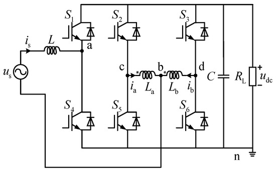
Figure 1.
Single-phase five-level rectifier topology based on coupled inductor.
According to Figure 1, the coupled inductors are described as
where M is coupling value and is value of leakage inductance.
The grid-side current can be expressed as
where and are the currents flowing through and .
The voltage drop between coupled inductors depends on different operating modes of the rectifier.
In Equation (3), , , and are the pressure drops between points of b, c, and d to location n. Under the assumption of Equation (3), it is possible to calculate the pressure drop between points of b to n as:
Ignoring the effect of on the coupled inductors, the grid input voltage is given by:
The ideal binary logic switching function is defined as:
where is the switch state of the ith bridge arm.
Among them, the switch function S has five values: −1, −1/2, 0, 1/2, and 1.
Applying Kirchhoff’s law and integrating the above formula to obtain the dynamic equation of the rectifier produces.
where
The grid-side voltage and current obtained by the single-phase system are scalars and therefore cannot form the voltage and current vectors that accurately control the system. Therefore, it is necessary to obtain a grid-side voltage vector and a current vector by virtually generating a voltage and current value that lags behind and is superimposed on the actual value.
The building of grid-side voltage and current of single-phase five-level PWM rectifier in αβ two-phase stationary coordinate system using an orthogonal method is:
where (, ) and (, ) are the components of the grid-side voltage and grid-side current on the αβ axis, (, ) are the peak values of the grid-side voltage and current, and φ is the angle of the current hysteresis voltage.
Simultaneously, Equations (7)–(12) can obtain the dynamic equation of single-phase five-level rectifier in αβ stationary coordinate system.
In order to facilitate the discretization process, Equation (13) is modified.
The next step is to discretize Equation (14) using Euler’s forward method. The result produces. Equation (15).
where (, ) are the αβ axis current values of the next moment of the predicted system, and is the PWM switching period of the system.
2.2. Single-Phase Five-Level Rectifier Space Voltage Vector
The single-phase five-level PWM rectifier topology based on coupled inductors has eight operating modes. Eight space voltage vectors correspond to eight operating states that are shown in Table 1. Side by side, each of the small vectors and the zero vector has a redundant vector.

Table 1.
Switch vector of single-phase five-level rectifier.
Figure 2 shows that according to the magnitude and direction of the vector, eight types of switching vectors can be divided into four sections, where Vref is the reference voltage vector.
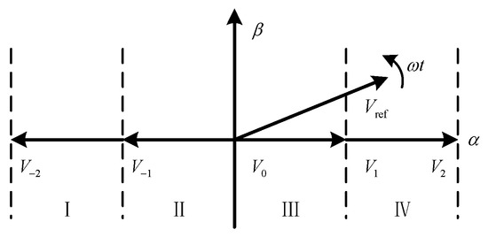
Figure 2.
Sector partition single-phase five-level rectifier.
3. Improved Model Predictive Current Control
The traditional single-vector FCS-MPC algorithm uses only one vector in one PWM switching cycle, which makes it impossible to accurately track the measured current at the end of the cycle. As a result, control accuracy is reduced. If one successively solves the objective function for multiple vectors in one PWM switching cycle, the control accuracy can be improved, but a large number of calculations will limit the increase of the switching frequency. Simultaneously, there are also problems such as unstable switching frequency, poor steady-state performance, and large current harmonic distortion.
To eliminate these problems, this paper improves the traditional FCS-MPC algorithm and proposes an MPCC algorithm based on modulation functions. The algorithm uses the principle of equal area to introduce modulation functions, combine space vector modulation technology with model predictive control technology, and obtain the optimal modulation function value corresponding to the extreme value by solving the objective function. The control of the system is completed through the modulation module. This algorithm needs a small amount of calculation and therefore has a fast-dynamic response. This speed increase enables the grid-side current to quickly and accurately track the target value. The two-phase stationary coordinate system can be used to complete the phase tracking of the system without a phase-locked loop, thereby reducing the complexity of the system.
3.1. Building the Objective Function
The objective function selects the optimum switching state. The traditional objective function has a different function and a variance function. Since this paper’s model has been created in a two-phase stationary coordinate system, the tracking of the target current can be completed in one cycle when the delay of the actual system is neglected. The objective function can be obtained as follows:
In Equation (16), (, ) and (, ) are the components of the grid-side current and the reference grid-side current on the αβ axis at the next moment, while λ is the weight coefficient. The objective function includes two forms of difference function and variance function.
As the calculation time of the difference function is short, it is advantageous to increase the PWM switching frequency. Considering that this algorithm needs to differentiate the objective function, and the difference function is not differentiable, it needs to be segmented. Therefore, the variance objective function, which is described in Equation (17) is used.
3.2. Introduce Modulation Function
To solve the problem that the traditional single-vector FCS-MPC algorithm uses only one vector and the switching frequency is not fixed in one PWM period, the area equivalent principle is used to introduce a modulation function. This method uses multiple switching vectors in one cycle to achieve accurate current tracking and reduce grid-side current harmonics.
The current change of a single-phase five-level PWM rectifier in a PWM switching period is shown in Figure 3. The sequence of each vector’s action is as follows:
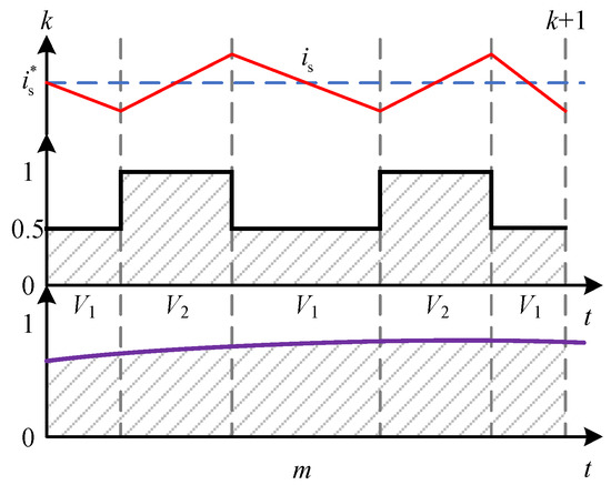
Figure 3.
Relationship between modulation function and switching states in positive half cycle.
The corresponding action time of each vector is:
where
In Equation (18), and are the action time with respect to and .
From the volt-second balance principle, one can obtain Equation (19), where m is the modulation function.
where m is a modulation function.
Including Equations (18) and (19) into Equation (15) and simplifying the expression, one obtains Equation (20), where and are the components of the modulation function m on the αβ axis.
3.3. Deadbeat Compensation Control
Ideally, the sampling, calculation, and output of the system should be completed at the same time. However, in practice, because hardware sampling and system calculation both require a certain amount of time, the calculation link of the system often lags behind the sampling link. This delay creates calculation errors and inaccurate current tracking. To eliminate this error, a beat system can be predicted in advance. That means that the current value at a time (k + 2) is used to complete the system control at time (k + 1). So, Equation (17) can be rewritten as:
As the objective function changes, the predicted current value at a time (k + 2) also varies. To remove the delay, the current at a time (k + 2) should be used in the cost function of Equation (8), instead of (k + 1):
3.4. Solving the Best Modulation Function
From Equation (20), we can know that the current value of the system at (k + 2) is closely related to the modulation function m. The function m determines the current value of the system at the moment. To minimize the prediction current error and the objective function variance, the modulation function m needs to be solved. The size of the modulation function m is determined by the values of both and . Therefore, the optimal modulation function m is an important part of the algorithm that minimizes the predicted current error and the variance of the objective function is solved.
Since the components of and on the β axis are 0, substituting Equations (19)–(22) into Equation (23) can eliminate the weight coefficient λ, and one can then obtain Equation (24).
The simultaneous use of Equations (19), (20) and (24) can produce the modulation function for the actual system in the next cycle. That function is shown in Equation (25).
3.5. Implementation of Improved MPCC Algorithm
Using this procedure, the control block diagram of the improved model predictive control algorithm is shown in Figure 4. The creation of the algorithm includes the following steps:
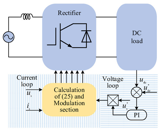
Figure 4.
Block diagram of improved model predictive control algorithm.
- (1)
- Sampling to obtain the grid-side voltage, current value and DC-side capacitor voltage value at the (k + 2) moment.
- (2)
- The DC-side voltage value is processed by the PI controller and the standardization grid-side voltage measurement operation is used to generate a reference current.
- (3)
- The modulation wave of the system is calculated through Equation (25), and the modulation wave is output to the subsequent modulation module. The modulation module distributes the corresponding PWM pulses to each power switch to complete the control of the system for one cycle.
4. Simulation Results
The single-vector FCS-MPC algorithm, PI current decoupling control, and improved MPCC algorithm were simulated using the MATLAB/Simulink platform. The three control methods use the parameters that are shown in Table 2.
Table 2.
Simulation system parameters.
Figure 5 shows the simulation steady-state waveforms of the grid-side current and the rectifier input voltage using the three different control methods. It can be observed that the grid-side voltage and current of the algorithms have the same phase. All of them achieve the unity power factor operation. Figure 5a shows that the single-vector FCS-MPC has a high harmonic content on the grid-side due to the non-fixed switching frequency as only one switching vector can be applied in one cycle. At the same time, some steps of the rectifier input voltage are lost, so that the total area of the input voltage is smaller than the total area of the reference voltage. Figure 5b,c show that an improved model predictive control algorithm can achieve the effect of PI current decoupling control under steady-state conditions.
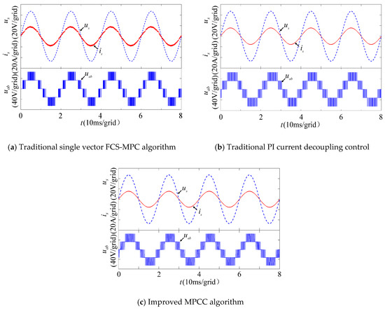
Figure 5.
Simulated waveforms of grid-side voltage and current and input voltage in steady state.
Figure 6 shows the simulation results of a Fast Fourier Transform (FFT) analysis of the grid-side currents for the three methods. Among them, the single-vector FCS-MPC high-order harmonics are widely distributed, and the total harmonic distortion (THD) is large, 8.83%. The PI current decoupling control and improved model predict that the total harmonic distortion of current control is low, 3.37% and 1.77%. In addition, the higher harmonics are distributed near the double PWM switching frequency, which is a value that is easy to filte.
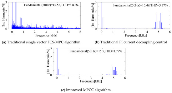
Figure 6.
Total harmonic distortion (THD) analysis of grid-side current simulation data.
5. Experimental Results
To further verify the correctness of the algorithm, this paper attempted to verify it via an actual experiment. The main circuit is a 1 kW low-power experimental platform. The controller uses a MicroLab from dSPACE. The grid-side voltage, current, and DC-side voltage were collected using a Bing zi three phase synchronous power transformer and a Hall sensor with model number VSM025A. The experimental arrangement is shown in Figure 7. In this experiment, the main circuit parameters are consistent with the simulation. The measured values are shown in Table 2.
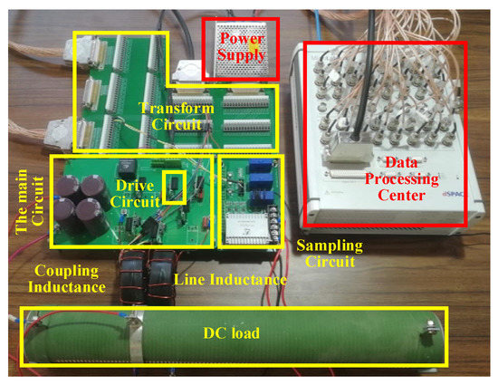
Figure 7.
Experiment Platform.
Figure 8 shows the waveforms of the grid-side voltage, grid-side current, and rectifier input voltage during the steady-state operation of the system. The results are consistent with the simulation. Figure 8a,b show that the traditional single vector FCS-MPC and the PI current decoupling control has a phase difference due to the sampling and calculation delay errors. The improved model predictive control has almost no phase difference when the deadbeat compensation is added. It is shown from Figure 8a,c that the improved MPCC algorithm fixes the switching frequency. The reason for the improvement is that the improved MPCC algorithm outputs the analog reference voltage of the rectifier.
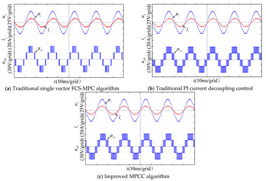
Figure 8.
Voltage and current on the grid-side and input voltage waveform in steady state.
In Figure 9, there are experiment results for a fast Fourier transform (FFT) analysis of the grid-side currents for the three methods. Figure 9c shows that the THD of the improved MPCC algorithm is 2.43%, and the THD of the traditional PI current decoupling control and the traditional single vector FCS-MPC algorithm are 4.37% and 9.22%. The improved model predictive control algorithm adds deadbeat control, which reduces the steady-state error of the control algorithm. The modulation function simplifies the control algorithm. As a result, the processor can complete the data processing in a shorter time. Therefore, the improved model predictive control algorithm has lower harmonics. These results are similar to what was found in the simulation. The THD of the improved MPCC algorithm is about half of the traditional PI current decoupling control. In addition, the third harmonic is slightly smaller, the current ripple is significantly reduced, and the stability is higher.
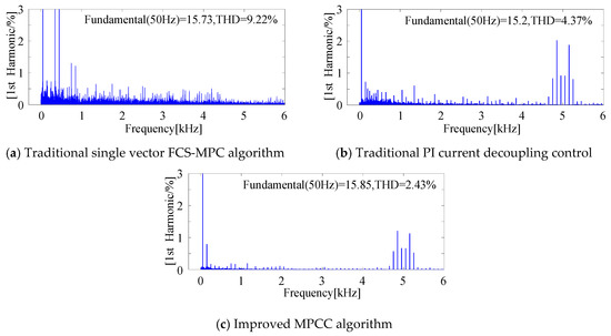
Figure 9.
THD analysis of grid-side current experiment data.
Figure 10 shows the waveforms of the DC-side voltage and the grid-side current when the DC-side load suddenly changes from 22 Ω to 11 Ω for each of the three control algorithms. The improved MPCC algorithm maintains the quickness of the traditional FCS-MPC algorithm. The current loop will affect the response speed of the voltage loop. Figure 10a,b shows that the voltage loop recovery speed is about 70 ms, while the traditional PI current decoupling control recovery time is 100 ms.
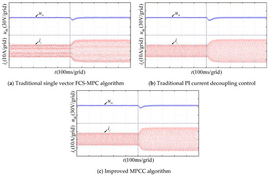
Figure 10.
Voltage and current on the grid-side and input voltage waveform in steady state.
Figure 11a,b shows the grid-side current experimental waveforms of the traditional PI current decoupling control and the improved MPCC algorithm when the given value of the inner loop suddenly increases by twenty. When the inner loop exhibits a sudden increase of 0.9 ms, Figure 11 shows that the conventional PI current decoupling control has a longer adjustment time. When there is a sudden change, the improved model predicts that the current control algorithm has a shorter adjustment time of 0.5 ms, a lower rise time and fewer fluctuations compared to the conventional PI controller. Table 3 shows a summary of these three different control methods.
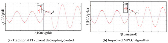
Figure 11.
Grid-side current waveform when the inner loop is given a sudden change.
Table 3.
Comparison of three control methods.
6. Conclusions
This paper uses a single-phase five-level rectifier to improve the traditional model predictive current control algorithm for a fixed switching frequency. The new algorithm reduces the grid-side current harmonics, improves the system’s dynamic response speed, and simplifies the calculations. The following conclusions have been obtained through simulation and experiments. To solve the problem of system delay, the improved MPCC algorithm predicts the current at the (k + 2) moment, so that the variable at the (k + 1) moment is directly linked to the (k + 2) moment. This procedure improves the speed of grid-side current tracking and reduces the system delay error. A modulation function is introduced to solve the problem that the conventional model predicts that the current control switch is not fixed. The modulation function of the system is obtained by deriving the objective function. The modulation module effectively fixes the switching frequency. This new algorithm effectively reduces the harmonic distortion rate of the grid-side current, while retaining the advantages of model predictive control. As a result, the system’s calculation complexity is reduced.
In addition to this type of rectifier, he improved MPCC algorithm can be used on other single-phase rectifiers. However, this algorithm needs further study and discussion for use in three-phase systems, as this configuration was not studied in this paper.
Author Contributions
Y.Z. and H.Y. conceived and designed the framework for the control algorithms. H.X. drafted the charter. H.Y. and H.Z. performed simulations and experiments. D.W. supervised that effort. H.Y. created the diagram and the figures. Y.Z. provided guidance and reviewed the various drafts of this paper. Y.Z. and H.Y. purchased the equipment and supervised the funding of this project. All authors have read and agreed to the published version of this manuscript.
Funding
This work was jointly supported by the National Natural Science Foundation in China (No. U1504518) and by the Innovative Scientific and Technological Team of Mine Power Electronic Devices and Control in Henan Province.
Acknowledgments
This work was supported in part by the National Natural Science Foundation in China (No.18A410001), the Innovative Scientific and Technological Team of Mine Power Electronic Devices and Control in Henan Province, and also by EditSprings. In addition, the authors would like to thank the reviewers for their valuable comments which improved the quality of this paper.
Conflicts of Interest
The authors declare no conflicts of interest.
References
- Zhang, X.; Zhang, C. PWM Rectifier and Control; China Machine Press: Beijing, China, 2012; pp. 1–13. [Google Scholar]
- Lu, Z.; Ge, Q. A Novel Single-Phase Five-Level Rectifier with Coupled Inductors. In Proceedings of the 2013 International Conference on Electrical Machines and Systems, Busan, Korea, 26–29 October 2013; pp. 1814–1819. [Google Scholar]
- Jose, R.; Patricio, C. Predictive Control of Converters and Electrical Drives; China Machine Press: Beijing, China, 2015; pp. 45–53. [Google Scholar]
- Dahono, P.A. New hysteresis current controller for single-phase full bridge inverters. IET Power Electron. 2009, 2, 585–594. [Google Scholar] [CrossRef]
- Papafotiou, G.; Kley, J.; Papadopoulos, K.G. Model predictive direct torque control-Part II: Implementation and experimental evaluation. IEEE Tran. Ind. Electron. 2009, 56, 1906–1915. [Google Scholar] [CrossRef]
- Kouro, S.; Cortes, P.; Vargas, R.; Ammann, U. Model predictive control—A simple and powerful method to control power converters. IEEE Tran. Ind. Electron. 2009, 56, 1826–1838. [Google Scholar] [CrossRef]
- Vazquez, S.I.; Leon, J.G.; Franquelo, L.; Rodriguez, J. Model predictive control: A review of its applications in power electronics. IEEE Tran. Ind. Electron. 2014, 8, 16–31. [Google Scholar] [CrossRef]
- Cortés, P.; Rodríguez, J. Predictive current control strategy with imposed load current spectrum. IEEE Tran. Power Electron. 2008, 23, 612–618. [Google Scholar] [CrossRef]
- Zhang, Y.; Peng, Y. Model Predictive current control with optimal duty cycle for three-phase grid-connected AC/DC converters. In Proceedings of the 2014 International Power Electronics and Application Conference and Exposition, Shanghai, China, 5–8 November 2014; pp. 837–842. [Google Scholar]
- Geyer, T.; Oikonomou, N.; Papafotiou, G.; Kieferndorf, F.D. Model predictive pulse pattern control. IEEE Trans. Ind. Appl. 2012, 42, 663–676. [Google Scholar] [CrossRef]
- Hu, J.; Zhu, Z. Improved voltage-vector sequences on dead-beat predictive direct power control of reversible three-phase grid-connected voltage-sourced converters. IEEE Trans. Power Electron. 2013, 28, 254–267. [Google Scholar] [CrossRef]
- Antoniewicz, P.; Kazmierkowski, M.P. Virtual-flux-based predictive direct power control of ac/dc converters with online inductance estimation. IEEE Trans. Ind. Electron. 2008, 55, 4381–4390. [Google Scholar] [CrossRef]
- Gregor, R.; Barrero, F.; Toral, S.; Duran, M.J.; Arahal, M.; Prieto, J.; Mora, J. Predictive-space vector PWM current control method for asymmetrical dual three-phase induction motor drives. IET Electr. Power Appl. 2010, 4, 26–34. [Google Scholar] [CrossRef]
- Barrero, F.; Arahal, M.; Gregor, R.; Toral, S.; Durán, M.J. One step modulation predictive current control method for the asymmetrical dual three-phase induction machine. IEEE Trans. Ind. Electron. 2009, 56, 1974–1983. [Google Scholar] [CrossRef]
- Vazquez, S.; Montero, C.; Bordons, C.; Franquelo, L.G. Model predictive control of a VSI with long prediction horizon. In Proceedings of the 2011 IEEE International Symposium on Industrial Electronics, Gdansk, Poland, 27–30 June 2011; pp. 1805–1810. [Google Scholar]
- Stolze, P.; Landsmann, P.; Kennel, R.; Mouton, T. Finite-set model predictive control with heuristic voltage vector preselection for higher prediction horizons. In Proceedings of the 2011 14th European Conference on Power Electronics and Applications, Birmingham, UK, 30 August–1 September 2011; pp. 1–9. [Google Scholar]
- Marks, N.D.; Summers, T.J.; Betz, R.E. Finite control set model predictive control with increased prediction horizon for a 5-level cascaded H-bridge STATCOM model predictive control for power converters. In Proceedings of the 2013 15th European Conference on Power Electronics and Applications, Lille, France, 2–6 September 2013; pp. 1–10. [Google Scholar]
- Vazquez, S.; Montero, C.; Bordons, C.; Franquelo, L.G. Design and experimental validation of a model predictive control strategy for a VSI with long prediction horizon. In Proceedings of the IECON 2013—39th Annual Conference of the IEEE Industrial Electronics Society, Vienna, Austria, 10–13 November 2013; pp. 5788–5793. [Google Scholar]
- Fang, H.; Zhang, Z.; Feng, X. Ripple-reduced model predictive direct power control for active front-end power converters with extended switching vectors and time-optimised control. IET Power Electron. 2016, 9, 1914–1923. [Google Scholar] [CrossRef]
- Oettmeier, M.; Heising, C.; Staudt, V.; Steimel, A. Dead-beat control algorithm for single-phase 50-kW AC railway grid representation. IEEE Trans. Power Electron. 2010, 25, 1184–1192. [Google Scholar] [CrossRef]
- Deng, Z.; Song, W.; Cao, M. A Model Predictive Current Control Scheme for Single- phase PWM Rectifiers. Proc. CSEE 2016, 36, 2996–3004. [Google Scholar]
- Yang, L.; Yang, S.; Zhang, W. The Improved Deadbeat Predictive Current Control Method for Single-phase PWM Rectifiers. Proc. CSEE 2015, 35, 5842–5850. [Google Scholar]


© 2020 by the authors. Licensee MDPI, Basel, Switzerland. This article is an open access article distributed under the terms and conditions of the Creative Commons Attribution (CC BY) license (http://creativecommons.org/licenses/by/4.0/).