Article

Low Voltage Battery Management System with Internal Adaptive Charger and Fuzzy Logic Controller

by
Omer Faruk Goksu
1,
Ahmet Yigit Arabul
2,* and
Revna Acar Vural
3
1
Department of Electrical and Electronics Engineering, Fatih Sultan Mehmet Vakif University, Istanbul 34445, Turkey
2
Department of Electrical Engineering, Yildiz Technical University, Istanbul 34220, Turkey
3
Department of Electronics and Communications Engineering, Yildiz Technical University, Istanbul 34220, Turkey
*
Author to whom correspondence should be addressed.
Energies 2020, 13(9), 2221; https://doi.org/10.3390/en13092221
Submission received: 30 March 2020 / Revised: 25 April 2020 / Accepted: 29 April 2020 / Published: 2 May 2020
(This article belongs to the Special Issue Testing and Management of Lithium-Ion Batteries)

Abstract

:
Lithium ion (Li-Ion) and lithium polymer (Li-Po) batteries need to be used within certain voltage/current limits. Failure to observe these limits may result in damage to the battery. In this work, we propose a low voltage battery management system (LV-BMS) that balances the processes of the battery cells in the battery pack and the activating-deactivating of cells by guaranteeing that the operation is within these limits. The system operates autonomously and provides energy from the internal battery. It has a modular structure and the software is designed to control the charging and discharging of eight battery cells at most. A STM32F103 microcontroller is used for system control. The fuzzy logic controller (FLC) is used to set the discharge voltage limit to prevent damage to the battery cells, shorten the settlement time and create a specialized design for charge control. The proposed structure enables solar panel or power supplies with different voltage values between 5 V and 8 V to be used for charging. The experimental results show there was a 42% increase in usage time and the voltage difference between the batteries was limited to a maximum of 65 mV. Moreover, the charge current settles at about 20 ms, which is a much faster response when compared to a PID controller.

1. Introduction

Due to the increment in the energy requirements of portable devices, battery types with a high power density and low self-discharge rate are being developed. Among these, Li-Ion and Li-Po batteries have become prevalent for energy storage. This is due to their high cell voltage and high continuous current values. However, high charging and discharging rates may damage the battery and eventually the maximum battery capacity and battery lifetime may decrease. Therefore, the battery voltage, current, and operating temperature should remain within certain limits in order to avoid any damage to the battery and to prevent explosions and fires [1,2,3,4].
Advanced battery management systems (BMS) requires cell equalizers to correct the imbalance among the cascaded cells. This may occur because of manufacturing, degradation with aging, an imbalance between the charge and discharge, and differences in thermal conditions, internal impedances and the self-charge rate [5,6]. These management systems are designed in two basic configurations, central and modular. The modular structure employs a master module, to which each battery module is connected. In the central structure, the batteries are connected to a single module where the number of batteries that can be connected is fixed [7,8,9].
Minor differences can occur between the same type, same brand and model batteries, which prevents the batteries from being consumed equally. This mismatch causes differences in the duration of the usage and the maximum amount of energy that can be stored. In order to avoid this situation, several different balancing methods have been developed; these are categorized as passive or active methods according to their energy dissipation. One of the critical drawbacks of passive balancing is energy wastage in advanced high-performance battery systems. Rather than wasting energy to improve efficiency, active balancing may be preferable when the number of cells is small, although the equalization becomes less efficient and slower when the number increases. Efficient use of balancing methods not only increases battery usage time, but also extends battery life [10,11,12,13,14].
Novel structures have been developed to allow the cells in the battery pack to be switched on and off independently. In the centralized BMS design, an opamp based monitoring unit is used for voltage measurement of cells, which can be controlled independently of each other. This unit is basically a differential receiver and measures the potential difference between battery terminals. For the correct measurement of disused cells, the opamp used in this unit requires a supply voltage above the nominal voltage rating of the battery pack [15,16]. Modular BMSs can easily be customized at different power and voltage levels by attaching different numbers of building blocks together and being plugged directly into the application. Easy modification of the modular systems and the support of variable battery counts offers great advantages over centralized systems [17]. In such systems, the ground line of each module is independent. Each battery must be charged separately to prevent short circuits during the charging of the batteries in use [18,19,20,21]. However, to the knowledge of the authors, a modular structure that performs the charging process during discharge has not yet been studied.
Numerous control methods have been developed for BMSs. The on-off values of the battery pack are determined according to the usage limits of the battery [22,23]. Since the value of the discharge limit is determined according to the types of battery that are used, the shutdown voltage level can be set high to protect the batteries, even though there is enough energy for the system to operate in low power consumption systems. Several studies have also aimed to extend the service life of the battery pack and to perform battery balancing by closing the cells in the package and re-engaging them during use [24]. The cell with the lowest voltage is selected in the package for determining the closed cells. Although this structure increases efficiency during use, it still requires more battery cells to obtain the required voltage level. Fuzzy logic control is intended to solve problems that cannot be determined precisely and cannot be predicted [25]. The fuzzy logic method is meant to imitate people’s ability to react and predict. Moreover, it has been observed that systems controlled using fuzzy logic are less complex and perform better than many other systems [26,27,28].
Often, BMSs do not have internal chargers. Therefore, an external charger is needed. An external charger is selected according to the number of batteries and charging method. All batteries must be activated for charging. For this reason, the use of the battery must be damped during charging [15,16,17]. Internal chargers are designed for a configurable and an adaptable charging system. Thus, the charging system should be independent from the number of batteries. Independent charging can be carried out with low voltage values such as 5 V. Batteries can be charged in parallel to shorten the battery charging time. Charging and output lines must be isolated from each other in order to charge the series connected batteries in parallel; thus, relay is used for isolation [11,28].
Charging techniques play an important role in ensuring that the batteries are healthy and long lasting. There are several basic charging methods that are frequently used: constant current, voltage and alternating. Although they are easy to apply, battery life has been observed to decrease after long-term use when these methods are applied [29,30,31,32]. In recent decades, pulse charging has become a popular charging method that utilizes the average values of voltage and current and includes short-term rest intervals during the charging process. In these intervals, the chemical structure of the battery is regulated and the necessary voltage measurements are reliably made. In addition, it provides better charging capacity, less wear and fast application [33,34,35]. In order not to damage the batteries, pulse method parameters should be carefully selected by determining the optimum charge length and frequency [36,37].
Because of its high efficiency, FLC has found widespread application in the field of control systems. This method is based on the knowledge and experience of experts and does not require precise numerical modeling of the system. Since the battery charge and discharge process is complicated, a robust and efficient controller is required. The results in [38,39,40] imply that FLC is capable of improving charging time, charging efficiency, states of charge (SOC), and battery life expectancy.
The aim of this study was to develop a low voltage modular BMS system with high efficiency and where the batteries are extruded when necessary. The proposed system is able to control and charge a single battery cell when the batteries are active or inactive. It is designed to operate with different battery types and to use various sources for charging. The battery control unit and charging unit employ metal oxide semiconductor field effect transistors (MOSFET) as switching components for low power consumption. Due to the low gate-source voltage of MOSFETs, no external DC-DC voltage regulator or MOSFET gate driver is required. Energy for switching is supplied directly from the batteries. In addition to these contributions, the performance of the PID controller and FLC were evaluated within the control unit.
Following the introduction, Section 2 presents the architecture of the proposed low voltage BMS (LV-BMS). Section 3 introduces the control algorithms of LV-BMS, which are run on a microcontroller and are used for charging and discharging. The experimental results are discussed in Section 4. Finally, the concluding remarks are presented in Section 5.

2. LV-BMS Architecture

The proposed system is designed to combine the functions of cell balancing, charger, discharger, cell monitor, and protection. These functions are carried out autonomously and the energy is provided from the internal battery. Furthermore, the proposed system is flexible, modular and extensible. It can be used with Li-Ion and Li-Po type batteries due to their similar usage limits. To accomplish the aim of the study, extruded batteries should be charged with active batteries. However, batteries must be connected in series to charge in general BMS. To overcome this problem, the battery charging line is connected in parallel and charging is carried out with low voltage by using parallel charging lines.
The system consists of 4 units: the control unit, battery switching unit, measurement unit and charging unit. The control unit processes the data it collects from the measurement unit and determines the condition of the battery switching unit and charging unit. The measurement unit monitors the battery voltage and the instantaneous current of the battery. The battery switching unit ensures that the battery is isolated from the power line. The charging unit implements charging algorithms for different battery packs and battery types. A block diagram of the LV-BMS is given in Figure 1.
In order to achieve low power consumption, transistors with low drain-source resistance (Rds) were selected. MOSFETs can be switched via logic levels to avoid the usage of an external gate driver. The microcontroller is selected to have low power consumption and operate directly with the battery voltage range. Foregoing the voltage regulator also decreases the total power consumption. The energy that needs to be supplied from the batteries is reduced because the energy required for the charging structure is provided by the charging line. Table 1 contains the list of components used in the LV-BMS architecture.
IRLML series MOS transistor switching with logic voltage level and low Rds were selected as switching components in the units. Consequently, switches can be operated with battery power and do not require gate driver IC. The specifications of the MOSFETs are given in Table 2.

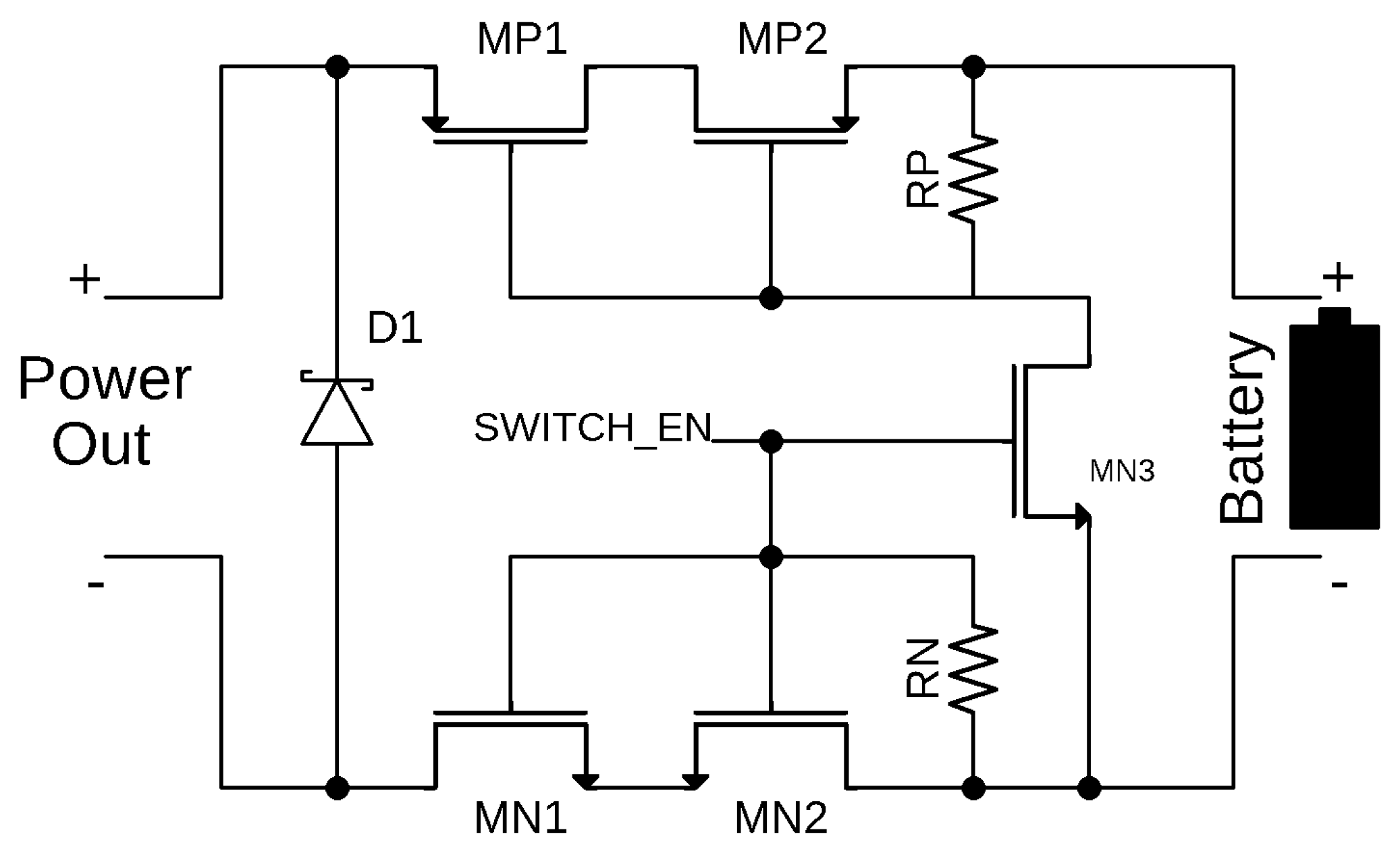
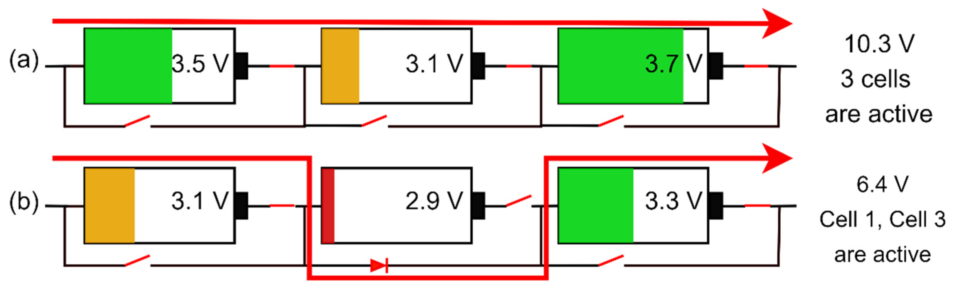
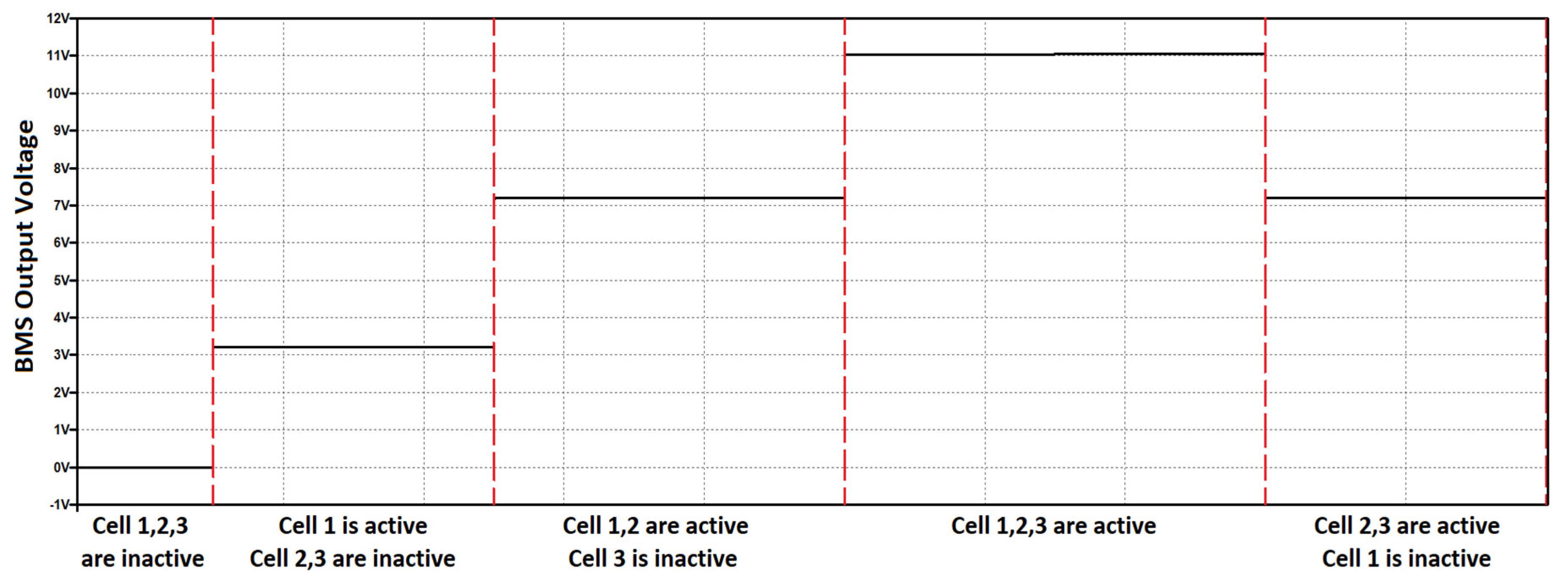
2.1. Battery Switching Unit

The battery switching structure consists of five MOSFETs and a schottky diode. NPN MOSFET is used as the auxiliary element for the control of PMOS transistors. The switching unit is located in each module. The energy for the unit is provided by the battery. The gate signal of the auxiliary MOSFET is provided directly by the microcontroller. Due to the low Rds resistance of the MOSFETs used in the switching unit, an external gate driver and voltage converters are not used.
A schematic of the battery switching unit is shown in Figure 2. The charging of the batteries can also be performed while the batteries are discharged. As a result, the complexity of the structure is simplified and the number of components used in the structure is reduced.
The drain nodes of the PMOS transistors are connected to each other and the source nodes of the NMOS transistors are connected to each other. According to the connection of the transistors, the battery is separated from the power line. The gate voltages of PMOS and NMOS transistors are connected to the positive and negative terminals of the battery using pull-up and pull-down resistors, respectively, so it is ensured that transistors are turned off. When the gate signal of MN3 is increased by the microcontroller, the MOSFETs (MN1, MN2, MP1, MP2) are turned on and connect the batteries to the power line.
Battery pack configuration examples are provided in Figure 3. In Figure 3a, all three cells are active and the total voltage of the cells is 10.3 V. In Figure 3b, two cells are active and the second battery is out of use, and the energy stored by the batteries that are available for use is transferred to the power line through transistors. After the second battery is excluded from the system, the current flows through the diode element in the transmission mode.
The results of the switching unit simulation is provided in Figure 4. The batteries are activated sequentially and then deactivated, and the output voltage is observed. It is observed that there is no current flow between the isolated batteries and the power line. The switching voltage of the MOSFETs used in the simulation was chosen as 3 V considering the battery limits.

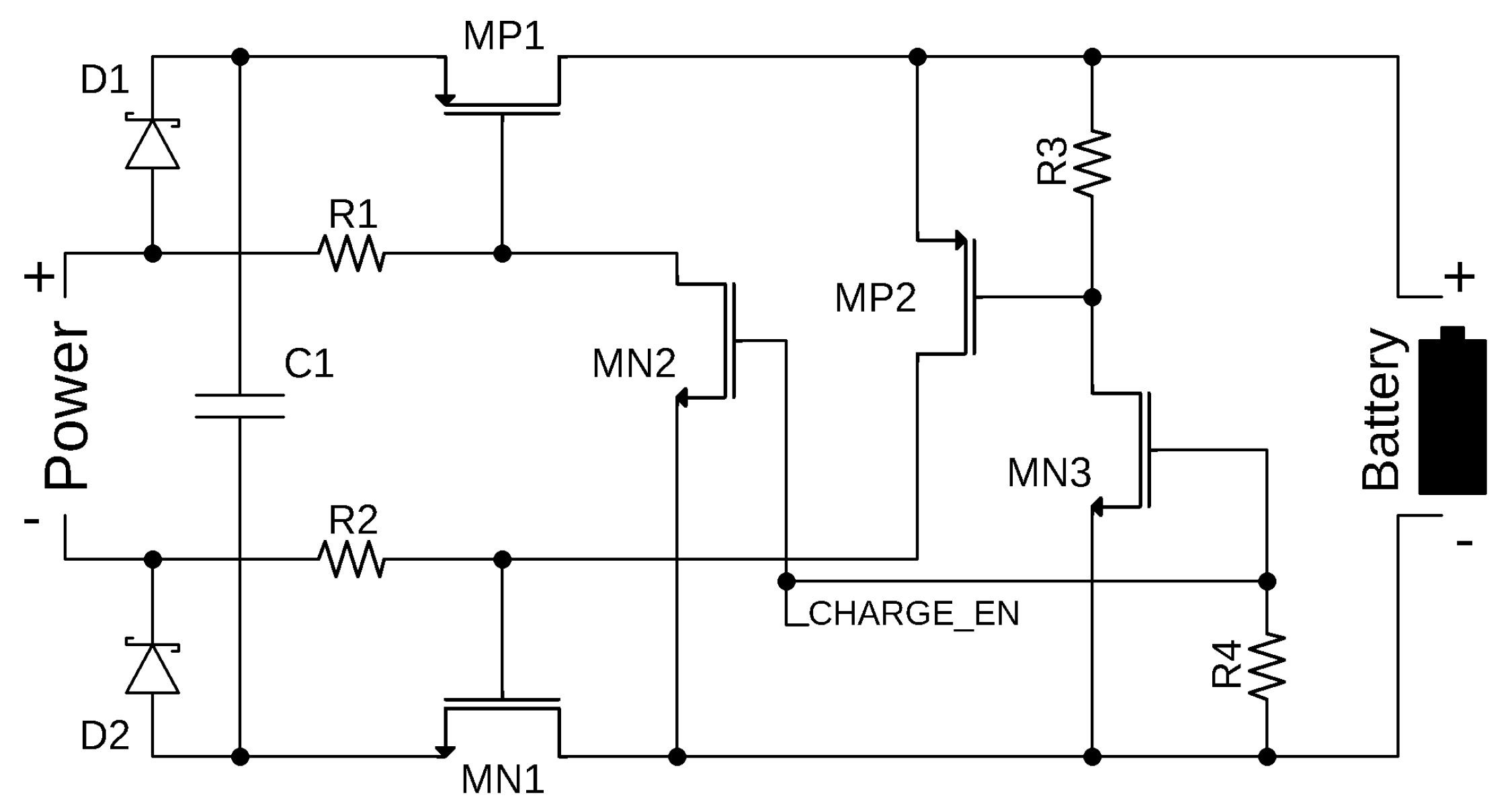
2.2. Battery Charging Unit

One of the purposes of this study was to charge the serial connected cells with a low voltage such as 5 V. In this regard, the batteries should be charged in parallel. Thanks to the proposed structure, solar panel and power supplies with different voltage levels can be used for charging. The charging unit supports up to 2 A charging current and for a 5–8 V input voltage range; but the charging current is software-limited to 1.2 A in order to avoid problems during use with different battery models.
Figure 5 shows the schematic of the charging unit. Gate voltages of MP1 and MN1 are not directly connected to the battery cells. When the charging source is connected, the gate voltages are provided by the charge line via diodes D1 and D2. When the charging adapter is not connected, the C1 capacitor is charged from the battery cell via MOSFET body diodes and MOSFET gate voltages are supplied by this stored energy. In this way, the gate voltages of the transistors are provided continuously and the MP1-MN1 transistors remain off.
The gate voltage of the MP2 transistor is equal to the positive voltage level of the battery via R3. MN2 and MN3 transistors are equalized to the negative voltage level of the battery via R4. When “CHARGE_EN” signal is low, MN2 and MN3 transistors are off and the charging line and the battery are separate from each other. If the “CHARGE_EN” signal is changed from low to high, the MP1 transistor is activated via MN2 and MN1 transistors are activated via MP2 and energy is transferred from the charging line to the battery.
Connecting the batteries in series can cause a short circuit during parallel charging. In order to avoid short circuits between the batteries, the charging process must be applied to the batteries sequentially and batteries must not be charged simultaneously. However, if the battery is removed from the battery pack, it is no longer connected in series. Therefore, the removed batteries can be charged at the same time.

2.3. Battery Control Unit and Battery Measurement Unit

The control unit processes the data from the measurement unit and provides control of the switching and charging units. The signals from the measurement units are read with the analog digital converter (ADC) peripheral, which is located inside the microcontroller. Battery management is provided with control algorithms run on the microcontroller. The LV-BMS control algorithms are introduced in Section 3.
The voltage limit of the ADC unit remains below the battery operating range. A voltage divider is used to convert the battery voltage to the proper level. One of the limits to be considered during battery charge and discharge is the value of the battery current. In order to measure current with microcontroller, a current-voltage converter structure is utilized.
ADC resolution is set to 12 bits and interrupt mode is enabled with direct memory access. With this configuration, the battery voltage value is measured with an accuracy of 1 mV. Measurements are carried out automatically via DMA and ADC units, thus reducing the software load.
A shunt resistor is used to measure battery current and it is connected to the battery in series. The voltage of the resistor has been converted to the value that can be measured by the ADC using the differential amplifier, INA214. The battery current generates a voltage value that does not affect the output voltage of the resistor. The value of this voltage is increased 100 times by INA214 and transmitted to the ADC unit.
The INA214 reference voltage value is set to 1.65 V, thereby allowing positive and negative battery current to be measured. An RC filter is used to prevent the hardware noise that may occur on the ADC input signals. Passive component values are determined for the desired cutoff frequency using Equation (1).
f c = 1 ( 2 × π × R × C )
In order to obtain a cut-off frequency of 20 Hz, the capacitor and resistor values were selected as 1 µF and 8 kΩ, respectively.

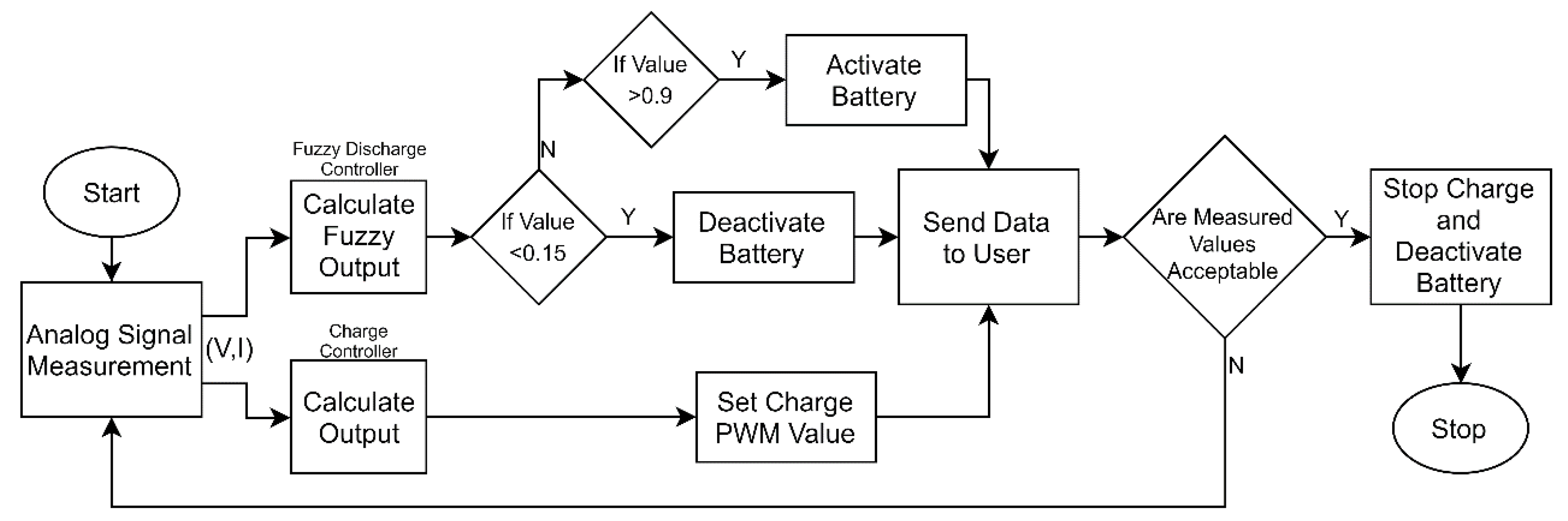
3. LV-BMS Control Algorithms

The STM32F103 microcontroller was used for LV-BMS control. The developed software processes the data from the measurement units and manages the battery control unit and charging units. The generalized battery charge/discharge control algorithm flow chart is shown in Figure 6.
The BMS has an expandable structure. Therefore, when changing the number of connected modules at system startup or during operation, the number of modules is automatically calculated and the system continues to operate. The BMS software is designed to control the charging and discharging of eight battery cells at most.

3.1. Discharge Control

The BMS software ensures that the battery operates properly. In case of possible operation outside of the specified limits, the BMS must shut down the system and keep the battery pack safe. Fuzzy logic combined with the threshold method is applied for the discharge control on the microcontroller.

3.1.1. Threshold Method

The threshold control method, which is an easy-to-use control method, is preferred to reduce the software load. With this method, a closing command is sent to the on-off unit when the battery is outside of the limits and the decision to open and close is made with certain rules. The battery is not activated until it is charged up to the lower limit value. During use, the battery is turned off after it drops below the specified value.
The threshold method input value is determined by the FLC. The FLC output takes a value between 0 and 1. Two values have been determined to either exclude the battery from the battery pack or include the battery in the battery pack during the battery discharge control design. Here, the batteries are manually controlled and charge-discharge processes are carried out. As a result of these procedures, the values that will ensure the proper operation of the batteries were determined to be 0.15 and 0.9. If the value is below 0.15, the battery is excluded and charged. The excluded battery is included in the battery pack again when the value reaches 0.9.

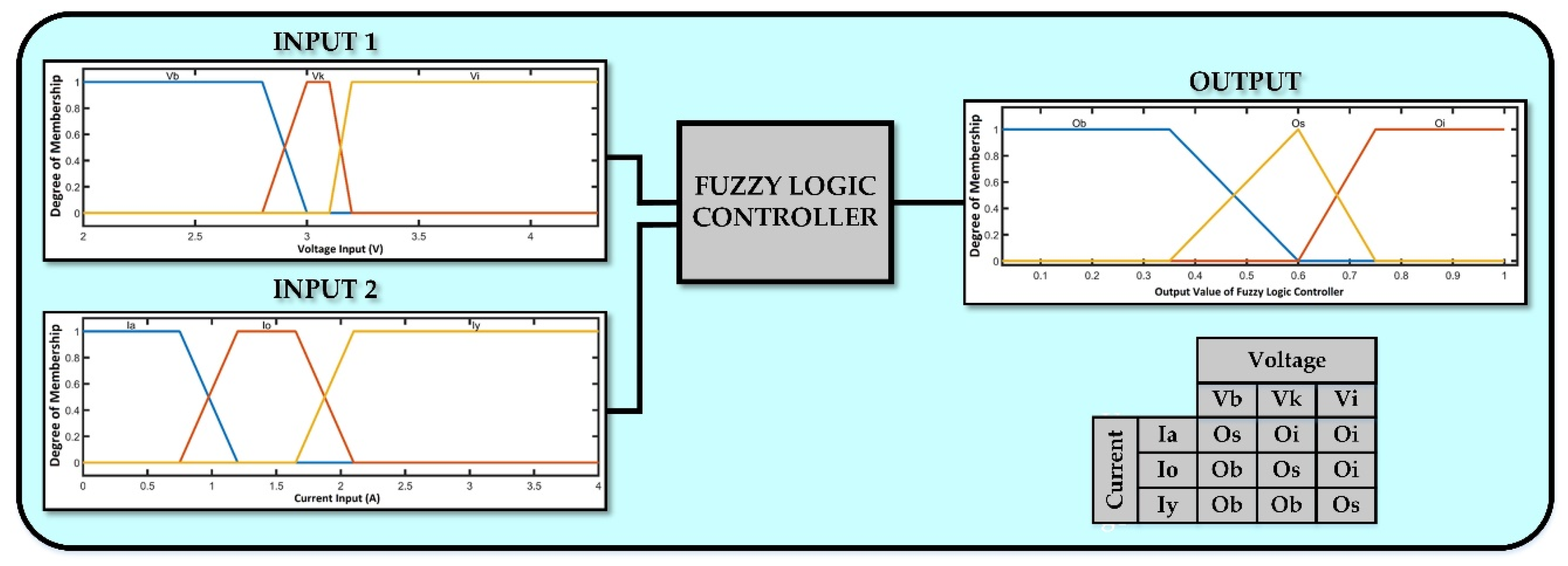
3.1.2. Fuzzy Logic Controller

In some cases, the load draws too much current from the batteries. This causes a sudden drop in battery voltage. The batteries do not need to be deactivated in the case of high current draw for a short time. However, if the threshold control method is used as standalone, the system shuts down the battery pack in case of voltage drop. FLC decides whether the voltage drop is short-term and ensures healthy use of the battery. The fuzzy logic control algorithm utilizes the Mamdani method [41,42] and is designed in “MATLAB Fuzzy Logic Tool”.
The FLC is used to set the discharge voltage limit to prevent damage to the battery cells. After the voltage limit is set, the threshold method is executed. The controller has two inputs and one output. Each input has three membership functions. Input 1 represents the measured battery voltage value and input 2 represents the measured battery current value.
FLC with the threshold method for discharge is shown in Figure 7. The fuzzy logic decision mechanism uses battery voltage and battery current values as input data. According to the voltage/current values of each battery, FLC can map these values to the interval (0, 1) using a rule set. Excluded cells are not included in the system after being charged until the operable voltage value is reached. If the re-included battery voltage is lower than the voltage values of other batteries in the pack, charging continues.
FLC systems are based on expert opinion. Membership function values are determined based on experience. During the battery discharge process, battery behaviors were observed under different loads and the data were recorded. From the data, 3 voltage and 3 current membership functions were created by considering the operating conditions of the battery. The points where significant changes in the data are determined as the start and stop values of the functions. The FLC system, which is operated autonomously, was observed during the study and minor corrections were made to the function values. The same calculation technique was carried out in the FLC charge control.
The membership functions of input 1 are Vi, Vk and Vb, which represent the good, average and empty level of battery voltages, respectively. The membership functions of input 2 are Iy, Io and Ia. Iy represents current values between 1.6 A and 4 A. Io represents current values between 0.6 A and 2.1 A. Ia represents current values from 0 A to 1.2 A. The membership functions of output are Ob, Os, Oi as given in Figure 7. The output value interval is (0, 1). FLC first calculates the membership functions according to the inputs applied, as in Equation (2).
I f   I n p u t   1 = x   a n d   I n p u t   2 = y   ,             z i = m i n ( x , y )
Weight values are calculated by fuzzification of the output of membership functions according to the inputs as given in Equation (3). Using the weight values and z values, the output value of FLC is obtained from Equation (4).
w i = z i o u t p u t i
F L C   O u t p u t = i = 1 N w i z i i = 1 N w i

3.2. Charge Control

Battery charge control ensures safe and balanced charging of the batteries included in the system. Since the charging method recommended by the manufacturers of the batteries is compatible with the constant current constant voltage (CCCV) system, this method was used as the fundamental method. It is a two-step method that uses both constant current and constant voltage. In the first stage, constant current is applied until the battery voltage reaches the specified level. In the second stage, constant voltage mode is switched on to prevent overvoltage. Additionally, in this method, since the batteries are continuously charged, the battery is prevented from resting. This causes a chemical strain on the batteries. With the inclusion of the pulse method, the advantages of both methods are combined. The energy provided for charging is transferred to the battery as a pulse. The pulse width is determined by the charge controller. The voltage and current data provided to the controllers consist of the average voltage and current data of the battery. It has been determined in the literature [37] that the chemical structure of the battery helps to stabilize the battery when the pulse is at the logic-0 level. Combining the advantages of both CCCV and pulse method results in a longer battery life and the stable operation of the battery. The PID controller and FLC are designed to control charging and their performances were compared.

3.2.1. PID Control

In order to shorten the settlement time of the system, the proportional gain should be kept high and as a result, bouncing was observed in the charging current. The gain values were determined as P = 0.1 (proportional gain), I = 12 (integral gain) and D = 0 (derivative gain) to achieve a stable charge current without bouncing. The settlement time with the given gain values is 80 ms.

3.2.2. Fuzzy Logic Control

Fuzzy logic is used to shorten the settlement time and create a specialized design for charge control. The designed controller has two inputs and one output. The first input is the difference between the instantaneous battery voltage and target voltage. The second input is the difference between the instantaneous battery charge current and target current. The controller output adjusts the pulse width modulation (PWM) change value. The membership functions of inputs and output are given in Figure 8.
The FLC charge scheme is given in Figure 8. The fuzzy logic decision mechanism uses battery current and battery voltage values as input data. According to the voltage/current values of each battery, FLC can map these values to the interval (0, 1) using a rule set. If the re-included battery voltage is lower than the voltage values of other batteries in the pack, charging continues.
The membership functions of input 1 are −3 to 3, which represent the levels of battery currents, respectively. Membership functions of input 2 are Vz, Vr1 and Vr2. Vz, which represent voltage values between −1 and −0.1 V. Vr1 represents voltage values between −0.5 V and 0.3 V. Vr2 represents voltage values from −0.1 to 1 V. The membership functions of output are p4−, p3−, p2−, p1−, p0, p1+, p2+, p3+, p4+ as shown Figure 8. The output value interval is (−80, 80).

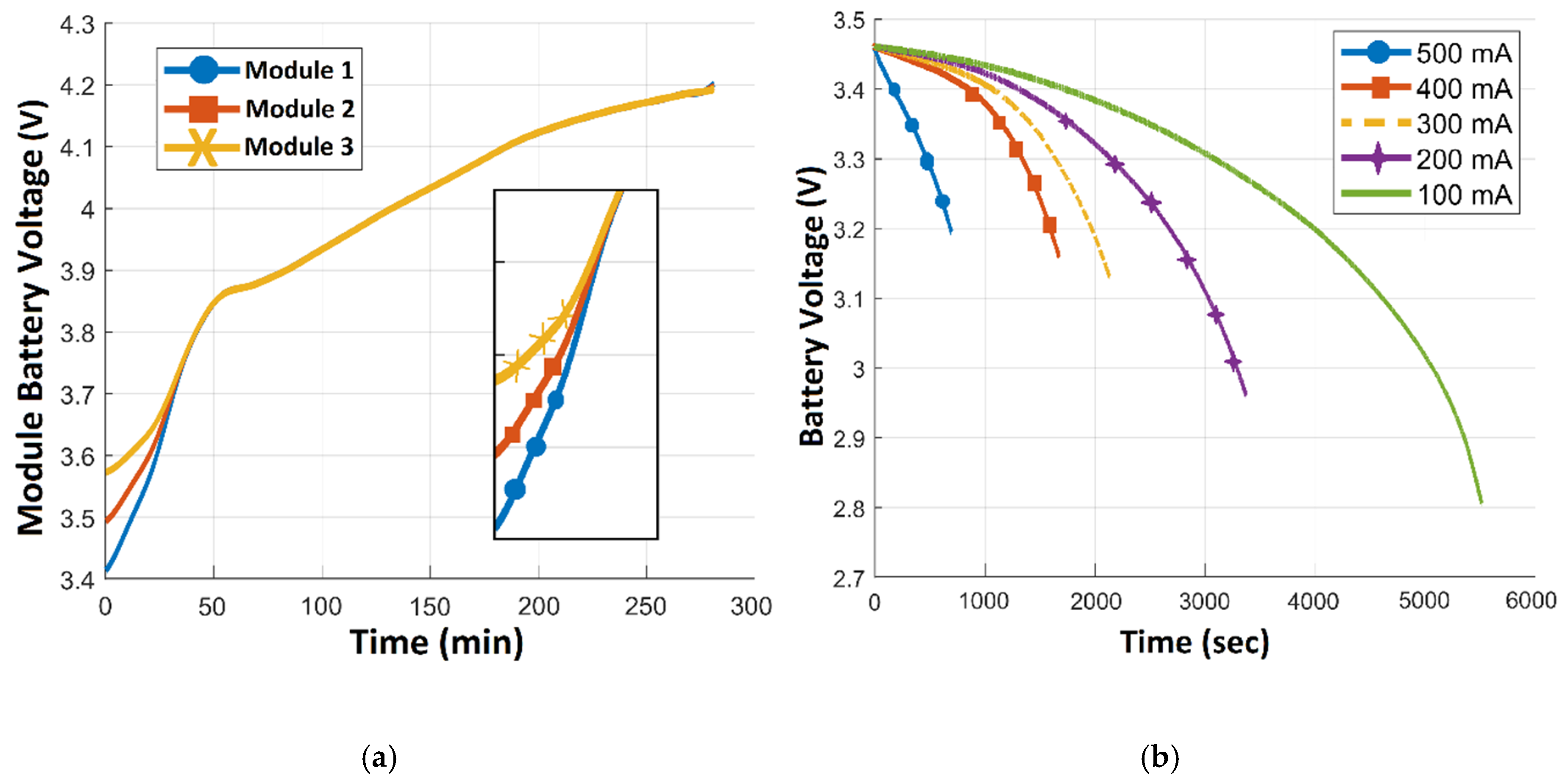
4. Experimental Results

The printed circuit board (PCB) of the designed module with a stepper motor connected as load is shown in Figure 9. The modules can be expanded by connecting to each other with a socket. The stepper motor and driver, whose current can be adjusted were used as test load.
According to the manufacturer, 2.9 V is the lowest voltage level at which the batteries can operate. However, as the battery voltage decreases, the voltage drop rate increases. This results in a faster drop in battery voltage at higher current levels. The designed LV-BMS modules provide their energy from the battery. In order to control the batteries and communicate within the modules, the modules must continue to function so the default threshold level is set at 3.2 V. Thanks to the fuzzy logic control applied, when the current drawn from the battery is low, the deactivation voltage level of the battery is lower and as a result, the usage time increases.
For instance, when the battery drops to 3.2 V at a current level of 500 mA, the battery is deactivated. However, as the current level decreases, the drop in battery voltage will decrease; so, the battery shutdown voltage level is also reduced. Thanks to this control system, although the usage time is extended at low load levels, the LV-BMS module always maintains its functionality.
The discharge values of the battery cell according to different currents is given in Figure 10b. The battery is discharged at the specified constant current values until it drops to the default threshold and FLC threshold. Based on this figure, the increase in usage times and low voltage limits provided by the FLC of the LV-BMS are given in Table 3. According to the test results, there was a 42% increase in usage time.
The LV-BMS has adaptive charging units. These units provide charge priority to the modules according to battery charge levels. High priority battery modules have higher PWM duty cycles than other modules. Batteries with low voltage are charged with higher current compared to other batteries, and thus, the balancing process of the batteries is carried out in this way (Figure 10a). Charge and discharge values of the battery pack are given in Figure 11. After the balancing process is complete, the voltage difference between the batteries is limited to 65 mV at most.
In the experimental studies, two controllers were used for battery charging. First, the PID controller was used and the charge current vs. time graph was obtained as shown in Figure 12a. As a result of using the PID controller, the battery charge current settled to the desired value in 80 ms. In addition, this method did not exceed the target value, and no current fluctuations were observed. Then, the FLC controller was used and the charge current vs. time graph was obtained as shown in Figure 12b. Although there was a fluctuation in the battery current, the current settled at about 20 ms, which is a much faster response when compared with the PID controller.
The variations in the charge and discharge efficiency of the proposed LV-BMS are given for a battery pack with three cells in Figure 13. Efficiency measurements were carried out by measuring the energy consumed by the switching components of the module. The discharge efficiency varied according to the battery voltage and configuration type because the switching components of the modules have different features that keep the battery active and deactivated. Since the energy used on the charging unit changes in direct proportion with the charging current, the efficiency decreases as the charge current increases.
A comparison of this study with previous studies in the literature is shown in Table 4. This study uses ADC input to directly monitor the battery voltage. In this way, the modularity of the proposed system is increased and the requirement of having a common GND line is removed. In addition, the absence of an external voltage monitoring IC reduces the complexity of the software and hardware. Given its compact internal charging unit, the charging voltage of the proposed system is between 5 V and 8 V, which enables operation with different power sources. Since the battery configuration is modular, it can be used with different battery packs. The same structure and charging source can be used for up to eight batteries.

5. Conclusions

An accurate, modular and compact LV-BMS with a power-efficient internal adaptive charger was presented and experimentally verified. The system combines the functions of cell balancing, charging, discharging, cell monitoring, and protection. High efficiency was obtained by selecting a low power microcontroller that operates directly with a range of battery voltages by using MOSFET components that can be switched via logic levels. This avoids the usage of an external gate driver and results in low voltage drops across the drain source resistance. Moreover, a voltage regulator is not required and this decreases the total power consumption as well.
The experimental results showed that the proposed system extends the usage time of the battery cell with fuzzy logic and threshold value control software. The voltage level required for charging varies between 5 V and 8 V, which allows different voltage sources to be used. At the same time, charging can be carried out during use, which allows the batteries to be used for an increasing amount of time with alternative sources such as solar panels. Combining the advantages of both CCCV and the pulse method results in a longer battery life and the stable operation of the battery. According to the experimental results, a 42% increase in usage time was observed and the voltage difference between the batteries was limited to a maximum of 65 mV.
Consequently, the proposed circuit optimally charges a Li-Ion battery with minimal power losses, increasing the life of battery charge cycles and avoiding the need for bulky heat sinks, all of which incur costly tradeoffs in mobile electronics. As a further work, an estimation of the aging of the proposed system will be considered. Moreover, its efficiency for higher voltage/current ratings will be investigated.

Author Contributions

All authors worked on conceptualization, methodology, software, validation, formal analysis, writing—original draft preparation, writing—review and editing. All authors have read and agreed to the published version of the manuscript.

Funding

This research received no external funding.

Conflicts of Interest

The authors declare no conflict of interest.

References

  1. Teofilo, V.L.; Isaacson, M.J.; Higgins, R.L.; Cuellar, E.A. Advanced Lithium Ion Solid Polymer Electrolyte battery development. IEEE Aerosp. Electron. Syst. Mag. 1999, 14, 43–47. [Google Scholar] [CrossRef]
  2. Horiba, T. Lithium-ion battery systems. Proc. IEEE 2014, 102, 935–950. [Google Scholar] [CrossRef]
  3. Asumadu, J.A.; Haque, M.; Vogel, H.; Willards, C. Precision battery management system. In Proceedings of the Conference Record—IEEE Instrumentation and Measurement Technology Conference, Ottawa, ON, Canada, 16–19 May 2005; pp. 1317–1320. [Google Scholar]
  4. Rivera-Barrera, J.P.; Muñoz-Galeano, N.; Sarmiento-Maldonado, H.O. SoC estimation for lithium-ion batteries: Review and future challenges. Electronics 2017, 6, 102. [Google Scholar] [CrossRef] [Green Version]
  5. Haq, I.N.; Leksono, E.; Iqbal, M.; Sodami, F.X.N.; Tapran, N.; Kurniadi, D.; Yuliarto, B. Development of battery management system for cell monitoring and protection. In Proceedings of the 2014 International Conference on Electrical Engineering and Computer Science, ICEECS 2014, Kuta, Indonesia, 24–25 November 2014; pp. 203–208. [Google Scholar]
  6. Man, X.C.; Wu, L.J.; Zhang, X.M.; Ma, T.K.; Jia, W. A high precision multi-cell battery voltage detecting circuit for battery management systems. In Proceedings of the IEEE Vehicular Technology Conference, Nanjing, China, 15–18 May 2016; pp. 1–5. [Google Scholar]
  7. Giegerich, M.; Akdere, M.; Freund, C.; Fühner, T.; Grosch, J.L.; Koffel, S.; Schwarz, R.; Waldhör, S.; Wenger, M.; Lorentz, V.R.H.; et al. Open, flexible and extensible battery management system for lithium-ion batteries in mobile and stationary applications. In Proceedings of the IEEE International Symposium on Industrial Electronics, Santa Clara, CA, USA, 8–10 June 2016; pp. 991–996. [Google Scholar]
  8. Brandl, M.; Gall, H.; Wenger, M.; Lorentz, V.; Giegerich, M.; Baronti, F.; Fantechi, G.; Fanucci, L.; Roncella, R.; Saletti, R.; et al. Batteries and battery management systems for electric vehicles. In Proceedings of the 2012 Design, Automation and Test in Europe Conference & Exhibition (DATE), Dresden, Germany, 12–16 March 2012; pp. 1–6. [Google Scholar]
  9. Liu, P.; Zhu, H.H.; Chen, J.; Li, G.Y. A distributed management system for lithium ion battery pack. In Proceedings of the 28th Chinese Control and Decision Conference, CCDC 2016, Yinchuan, China, 28–30 May 2016; pp. 3997–4002. [Google Scholar]
  10. Vitols, K. Redesign of passive balancing battery management system to active balancing with integrated charger converter. In Proceedings of the Biennial Baltic Electronics Conference (BEC), Tallinn, Estonia, 6–8 October 2014; pp. 241–244. [Google Scholar]
  11. Liu, V.T.; Hsieh, Y.C.; Wu, J.M.; Lin, C.M. New type equalization circuit and management system of Li-ion battery. In Proceedings of the IEEE International Conference on Control and Automation, ICCA, Taichung, Taiwan, 18–20 June 2014; pp. 1056–1060. [Google Scholar]
  12. Monteiro, V.; Alves, P.; Meléndez, A.A.N.; Couto, C.; Afonso, J.L. A novel modular voltage balancing topology for active battery management system. In Proceedings of the IEEE International Symposium on Industrial Electronics, Santa Clara, CA, USA, 8–10 June 2016; pp. 793–798. [Google Scholar]
  13. Ran, F.; Xu, H.; Ji, Y.; Qin, J.; Li, W. An active balancing circuit for lithium battery management system with optoelectronic switches. In Proceedings of the TENCON 2015—2015 IEEE Region 10 Annual International Conference, Macao, China, 1–4 November 2016; pp. 1–5. [Google Scholar]
  14. Zheng, Y.; He, F.; Wang, W. A method to identify lithium battery parameters and estimate SOC based on different temperatures and driving conditions. Electronics 2019, 8, 1391. [Google Scholar] [CrossRef] [Green Version]
  15. Kim, T.; Qiao, W.; Qu, L. Series-connected self-reconfigurable multicell battery. In Proceedings of the 2011 Twenty-Sixth Annual IEEE Applied Power Electronics Conference and Exposition (APEC), Fort Worth, TX, USA, 6–11 March 2011; pp. 1382–1387. [Google Scholar]
  16. Kim, T.; Qiao, W.; Qu, L. A series-connected self-reconfigurable multicell battery capable of safe and effective charging/discharging and balancing operations. In Proceedings of the 2012 Twenty-Seventh Annual IEEE Applied Power Electronics Conference and Exposition (APEC), Orlando, FL, USA, 5–9 Feburary 2012; pp. 2259–2264. [Google Scholar]
  17. Li, Y.; Han, Y. A Module-Integrated Distributed Battery Energy Storage and Management System. IEEE Trans. Power Electron. 2016, 31, 8260–8270. [Google Scholar] [CrossRef]
  18. Ci, S.; Lin, N.; Wu, D. Reconfigurable Battery Techniques and Systems: A Survey. IEEE Access 2016, 4, 1175–1189. [Google Scholar] [CrossRef]
  19. Baronti, F.; Fantechi, G.; Roncella, R.; Saletti, R. Design of a module switch for battery pack reconfiguration in high-power applications. In Proceedings of the IEEE International Symposium on Industrial Electronics, Hangzhou, China, 28–31 May 2012; pp. 1330–1335. [Google Scholar]
  20. Visairo, H.; Kumar, P. A reconfigurable battery pack for improving power conversion efficiency in portable devices. In Proceedings of the 7th International Caribbean Conference on Devices, Circuits and Systems, ICCDCS, Cancun, Mexico, 28–30 April 2008; pp. 1–6. [Google Scholar]
  21. Ur Rehman, M.M.; Zhang, F.; Evzelman, M.; Zane, R.; Maksimovic, D. Control of a series-input, parallel-output cell balancing system for electric vehicle battery packs. In Proceedings of the 2015 IEEE 16th Workshop on Control and Modeling for Power Electronics, COMPEL 2015, Vancouver, BC, Canada, 12–15 July 2015; pp. 1–7. [Google Scholar]
  22. Gunlu, G. Dynamically Reconfigurable Independent Cellular Switching Circuits for Managing Battery Modules. IEEE Trans. Energy Convers. 2017, 32, 194–201. [Google Scholar] [CrossRef]
  23. Pellegrino, L.; Micolano, E. Enhance available battery energy by means of a new management system control strategy. In Proceedings of the AEIT 2016—International Annual Conference: Sustainable Development in the Mediterranean Area, Energy and ICT Networks of the Future, Capri, Italy, 5–7 October 2016; pp. 1–6. [Google Scholar]
  24. Manenti, A.; Abba, A.; Merati, A.; Savaresi, S.M.; Geraci, A. A new BMS architecture based on cell redundancy. IEEE Trans. Ind. Electron. 2011, 58, 4314–4322. [Google Scholar] [CrossRef]
  25. Zadeh, L.A. Fuzzy sets. Inf. Control 1965, 8, 338–353. [Google Scholar] [CrossRef] [Green Version]
  26. Joel, Y.S.; Saikumar, H.V.; Patange, S.S.R. Design & performance analysis of Fuzzy based MPPT control using two-switch non inverting Buck-Boost converter. In Proceedings of the International Conference on Electrical Power and Energy Systems, ICEPES 2016, Bhopal, India, 14–16 December 2016; pp. 414–419. [Google Scholar]
  27. Ugale, C.P.; Dixit, V.V. Buck-boost converter using Fuzzy logic for low voltage solar energy harvesting application. In Proceedings of the 2017 11th International Conference on Intelligent Systems and Control, ISCO 2017, Coimbatore, India, 5–6 January 2017; pp. 413–417. [Google Scholar]
  28. Goksu, O.F.; Acar Vural, R. Battery management module with active balancing and cell switching. In Proceedings of the 2018 6th International Conference on Control Engineering and Information Technology, CEIT 2018, Istanbul, Turkey, 25–27 October 2018; pp. 617–622. [Google Scholar]
  29. Zhang, S.; Zhang, C.; Xiong, R.; Zhou, W. Study on the optimal charging strategy for lithium-ion batteries used in electric vehicles. Energies 2014, 7, 6783–6797. [Google Scholar] [CrossRef] [Green Version]
  30. Wang, Z.; Wang, Y.; Rong, Y.; Li, Z.; Fantao, L. Study on the optimal charging method for lithium-ion batteries used in electric vehicles. Energy Procedia 2016, 88, 1013–1017. [Google Scholar] [CrossRef] [Green Version]
  31. Omariba, Z.B.; Zhang, L.; Sun, D. Review on health management system for lithium-ion batteries of electric vehicles. Electronics 2018, 7, 72. [Google Scholar] [CrossRef] [Green Version]
  32. Sung, W.; Lee, J. Implementation of SOH estimator in automotive BMSs using recursive least-squares. Electronics 2019, 8, 1237. [Google Scholar] [CrossRef] [Green Version]
  33. Aryanfar, A.; Brooks, D.; Merinov, B.V.; Goddard, W.A.; Colussi, A.J.; Hoffmann, M.R. Dynamics of lithium dendrite growth and inhibition: Pulse charging experiments and monte carlo calculations. J. Phys. Chem. Lett. 2014, 5, 1721–1726. [Google Scholar] [CrossRef] [PubMed] [Green Version]
  34. Amanor-Boadu, J.M.; Guiseppi-Elie, A.; Sánchez-Sinencio, E. The impact of pulse charging parameters on the life cycle of lithium-ion polymer batteries. Energies 2018, 11, 2162. [Google Scholar] [CrossRef] [Green Version]
  35. Ali, M.U.; Zafar, A.; Nengroo, S.H.; Hussain, S.; Kim, H.J. Effect of sensors sensitivity on lithium-ion battery modeled parameters and state of charge: A comparative study. Electronics 2019, 8, 709. [Google Scholar] [CrossRef] [Green Version]
  36. Kim, D.R.; Kang, J.W.; Eom, T.H.; Kim, J.M.; Lee, J.; Won, C.Y. An adaptive rapid charging method for lithium-ion batteries with compensating cell degradation behavior. Appl. Sci. 2018, 8, 1251. [Google Scholar] [CrossRef] [Green Version]
  37. Fang, H.; Depcik, C.; Lvovich, V. Optimal pulse-modulated Lithium-ion battery charging: Algorithms and simulation. J. Energy Storage 2018, 15, 359–367. [Google Scholar] [CrossRef]
  38. Banguero, E.; Correcher, A.; Pérez-Navarro, Á.; Morant, F.; Aristizabal, A. A Review on Battery Charging and Discharging Control Strategies: Application to Renewable Energy Systems. Energies 2018, 11, 1021. [Google Scholar] [CrossRef] [Green Version]
  39. Umair Ali, M.; Hussain Nengroo, S.; Adil Khan, M.; Zeb, K.; Ahmad Kamran, M.; Kim, H.-J. A Real-Time Simulink Interfaced Fast-Charging Methodology of Lithium-Ion Batteries under Temperature Feedback with Fuzzy Logic Control. Energies 2018, 11, 1122. [Google Scholar] [CrossRef] [Green Version]
  40. Tephiruk, N.; Kanokbannakorn, W.; Kerdphol, T.; Mitani, Y.; Hongesombut, K. Fuzzy Logic Control of a Battery Energy Storage System for Stability Improvement in an Islanded Microgrid. Sustainability 2018, 10, 1645. [Google Scholar] [CrossRef] [Green Version]
  41. Iancu, I. A Mamdani Type Fuzzy Logic Controller. In Fuzzy Logic—Controls, Concepts, Theories and Applications; InTech: Rijeka, Crotia, 2012; pp. 325–350. [Google Scholar]
  42. Sakti, I. Methodology of fuzzy logic with mamdani fuzzy models applied to the microcontroller. In Proceedings of the 2014 1st International Conference on Information Technology, Computer, and Electrical Engineering, Semarang, Indonesia, 8 November 2014; pp. 93–98. [Google Scholar]
Figure 1. Low voltage battery management system (LV-BMS) block diagram.
Energies 13 02221 g001
Figure 2. Schematic of the battery switching unit.
Energies 13 02221 g002
Figure 3. Battery pack configuration examples (a) 3 cells active (b) 2 cells active.
Energies 13 02221 g003
Figure 4. Results of switching unit simulation according to cell activation.
Energies 13 02221 g004
Figure 5. Schematic of the battery charging unit.
Energies 13 02221 g005
Figure 6. Battery charge/discharge control flow chart.
Energies 13 02221 g006
Figure 7. The fuzzy logic controller (FLC) scheme of discharge.
Energies 13 02221 g007
Figure 8. The FLC charge scheme.
Energies 13 02221 g008
Figure 9. (a) PCB of the designed module; (b) NEMA23 stepper motor test setup.
Energies 13 02221 g009
Figure 10. (a) Battery pack charge performance; (b) Battery cell discharge performance.
Energies 13 02221 g010
Figure 11. Battery voltage and charge current.
Energies 13 02221 g011
Figure 12. Charge current settlement using (a) PID controller (b) FLC.
Energies 13 02221 g012
Figure 13. (a) Discharge efficiency; (b) Charge efficiency.
Energies 13 02221 g013
Table 1. Device information.
DeviceModelManufacturer
PMOS MOSFETIRLML6402International Rectifier
NMOS MOSFETIRLML2502International Rectifier
NPN TransistorMMBT2222ATaitron
DiodeSS26 SchottkyHottech
OptocouplerPC817Sharp
MicrocontrollerSTM32F103STM
AmplifierINA214Texas Instruments
Shunt resistor3 mΩIsabellenhütte
MicrocontrollerAtmega48PAAtmel
Table 2. Electrical specifications of MOSFETs.
DeviceVDS (V)Rds (Ω)VGS (V)IDS (A)
IRLML6402−200.065−0.6−3.7
IRLML2502200.04514.2
Table 3. Test results.
Methods500 mA400 mA300 mA200 mA100 mA
FLC Low Voltage Limit (V)3.2 V3.15 V3 V2.95 V2.9 V
FLC Threshold (time (s))761012,63015,94021,50030,650
Default Threshold (time (s))761012,20014,08017,56021,660
Increase in Usage Time (%)04132242
Table 4. Comparison with previous studies.
ReferenceBattery Conf.Internal ChargerCharge VoltageBattery BalancerVoltage Monitor
[3]FixedNo-NoMulti Cell Voltage Divider
[5]ModularNo-NoMulti Cell Voltage Divider
[7]FixedNo-NoLTC6804
[13]FixedNo-YesBQ76940
[17]ModularYesFixed 24 VYesMulti Cell Voltage Divider
LV-BMSModularYes5 V–8 VYesDirect ADC input

