A Design of the Compression Chamber and Optimization of the Sealing of a Novel Rotary Internal Combustion Engine Using CFD


Abstract
:1. Introduction
2. Materials and Methods
2.1. Engine Description
2.1.1. Engine Components
- The engine consists of two concentric toroidal rings of significantly different diameter. At the common center of the two rings the engine shaft (1) (power output) is located.
- The inner ring (2) forms the intake (2α) and compression (2β) chamber (CPC = ComPressionChamber), while the outer one is the combustion (CBC = ComBustionChamber) (4) and exhaust (5) chamber.
- The CPC and the CBC communicate through an intermediate chamber, which is called the Pressure Chamber (PC) (6).
- Gas exchange between the chambers (from the CPC to the PC and then to CBC) is achieved with the use of sliding ports and valves.
- Within each chamber, a pair of symmetrically located pistons rotates; two pistons in the CPC (7) and two pistons in the CBC (8).
- A rotating moving arm (or disc) (9) interconnects the CBC pistons, the CPC pistons and the shaft of the engine. All the moving parts of the engine perform rotating motion.
- Two additional major components of the engine are the fuel injector and the spark plug. The former can be placed either in the PC or the CBC, depending on the fuel injection strategy, while the latter is placed exclusively in the CBC.
- Additional peripheral components include the fuel supply lines, the electric/electronic components for operation and control, engine mounts, etc. Although such components are necessary for the operation and control, they are not related with the basic operating concept of the engine. Therefore, they are not described further here.
2.1.2. Operating Concept
2.1.3. Phases of Operation
- The CPC piston (7) rotates with a speed of 100 to 12,000 rpm inside the inner ring (2) which has a toroidal shape.
- The piston (7) and the sliding port (SP) (3) divide the inner ring (2) into two chambers; the intake chamber (2α) and the compression chamber (2β).
- The back side of the piston (7) drags atmospheric air through the intake port (10) into the intake chamber (2α), while the front side of the piston compresses the trapped air between the piston and the SP inside the compression chamber (2β).
- The SP (3) remains closed during the whole compression process. When the piston reaches the closed SP (3), the latter opens letting the piston to pass and then closes again.
- Valves (11α and 11β) open 15 degrees before the SP (3) opening and the compressed air is delivered into the combustion chamber (CBC) (4) through the pressure chamber (PC) (6).
- The air transfer process is terminating with the closing of valve (11β). The combustion chamber (4) is now delimited by the closed expansion sliding port, the closed valve (11β), the toroidal shell and the CBC piston (8).
- Inside the combustion chamber, the processes of fuel injection and mixing with the air take place. Combustion is initiated by a spark plug initiates the combustion process.
- The following expansion of the burning mixture exercises a force on the CBC piston (9) producing work and, through the rotating moving arm (9), transfers the rotating motion and the work to the engine shaft and the CPC piston (7).
- At the same time, the other side of the CBC piston (8) pushes the burned gases of the previous combustion cycle to the atmosphere, through the exhaust port (12).
2.1.4. Advantages of the SARM Engine
- Simple design and less moving parts than the reciprocating engines. Fewer engine components reduce also the need for maintenance.
- Up to four times smaller and lighter in weight than the four-stroke reciprocating engines.
- There are no mechanical losses and inertial forces from the conversion of reciprocating to rotational motion. The absence of reciprocating motion eliminates oscillations [23].
- No change in the direction of the piston motion, the characteristic piston “slap” occurring at the TDC (Top Dead Center) of a conventional reciprocating engine, causing wear of the piston skirt and the bore, and noise [24].
- Pressure force on the piston is always tangential and is fully exploited for power production. In addition, the applied forces are only in the direction of the flow allowing the piston sleeve to be very short (see Figure 4).
- Lack of lubricant inside the compression and combustion chambers. As it is well-known, the lubricant may also contribute to the unburned HC emissions of an engine [23].
- The symmetry of the SARM design minimizes the need for counterweights.
- Up to 15% lower fuel consumption, taking advantage of the higher efficiency, as explained previously [25].
- Great potential for lower NOx emissions, due to the lower combustion temperatures. In addition, the compression chamber can be designed in such a way that the heat dissipation to the coolant (or the environment) is enhanced and the charge air remains at a lower temperature (thus higher density) before entering the combustion chamber.
- Decoupling of the main engine processes. Although this is an inherent characteristic of any split engine, and not only of the current one, it is important to be mentioned here that it offers great advantages compared to the conventional reciprocating piston engines. As described previously, each process occurs at a separate volume and on a specific side of each piston, enabling thermodynamic optimization, as well as selection of different materials and application of individual surface treatment.
2.2. Objectives and Methodology
- Investigating the most effective labyrinth seal to seal the compression chamber and
- Investigate the compression chamber’s design
2.2.1. Sealing Geometries
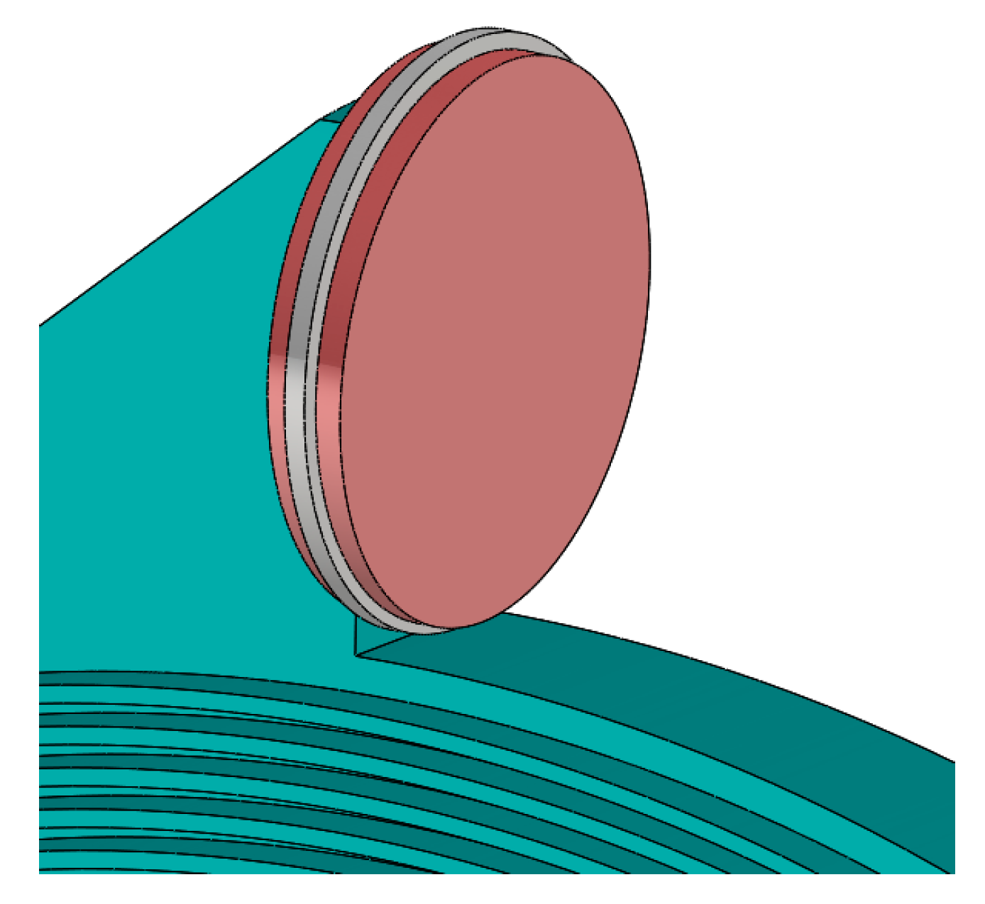
- One-sided straight labyrinth seal (Figure 5a) where all teeth are located on the rotating part (motion transfer arm). This kind of seal is very simple to manufacture and very cheap because conventional materials may be used for its construction. The first designs of such labyrinths used large chambers between two neighbouring teeth. Moreover, relatively long teeth can be easily damaged, destroying the chambers (or pockets) between them.
- Tooth interlocking labyrinth seal (Figure 5b). This seal usually employs a labyrinth with more teeth and a higher pressure drop. This kind of labyrinth sealing has not been investigated thoroughly by many researchers [28,29]. For this kind of labyrinth, the size of the teeth is also investigated, which practically modifies the size of the chamber between the teeth. The following teeth dimensions are investigated:
- 3 mm at the teeth basis and 2 mm at their edge
- 2 mm at the teeth basis and 1 mm at their edge
- 1 mm at the teeth basis and 1 mm at their edge
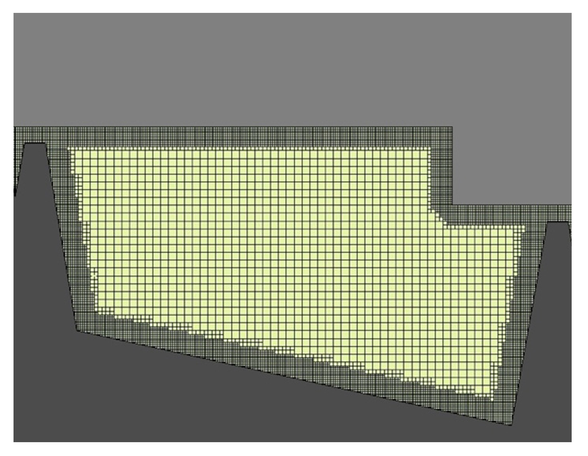
Mesh Description
CFD Model Setup
2.2.2. Compression Chamber’s Design
Simulation Model Setup
Model Optimization
3. Results and Discussion
3.1. Sealing Optimization
3.2. Compression Chamber Configuration
4. Conclusions
Supplementary Materials
Author Contributions
Funding
Acknowledgments
Conflicts of Interest
References
- European Commission. Regulation (EU) 2019/631 of the European Parliament and of the Council of 17 April 2019, Setting CO2 Emission Performance Standards for New Passenger Cars and for New Light Commercial Vehicles, and Repealing REGULATIONS (EC) No 443/2009 and (EU) No 510/2011; European Commission: Brussels, Belgium, 2019. [Google Scholar]
- Federal Register, Department of Transportation. 2017 and Later Model Year Light-Duty Vehicle Greenhouse Gas Emissions and Corporate Average Fuel Economy Standards; Final Rule; U.S. Environmental Protection Agency: Washington, DC, USA, 2012; Volume 77, pp. 62623–63200.
- European Commission. Regulation (EU) 2019/1242 of the European Parliament and of the Council of 20 June 2019, Setting CO2 Emission Performance Standards for New Heavy-Duty Vehicles and Amending Regulations (EC) No 595/2009 and (EU) 2018/956 of the European Parliament and of the Council and Council Directive 96/53/EC; European Commission: Brussels, Belgium, 2019. [Google Scholar]
- Statharas, S.; Moysoglou, Y.; Siskos, P.; Zazias, G.; Capros, P. Factors Influencing Electric Vehicle Penetration in the EU by 2030: A Model-Based Policy Assessment. Energies 2019, 12, 2739. [Google Scholar]
- Yugo, M.; Soler, A. A Look into the Role of e-Fuels in the Transport System in Europe (2030–2050) (Literature Review). Available online: https://www.concawe.eu/wp-content/uploads/E-fuels-article.pdf (accessed on 1 April 2020).
- Ash, N.; Sikora, I.; Richelle, B. Electrofuels for Shipping: How Synthetic Fuels from Renewable Electricity Could Unlock Sustainable Investment in Countries Like Chile; Environmental Defense Fund: London, UK, 2019. [Google Scholar]
- ERTRAC (European Road Transport Research Advisory Council) Working Group: Energy and Environment. Future Light and Heavy Duty ICE Powertrain Technologies; ERTRAC: Brussels, Belgium, 2016. [Google Scholar]
- O’Connor, J.; Borz, M.; Ruth, D.; Han, J.; Paul, C.; Imren, A.; Haworth, D.; Martin, J.; Boehman, A.; Li, J.; et al. Optimization of an Advanced Combustion Strategy Towards 55% BTE for the Volvo SuperTruck Program. SAE Int. J. Engines 2017, 10, 1217–1227. [Google Scholar] [CrossRef]
- Kocher, L. Final Scientific/Technical Report: Enabling Technologies for Heavy-Duty Vehicles—Cummins 55BTE. Available online: https://www.osti.gov/servlets/purl/1474075 (accessed on 1 March 2020). [CrossRef]
- Castiglione, T.; Morrone, P.; Falbo, L.; Perrone, D.; Bova, S. Application of a Model-Based Controller for Improving Internal Combustion Engines Fuel Economy. Energies 2020, 13, 1148. [Google Scholar] [CrossRef] [Green Version]
- Shkolnik, N.; Shknolnik, S. Rotary High Efficiency Hybrid Cycle Engine; SAE Technical Paper 2008-01-2448; SAE International: Warrendale, PA, USA, 2008. [Google Scholar]
- Spreitzer, J.; Zahradnik, F.; Geringer, B. Implementation of a Rotary Engine (Wankel Engine) in a CFD Simulation Tool with Special Emphasis on Combustion and Flow Phenomena; SAE Technical Paper 2015-01-0382; SAE International: Warrendale, PA, USA, 2015. [Google Scholar]
- Kutlar, O.A.; Malkaz, F. Two-Stroke Wankel Type Rotary Engine: A New Approach for Higher Power Density. Energies 2019, 12, 4096. [Google Scholar] [CrossRef] [Green Version]
- Li, Z.; Shih, T.I.P.; Schock, H.J.; Willis, E.A. A Numerical Study on the Effects of Apex Seal Leakage on Wankel; SAE Technical Papers; SAE International: Warrendale, PA, USA, 1991. [Google Scholar]
- Gasim, M.M.; Noor, M.M.; Kadirgama, K. Theoretical Torque Comparison between Revetec Engine and Conventional Internal Combustion Engine. In Proceedings of the 1st National Conference in Mechanical Engineering Research and Postgraduate Students (NCMER 2010), Universiti Malaysia Pahang, Kuantan, Malaysia, 26–27 May 2010. [Google Scholar]
- Meldolesi, R.; Badain, N. Scuderi Split Cycle Engine: Air Hybrid Vehicle Powertrain Simulation Study; SAE Technical Paper 2012-01-1013; SAE International: Warrendale, PA, USA, 2012. [Google Scholar]
- Ashley, S. New Axial-Piston Engine Aimed at Range Extenders, Military Applications. Available online: https://www.sae.org/news/2014/08/new-axial-piston-engine-aimed-at-range-extenders-military-applications (accessed on 1 April 2020).
- Zima, S.; Ficht, R. Ungewöhnliche Motoren (in German); Vogel Business Media: Würzburg, Germany, 2010. [Google Scholar]
- Zhang, Y.; Zuo, Z.; Liu, J. Numerical Analysis on Combustion Characteristic of Leaf Spring Rotary Engine. Energies 2015, 8, 8086. [Google Scholar] [CrossRef] [Green Version]
- Savvakis, S.; Gkoutzamanis, V.; Samaras, Z. Description of a Novel Concentric Rotary Engine; SAE Technical Paper 2018-01-0365; SAE International: Warrendale, PA, USA, 2018. [Google Scholar] [CrossRef]
- Ferguson, C.R.; Kirkpatrick, A.T. Internal Combustion Engines—Applied Thermosciences; John Wiley & Sons: Hoboken, NJ, USA, 2001. [Google Scholar]
- Blog, T. 8 September 2008. Available online: http://pressroom.toyota.com/article_print.cfm?article_id=2722 (accessed on 1 April 2020).
- Heywood, J.B. Internal Combustion Engine Fundamentals; McGraw-Hill: New York, NY, USA, 1988. [Google Scholar]
- Kobayashi, H.; Sugihara, H.; Yoshida, H.; Kawase, N.; Akimoto, Y. Effect of Top Rings on Piston Slap Noise; SAE Technical Paper 952236; SAE International: Warrendale, PA, USA, 1995. [Google Scholar] [CrossRef]
- Gkoutzamanis, V.G.; Savvakis, S.; Kalfas, A.I. Numerical Simulation of a Novel Rotary Engine Compared to Conventional Reciprocating Engine Cycle. In Proceedings of the GPPS Conference 2017, Shanghai, China, 30 October–1 November 2017. [Google Scholar]
- Zhang, M.; Yang, J.; Xu, W.; Xia, Y. Leakage and rotordynamic performance of a mixed labyrinth seal compared with that of a staggered labyrinth seal. J. Mech. Sci. Technol. 2017, 31, 2261–2277. [Google Scholar] [CrossRef]
- Kang, Y.; Kim, T.S.; Kang, S.Y.; Moon, H.K. Aerodynamic Performance of Stepped Labyrinth Seals for Gas Turbine Applications. In Proceedings of the ASME Turbo Expo 2010: Power for Land, Sea, and Air. Volume 4: Heat Transfer, Parts A and B, Glasgow, UK, 14–18 June 2010; pp. 1191–1199. [Google Scholar]
- Memmott, E.A. Empirical Estimation of a Load Related Cross-Coupled Stiffness and the Lateral Stability of Centrifugal Compressors. In Proceedings of the 18th Machinery Dynamics Seminar, Canadian Machinery Vibration Association, Halifax, NS, Canada, 26–28 April 2000. [Google Scholar]
- Gao, R.; Kirk, G. CFD Study on Stepped and Drum Balance Labyrinth Seal. Tribol. Trans. 2013, 56, 663–671. [Google Scholar] [CrossRef]
- Kim, T.S.; Cha, K.S. Comparative analysis of the influence of labyrinth seal configuration on leakage behavior. J. Mech. Sci. Technol. 2009, 23, 2830–2838. [Google Scholar] [CrossRef]
- Eser, D.; Dereli, Y. Comparisons of Rotordynamic Coefficients in Stepped Labyrinth Seals by Using Colebrook-White Friction Factor Model. Meccanica 2007, 42, 177–186. [Google Scholar] [CrossRef]
- Stoker, H.L. Determining and Improving Labyrinth Seal Performance in Current and Advanced High Performance Gas Turbines; AGARD–CP–237 (AGARD–AR–123), Paper 13; AGARD: London, UK, August 1978. [Google Scholar]
- Waschka, W.; Wittig, S.; Kim, S. Influence of high rotational speeds on the heat transfer and discharge coefficients in labyrinth seals. J. Turbomach. 1992, 114, 462–468. [Google Scholar] [CrossRef]
- Ha, T. Rotordynamic Analysis for Stepped-Labyrinth Gas Seals Using Moody’s Friction-Factor Model. J. Mech. Sci. Technol. 2001, 15, 1217–1225. [Google Scholar] [CrossRef]
- Yuecel, U. Calculation of Leakage and Dynamic Coefficients of Stepped Labyrinth Gas Seals. Appl. Math. Comput. 2004, 152, 521–533. [Google Scholar] [CrossRef]
- Subramaniana, S.; Sekhara, A. Rotordynamic characterization of rotating labyrinth gas turbine seals with radial growth_Combined centrifugal and thermal effects. Int. J. Mech. Sci. 2017, 123, 1–19. [Google Scholar] [CrossRef]
- Mirzamoghadam, A.V.; Xiao, Z. Flow and heat transfer in an industrial rotor-stator rim sealing cavity. J. Eng. Gas Turbines Power 2002, 124, 125–132. [Google Scholar] [CrossRef]
- Thorat, M.; Childs, D. Predicted rotordynamic behavior of a labyrinth seal as rotor surface velocity approaches mach1. ASME J. Eng. Gas Turbines Power 2010, 132, 112504. [Google Scholar] [CrossRef]
- Li, Z.; Li, J.; Feng, Z. Numerical comparisons of rotordynamic characteristics for three types of labyrinth gas seals with inlet preswirl. IMechE Part A J. Power Energy 2016. [Google Scholar] [CrossRef]
- Converge Science, Converge CFD 2.4 Manual; CONVERGE CFD: Detroit, MI, USA, 2018.
- Savvakis, S. Computational Investigation of a Novel Concentric Rotary Engine. Ph.D. Thesis, Aristotle University of Thessaloniki, Thessaloniki, Greece, 2011. [Google Scholar]
- Schramm, V.; Denecke, J.; Kim, S.; Wittig, S. Shape Optimization of a Labyrinth Seal Applying the Simulated Annealing Method. Int. J. Rotating Mach. 2004, 10, 365–371. [Google Scholar] [CrossRef]


| Setup | Selected options |
|---|---|
| Solver Convergent Criterion | Navier-Stokes Pressure-Based PISO |
| 3D | Periodic Boundary/Sector (pie shape) |
| Flow Assumption | Steady, ideal gas compressible, turbulent |
| Models | Time based, SST k-ω |
| Materials | Air (ideal gas) |
| Operating Pressure (bar) | 0 |
| Pressure-inlet (bar) | 50 |
| Inlet Temperature (K) | 700 |
| Pressure-outlet (bar) | 2 |
| Outlet Temperature (K) | 450 |
| Wall properties | Adiabatic, absolute roughness=0, no-slip |
| Solution Methods Scheme | Transient |
| Spatial Discretization | Second Order Upwind |
| Solution Initialization | Hybrid |
| Convergence criterion | PISO tolerance 10−6 |
| Configuration | CFD | Isentropic process | ||
|---|---|---|---|---|
| Peak p (bar) | Peak T (K) | Peak p (bar) | Peak T (K) | |
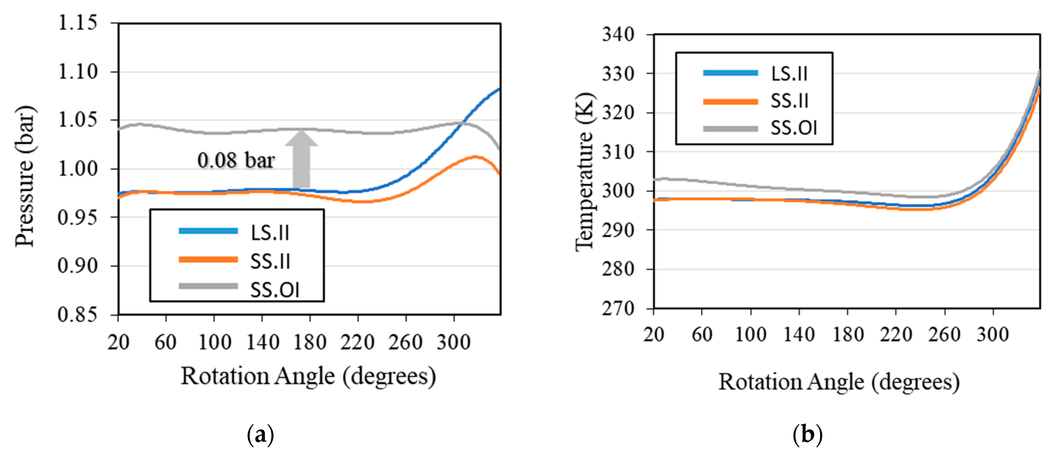
| LS.II | 23.3 | 587 | 28.9 | 775 |
| SS.II | 25.6 | 617 | 28.9 | 775 |
| SS.OI | 26.9 | 614 | 28.9 | 775 |
© 2020 by the authors. Licensee MDPI, Basel, Switzerland. This article is an open access article distributed under the terms and conditions of the Creative Commons Attribution (CC BY) license (http://creativecommons.org/licenses/by/4.0/).
Share and Cite
Savvakis, S.; Mertzis, D.; Nassiopoulos, E.; Samaras, Z. A Design of the Compression Chamber and Optimization of the Sealing of a Novel Rotary Internal Combustion Engine Using CFD. Energies 2020, 13, 2362. https://doi.org/10.3390/en13092362
Savvakis S, Mertzis D, Nassiopoulos E, Samaras Z. A Design of the Compression Chamber and Optimization of the Sealing of a Novel Rotary Internal Combustion Engine Using CFD. Energies. 2020; 13(9):2362. https://doi.org/10.3390/en13092362
Chicago/Turabian StyleSavvakis, Savvas, Dimitrios Mertzis, Elias Nassiopoulos, and Zissis Samaras. 2020. "A Design of the Compression Chamber and Optimization of the Sealing of a Novel Rotary Internal Combustion Engine Using CFD" Energies 13, no. 9: 2362. https://doi.org/10.3390/en13092362