Article

Study on the Impact Pressure of Swirling-Round Supercritical CO2 Jet Flow and Its Influencing Factors

1
Unconventional Petroleum Research Institute, China University of Petroleum, Beijing 102200, China
2
Engineering & Design Institute of CPOE, Offshore Engineering Company Ltd., CNPC, Beijing 100028, China
3
National Computer Network Emergency Response Technical Team, Coordination Center of China, Beijing 100029, China
4
College of Petroleum Engineering, China University of Petroleum, Beijing 102200, China
*
Author to whom correspondence should be addressed.
Energies 2021, 14(1), 106; https://doi.org/10.3390/en14010106
Submission received: 16 November 2020 / Revised: 17 December 2020 / Accepted: 24 December 2020 / Published: 28 December 2020
(This article belongs to the Section B: Energy and Environment)

Abstract

:
Supercritical carbon dioxide (SC-CO2) jet is capable of decreasing the threshold pressure of rock breakage and mitigating formation damage, owing to its low viscosity, high diffusivity, and extremely-low surface tension. The swirling-round jet holds the advantages of both a swirling jet and a round jet. Therefore, the comprehensive technique, swirling-round SC-CO2 (SR-SC-CO2) jet, is expected to substantially enhance rock-breaking efficiency. However, theoretical analysis of the flow field characteristics of SR-SC-CO2 has not been reported yet. This work aims to lay a theoretical foundation for employing SR-SC-CO2 in drilling and fracturing. The flow field is simulated using Naiver-Stokes equations and the RNG k-ε turbulence model. Sensitivity analysis, regarding pressure drop of the nozzle, confining pressure, fluid temperature, jetting distance, the diameter of the nozzle’s central hole, and grooving area, are performed. We show that the combined swirling-round SC-CO2 jet flow could maintain a relatively larger axial as well as tangential velocity compared to a single approach of swirling jet or round jet, enabling one to acquire a deeper oillet and expand the perforation area effectively. The simulation results substantiate the enormous potential of SR-SC-CO2 in improving rock-breaking efficiency and clarify the influence of relevant parameters on the impact pressure of the jet flow.

1. Introduction

With the development of petroleum exploration and exploitation toward a deeper formation, the quantity of deep and ultra-deep wells is ever-increasing [1,2,3]. One critical issue of successful deep well drilling is to enhance the rate of penetration (ROP) and lower drilling costs [4]. High-pressure water (HPW) jet has played a crucial role in deep-well exploitation. However, several problems of HPW, including high water consumption, clay swelling, groundwater contamination, treatment of flow-back fluid, and high threshold pressure of rock breaking, remain to be solved [5,6,7,8,9,10,11,12]. By improving the jet pressure, modifying nozzle structures, or introducing new fluid, a series of novel jet technologies have been proposed.
Li and Shen [13] put forward a dual-jet concept that combines a swirling jet and a round jet. Buckman et al. [14] designed the swirling-round jet bit to effectively eliminate the central low-speed zone and the convex plate of the swirling jet. The swirling-round jet is a mixed jet flow of the swirling jet passing through the swirling groove of the impeller and the round jet flowing through the impeller’s central channel. The rock-breaking effect and flow field characteristics of the swirling-round water (SRW) jet have been extensively investigated [15,16]. It has been concluded that SRW synthesizes the greater rock-breaking depth of the round jet and larger rock-breaking area of the swirling jet, enabling one to decrease the threshold pressure of rock breakage and sharply increase rock-breaking efficiency.
Supercritical CO2 has been recognized as a successful candidate for drilling and fracturing fluid, given its low viscosity, high diffusivity, and extremely-low surface tension [17,18,19,20,21,22,23,24]. Those unique physicochemical properties provide significant advantages to the SC-CO2 jet. Firstly, the threshold pressure of rock breaking of the SC-CO2 jet is far below that of the water jet [21,22]. Secondly, considering the stronger adsorption capability of CO2 onto the rock surface [25,26,27,28], CO2 is expected to replace initially adsorbed shale-gas and coal bed methane in a matrix, enhancing hydrocarbon recovery [29,30,31,32,33,34,35]. Furthermore, clay swelling and formation damage caused by water injection are mitigated to the maximum extent [17,18]. Experimental results suggested that comparing with the water jet, SC-CO2 jet is more efficient in rock-breaking due to its higher rock-breaking speed and lower threshold pressure. Kolle [17] reported that the ROP of SC-CO2 jet in the Mancos shale is 3.3 times as high as the water jet, while the specific energy of rock breakage is only 20% of the water jet. Kolle and Marvin [36] substantiated the feasibility of using SC-CO2 as drilling fluid by conducting field trials of SC-CO2 assisted drilling. Tian et al. [16] investigated the rock-breaking effect of the swirling SC-CO2 jet. He et al. [37] numerically studied the flow field of the SC-CO2 abrasive jet and clarified the influence of confining pressure, fluid temperature, and jetting distance on rock breakage. Cheng et al. [38] concluded that the SC-CO2 jet exhibits higher flow speed, longer core zone, and stronger capability of enhancing pressurizing effect if compared with the water jet.
Tian et al. [39] experimentally studied the rock-breaking efficiency of swirling-round SC-CO2 jet. Their results suggested that the radial rock-breaking capability of swirling jet can be perfectly combined with the axial rock-breaking capacity of round jet. Figure 1 shows the rock-breaking effects of the swirling jet, the round jet, and their combination. The stronger oillet-enlarging ability and greater perforation depth of the swirling-round jet can be observed. The swirling-round SC-CO2 jet allows us to find a balance between perforating depth and area, and thus the rock-breaking efficiency is enhanced.
In this paper, we present numerical simulation on the rock-breaking efficiency and impact pressure of the swirling-round SC-CO2 jet. Navier-Stokes equations and the RNG k-ε turbulence model are used to simulate the three-dimensional flow field.

2. Numerical Simulation

In this section, we demonstrate the geometric model and meshing (Section 2.1), governing equations (Section 2.2), and structure parameter setting (Section 2.3).

2.1. Geometric Model and Meshing

Figure 2a demonstrates the three-dimensional geometric model for the simulation of the swirling-round SC-CO2 jet flow field. The cross-section areas of the swirling-round jet nozzle are 4 mm2, and the central hole’s diameter of a spiral impeller is 2 mm. A cylinder of 30 mm in diameter and 12 mm in height is designed as the impactor at the nozzle outlet. The established model incorporates a swirling-round jet (including an inlet section, rotary section, mixing section, convergent section, outlet section, and lengthened section) and impact zone of jet flow. When a low-speed fluid enters the nozzle, a part of fluid flows through the spiral impeller, forming a swirling jet, while the other part of fluid flows through the central hole, generating a round-straight jet. The swirling and round-straight jet flows are thoroughly blended in the mixing chamber, giving rise to a mixed flow of a low speed. The mixed flow passes through the nozzle outlet and the lengthened section, then the created high-speed swirling-round jet flow impacts the downstream surface and eventually flows out the field. The pressure at the nozzle inlet is set as the inlet boundary value of pressure, and the ambient pressure determines the outlet-boundary pressure at the nozzle outlet. The central channel, convergent section, outlet section, and lengthened section of the nozzle and the impact zone of dual-jet flow are partitioned with a structured grid. In contrast, an unstructured grid is used for the nozzle entrance, helical channel, and mixing section. Figure 2b shows the amplification of meshing at the rotating impeller and central channel.

2.2. Governing Equations

The swirling-round SC-CO2 jet flow obeys the conservation laws of mass, momentum, and energy. The RNG k-ε model is used for the turbulence closure, given that the SC-CO2 jet is a turbulent flow. The complete governing equations are given as follows.

2.2.1. Continuity Equation

The equation for continuity equation, or conservation of mass, can be described by [40]:
ρ t + x i ( ρ u i ) = 0 ,
where ρ is density, kg/m3; ui denotes the ith component of time-averaged velocity, m/s; t is time, s; xi represents the ith coordinates, m. i = 1, 2, 3.

2.2.2. Momentum Conservation Equation

Conservation of momentum in each direction is written as [40]:
ρ t ( ρ u i ) + x j ( ρ u i u j ) = p x i + x j [ μ ( u i x j + u j x i 2 3 δ i j u l x l ) ] + x j ( ρ u i u j ¯ ) ,
where μ is molecular viscosity, Pa∙s; p is static pressure, Pa; σij is the Kronecker delta function; Reynolds stresses, ρ u i u j ¯ representing the effect of turbulence, is given by:
ρ u i u j ¯ = μ t ( u i x j + u j x i ) 2 3 ( ρ k + μ t u k x k ) δ i j ,
where k is the turbulent kinetic energy per unit mass, J/kg; μt is turbulent viscosity, m2/s, calculated by μ t = ρ c μ k 2 / ε ; ε is dissipation rate, m2/s3; cμ is a constant with a default value of 0.09.

2.2.3. Energy Conservation Equation

Conservation of energy is given as [41,42]:
t ( ρ E ) + x i [ u i ( ρ E + p ) ] = x j [ ( k h + c p μ t Pr t ) T x j + u i ( τ i j ) e f f ] + S h ,
where cp is specific heat, J/kg∙K; T is temperature, K; E is the total energy, J; kh is thermal conductivity, W/m∙K; Sh denotes the heat of chemical reaction or any other volumetric heat sources; Prt is the turbulent Prandtl number for energy; ij)eff is the deviatoric stress tensor, defined as:
( τ i j ) e f f = μ e f f ( u i x j + u j x i ) 2 3 μ e f f u k x k δ i j .
The effective viscosity μeff is given by:
μ e f f = μ + μ t .

2.2.4. RNG k-ε Equations

The RNG k-ε equations are given by [42,43]:
( ρ k ) t + ( ρ u i k ) x i = x j [ α k μ e f f k x j ] + G k + G b ρ ε Y M ,
( ρ ε ) t + ( ρ u i ε ) x i = x j [ α ε μ e f f ε x j ] + C 1 ε ε k ( G k + C 3 ε G b ) C 2 ε ρ ε 2 k R ε s
where αk and αε are the inverse effective Prandtl numbers for k and ε, respectively, with both given by 1.39; C3ε is the buoyancy coefficient, equal to one if the flow direction is perpendicular to the direction of gravity and zero if the flow direction is parallel to the direction of gravity; C1ε and C2ε are constants, given by 1.42 and 1.68, respectively.
Gk is the mean velocity gradient induced turbulence kinetic energy, determined by:
G k = μ t ( u i x j + u j x i ) u i x j .
Gb is the buoyancy induced turbulence kinetic energy, determined by:
G b = β g i μ t Pr t T x i ,
where gi is the component of the gravitational vector in the ith direction, m/s2; β is the coefficient of thermal expansion, K−1; YM denotes the contribution of fluctuating dilatation to the overall dissipation rate, determined by
Y M = 2 ρ ε M t 2 ,
where Mt is the turbulent Mach number, defined as
M t = k a 2 ,
where a is the sound speed, m/s.
Rε is given by:
R ε = c μ ρ η 3 ( 1 η / η 0 ) 1 + β η 3 ε 2 k ,
where η = Sk/ε, η0 = 4.38, β = 0.012.

2.2.5. Boundary Conditions

Inlet Boundary

The nozzle inlet serves as the inlet of the geometrical model with the pressure inlet condition (Figure 2a). The inlet pressure and fluid temperature are given by 30 MPa and 400 K, respectively.

Outlet Boundary

The outlet of the geometrical model with the pressure outlet condition is defined at the jet nozzle exit (Figure 2a). The outlet pressure and fluid temperature are given by 40 MPa and 400 K, respectively.

Wall Boundary Conditions

(i)
Wall boundary of u
The law-of-the-wall for mean velocity yields [42]:
u * = 1 κ ln ( E m y * ) ,
where κ is the von Karman constant, set as 0.4187; Em is an empirical constant, given by 9.793; y* is the dimensionless distance from the wall, defined by ρ k p 1 / 2 c μ 1 / 4 y p μ , and u* is dimensionless velocity, denoted by k p 1 / 2 c μ 1 / 4 u p τ w / ρ . kp is turbulence kinetic energy at the near-wall node P, J/kg; yp is the distance from point P to the wall, m; up is the mean velocity of the fluid at node P, m/s; cμ is a constant with a default value of 0.09; τw is the wall-shear stress, Pa, determined by:
τ w = ρ c μ 1 / 4 k p 1 / 2 u p / u * ,
y* varies from 11.225 to 300 to guarantee the validity of the logarithmic distribution of velocity. When y* is less than 11.225 at the wall-adjacent cells, the laminar stress-strain relationship is employed, i.e., u * = y * .
(ii)
wall boundary of T
The wall boundary of T is determined by:
T * = { Pr y * + 1 2 ρ Pr c μ 1 / 4 k p 1 / 2 q u p 2                                                                          ( y * < y T * ) Pr t [ 1 κ ln ( E m y * ) + P e ] + 1 2 ρ c μ 1 / 4 k p 1 / 2 q [ Pr t u p 2 + ( Pr Pr t ) u c 2 ]             ( y * y T * ) ,
where Pr is the Prandtl number; uc is the average velocity magnitude at y * = y T * , m/s; y T * represents the non-dimensional thermal sublayer thickness. q is the density of heat flux at the wall, W/m2; Pe is given by Jayatilleke (1969) for a smooth wall:
P e = 9.24 [ ( Pr Pr t ) 3 / 4 1 ] [ 1 + 0.28 e 0.007 Pr / Pr t ] .
(iii)
wall boundary of k and ε
In the k-ε model, the k equation is solved in the whole domain incorporating the wall-adjacent cells. The boundary condition for k imposed on the wall is:
k n = 0 ,
where n is the local coordinate normal to the wall, m.
The wall boundary of the generation term of turbulent kinetic energy Gk and dissipation rate ε are determined from the local equilibrium assumption:
G k τ w u y = τ w 2 κ ρ k p 1 / 2 y p ,
ε P = c μ 3 / 4 k p 3 / 2 κ y p .

2.3. Structure Parameter Setting

Structure parameters of the nozzle used in the three-dimensional flow field simulation of the swirling-round SC-CO2 jet are summarized in Table 1.

2.4. Simulation Procedure

ANSYS Fluent 14.0 is used for our simulation. The finite volume method is selected to discrete the computational domain, generating small volume units on which the SIMPLE algorithm is performed [44]. The velocity field corresponding to the initial guess of the pressure field is obtained by solving the momentum equation. The corrected value of pressure is acquired from the continuity equation, resulting in an updated pressure and velocity field. The updated pressure field is set as a new guess for the pressure field if the calculated results are not convergent, and the calculation process is repeated until convergence.

3. Results and Discussion

In this section, we discuss the obtained simulation results. Section 3.1 presents the flow field characteristics of the swirling-round SC-CO2 jet. Section 3.2 performs sensitivity analysis of critical parameters, including the pressure drop of the nozzle, confining pressure, jet flow temperature, jetting distance, the diameter of the nozzle’s central hole, and the grooving area of the nozzle.

3.1. Flow Field Simulation

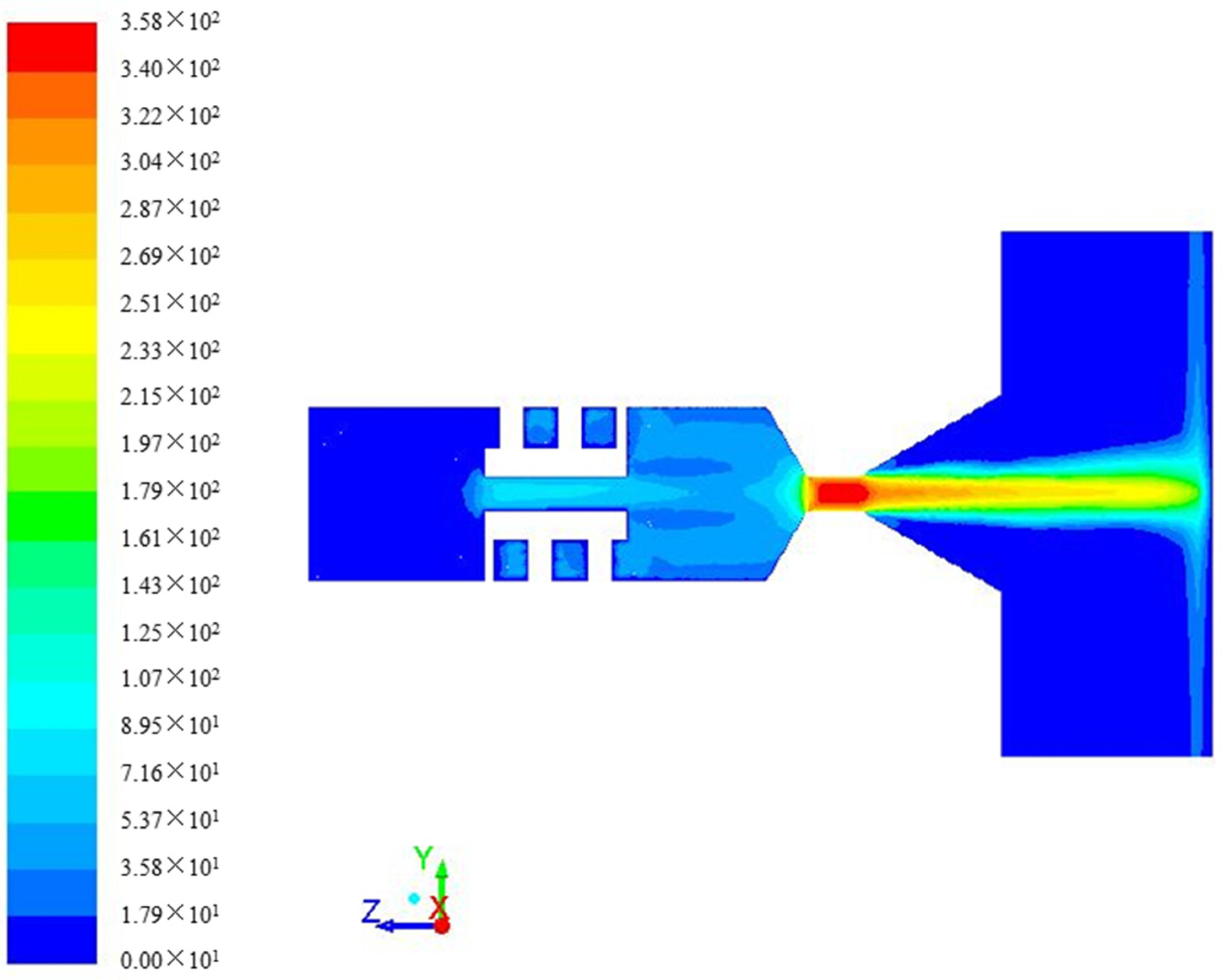
The supercritical CO2 enters the nozzle and is split into two jets. One of the jets accesses the straight channel, forming a round jet, while the other one enters the rotating channel, generating a swirling jet. The round jet and swirling jet are fully mixed in the mixing section, giving rise to a swirling-round SC-CO2 jet flow, which hits the wall after flowing through the nozzle outlet and lengthened section. Figure 3 and Figure 4 reveal the flow field simulation results. When the SC-CO2 flow through the convergent section of the nozzle, fluid pressure decreases, and flow velocity sharply rises, resulting in the swirling-round SC-CO2 jet flow that hits the wall on the right side. Not surprisingly, the hitting speed reached its maximum on the jet axis, while getting lower to both sides.
The axial and tangential velocities of the mixed jet are investigated to unveil the jet energy’s attenuation law.
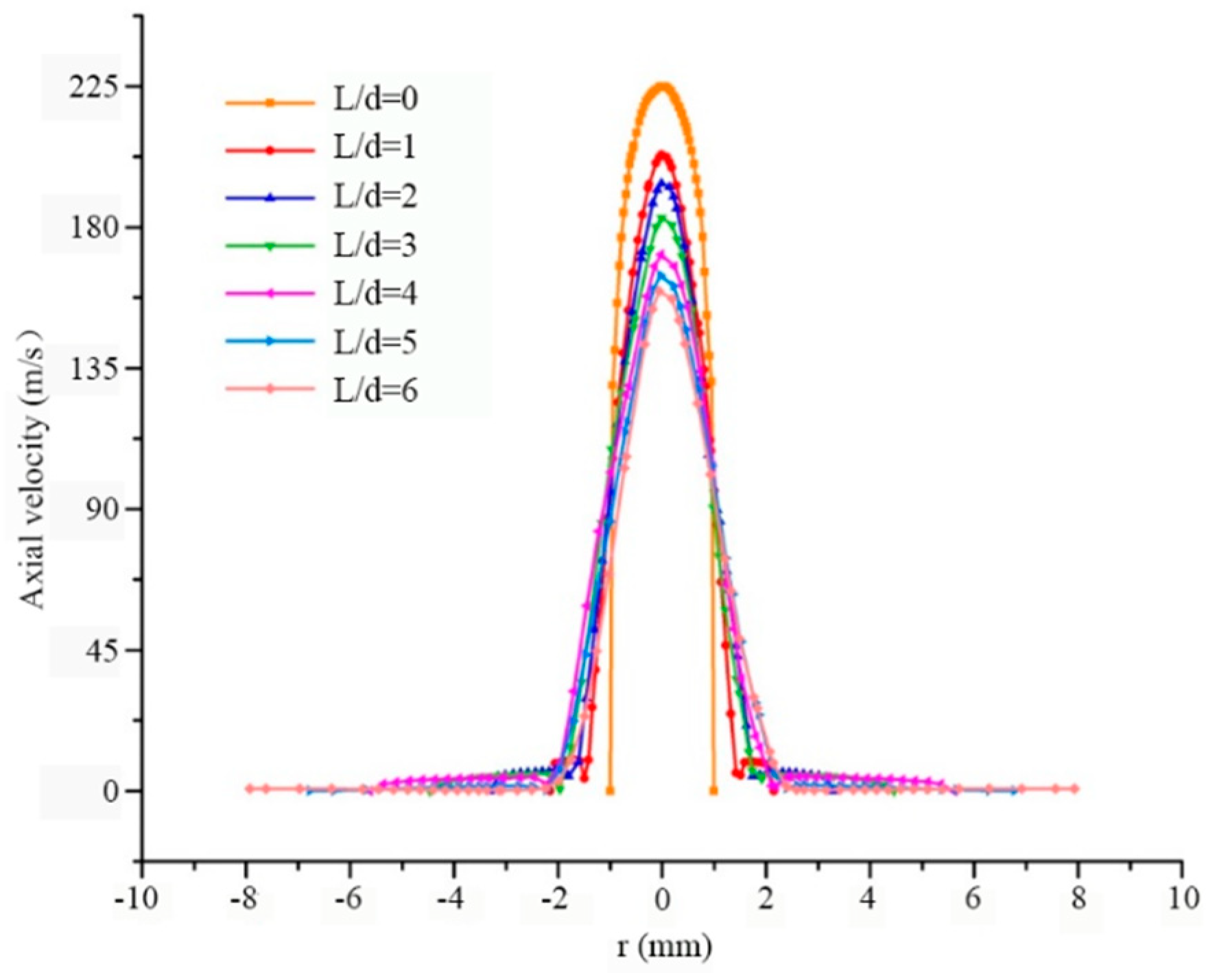
Figure 5 exhibits the distribution and evolution of axial velocity. The axial radius r is given as the abscissa. Sensitivity analysis is performed in regard to the dimensionless jetting distance, defined as the ratio of jetting distance L and the nozzle’s outlet diameter d. It is shown that the flow speed reaches its maximum at the central line, demonstrating more concentrated energy if L/d is zero. In contrast, energy drops sharply in the radial direction. This leads to a more substantial jet impact and a certain depth in perforating. When ejecting fluid of high speed, the entrainment effect of a swirling jet favors driving the flow of surrounding fluid and exchanging energy, which attenuates the axial velocity of jet flow.
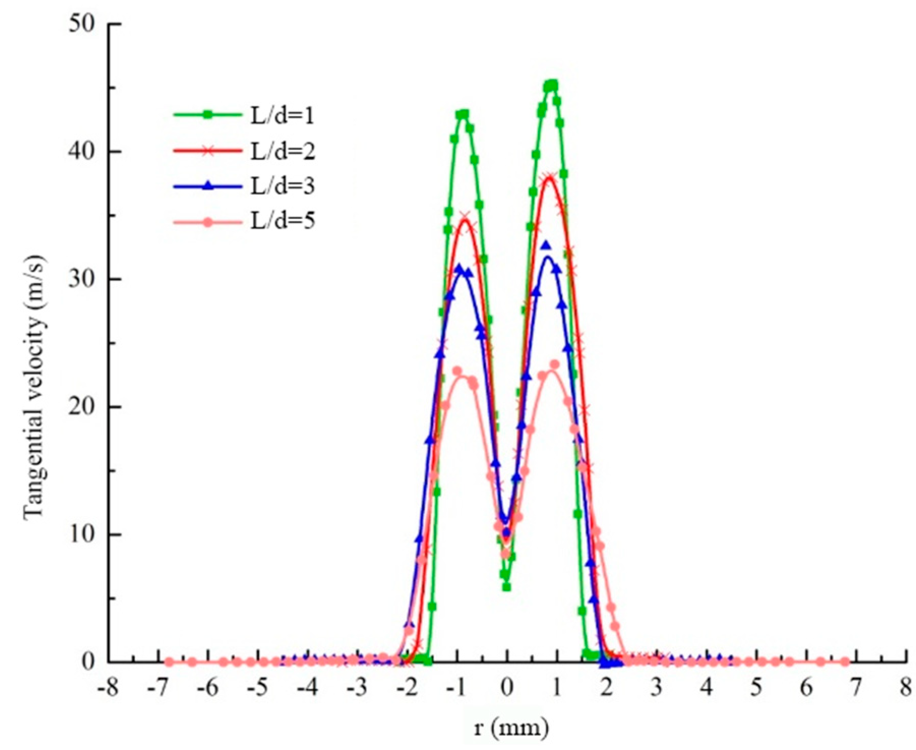
Figure 6 shows the distribution and evolution of tangential velocity. Given a particular jetting distance, the tangential velocity first increases and then decreases with an increasing jetting radius, reaching a maximum at a specific position away from the central line. Meanwhile, the action range of tangential velocity rises with the jetting distance, and the maximum value of tangential velocity declines with the jetting distance.
According to the distribution profiles shown in Figure 6, the tangential velocity at the central line reaches a local minimum far less than the values of the two maxima. However, in comparison, the axial velocity reaches its peak at the central line (Figure 5). Compared to a single approach, the combined swirling-round SC-CO2 jet flow could maintain a relatively larger axial as well as tangential velocity, enabling one to obtain a deeper oillet and expand the perforation area effectively, thus acquiring satisfactory rock breakage.
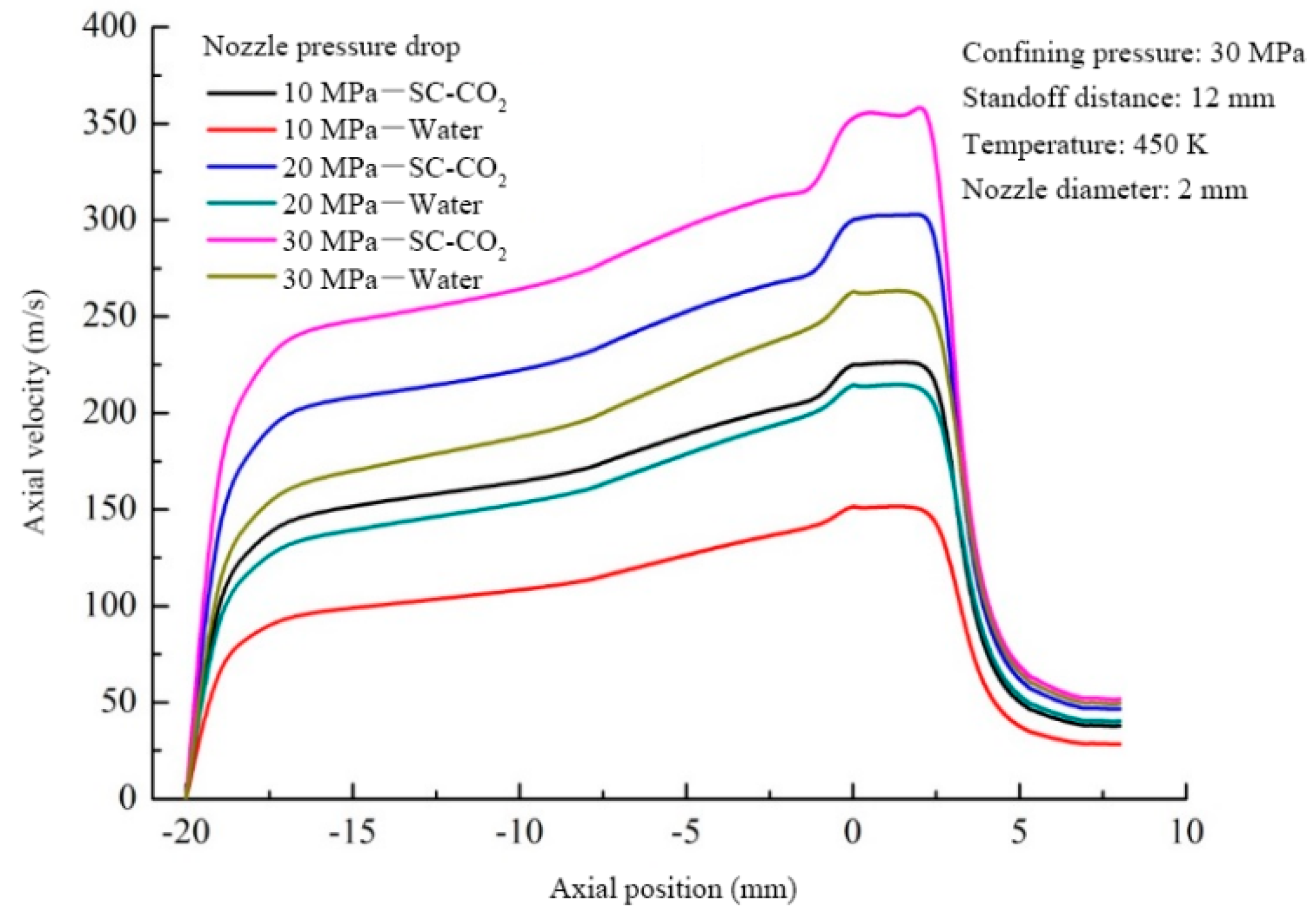
Figure 7 shows the axial velocity profiles of swirling-round SC-CO2 jet and water jet to compare their flow fields under the same parameters. Temperature and confining pressure are set as 450 K and 30 MPa, respectively. The wall surface is located at −20 mm of the axial coordinate, and 0 mm at the axial coordinate represents the nozzle’s outlet. As depicted in Figure 7, the maximum speeds of swirling-round SC-CO2 jet flow exhibit higher values compared with that of water jet under all pressure drops. For example, at the pressure drop of 30 MPa, the maximum speed of swirling-round SC-CO2 jet reaches 358 m/s, significantly higher than 263 m/s of the water jet. According to the Bernoulli equation, if the nozzle’s pressure drop maintains constant, then the SC-CO2 jet speed is higher than the water jet speed, due to the lower density of SC-CO2.

3.2. Parameter Analysis

3.2.1. Pressure Drop of the Nozzle

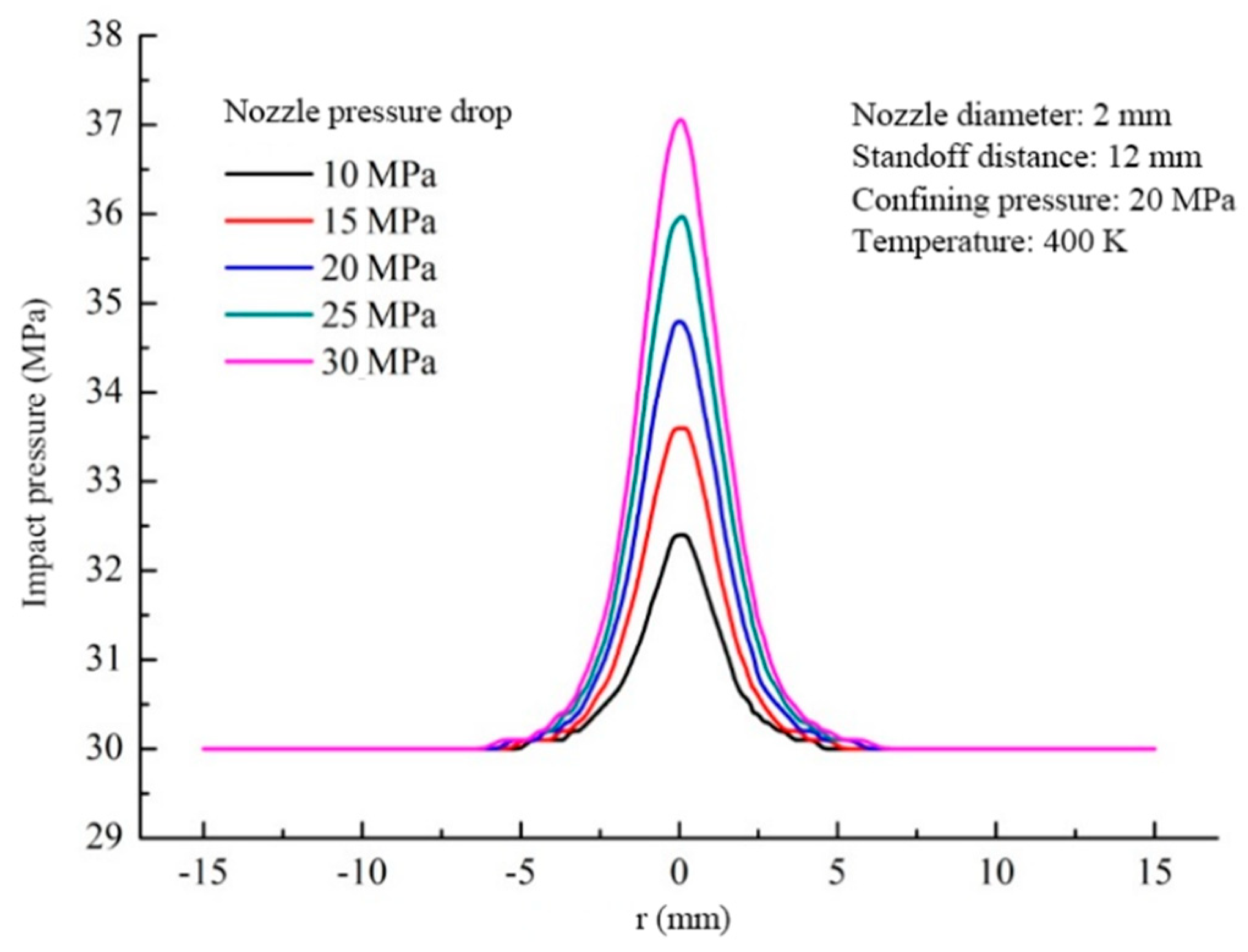
The nozzle’s pressure drop plays a significant role in determining the kinetic energy of jet flow, which directly influences the characteristics of the jet flow field. As the nozzle’s pressure drop increases, jet energy rises, improving the effect of rock breakage. Figure 8 depicts impact pressure under variant pressure drops of the nozzle. It is suggested that a higher pressure drop yields higher impact pressure. As a result, if the confining pressure remains invariant, the impact pressure increases with an increasing pressure drop. The pressure drop induced kinetic energy of jet flow rises as the nozzle’s pressure drop increases, and thus the impact pressure acting on the wall surface arisen from the jet flow. However, it should be noted that the impact range does not show a noticeable enlargement at a higher pressure drop.

3.2.2. Confining Pressure

The jet flow field can be affected by the downhole confining pressure. As shown in Figure 9, with increasing confining pressure, the pressure level of the wall exhibits an increase of the same magnitude. The strength and action range of impact pressure, however, is not influenced. Although the confining pressure allows determining the pressure level of the whole flow field, it shows no direct influence on jet kinetic energy and, thus, on the strength and action range of impact pressure.

3.2.3. Jet Flow Temperature

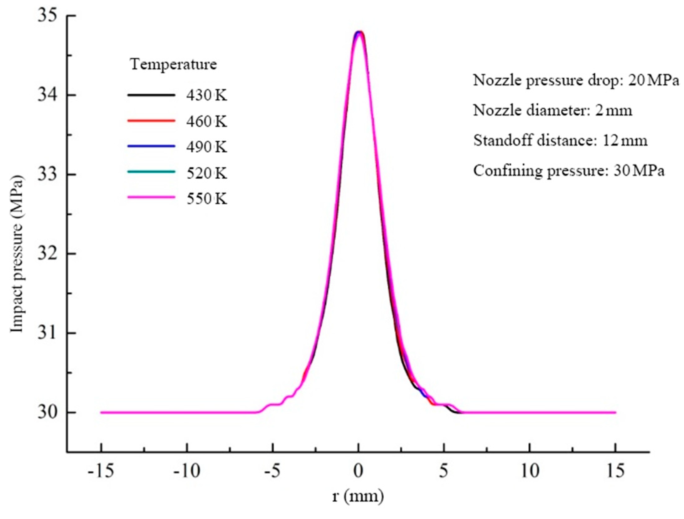
Figure 10 demonstrates fluid temperature effect on impact pressure. It is anticipated that temperature might influence the flow field by affecting the physical properties of a fluid. However, as shown in the figure, impact pressure and the action range of impact pressure are hardly influenced by temperature changes varying from 430 K to 550 K. It is worth noting that further variation of temperature demonstrates similar results (data not shown). Therefore, we conclude that fluid temperature can be ignored for engineering applications.

3.2.4. Jetting Distance

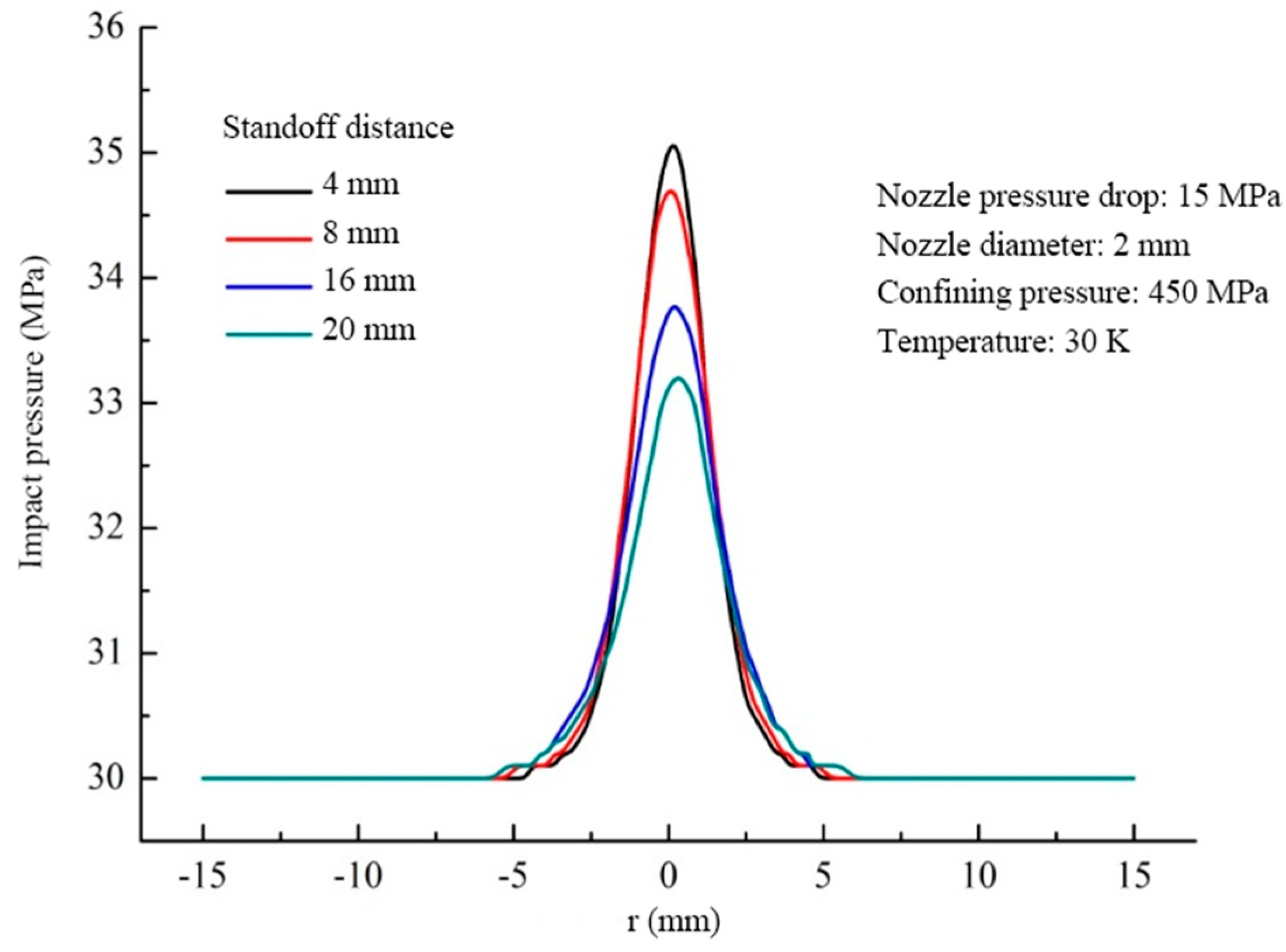
Jetting distance has a significant influence on rock breakage. Proper adjustment is essential to use jetting energy efficiently. As shown in Figure 11, impact pressure decreases with an increasing jetting distance. The impact range, however, expands slightly. When the jetting distance is small, the development of jet flow is inadequate and, therefore, the impact range is narrowed. Nevertheless, if the jetting distance is oversized, the high dissipation of jet energy might occur and lead to a slump of impact pressure. Accordingly, only if the jetting distance is appropriately selected can we achieve perfect impact pressure and action range of the SC-CO2 jet flow, thus acquiring the desired rock-breaking effect.

3.2.5. Diameter of the Nozzle’s Central Hole

Figure 12 shows the influence of the diameter of the nozzle’s central hole on impact pressure. 1 mm, 1.5 mm, 2 mm, and 2.5 mm are selected as typical values of the central hole’s diameter. It is shown that impact pressure and its action range increase with increasing hole size. If the nozzle’s pressure drop remains unchanged, larger hole diameter gives rise to the higher kinetic energy of round jet and thus the axial velocity and impact pressure acting on the wall. Therefore, increasing the nozzle’s pressure drop and using a nozzle of larger central hole size favor enhancing the impact pressure and action range of swirling-round SC-CO2 and improving the efficiency of rock breakage.

3.2.6. Grooving Area of the Nozzle

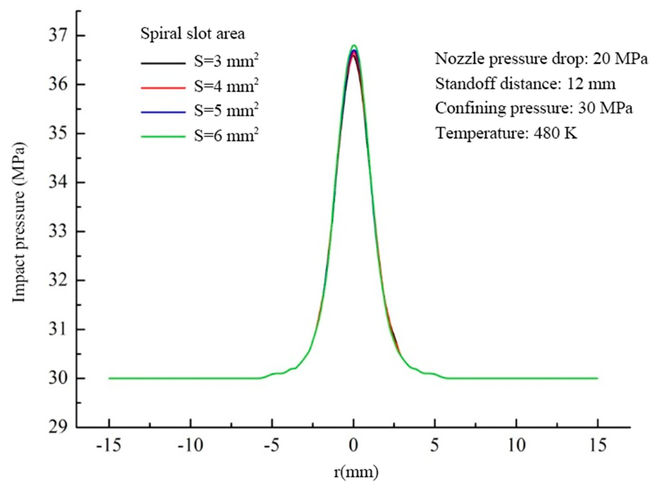
One may expect that the flow channel’s area can have a considerable effect on the generation of swirling jet. Figure 13 presents the influence of the grooving area (3 mm2, 4 mm2, 5 mm2, and 6 mm2) on swirling-round jet flow. As depicted, the larger grooving area of the impeller yields a slightly higher impact pressure. This could be explained by the fact that, rather than swirling jet, the round jet is the primary control of impact pressure. As a result, the grooving area could be neglected in practice due to its weak influence on the strength and impact range of the jet flow.

4. Conclusions

We present a synthetic simulation on the impact pressure of swirling-round supercritical CO2 jet flow. Sensitivity analysis of relevant parameters are performed. Our research allows drawing the following conclusions:
The swirling-round SC-CO2 jet exhibits a higher flow speed and a more substantial rock-breaking effect compared with the water jet flow, showing combined advantages of the round jet and swirling jet.
Compared to a single approach of swirling jet or round jet, the combined swirling-round SC-CO2 jet flow could maintain a relatively larger axial as well as tangential velocity, enabling one to obtain a deeper oillet and expand the perforation area effectively.
Higher pressure drop of the nozzle yields higher impact pressure. Moreover, the strength and action range of impact pressure also increase with the increasing diameter of the nozzle’s central hole. As a result, rock breakage could be improved by enlarging the nozzle’s pressure drop and central hole size.
As the jetting distance increases, the strength of impact pressure declines, while its action range expands. An appropriate jetting distance is essential to achieving perfect impact pressure and action range for swirling-round SC-CO2 jet flow, thus acquiring the desired rock-breaking effect.
Confining pressure, fluid temperature, and grooving area have a negligible influence on the performance of swirling-round SC-CO2 jet flow.

Author Contributions

Conceptualization, Y.Y. and H.L.; methodology, H.L.; software, H.L. and W.M.; validation, Y.Y., Z.S. and H.W.; formal analysis, Y.Y. and H.L.; investigation, H.L. and Y.Y.; resources, H.W. and Z.S.; data curation, Y.Y. and H.L.; writing—original draft preparation, Y.Y.; writing—review and editing, Y.Y. and W.M.; visualization, H.L. and W.M.; supervision, Y.Y., H.W.; project administration, Y.Y.; funding acquisition, Y.Y., H.W. and Z.S. All authors have read and agreed to the published version of the manuscript.

Funding

Financial supports from the National Natural Science Foundation of China (Grant No. U1762211, Grant No. 41702249, and Grant No. 51804316), the national major project (Grant No. 2017ZX05009), and the Science Foundation of China University of Petroleum, Beijing (Grant No. 2462017YJRC037) are greatly acknowledged.

Acknowledgments

The authors are grateful to Shouceng Tian (China University of Petroleum, Beijing) for fruitful discussion.

Conflicts of Interest

The authors declare no conflict of interest.

References

  1. Dargahi-Zaboli, M.; Sahraei, E.; Pourabbas, B. Hydrophobic silica nanoparticle-stabilized invert emulsion as drilling fluid for deep drilling. Petrol. Sci. 2017, 14, 105–115. [Google Scholar] [CrossRef] [Green Version]
  2. Xu, Z.; Song, X.; Li, G.; Wu, K.; Pang, Z.; Zhu, Z. Development of a transient non-isothermal two-phase flow model for gas kick simulation in HTHP deep well drilling. Appl. Therm. Eng. 2018, 141, 1055–1069. [Google Scholar] [CrossRef]
  3. Yin, H.; Si, M.; Qian, L.; Jiang, H.; Dai, L. Mechanism and prevention method of drill string uplift during shut-in after overflow in an ultra-deep well. Petrol. Explor. Dev. 2018, 45, 1139–1145. [Google Scholar] [CrossRef]
  4. Dougherty, P.S.; Pudjoprawoto, R.; Higgs, C.F., III. Bit cutter-on-rock tribometry: Analyzing friction and rate-of-penetration for deep well drilling substrates. Tribol. Int. 2014, 77, 178–185. [Google Scholar] [CrossRef]
  5. Ni, H.J.; Wang, R.H.; Zhang, Y.Q. Numerical simulation study on rock breaking mechanism and process under high pressure water jet. Appl. Math. Mech. Engl. Ed. 2005, 26, 1595–1604. [Google Scholar] [CrossRef]
  6. Li, G.; Huang, Z.; Tian, S.; Shen, Z. Research and application of water jet technology in well completion and stimulation in China. Petrol. Sci. 2010, 7, 239–244. [Google Scholar] [CrossRef] [Green Version]
  7. Rozell, D.J.; Reaven, S.J. Water pollution risk associated with natural gas extraction from the Marcellus Shale. Risk Anal. 2012, 32, 1382–1393. [Google Scholar] [CrossRef]
  8. Clark, C.E.; Horner, R.M.; Harto, C.B. Life cycle water consumption for shale gas and conventional natural gas. Environ. Sci. Technol. 2013, 47, 11829–11836. [Google Scholar] [CrossRef]
  9. Hyman, J.D.; Jiménez-Martínez, J.; Viswanathan, H.S.; Carey, J.W.; Porter, M.L.; Rougier, E.; Karra, S.; Kang, Q.; Frash, L.; Chen, L.; et al. Understanding hydraulic fracturing: A multi-scale problem. Philos. Trans. R. Soc. A 2016, 374, 20150426. [Google Scholar] [CrossRef]
  10. Zhao, J.; Zhang, G.; Xu, Y.; Lin, A.; Zhao, J.; Yang, D. Enhancing rate of penetration in a tight formation with high-pressure water jet (HPWJ) via a downhole pressurized drilling tool. J. Petrol. Sci. Eng. 2019, 174, 1194–1207. [Google Scholar] [CrossRef]
  11. Ali, M.; Jarni, H.H.; Aftab, A.; Ismail, A.R.; Saady, N.M.C.; Sahito, M.F.; Keshavarz, A.; Iglauer, S.; Sarmadivaleh, M. Nanomaterial-based drilling fluids for exploitation of unconventional reservoirs: A review. Energies 2020, 13, 3417. [Google Scholar] [CrossRef]
  12. Aftab, A.; Ali, M.; Arif, M.; Panhwar, S.; Saady, N.M.C.; Al-Khdheeawi, E.A.; Mahmoud, O.; Ismail, A.R.; Keshavarz, A.; Iglauer, S. Influence of tailor-made TiO2/API bentonite nanocomposite on drilling mud performance: Towards enhanced drilling operations. Appl. Clay Sci. 2020, 199, 105862. [Google Scholar] [CrossRef]
  13. LI, G.; Shen, Z. Advances in researches and applications of water jet theory in petroleum engineering. Petrol. Explor. Dev. 2005, 32, 96–99. [Google Scholar]
  14. Buckman, W.G., Sr.; Dotson, T.L.; Mcdaniels, M.D.; Bell, W.S. Nozzle for Jet Drilling and Associated Method. U.S. Patent 6,668,948, 30 December 2003. [Google Scholar]
  15. Ma, D.; Li, G.; Zhang, X.; Huang, Z. Experimental study on rock breaking by a combined round straight jet with a swirling jet nozzle. At. Spray 2011, 21, 645–653. [Google Scholar] [CrossRef]
  16. Tian, S.; Zhang, Q.; Li, G.; Chi, H.; Wang, H.; Peng, K.; Li, Z. Rock-Breaking Characteristics for the Combined Swirling and Straight Supercritical Carbon Dioxide Jet under Ambient Pressure. At. Spray 2016, 26, 659–671. [Google Scholar] [CrossRef]
  17. Kolle, J.J. Coiled-tubing drilling with supercritical carbon dioxide. In Proceedings of the SPE/CIM International Conference on Horizontal Well Technology, SPE-65534-MS, Calgary, AB, Canada, 6–8 November 2000. [Google Scholar]
  18. Gupta, A.P.; Gupta, A.; Langlinais, J. Feasibility of supercritical carbon dioxide as a drilling fluid for deep underbalanced drilling operation. In Proceedings of the SPE Annual Technical Conference and Exhibition, SPE-96992-MS, Dallas, TX, USA, 9–12 October 2005. [Google Scholar]
  19. Shen, Z.; Wang, H.; Li, G. Feasibility analysis of coiled tubing drilling with supercritical carbon dioxide. Petrol. Explor. Dev. 2010, 37, 743–747. [Google Scholar] [CrossRef]
  20. Shen, Z.; Wang, H.; Li, G. Numerical simulation of the cutting-carrying ability of supercritical carbon dioxide drilling at horizontal section. Petrol. Explor. Dev. 2011, 38, 233–236. [Google Scholar] [CrossRef]
  21. Du, Y.K.; Wang, R.H.; Ni, H.J.; Li, M.K.; Song, W.Q.; Song, H.F. Determination of rock-breaking performance of high-pressure supercritical carbon dioxide jet. J. Hydrodyn. 2012, 24, 554–560. [Google Scholar] [CrossRef]
  22. Wang, H.; Li, G.; Shen, Z.; Tian, S.; Sun, B.; He, Z.; Lu, P. Experiment on rock breaking with supercritical carbon dioxide jet. J. Petrol. Sci. Eng. 2015, 127, 305–310. [Google Scholar] [CrossRef]
  23. Long, X.; Liu, Q.; Ruan, X.; Kang, Y.; Lyu, Q. Numerical investigation of the flow of supercritical carbon dioxide injected into the bottom hole during drilling with special emphasis on the real gas effects. J. Nat. Gas Sci. Eng. 2016, 34, 1044–1053. [Google Scholar] [CrossRef]
  24. Zhou, Z.; Lu, Y.; Tang, J.; Zhang, X.; Li, Q. Numerical simulation of supercritical carbon dioxide jet at well bottom. Appl. Therm. Eng. 2017, 121, 210–217. [Google Scholar] [CrossRef]
  25. Erkey, C.; Madras, G.; Orejuela, M.; Akgerman, A. Supercritical carbon dioxide extraction of organics from soil. Environ. Sci. Technol. 1993, 27, 1225–1231. [Google Scholar] [CrossRef]
  26. Ali, M.; Sahito, M.F.; Jha, N.K.; Memon, S.; Keshavarz, A.; Iglauer, S.; Saeedi, A.; Sarmadivaleh, M. Effect of nanofluid on CO2-wettability reversal of sandstone formation; implications for CO2 geo-storage. J. Colloid Interface Sci. 2020, 559, 304–312. [Google Scholar] [CrossRef] [PubMed]
  27. Ajayi, T.; Gomes, J.S.; Bera, A. A review of CO2 storage in geological formations emphasizing modeling, monitoring and capacity estimation approaches. Petrol. Sci. 2019, 16, 1028–1063. [Google Scholar] [CrossRef] [Green Version]
  28. Sayyafzadeh, M.; Keshavarz, A.; Alias, A.R.M.; Dong, K.A.; Manser, M. Investigation of varying-composition gas injection for coalbed methane recovery enhancement: A simulation-based study. J. Nat. Gas Sci. Eng. 2015, 27, 1205–1212. [Google Scholar] [CrossRef]
  29. Mazzotti, M.; Pini, R.; Storti, G. Enhanced coalbed methane recovery. J. Supercrit. Fluid 2009, 47, 619–627. [Google Scholar] [CrossRef]
  30. Wang, H.; Li, G.; Shen, Z. A feasibility analysis on shale gas exploitation with supercritical carbon dioxide. Energy Sources Part A 2012, 34, 1426–1435. [Google Scholar] [CrossRef]
  31. Tang, X.; Ripepi, N. High pressure supercritical carbon dioxide adsorption in coal: Adsorption model and thermodynamic characteristics. J. CO2 Util. 2017, 18, 189–197. [Google Scholar] [CrossRef] [Green Version]
  32. Wang, T.; Tian, S.; Li, G.; Sheng, M. Selective adsorption of supercritical carbon dioxide and methane binary mixture in shale kerogen nanopores. J. Nat. Gas Sci. Eng. 2018, 50, 181–188. [Google Scholar] [CrossRef]
  33. Keshavarz, A.; Sakurovs, R.; Grigore, M.; Sayyafzadeh, M. Effect of maceral composition and coal rank on gas diffusion in Australian coals. Int. J. Coal Geol. 2017, 173, 65–75. [Google Scholar] [CrossRef]
  34. Sayyafzadeh, M.; Keshavarz, A. Optimisation of gas mixture injection for enhanced coalbed methane recovery using a parallel genetic algorithm. J. Nat. Gas Sci. Eng. 2016, 33, 942–953. [Google Scholar] [CrossRef]
  35. Akhondzadeh, H.; Keshavarz, A.; Sayyafzadeh, M.; Kalantariasl, A. Investigating the relative impact of key reservoir parameters on performance of coalbed methane reservoirs by an efficient statistical approach. J. Nat. Gas Sci. Eng. 2018, 53, 416–428. [Google Scholar] [CrossRef]
  36. Kolle, J.J.; Marvin, M.H. Jet Assisted Drilling with Supercritical Carbon Dioxide; Tempress Technologies Inc.: Renton, WA, USA, 2000. [Google Scholar]
  37. He, Z.; Li, G.; Wang, H.; Shen, Z.; Tian, S.; Lu, P.; Guo, B. Numerical simulation of the abrasive supercritical carbon dioxide jet: The flow field and the influencing factors. J. Hydrodyn. 2016, 28, 238–246. [Google Scholar] [CrossRef]
  38. Cheng, Y.; Li, G.; Wang, H.; Shen, Z.; Fan, X. Feasibility analysis on coiled-tubing jet fracturing with supercritical CO2. Oil Drill. Prod. Technol. 2013, 35, 73–77. (In Chinese) [Google Scholar]
  39. Tian, S.; Liu, Q.; Sheng, M.; Li, G.; Wang, H. Mechanisms of rock breaking by swirling-round SC-CO2 jet. Sci. China Phys. Chem. 2017, 47, 78–87. (In Chinese) [Google Scholar]
  40. Fluent, A. ANSYS Fluent 12.0 Theory Guide; ANSYS Inc.: Canonsburg, PA, USA, 2009. [Google Scholar]
  41. Jayatillaka, C. The Influence of Prandtl Number and Surface Roughness on the Resistance of the Laminar Sublayer to Momentum and Heat Transfer. Ph.D. Thesis, Imperial College London, London, UK, 1969. [Google Scholar]
  42. Le Roux, J.P. An integrated law of the wall for hydrodynamically transitional flow over plane beds. Sediment. Geol. 2004, 163, 311–321. [Google Scholar] [CrossRef]
  43. Fu, B.W.; Zhang, S.; Liu, S.H. Effect of the structure of backward orifices on the jet performance of self-propelled nozzles. Petrol. Sci. 2020. [Google Scholar] [CrossRef]
  44. Mathur, S.R.; Murthy, J.Y. A pressure-based method for unstructured meshes. Numer. Heat Transf. Part B Fundam. 1997, 31, 195–215. [Google Scholar] [CrossRef]
Figure 1. Rock breakage effect: (a) the swirling SC-CO2 jet; (b) the swirling-round SC-CO2 jet; (c) the round SC-CO2 jet.
Energies 14 00106 g001
Figure 2. Three-dimensional geometric model for the simulation of the swirling-round SC-CO2 jet flow field: (a) meshing of the flow region; (b) amplification of meshing at the rotating impeller and central channel.
Energies 14 00106 g002
Figure 3. The velocity contour of swirling-round SC-CO2 jet flow field.
Energies 14 00106 g003
Figure 4. The streamlines of swirling-round SC-CO2 jet flow.
Energies 14 00106 g004
Figure 5. Axial velocity distribution under variant dimensionless jetting distances.
Energies 14 00106 g005
Figure 6. Tangential velocity distribution under variant dimensionless jetting distance.
Energies 14 00106 g006
Figure 7. Pressure drop influence on the axial speeds of the swirling-round SC-CO2 jet and water jet.
Energies 14 00106 g007
Figure 8. Influence of the nozzle’s pressure drop on impact pressure.
Energies 14 00106 g008
Figure 9. Influence of the confining pressure on impact pressure.
Energies 14 00106 g009
Figure 10. Influence of fluid temperature on impact pressure.
Energies 14 00106 g010
Figure 11. Influence of jetting distance on impact pressure.
Energies 14 00106 g011
Figure 12. Influence of the diameter of the nozzle’s central hole on impact pressure.
Energies 14 00106 g012
Figure 13. Influence of grooving area on impact pressure.
Energies 14 00106 g013
Table 1. Structure parameters of nozzle.
ParametersValuesParametersValues
Center hole diameter of impeller, mm2Tapper angle of the lengthened section, °120
Grooving area of impeller, mm24Inlet diameter, mm10
Number of grovings3Outlet diameter, mm2
Length of impeller, mm10Inlet pressure, MPa40
Length of mixed section, mm8Outlet pressure, MPa30
Convergence angle, °60Inlet temperature, K400
Length of the lengthened section, mm6Outlet temperature, K400
Publisher’s Note: MDPI stays neutral with regard to jurisdictional claims in published maps and institutional affiliations.