Abstract
As traditional energy sources are increasingly depleting, ocean energy has become an emergent potential clean energy source. Wave energy, as an important part of ocean-derived energy, has been studied and utilized by coastal countries worldwide, which have developed various wave energy converters. In this paper, a new wave energy converter is designed, and water movement in fluid channels is analyzed. The results are, then, used to generate a mathematical model that simulates water movement. Based on this approach, the water movement state is analyzed, and a formula for calculating the natural frequency of water movement in the power generator is derived. The formula shows that the characteristic length of the water movement in the proposed generator and the backboard tilt angle at the exit point of the fluid channel are two design-related variables that can be used to alter the natural frequency; a regular wave experiment is conducted based on the fluid model, which is designed based on the natural frequency formula, to verify the changes in model torque and speed as well as whether the model can operate under normal wave conditions. This study lays a theoretical foundation for the design of further experiments and engineering prototypes to verify the validity of mathematical models by way of experimental analysis.
1. Introduction
Since the 21st century, international energy consumption has been constantly increasing, leading to a decline in the availability of traditional fossil fuels, as well as an imbalance between supply and demand [1,2]. A reduction in the use of non-renewable energy sources, such as oil, coal and natural gas, has been proposed as a remedy for resource scarcities and energy shortages. As a result, it has become a pressing issue worldwide, as well as an important factor constraining economic development around the world [3,4,5,6]. Less environmentally compatible energy sources, such as traditional fossil fuels, introduces many environmental issues, such as smog, dust and greenhouse effect. Air pollution harms humans and damages the ecological balance of wildlife [7]. The increasing depletion of traditional energy sources had driven the development and utilization of new energy sources. The economies of developing countries are expected to continue to grow into 2040. Due to the increasing awareness of the importance of environmental protection and energy diversification, the annual energy demand increases by nearly 1.3% on average, which has declined over the past twenty years [4,5,8,9,10]. In China, the largest developing country, energy consumption has increased gradually with rapid economic development. Access to energy guarantees economic development and is a necessity for the habitants of China [11]. The availability of renewable energy can shift the current consumption of traditional energy and benefit the environment. China has a long coastline and many coastal islands. There are 6961 islands covering 500 m2 with a total area of 6600 km2, and 441 islands are inhabited by people [12,13,14,15]. Some remote islands do not have access to fresh water or power; new energy sources, such as solar energy, wind energy and oceanic energy, can enable these island to satisfy the requirements needed to achieve economic development and construct national defense infrastructure [16,17,18].
The State Oceanic Administration conducted a recent study, which showed that the oceanic renewable energy reserves in China reach approximately of which the usable reserves reaches [19,20,21]. Figure 1 shows the percentages of tidal, wave, ocean current, osmotic and temperature difference energy sources [4,22]. The energy flow density is high on the eastern coast of the Shandong Peninsula, near the remote islands of Mount Penglai located in the eastern part of the city of Rongcheng, along China’s southeast coast and in the middle of the Bohai Sea. These four locations are ideal areas for wave energy development [23,24,25]. The energy flow density reaches on the eastern coast of Chengshantou, Weihai, and can be classified as a Class One Rich Energy Area. The north coast of Weihai is the construction site of the first national offshore wave energy and current energy experimental site. These coasts are suitable for developing small- and middle-scale wave energy generators and power supply units [11,26]. In 2020, our ocean energy core equipment began to generate of power. Therefore, China has proposed five basic tasks to lay the foundation for developing ocean-sourced energy, including combining ocean construction with “the Belt and Road” project, which are as follows: increasing public support of ocean energy development; completing the construction of the ocean energy demonstration bases in Shandong, Zhejiang, Guangdong and Hainan (Figure 2) [27]; constructing a separate power system to extract island/reef ocean energy; and constructing million-kilowatt tidal energy power plants in Zhejiang and Fujian [28,29].
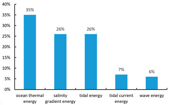
Figure 1.
Renewable energy reserves in China.
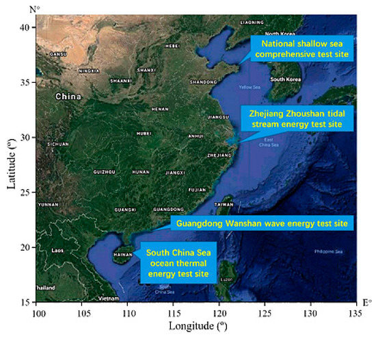
Figure 2.
Ocean energy demonstration bases in China.
The matter of how to use wave energy has become an important issue in coastal countries worldwide focused on economic development [30,31,32,33]. The common structures of wave energy converters, include oscillating water columns [34], overtopping devices and oscillating bodies [35,36,37]. Many countries have made plans to develop wave energy and have also developed various wave energy converters. Researchers in the US, Europe and Australia have previously developed these technologies, and therefore, some have already been commercially operated [38,39,40,41]. Table 1 shows the installed capacity (kW) of wave energy converter all over the world before 2016, including the installed capacity of future planned project, the installed capacity of project under development, and the installed capacity of running project [17].

Table 1.
The Installed Capacity of Wave Energy Converter All Over the World [42].
2. Engineering Model
Most wave energy converters convert energy through the application of hydraulic mechanisms. However, this paper is focused on direct drive wave energy converters. It does not discuss the energy conversion in the intermediate stage and introduces a new methodology. To meet the power demand on China’s coast and remote islands, as well as that of marine ranching, and utilize ocean energy more effectively, a new horizontal axis rotor wave energy direct drive generator has been designed. Its installed capacity is 6 kW, and it weighs 28 tons and measures 6 m long, 6 m wide and 5.4 m high. In addition, an engineering model has also been developed, as shown in Figure 3 [43]. The horizontal axis rotor is the core part of power generation with the diameter being 625 mm and length being 2000 mm. Thirty involute blades are distributed on the circumference evenly, as is shown in Figure 4. The exact dimensions of the engineering prototype and model prototype are shown in Table 2.
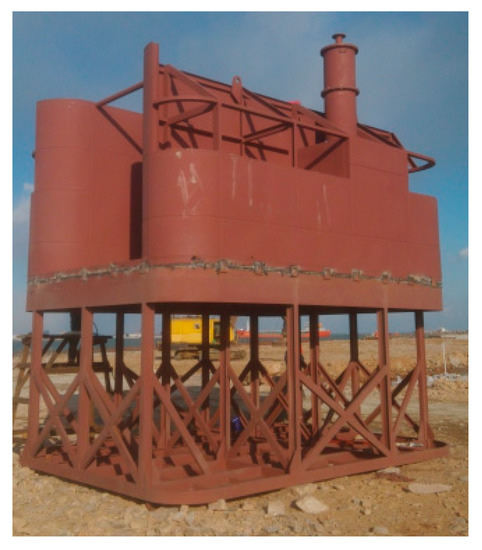
Figure 3.
Engineering model.
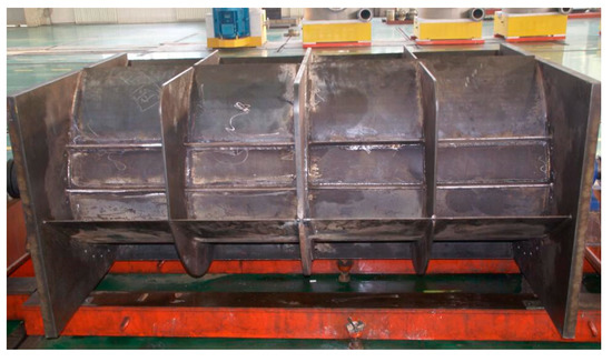
Figure 4.
Horizontal axis rotor.
Table 2.
Engineering Prototype and Model Prototype Dimensions.
3. Water Oscillation Mathematical Model
The wave flows into the flow channel from the wave inlet to impact the horizontal axis rotor. A closed water space is formed by a fluid channel running across the crossflow turbine. Under the impact and backflow of the incident wave, water moves back and forth in the fluid channel, driving the rotor to rotate in a single direction, and thus, driving the direct-drive generator to generate power. Figure 5 shows the profile chart of the horizontal axis rotor wave energy generator [44]. The generator can directly convert wave energy into power, thus maximizing its conversion efficiency, which is its main feature. The dynamic changes in water in the fluid channel driven by the outside wave can be simulated by a spring. The spring weight can be regarded as the water weight, and its resistance can be considered the gravitational force of water. The momentum is the product of the water weight and speed. The water is divided into eight units by nine sections [45]. The section, section and unit water in the inner wall of the fluid channel represent the units. The unit distance along the water flow is . The flow speed of the section is defined as, and the flow area of the section is . Assuming that the water cannot be compressed, i.e., the density is constant, the mass of the unit is , which is defined as follows:
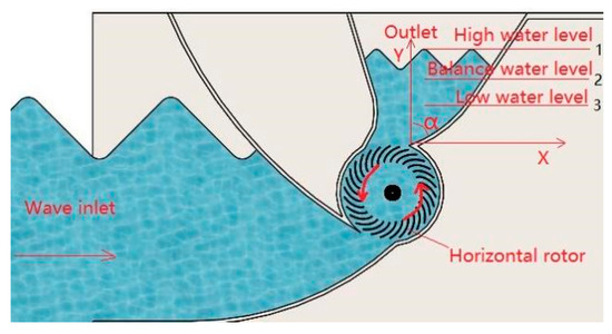
Figure 5.
Cutaway view of the device.
Let the speed of the unit be:, then the momentum of the unit is as follows,
Based on the function above, we can obtain the continuity equation as follows,
thus, Equation (2) is now as follows:
Let the distance between the water surface and equilibrium position be , the tilt angle of the exit backboard be , and the width of the generator perpendicular to the board surface be ; the area of Section 1 can be approximated as follows:
Water momentum consists of two parts, and the section and water flow will not change with time:
Let ; if the fluid channel type is fixed, is a constant. Because , , and the value is larger than the section of fluid channel .
Equation (6) can then be rewritten as follows,
where . Substituting Equation (5) into Equation (7) is as follows:
The part where the longitudinal length between the section and water changes with time is written as follows:
Therefore, it can be rewritten as follows:
Substituting Equation (5) into Equation (9) gives Equation (10):
After combining Equation (8) and Equation (10), Equation (11) is as follows:
Let the variables , , and be defined as follows:
Then, Equation (11) can be written as follows:
After taking the time derivative, Equation (16) can be written as follows:
According to Newton’s Second Law, changes in water momentum drive the restoring force, regardless of the viscous loss of water, and then the gravitational difference obtained by water acting on the equilibrium position can be derived as follow:
The momentum equation is , equation the following equation is obtained:
The equation above assumes that the fluid is in an ideal state. The value of speed and shift is not that big, so the high order of them can be rounded to:
Compared to mechanical oscillation, the following relationship is obtained,
where .
The master natural frequency of water oscillation can be calculated as follows:
As seen in the equation above, the value is related to and the coefficient . Based on Equations (12)–(15), there are only two variables, and , in the equation that act as a function of , so is a function of and :
The wave energy capture system is designed to maximize the water level amplitude in the fluid channel, so is both the target value and the control output. As a result, when , and are fixed, is both a variable and an input variable. In the later physical model experiment, the fixed frequency is changed as a function of to design the fluid channel of the power generator.
4. Physical Model Regular Wave Experiment
According to the experimental conditions, the design of experimental model is based on the similarity principle and taking into account the engineering condition and experimental tank condition, the model scale is 1:2.5. The main body of the model is made of organic glass and adopts aluminium alloy structure. The dimension of rotor is shown in Table 2. For the selection of the rotor blade shape, the rotor blade adopts evolvent and biarc generally. The theory shows that evolvent is superior to other shapes of blades, and the experiments also shows that evolvent rotor’s efficiency is high, so the evolvent blade is chosen. There are 30 blades, which are printed three-dimensional (3D) printer using ABS plastic in order to guarantee the machining precision of rotor, as is shown in Figure 6.

Figure 6.
Horizontal axis rotor.
The physical experiment is conducted in the National Engineering Laboratory of the NMEI Group Co., Ltd. (Qingdao, China). The experimental water tank is 30 m long, 4 m wide and 3 m high; the experimental model is 1.1 m long, 1 m wide and 1.8 m high. The model is installed 10 m away from the wave generator by a vehicle lift. It is fixed with a heavy block; the model prototype is shown in Figure 7. The model consists of five parts: 1. the clump weight, which is used to stabilize the generator and prevent it from moving under the impact of the waves; 2. the base support, which measures 1.4 m long, 1.4 m wide and 0.6 m high and increases the contact area between the model and the base of the water tank to stabilize the model; 3. the variable-angle fluid channel, which is designed to change the size of the water’s entrance and exit points; 4. the power generator, which consists of a generator, a torque sensor, a motor bracket, a concentric coordinate, a bearing and a synchronous belt that measures the torque and rotating speed of the horizontal axis rotor under wave conditions; 5. the horizontal axis rotor, which is the main component of the generator and can convert wave energy into mechanical energy and pass it to the torque sensor and generator through the synchronous belt.
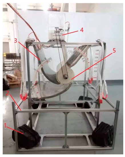
Figure 7.
Physical model.
The regular wave experiment is designed to verify whether the generator can generate the amount of power simulated in the water oscillation mathematical model. Under regular wave conditions, the following experiment is conducted: the rotating speed and torque of the torque sensor driven by the rotator is set and the initial performance of the horizontal axis rotor starting from a static condition to final rotation is examined to determine the torque change of the transmission shaft at varying water turbine speeds. The experimental device consists of an external adjustment platform and a main generator (Figure 8a,b).
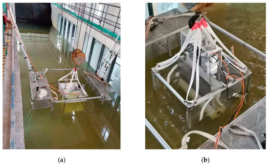
Figure 8.
Water tank experimental setup of model prototype: (a) Hoisting; (b) Model experiment.
During the experiment, the generated data are collected under regular wave conditions with the water depth set at 1.20 m. To guarantee the quality of the wave generation data, the ratio of the wave height to the wavelength must be less than 1/7 of the wave breaking condition, if the ratio is higher than 1/7 the wave becomes too steep and will break. The experimental conditions of the wave generation water tank are set based on the principle above (Table 3). Under the experimental conditions, regular wave experimental data from more than 5 cycles are used as the basis for analysis. The wave movement tends to stabilize 10 s after the experiment beings, and then the data are collected.
Table 3.
Experiment Condition.
In this experiment, data are collected by a scaled model data collection system, which is shown in Figure 9a,b. The acquisition system includes software and hardware, and the software window is designed with LabVIEW software programming. The system can collect important information regarding the torque, rotating speed, voltage, current and level change of the water inlet and outlet. The collection cycle is set at 0.01 s. To verify the feasibility of the fluid channel, which is designed based on the water oscillation mathematical model, the rotation speed and torque changes under the same operating conditions are analyzed to examine whether the model can operate under normal conditions. Normal operation shows that derivation from the water oscillation mathematical model is sufficient.
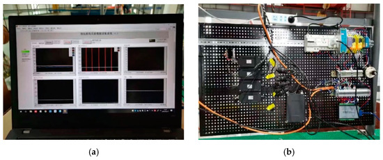
Figure 9.
Scaled model data collection system: (a) Software Interface; (b) Hardware part.
Figure 10 shows the changes in the rotator torque and rotating speed under the case 1. When the experiment cycle is 1.26 s and the wave height is 0.1 m, the average torque is 1.47 N.m, the average rotating speed is 29.73 r/min, and the generator can operate normally under this operating condition.
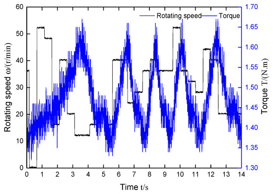
Figure 10.
The change process of torque and rotating speed in Case 1.
Figure 11 shows the changes in the rotator torque and rotating speed under the case 2. When the experiment cycle is 1.26 s and the wave height is 0.12 m, the average torque is 1.48 N.m, the average rotating speed is 31.16 r/min, and the generator can operate normally under this operating condition.
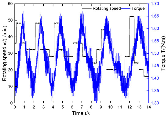
Figure 11.
The change process of torque and rotating speed in Case 2.
Figure 12 shows the changes in the rotator torque and rotating speed under the case 3. When the experiment cycle is 1.26 s and the wave height is 0.14 m, the average torque is 1.49 N.m, the average rotating speed is 48.91 r/min, and the generator can operate normally under this operating condition.
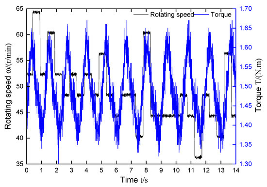
Figure 12.
The change process of torque and rotating speed in Case 3.
Figure 13 shows the average torque and rotational speed as a function of wave height with T = 1.26 s. The average torque and rotational speed increase with the increase of wave height, of which the change of average torque is insignificant and the change of average rotor is significant. The rotating speed and torque shift with the periodicity of the wave. The experimental results show that the physical model, which is designed according to the water oscillation mathematical model, can operate under regular wave conditions. When the experiment cycle stays the same, the average torque and rotational speed increase with the increase of wave height, of which the change of average torque is insignificant and the change of average rotational speed is significant.
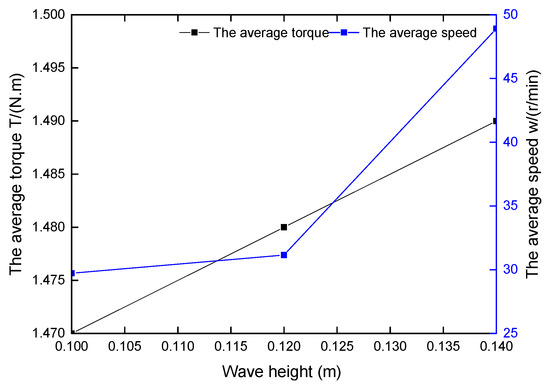
Figure 13.
The average torque and rotational speed as a function of wave height with T = 1.26 s.
5. Conclusions
The mathematical model is constructed by analyzing water movement and can be simplified as a single-degree-of-freedom oscillatory system. Resonance theory mainly studies the phenomenon at the point of resonance, but the energy of the incident wave is focused within a frequency range, so the mathematical model is of great significance for studying how to absorb wave energy within a certain frequency range. The mathematical model, derived from the natural frequency formula of water movement, is used to analyze water movement in the generator. The formulas show that the water characteristic length in the generator and the backboard tilt angle at the exit point of the fluid channel are two design variables that can change its natural frequency; the physical model fluid channel is designed based on the water movement mathematical formula, and the physical model can be operated normally under regular wave conditions; when the experiment cycle stays the same, the wave height affects the rotational speed significantly. This provides a basis for developing further experiments and engineering prototypes.
Author Contributions
Conceptualization, Z.M. and Y.L.; methodology, Z.M. and Y.L.; software, Y.C. and J.Q.; validation, Y.L.; investigation, Z.M. and Y.L.; resources, Y.L.; data curation, Y.L.; writing—review and editing, Z.M.; supervision, Y.L. All authors have read and agreed to the published version of the manuscript.
Funding
This research was funded by the National Nature Science Foundation of China (U1706230), the Major Scientific and Technological Innovation Projects of Shandong Province (2018CXGC0104).
Acknowledgments
The authors are grateful for the financial support provided by the Major Scientific and Technological Innovation Projects of Shandong Province. In addition, thank you very much for the support provided by the cooperation project of China Institute of Water Resources and Hydropower Research.
Conflicts of Interest
The authors declare no conflict of interest.
References
- Østergaard, P.A.; Duic, N.; Noorollahi, Y. Sustainable development using renewable energy technology. Renew. Energy 2020, 146, 2430–2437. [Google Scholar] [CrossRef]
- Mwasilu, F.; Jung, J. Potential for power generation from ocean wave renewable energy source: A comprehensive review on state-of-the-art technology and future prospects. IET Renew. Power Gener. 2019, 13, 363–375. [Google Scholar] [CrossRef]
- Segura, E.; Morales, R.; Somolinos, J.A. A strategic analysis of tidal current energy conversion systems in the European Union. Appl. Energy 2018, 212, 527–551. [Google Scholar] [CrossRef]
- Melikoglu, M. Current status and future of ocean energy sources: A global review. Ocean Eng. 2018, 148, 563–573. [Google Scholar] [CrossRef]
- Roy, A.; Auger, F.; Dupriez-Robin, F. Electrical Power Supply of Remote Maritime Areas: A Review of Hybrid Systems Based on Marine Renewable Energies. Energies 2018, 11, 1904. [Google Scholar] [CrossRef]
- Lehmann, M.; Karimpour, F.; Goudey, C.A. Ocean wave energy in the United States: Current status and future perspectives. Renew. Sustain. Energy Rev. 2017, 74, 1300–1313. [Google Scholar] [CrossRef]
- Peiyue, L.; Lu, L.; Xiaohua, G. Talking about the issue of global warming. Environ. Sci. Manag. 2009, 34, 49–52. [Google Scholar]
- Aderinto, T.; Li, H. Ocean Wave Energy Converters: Status and Challenges. Energies 2018, 11, 1250. [Google Scholar] [CrossRef]
- Wang, Z.; Carriveau, R.; Ting, D.S.K. A review of marine renewable energy storage. Int. J. Energy Res. 2018, 43, 6108–6150. [Google Scholar] [CrossRef]
- Hemer, M.A.; Zieger, S.; Durrant, T. A revised assessment of Australia’s national wave energy resource. Renew. Energy 2017, 114, 85–107. [Google Scholar] [CrossRef]
- Chang, Y.; Wang, N. Legal system for the development of marine renewable energy in China. Renew. Sustain. Energy Rev. 2017, 75, 192–196. [Google Scholar] [CrossRef]
- Chao, P. A Preliminary Study on the Sustainable Development of My Country’s Islands. Ph.D. Thesis, Ocean University of China, Qingdao, China, 2006. [Google Scholar]
- Chongwei, Z.; Lin, Z.; Lijia, Z. The seasonal variation characteristics of waves and wave energy in Xisha and Nansha waters. Adv. Mar. Sci. 2011, 29, 419–426. [Google Scholar]
- Doyle, S.; Aggidis, G.A. Development of multi-oscillating water columns as wave energy converters. Renew. Sustain. Energy Rev. 2019, 107, 75–86. [Google Scholar] [CrossRef]
- Kaijian, F.; Guangtao, N.; Liyi, H. Research on Wave Energy Development and Utilization of South China Sea Islands. Eng. Technol. Res. 2020, 5, 216–217. [Google Scholar]
- Wan, Y.; Fan, C.; Dai, Y. Assessment of the Joint Development Potential of Wave and Wind Energy in the South China Sea. Energies 2018, 11, 398. [Google Scholar] [CrossRef]
- Magagna, D.; Uihlein, A. Ocean energy development in Europe: Current status and future perspectives. Int. J. Mar. Energy. 2015, 11, 84–104. [Google Scholar] [CrossRef]
- Khan, N.; Kalair, A.; Abas, N. Review of ocean tidal, wave and thermal energy technologies. Renew. Sustain. Energy Rev. 2017, 72, 590–604. [Google Scholar] [CrossRef]
- Li, Y.; Pan, D. The ebb and flow of tidal barrage development in Zhejiang Province, China. Renew. Sustain. Energy Rev. 2017, 80, 380–389. [Google Scholar] [CrossRef]
- Xiangnan, W.; Ning, J.; Caixia, X. Thoughts on the industrialization of marine renewable energy in my country. Ocean Dev. Manag. 2019, 36, 14–18. [Google Scholar]
- Weimin, L.; Lei, L.; Fengyun, C. Progress in China’s marine renewable energy technology. Sci. Technol. Rev. 2020, 38, 27–39. [Google Scholar]
- Qijuan, C.; Gongzheng, G.; Xuhui, Y. Opportunities and Challenges of Hydropower and New Energy: Research Progress of Wave Energy Technology. Hyd. New Energy 2020, 34, 1–6. [Google Scholar]
- Zhe, M.; Naibo, H.; Youxun, L. Research on the development status and countermeasures of marine renewable energy industry in Shandong Province. Sci. Technol. Ind. 2020, 20, 63–67. [Google Scholar]
- Linsheng, H.; Jing, W.; Jia, G. Analysis of wave energy resources in the northern waters of Chu Island, Shandong. Acta Energy Sol. Sin. 2020, 41, 165–171. [Google Scholar]
- Yong, W.; Chenqing, F.; Yongshou, D. Study on the wave energy development potential of the coastal waters around Shandong Peninsula. Acta Energy Sol. Sin. 2018, 39, 3311–3318. [Google Scholar]
- Shouwei, Z.; Qingping, L. Exploit ocean energy and build a maritime power. Sci. Technol. Rev. 2020, 38, 17–26. [Google Scholar]
- Qiu, S.; Liu, K.; Wang, D. A comprehensive review of ocean wave energy research and development in China. Renew. Sustain. Energy Rev. 2019, 113, 109271. [Google Scholar] [CrossRef]
- The 13th Five-Year Plan for Renewable Energy Development (Part 1). Solar Energy 2017, 2, 5–11.
- The 13th Five-Year Plan for Renewable Energy Development (Part 2). Solar Energy 2017, 3, 5–12.
- Uihlein, A.; Magagna, D. Wave and tidal current energy-A review of the current state of research beyond technology. Renew. Sustain. Energy Rev. 2016, 58, 1070–1081. [Google Scholar] [CrossRef]
- Neill, S.P.; Vögler, A.; Goward-Brown, A.J. The wave and tidal resource of Scotland. Renew. Energy 2017, 114, 3–17. [Google Scholar] [CrossRef]
- Zhou, Z.; Benbouzid, M.; Charpentier, J. Developments in large marine current turbine technologies-A review. Renew. Sustain. Energy Rev. 2017, 71, 852–858. [Google Scholar] [CrossRef]
- Guillou, N.; Lavidas, G.; Chapalain, G. Wave Energy Resource Assessment for Exploitation-A Review. J. Mar. Sci. Eng. 2020, 8, 705. [Google Scholar] [CrossRef]
- Liu, Z.; Hyun, B.; Hong, K. Numerical Study of Air Chamber for Oscillating Water Column Wave Energy Convertor. China Ocean Eng. 2011, 25, 169–178. [Google Scholar] [CrossRef]
- Martin, D.; Li, X.; Chen, C. Numerical analysis and wave tank validation on the optimal design of a two-body wave energy converter. Renew. Energy 2020, 145, 632–641. [Google Scholar] [CrossRef]
- Martins, J.C.; Goulart, M.M.; Gomes, M.D.N. Geometric evaluation of the main operational principle of an overtopping wave energy converter by means of Constructal Design. Renew. Energy 2018, 118, 727–741. [Google Scholar] [CrossRef]
- Ahamed, R.; Mckee, K.; Howard, I. Advancements of wave energy converters based on power take off (PTO) systems: A review. Ocean Eng. 2020, 204, 107248. [Google Scholar] [CrossRef]
- Nguyen, H.P.; Wang, C.M.; Tay, Z.Y. Wave energy converter and large floating platform integration: A review. Ocean Eng. 2020, 213, 107768. [Google Scholar] [CrossRef]
- Li, N.; Cheung, K.F.; Cross, P. Numerical wave modeling for operational and survival analyses of wave energy converters at the US Navy Wave Energy Test Site in Hawaii. Renew. Energy 2020, 161, 240–256. [Google Scholar] [CrossRef]
- Vieira, F.; Cavalcante, G.; Campos, E. Wave energy flux variability and trend along the United Arab Emirates coastline based on a 40-year hindcast. Renew. Energy 2020, 160, 1194–1205. [Google Scholar] [CrossRef]
- Mctiernan, K.L.; Sharman, K.T. Review of Hybrid Offshore Wind and Wave Energy Systems. J. Phys. Conf. Ser. 2020, 1452, 12016. [Google Scholar] [CrossRef]
- Ocean Energy Systems. Annual Report Ocean Energy Systems 2016. 2017. Available online: https://report2016.ocean-energy-systems.org/ (accessed on 11 March 2018).
- Xiaochen, G.; Shuiwei, T.; Yihong, W. Research on the wave energy capture device in the flow channel of the double-click water wheel. J. Ocean Technol. 2014, 33, 17–24. [Google Scholar]
- Xiaochen, G.; Yihong, W. Research on power bandwidth design method of wave energy utilization device of direct drive turbine. J. Hydrog. Eng. 2013, 32, 197–203. [Google Scholar]
- Xiaochen, G. Theory and Practice of Research and Development of Double-Click Turbine Wave Energy Power Generation Device; China Water Resources and Hydropower Press: Beijing, China, 2017; pp. 23–25. [Google Scholar]


Publisher’s Note: MDPI stays neutral with regard to jurisdictional claims in published maps and institutional affiliations. |
© 2020 by the authors. Licensee MDPI, Basel, Switzerland. This article is an open access article distributed under the terms and conditions of the Creative Commons Attribution (CC BY) license (http://creativecommons.org/licenses/by/4.0/).