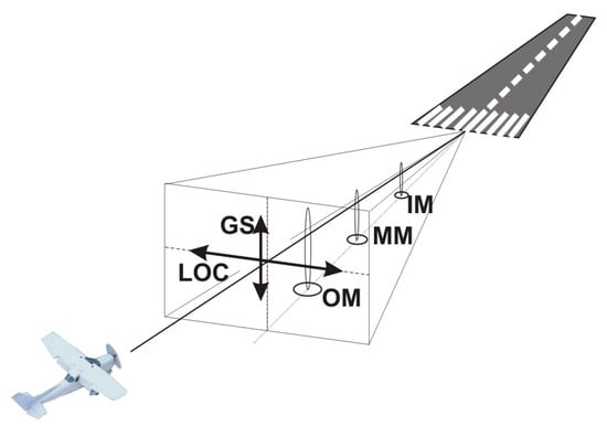
Abstract
The paper depicts research concerning the value of the electric component of the electromagnetic (EM) energy determined by the NHT3DL meter by Microrad with the 01E measuring probe during a number of flights made by Aero AT-3 R100, Cessna C172, and Tecnam P2006T fixed wing aircrafts and a Robinson R44 Raven helicopter. The point of reference for the recorded measurement was the normative limits of the electromagnetic field (EMF), which can influence a pilot in the course of a flight. Selected studies of the maximum value recorded by the meter was E = 10.66 V/m when landing at an airfield equipped with the VHF (Very High Frequency) omnidirectional radio range (VOR) approach system. Particular attention has been paid to changes in electric field intensity during the operation and their effects on the type of radio navigation systems as well as communication with the airfield control tower. The obtained results were validated in the Statistica 13.3 software for the purpose of a detailed stochastic analysis of the tested values. Results obtained are subject to the mandatory requirements of Directive 2013/35/EU as well as to the relevant regulations in Poland.
1. Introduction
The influence of (electromagnetic) EM energy on human organisms is the topic of research in many research centers around the world. There are no clear criteria for assessing its effects. The International Commission on Non-Ionizing Radiation Protection (ICNIRP) describes guidelines providing protection against adverse health effects related to exposure to non-ionizing radiation [1,2]. Preventing undesirable effects on the human organism and the environment is the main goal of protection against ionizing and non-ionizing radiation. The electromagnetic field energy is present in the world around us, but we should focus on its tolerable level. The level of the exposure threshold is necessary for the negative health effects to be present. The limits of the electromagnetic field (EMF) take into account the presence of direct and indirect health effects. They refer to exposure regardless of its duration and include the effects of both short-term and long-term exposure [3,4].
In general, measurements of the electromagnetic field of radio navigation equipment are carried out in function checks of newly installed systems or for diagnostic purposes. In such instances, airplanes with measuring equipment or ground measuring systems are used [5,6,7].
In the literature, studies on the quantitative determination of air crew exposure to the energy of electromagnetic fields are rare. It is also difficult to find studies dealing with passenger exposure. The ICNIRP commission undertakes extensive research in a similar field, however, it is usually only related to the effects of EM field energy on ground handling staff [8,9].
Novak (2012) used a Piper PA-34-220T airplane equipped with on-board instrumentation together with ground instrumentation for the comparative aerial measurements of the newly installed Instrument Landing System (ILS) at the Zilina Airport, Slovakia [10]. Another example of research in this area is the use of simulation methods to assess the accuracy and operational characteristics of the ILS system [11]. Apart from simple electronic systems, airplanes also have advanced avionics devices. On-board electronics and flight control instruments use most of the electric power distributed by the aircraft’s power system. This is often associated with significant current densities in the power lines, which in turn generate the electromagnetic field of the devices themselves and the entire working space of the aircraft. In addition to the electromagnetic field energy from on-board devices, to which the pilot and passengers are exposed, a number of ground devices for guidance and communication with the airport emit an electromagnetic field [12,13].
The intensity of the electric component of the electromagnetic field for aircrafts crews was related to the guidelines of Directive 2013/35/EU [14], in which reference levels for time-averaged exposures of ≥6 min were given. The directive provides Action Levels (ALs) for exposure to electric fields of frequency 100 kHz–300 GHz, ALs (E) (RMS) = 61 V/m as the maximum value. The legal regulations for reference levels for time-averaged general public exposures of ≥6 min and for electromagnetic fields from 100 kHz to 300 GHz were compared with the normative values presented by ICNIRP. Both guidelines indicate the same value for general public and occupation. On the other hand, legal regulations in Poland are more stringent. According to the regulation of the Ministry of Health, in the work environment, the normative values are defined as intervention exposure levels; ALs where E = 7 V/m refer to the safe zone for pilots and ground handling staff [15], and for places accessible to the public where E = 28 V/m [16]. Interpretation of the results concerned the frequency bands of radio navigation systems.
Monitoring and measurement of the EMF generated by the operating devices is curtailed not only from the point of view of environmental and human body protection but also in regard to the electromagnetic compatibility [17,18]. Therefore, the following research gives the results of a study that carried out EMF measurements on various aircrafts of the Aviation Training Center in Royal Depultycze near Chelm, Poland. This center provides training for ATPL licenses on airplanes and helicopters as a part of engineering studies. The increasing load of the EMF in light aircrafts can lead to negative effects on pilots’ health and mental condition, especially when it comes to instructors flying multiple-hour flights daily, which can also cause safety risks [19]. It is worth adding that the quantitative assessment of field effects at the workplace is important, especially since contemporary research indicates that possible long-term effects include effects on the reproductive system (asthenozoospermia, oligozoospermia, necrozoospermia), disturbances in memory processes, sleep disorders and their complicated forms, endocrinological disorders, and severe psychosomatic medical conditions [20,21,22].
Taking into account the measurements and methodology, the paper presents a different approach to the issue of both the electromagnetic field and crew exposure. Typically, tests of devices in the context of electromagnetic compatibility are performed in laboratories on the ground. The presented research depicts an innovative approach to the analysis of the electromagnetic field energy affecting pilots, staff, passengers, and the avionics devices themselves during high-altitude flight, which may affect flight safety.
The aim of the study was to quantify training aircraft crews’ exposure to electric field energy, with particular emphasis on components originating from radio navigation devices. Experimental studies were undertaken with the use of real objects (airplanes) and measurements were made during the flight.
3. Materials and Methods
3.1. The Test Airplanes
Measurements of the electric component (E) of EMF were carried out in four different aircraft: an Aero AT-3 R100, a Cessna C172, a Tecnam P2006T, and a Robinson R44 Raven helicopter. The measurements were carried out in accordance with the PN-T-06580-3: 2002 standard [26], which defines the methods of measuring and assessing EMF at workplaces with frequencies from 0 Hz to 300 GHz. The airplanes presented are used every day for flight training in the Center of Aviation of the State School of Higher Education in Chełm, Poland.
The AT3 R100 is the smallest aircraft used for the tests. Its origin is connected with an amateur design, Pottier P220, which was a popular homebuilt aircraft. Although the AT3 resembles the P220, it is a completely new design, with major structural and conceptual changes that were necessary to comply with certification regulations. As mentioned, it is a small airplane (wingspan 7.60 m) with two side-by-side seats. The airplane is certified for VFR (Visibility Flight Rules) flights, however it is equipped with most of the IFR instruments for primary training in IR flights. Therefore, some of the avionics are placed in unusual locations, for example under the seats.
The Cessna 172 and the Robinson R44 Raven are widely used general aviation aircrafts. They are very popular as training aircrafts and are equipped with full IFR avionics.
The Tecnam P2006T aircraft is a twin engine type with retractable landing gear. It is powered by a pair of Rotax piston engines and is certified for IR flights, being equipped with the IFR instruments.
All the four aircrafts used in the test flights are of metal construction.
3.2. The Device for the Test of Electromagnetic Fields
The E tests were carried out with the NHT3DL meter by Microrad, with the 01E measuring probe (Figure 2). The device is used for measurements and tests of electromagnetic fields in a wide range of frequencies present in the general environment as well as in the working environment in accordance with the international standards as described in [27]. The measurement of the electrical and magnetic components of the electromagnetic field takes place in the three directions X. Y. and Z for the peak impulse value (PEAK) and the effective value (RMS), which determines the maximum value in time. In terms of high frequency, the effective value (RMS) is most often adopted in standards and legal acts [28].
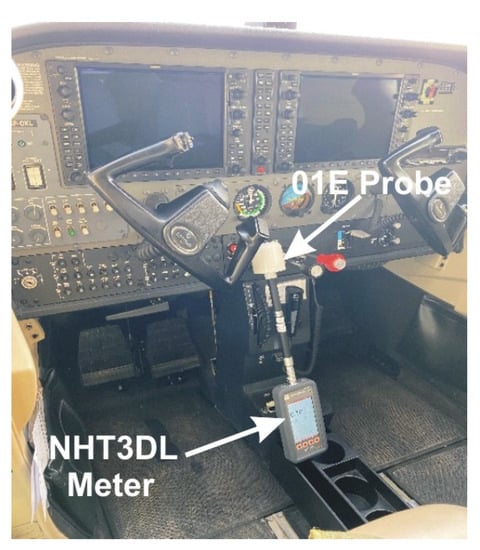
Figure 2.
The Microrad NHT3DL electric field meter with 01E measuring probe, installed in the Cessna C172 aircraft.
The obtained values are saved to the device memory using an SD card. The meter, with a built-in temperature and humidity sensor, is located in the housing. Figure 2 shows the measuring device with the probe. The device enables the measurement of fields emitted by such groups of objects as industrial devices, medical devices, transformer stations, high-voltage lines, railways, the defense industry, radio transmitters, wireless telecommunication systems (base stations, mobile phone, broadcasting equipment, satellite, communication equipment). A measuring probe marked as 01E was used.
The 01E probe is commonly used to detect both CW (Continuous Wave) and modulated signals in the frequency ranges from 100 kHz to 6.5 GHz, which in turn allow applications in the industrial, scientific, medical, telecommunications, and power plants sectors. The high sensitivity of the 01E probe makes it capable of measuring human exposure to electric fields in both public and environmental conditions [29].
The technical parameters of the probe are presented in Table 2.

Table 2.
The technical parameters of the probe [30].
The measurements of EM energy took place from the moment the crew started taxiing until they stopped after landing.
3.3. The Flight Test Campaign
As already mentioned, the measurements were carried out under real conditions during flights of the training aircrafts mentioned above. As the aim of the work was to investigate the influence of individual radio and navigation devices on the strength of the electromagnetic field in the plane, the measurements were started at the beginning of the landing approach, during IFR flights.
In order to analyze the electric field strength, measurements were made on various flights that lasted from 1 h to 4.6 h. A total of 12 flights were made, 3 flights on each plane. As part of the flight test campaign, measurements were carried out during the procedural approach to landing using the ILS system. Moreover, the measurements were carried out during en-route flights with the use of VOR and GPS radio navigation aids, as well as during navigation exercises in the controlled zone of the Depułtycze Królewskie airport. The flights were carried out both during the day and at night, in various weather conditions, but the use of radio navigation devices was the same, regardless of the conditions.
4. Results and Discussion
This section presents the results of selected E measurements by means of the NHT3DL meter with the E01 measuring probe. The obtained RMS values to which the regulations refer were analyzed. Figure 3, Figure 4 and Figure 5 show the measurement results of the electric component of EMF in the Aero AT 3.
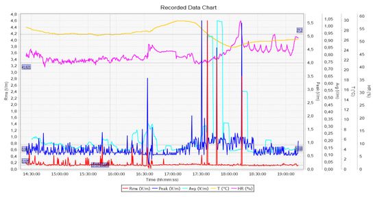
Figure 3.
The intensity of the electrical component of the electromagnetic field in the course of flight no. 1 for the Aero AT3.
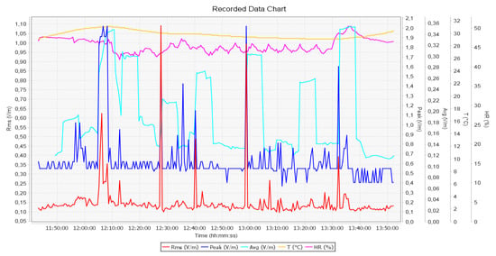
Figure 4.
The intensity of the electrical component of the electromagnetic field in the course of flight no. 2 for the Aero AT3.
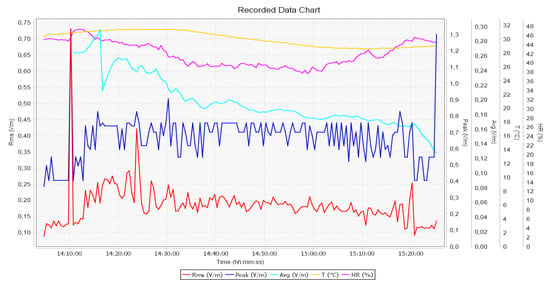
Figure 5.
The intensity of the electrical component of the electromagnetic field in the course of flight no. 3 for the Aero AT3.
The maximum values of the electric field strength where E = 4.59 V/m were observed during the approach to landing for the flight marked as AT3 no. 1. At this point, the aircraft was on the VOR approach path. Comparing the results for the flight marked as AT3, flights no. 4 and no. 5 were training flights without approach to landing at Lublin airport, where ILS and VOR navigation devices are installed. The highest values of electric field strength were present during radio correspondence with Depultycze Krolewskie airfield tower, where E = 0.73–1.09 V/m. The next aircraft analysis was the Cessna C172 (Figure 6, Figure 7 and Figure 8). Selected flights took place with an approach to landing at Lublin airport (VOR, ILS).
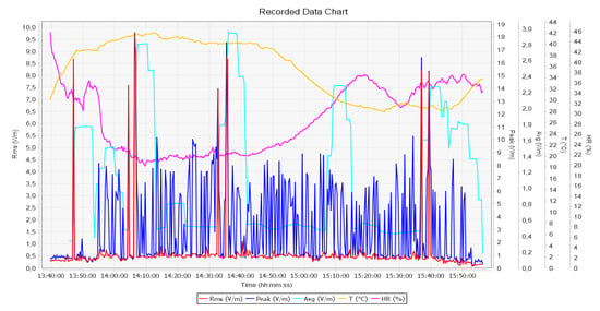
Figure 6.
The intensity of the electrical component of the electromagnetic field in the course of flight no. 1 for the Cessna 172.
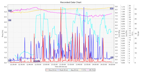
Figure 7.
The electric field in the course of flight no. 2 for the Cessna 172.
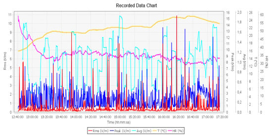
Figure 8.
The intensity of the electrical component of the electromagnetic field in the course of flight no. 3 for the Cessna 172.
For flight no. 1 with the Cessna 172, the maximum values to which the pilot and the passenger were exposed were E = 9.75 V/m. On the basis of the analysis, it was noticed that the maximum values of E = 8–9.75 V/m occurred during landing phase with the VOR system.
The high value of E = 5. 45 V/m was recorded during an ILS approach. The aircraft at this point entered the ILS approach path. In this case, values between 2.5–3 V/m are present during communication with the airport.
The maximum values of the electrical component of the electromagnetic field during the measurement at the landing phase (VOR) were reached with Cessna 172 flight no. 3, where E = 10.66 V/m. It is important to notice that they are several times higher than during non-approach flights at airports equipped with instrument landing systems. The value of E during the landing range went from 5 V/m to the maximum during this flight, 10.66 V/m.
Then measurements were made during the flight of the Tecnam P2006T. The values described in Figure 9, Figure 10 and Figure 11 record the results obtained by means of the meter in the Tecnam P2006T.
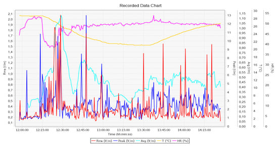
Figure 9.
The intensity of the electrical component of the electromagnetic field in the course of a flight for the Tecnam P2006T flight no 1.
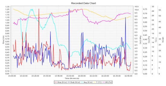
Figure 10.
The intensity of the electrical component of the electromagnetic field in the course of flight no. 2 for the Tecnam P2006T.
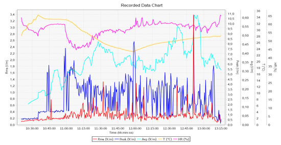
Figure 11.
The intensity of the electrical component of the electromagnetic field in the course of flight no. 3 for the Tecnam P2006T.
For the Tecnam P2006T flight no. 1, the highest values of E = 2.0 V/m were read at the VOR approach path.
For the second training flight in the Tecnam P2006T aircraft, the highest values recorded showed that E = 1.25 V/m during correspondence with the airport. The analyzed flights (Figure 11 and Figure 12) took place in a circuit pattern without ILS and VOR systems.
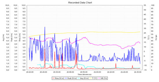
Figure 12.
The intensity of the electrical component of the electromagnetic field in the course of flight no. 1 for the Robinson R44.
The maximum result of the intensity of the electric component of the electromagnetic field for the Tecnam P2006T flight no. 1 obtained in the course of the measurement with the meter was E = 3.3 V/m. This value was recorded while connecting to the GPS.
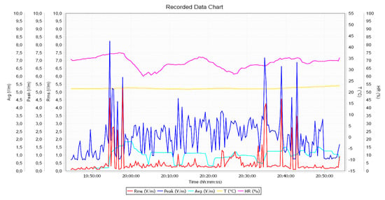
Figure 13.
The intensity of the electrical component of the electromagnetic field in the course of flight no. 2 for the Robinson R44.
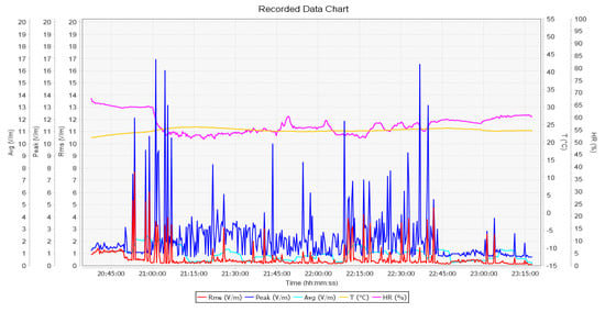
Figure 14.
The intensity of the electrical component of the electromagnetic field in the course of flight no. 3 for the Robinson R44.
For the Robinson R44 helicopter flight no. 1, the highest values of the electric component, where E = 3.22 V/m, were read for the correspondence with the airport via radio.
For flight no. 2, the maximum values of the electrical component were E = 5.23 V/m. At this test point, the helicopter was at the VOR approach path. The remaining values of the electric component at the VOR point vary in the range of 3.1–5.0 V/m.
For flight no. 3 with the R44 aircraft, the highest values were also recorded, where E = 7.81 V/m. The helicopter was also in the range of the VOR system. The observed values in the range of 3.0–4.0 V/m were obtained during correspondence with the airport.
In order to observe the regularities in the studied electromagnetic field phenomena resulting from the large number of samples obtained by measurements, a statistical analysis was performed. The statistical analysis implemented values of the electric field intensity measurement by the NHT3DL meter into the Statistica 13.3 software. The values of the analyzed variables are determined by the mean value, median, standard deviation (SD), and range of variation. The researchers assumed an error of inference which equals 5%, and the level of significance was p < 0.05. The characteristics of electric field for selected flights are depicted in Table 3.

Table 3.
Characteristics of the intensity of the electrical component of the electromagnetic energy E, in V/m, for testing airplanes.
The average electric fields value for the analyzed airplanes ranges from 0.147–0.624 V/m. The parameters of the tested quality is very high, in the range of 0.013 V/m–10.87 V/m. In order to verify this hypothesis, the differences between the indicated airplanes tests obtained with the NHT3DL meter are presented in Figure 15.
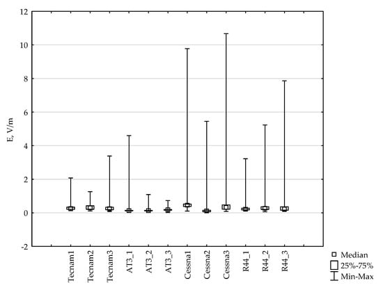
Figure 15.
Range of quality and median of electromagnetic (EM) energy during airplane flight.
It can be observed that values exceeding the electric field limit occur in selected Cessna 172 and Robinson R44 flights. Figure 16 presents a frame-moustache graph with marked averages and standard deviation.
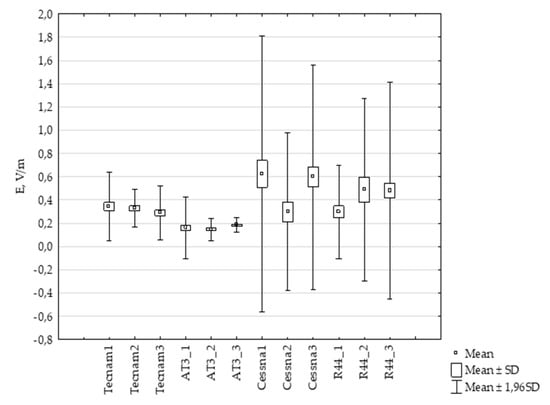
Figure 16.
Box plots of measurements of the electric component of electromagnetic fields.
From Figure 16, it can be observed that there are differences in the mean of the electric component of electromagnetic fields between different types of airplanes. In order to establish whether there are statistically significant differences between the electric fields for particular types of testing airplanes, the Student’s t-test (Table 4) was carried out.

Table 4.
Test results for individual comparisons (aircrafts). p—statistical significance.
Comparing the levels of intensity of the electric component in different types of airplanes, statistically insignificant differences were found for Tecnam 1 vs. Tecnam 2, AT3_1 vs. AT3_2, Cessna 1 vs. Cessna 3, and Robinson R44_2 vs. R44_3.
5. Conclusions
Measurements of the electromagnetic field in training airplanes were carried out using the Microcard NHT3DL electromagnetic field meter with the 01E probe, during flights, on the landing approach supported by radio navigation systems. During the measurements, the meter was placed between the front seats of the pilots. The obtained measurement results were subjected to statistical analysis. It was concluded as follows:
- The values of the electromagnetic field electric component, recorded during the test flights of all the analyzed aircraft types (Aero AT-3 R100, Cessna C172, Tecnam P2006T, and Robinson R44 Raven) with relation to the Directive 2013/35/EU (in terms of health protection, safety, and exposure of workers to hazards caused by physical factors) remain within the limits of the indicated standard.
- According to the current regulations by the Minister of Labor, Family, and Social Policy of 27 June 2016, in line with detailed guidelines in force in Poland regarding the exposure of the aircraft crew, the recorded RMS values were: E = 10.66 V/m, E = 9.77 V/m, E = 7, 81 V/m for Cessna flight no. 1, Cessna flight no. 3, and Robinson R44 flight no. 3 are considered to be over-normative. The recorded results concerned the landing phase when VOR system was used.
- The use of the VOR system during the approach phase of the Aero AT-3 R100 aircraft also resulted in a high recorded maximum value of E = 4.59 V/m.
- The short-range, radio-assisted navigation system (ILS) generated increased values of the electric field. The range of 2.5–5.45 V/m for the Cessna C172 aircraft should be specified here, however, the values allowed in the regulation were not exceeded here.
- Larger field interactions and higher field strengths in the VOR beacon system compared to the ILS system can be correlated with the purpose of the system, in particular with the power of transmitting devices. It went up to 200 W in the case of VOR and up to 50 W in the short-range ILS guidance system.
- Approaches at airports not equipped with VOR and ILS directional radiolocation systems in all cases resulted in maximum electric field strengths of 0.4–2.5 V/m being registered. It should be noted that the values of the intensity of the electromagnetic field electric component, where E = 2.5 V/m, were recorded only when the crew communicated with the control tower via radio stations.
- Particularly high values of the electric field’s electric component intensity were recorded in the Cessna C172, the sheet of which is aluminum, riveted to the spar and ribs, and communication devices were located in the immediate vicinity of the pilot’s seat.
- During the tests, very high values of up to E = 18.5 V/m (electrical component) were noted. These values were omitted in the interpretation of the results, as the indicated standards refer only to RMS values. As for the regulation established by the Minister of Health in December 17, 2019, concerning potential passengers traveling by air, the normative values were not exceeded.
Therefore, a representative group of instructor pilots should be tested to identify trends. This will be the subject of our team’s future research work. Another interesting topic is the study of exposure to electromagnetic energy in electric powered trainer airplanes. This is especially important in the era of the global development of the aviation industry and the regional development of aviation infrastructure.
Author Contributions
Conceptualization. J.M., J.P.; Methodology. J.M. and J.P., P.K.; Software. J.M.; Formal Analysis. J.M., J.P.; Investigation. J.M.; Resources. J.M. and J.P.; Data Curation. A.T., Ł.P.; Writing—Original Draft Preparation. J.M., J.P.; Writing—Review & Editing. J.M., J.P., P.K.; Visualization. J.M.; Supervision. A.T., Ł.P.; All authors provided critical feedback and collaborated in the paper. All authors have read and agreed to the published version of the manuscript.
Funding
This research received no external funding.
Institutional Review Board Statement
Not applicable.
Informed Consent Statement
Informed consent was obtained from all subjects involved in the Study.
Data Availability Statement
Not applicable.
Conflicts of Interest
The authors declare no conflict of interest.
References
- International Commission on Non-Ionizing Radiation Protection (ICNIRP). Guidelines for Limiting Exposure to Electromagnetic Fields (100 kHz to 300 GHz). Health Phys. 2020, 118, 483–524. [Google Scholar] [CrossRef] [PubMed]
- Zubrzak, B.; Bienkowski, P. Methods for controlling the levels of electromagnetic fields in the environment. Przegląd Elektrotechniczny 2019, 96, 94–97. [Google Scholar]
- Gas, P. Modelling the temperature-dependent RF ablation produced by the multi-tine electrode. Przegląd Elektrotechniczny 2020, 96, 48–51. [Google Scholar] [CrossRef]
- Li, X.; Zheng, J.; Mei, F.; Sha, H.; Li, D. An Early Warning Method of TCU Failure in Electromagnetic Environment Based on Pattern Matching and Support Vector Regression. Energies 2020, 13, 5537. [Google Scholar] [CrossRef]
- Manual on Testing of Radio Navigation Aids, DOC 8071, Vol. 1—Testing of Ground-Based Radio Navigations System, ICAO, Fourth Edition—2000. Available online: http://www.icscc.org.cn/ (accessed on 2 December 2020).
- Novak, A.; Havel, K.; Janovec, M. Measuring and Testing the Instrument Landing System at the Airport Zilina. Transp. Res. Procedia 2017, 28, 117–126. [Google Scholar] [CrossRef]
- Pitor, J.; Skultety, F.; Götz, K. Non directional beacons checking. Transp. Commun. Sci. J. 2014, 2, 12–16. [Google Scholar] [CrossRef]
- Frivaldsky, M.; Pavelek, M. In Loop Design of the Coils and the Electromagnetic Shielding Elements for the Wireless Charging Systems. Energies 2020, 13, 6661. [Google Scholar] [CrossRef]
- Menéndez, O.; Romero, L.; Cheein, F.A. Serial Switch Only Rectifier as a Power Conditioning Circuit for Electric Field Energy Harvesting. Energies 2020, 13, 5279. [Google Scholar] [CrossRef]
- Novák, A.; Havel, K.; Janovec, M. Využitie Výskumných Letových Laboratórií vo Svete a EÚ. Transp. Res. Procedia 2012, 68. [Google Scholar]
- Merkisz, J.; Galant, M.; Bieda, M. Analysis of Operating Instrument Landing System Accuracy under Simulated Conditions. Sci. J. Sil. Univ. Technol. Series Transp. 2017, 94, 163–173. [Google Scholar] [CrossRef]
- Michalowska, J.; Pytka, J.; Tofil, A.; Jozwik, J.; Puzio, Ł.; Krupski, P. The assessment of electromagnetic field in commonly used training aircrafts. In Proceedings of the 2020 IEEE 7th International Workshop on Metrology for AeroSpace (MetroAeroSpace), Pisa, Italy, 22–24 June 2020; pp. 249–254. [Google Scholar] [CrossRef]
- Michałowska, J.; Tofil, A.; Józwik, J.; Pytka, J.; Legutko, S.; Siemiątkowski, Z.; Łukaszewicz, A. Monitoring the Risk of the Electric Component Imposed on a Pilot during Light Aircraft Operations in a High-Frequency Electromagnetic Field. Sensors 2019, 19, 5537. [Google Scholar] [CrossRef] [PubMed]
- Directive 2013/35/EU of the European Parliament and of the Council of 26 June 2013 on the Minimum Health and Safety Requirements Regarding the Exposure of Workers to the Risks Arising from Physical Agents. Available online: https://eur-lex.europa.eu/legal-content/EN/TXT/?uri=celex%3A32013L0035 (accessed on 1 December 2020).
- Rozporządzenie Ministra Rodziny, Pracy i Polityki Społecznej z dnia 12 Czerwca 2018 r. w Sprawie Najwyższych Dopuszczalnych Stężeń i natężeń Czynników Szkodliwych dla Zdrowia w Środowisku Pracy. Available online: http://isap.sejm.gov.pl/isap.nsf/DocDetails.xsp?id=WDU20180001286/ (accessed on 1 December 2020).
- Rozporządzenie Ministra Zdrowia z dnia 17 Grudnia 2019 r. w Sprawie Dopuszczalnych Poziomów Pól Elektromagnetycznych w środowisku. Available online: http://isap.sejm.gov.pl/isap.nsf/DocDetails.xsp?id=WDU20190002448/ (accessed on 1 December 2020).
- Przystupa, K.; Vasilkivski, I.; Ishchenko, V.; Pohrebennyk, V.; Kochan, O. Electromagnetic Pollution: Case Study of Energy Transmission Lines and Radio Transmission Equipment. Przegląd Elektrotechniczny 2020, 96, 52–55. [Google Scholar] [CrossRef]
- Bieńkowski, P. Optimization of radiocommunication installations for minimizing exposure the environment to the EMF. Przegląd Elektrotechniczny 2020, 1, 228–231. [Google Scholar]
- Geise, R.; Kerfin, O.; Zimmer, G.; Neubauer, A.; Enders, A. Investigating Emi-Characteristic Of Navigation Receivers. In Proceedings of the 2016 Esa Workshop on Aerospace Emc (Aerospace Emc), Valencia, Spain, 23–26 May 2016. [Google Scholar]
- Gas, P. Behavior of helical coil with water cooling channel and temperature dependent conductivity of copper winding used for MFH purpose. In Proceedings of the IOP Conference Series: Earth and Environmental Science, Saint Petersburg, Russian, 17–18 April 2019; Volume 214, pp. 1–10. [Google Scholar] [CrossRef]
- Wdowiak, A.; Mazurek, P.; Wdowiak, A.; Bojar, I. Effect of electromagnetic waves on human reproduction. Ann. Agric. Environ. Med. 2017, 24, 13–18. [Google Scholar] [CrossRef] [PubMed]
- Yu, Y.; Dai, L.; Chen, M.S.; Kong, L.B.; Wang, C.Q.; Xue, Z.P. Calibration. Compensation and Accuracy Analysis of Circular Grating Used in Single Gimbal Control Moment Gyroscope. Sensors 2020, 20, 1458. [Google Scholar] [CrossRef] [PubMed]
- Radio Navigation—Instrument Landing Systems (ILS). Available online: https://www.flight-mechanic.com/radio-navigation-instrument-landing-systems-ils/ (accessed on 1 December 2020).
- Bin Rahim, F.; Breuer, P. Aeronautical Radio Navigation Measurement Solutions. Available online: http://www.rohde-schwarz.com/appnote/1MA193 (accessed on 2 December 2020).
- Szafran, K.; Lukaszewicz, A. Flight safety—Some aspects of the impact of the human factor in the process of landing on the basis of a subjective analysis. In Proceedings of the 2020 IEEE 7th International Workshop on Metrology for AeroSpace (MetroAeroSpace), Pisa, Italy, 22–24 June 2020; pp. 99–102. [Google Scholar]
- Michalowska, J.; Mazurek, P.A.; Gad, R.; Chudy, A.; Kozieł, J. Identification of the Electromagnetic Field Strength in Public Spaces and During Travel. Appl. Electromagn. Mod. Eng. Med. (PTZE) 2019, 121–124. [Google Scholar] [CrossRef]
- Ziane, M.; Sauleau, R.; Zhadobov, M. Antenna/Body Coupling in the Near-Field at 60 GHz: Impact on the Absorbed Power Density. Appl. Sci. 2020, 10, 7392. [Google Scholar] [CrossRef]
- Michałowska, J.; Wac-Włodarczyk, A.; Kozieł, J. Monitoring of the Specific Absorption Rate in Terms of Electromagnetic Hazards. J. Ecol. Eng. 2020, 21, 224–230. [Google Scholar] [CrossRef]
- Mazurek, P.; Michałowska, J.; Kozieł, J.; Gaz, R.; Wdowiak, A. The intensity of the electromagnetic fields in the coverage of GSM 900, GSM 1800 DECT, UMTS, WLAN in built-up areas. Przegląd Elektrotechniczny 2018, 94, 202–205. [Google Scholar] [CrossRef]
- Probes for Electric and Magnetic Fields | Microrad. Available online: https://www.microrad.it/en/probes/ (accessed on 2 December 2020).
Publisher’s Note: MDPI stays neutral with regard to jurisdictional claims in published maps and institutional affiliations. |
© 2021 by the authors. Licensee MDPI, Basel, Switzerland. This article is an open access article distributed under the terms and conditions of the Creative Commons Attribution (CC BY) license (http://creativecommons.org/licenses/by/4.0/).
