Article

A Fast Two-Dimensional Numerical Method for the Wake Simulation of a Vertical Axis Wind Turbine

1
College of Shipbuilding Engineering, Harbin Engineering University, Harbin 150001, China
2
College of Mechanical and Electrical Engineering, Jinling Institute of Technology, Nanjing 211169, China
3
Department of Architecture and Civil Engineering, University of Bath, Bath BA2 7AY, UK
*
Authors to whom correspondence should be addressed.
Energies 2021, 14(1), 49; https://doi.org/10.3390/en14010049
Submission received: 14 November 2020 / Revised: 17 December 2020 / Accepted: 20 December 2020 / Published: 24 December 2020
(This article belongs to the Special Issue The Numerical Simulation of Fluid Flow)

Abstract

:
In the array design of the vertical axis wind turbines (VAWT), the wake effect of the upstream VAWT on the downstream VAWT needs to be considered. In order to simulate the velocity distribution of a VAWT wake rapidly, a new two-dimensional numerical method is proposed, which can make the array design easier and faster. In this new approach, the finite vortex method and vortex particle method are combined to simulate the generation and evolution of the vortex, respectively, the fast multipole method (FMM) is used to accelerate the calculation. Based on a characteristic of the VAWT wake, that is, the velocity distribution can be fitted into a power-law function, a new correction model is introduced to correct the three-dimensional effect of the VAWT wake. Finally, the simulation results can be approximated to the published experimental results in the first-order. As a new numerical method to simulate the complex VAWT wake, this paper proves the feasibility of the method and makes a preliminary validation. This method is not used to simulate the complex three-dimensional turbulent evolution but to simulate the velocity distribution quickly and relatively accurately, which meets the requirement for rapid simulation in the preliminary array design.

1. Introduction

Since the energy crisis and global warming are getting more serious, the development of renewable energy has received increasing attention. As common renewable energy, wind energy has been well developed due to its wide distribution and nonpollution. A review published by the Intergovernmental Panel on Climate Change (IPCC) shows that the contribution of wind power to the global electricity supply in 2050 will reach 13–14% [1]. There are two common types of wind turbines: horizontal axis wind turbine (HAWT) and vertical axis wind turbine (VAWT). Because of those advantages, such as no need for a yaw control mechanism and low manufacturing costs [2], VAWT has become a research hotspot in recent years. Although the power coefficient of a single VAWT is lower than that of a HAWT, however, some previous research showed that the performance of VAWTs in array configuration would improve significantly. The power coefficient (cp) will increase in a counter-rotating VAWT pairs configuration [3], and the power density of the VAWT farms is potentially more than that of the HAWT farms [4]. To make the VAWT array design more efficient, it is necessary to calculate the velocity field quickly. Therefore, a fast simulation method of the VAWT wake is proposed in this paper so that the wake effect can be measured quickly according to the velocity deficit.
Compared with the HAWT, the study on the wake of a VAWT is still limited. Moreover, in the limited experiments on the wake-field, most of them only focus on the near wake within 3 diameter distances [5,6,7]. In general, the VAWT array is designed based on the velocity field of the whole wind farm; it is not enough that only near-field data are available, and the complete wake data are necessary. For this reason, there are three requirements that need to be met to be the benchmark test case. These requirements are: First, the velocity profiles from near-field to far-field need to be included in the experimental data (It is better to be as far as 10D downstream). Second, there is no blockage effect; third, the blade is a common type. According to the current research status of the wake experiments, only three experiments [8,9,10] provide the velocity profiles more than 10D downstream. However, two of them do not meet the other two requirements. In this view, the experiment conducted by WIRE wind tunnel [10] is the only relatively representative experiment so far, which satisfies these three requirements at the same time, and it is chosen as the benchmark test case in this paper. The details of this experiment are clearly reported in Table 2 (Section 3.3).
It should be noted that the scale of the VAWT model in this experiment is not big; the diameter of the rotor is 16.6 cm. However, in order to reduce the blockage effect of the wind tunnel or to obtain relatively farther velocity profiles under the limited measurement distance, many experimental models used in the VAWT wake studies are normally small [11,12]. However, according to the previous studies, the velocity distribution of the wake is quite similar, working on different scale ratios [13,14] and inflow velocities [15,16]. Although the scaling effect of the small model may cause some deviation, in the current, limited research, the benchmark test case selected in this paper is still the most representative. Moreover, only when more experiments of the VAWT wake are published in the future, more validation can be done at that time. However, it wouldn’t affect the feasibility of this method in theory and the practicality in engineering.
In this paper, the numerical methods of the VAWT wake simulation are compared and analyzed in Section 2. According to the analysis of each method and the requirement for rapid simulation in array design, the new numerical method is proposed and introduced in detail in Section 3, which includes the finite vortex method, the vortex particle method, the corresponding convergence criteria, and the three-dimensional effect correction of the velocity field. Finally, the numerical results are compared and validated with the published PIV experiment, and the characteristics of the VAWT wake are analyzed in Section 4.

2. Comparison and Analysis of Numerical Methods for Wake Simulation

Because the current wake simulation methods of the vertical axis wind turbine (VAWT) are the same as that of the vertical axis tidal turbine (VATT), therefore, the general numerical methods of the vertical axis turbine (VAT) are analyzed in the following. Apart from the experimental method mentioned above, there are increasing numerical methods to simulate the VAT wake in recent years. Different from the traditional classification of the research methods [17], the simulation process in this paper will be divided into three steps, and each step can be completed by different sub-methods. These three steps and the corresponding sub methods are shown in the Table 1 below:
The process of the wake simulation can be divided into three steps. In the following examples, the whole simulation process can be represented by the combination of the label mentioned above: Li [27] used the experimental data of static airfoil in the wake research, the evolution of the wake was simulated in the form of the discrete vortex with an empirical decay function (The label of this method is 1T-2V-3VE). The actuator line model of Mendoza [28] used the experimental data modified by the dynamic stall model, and the force coefficient was projected onto the grid to simulate the evolution of the flow field (The label of this method is 1T-2F-3G). There is a hybrid method [32] which was used to calculate the forces on the Euler grid, then the vorticity source term was transformed into the vortex particle in a near-wall transition region, and the far-field was simulated in the Lagrangian framework (The label of this method is 1G-2V-3VA).
Based on the compromise between accuracy and computational efficiency, the vortex panel method was applied to calculate the blade force and vortex shedding because of its affordable computational costs. As a type of the vortex panel method, the finite vortex method [19] is more applicable in a wider range of working conditions due to its improved Kutta condition. However, the simulation of a VAWT wake is a challenging task; the wake evolution of the VAWT is much more complex than that of HAWT, such as the breakup and merging behavior of the vortex swarm. Moreover, there is also a blade-vortex interaction (BVI) problem in the VAWT wake; that is, the blade will encounter the shedding vortex at the downstream half revolution. Nevertheless, compared with the grid-based method, the vortex particle method will be more competent for this job because of its low numerical dissipation and easy-to-parallel. In addition, according to the characteristics of the VAWT wake-field, high vorticity is mainly distributed in the upper and lower rows of the wake instead of the whole wake area. In contrast, the whole domain needs to be calculated in the grid-based method, while only a small region where the vorticity is relatively high needs to be calculated in the vortex particle method. In other words, the calculation domain of the vortex particle method is smaller than that of the grid-based method. Thus, it can be concluded that the evolution of the VAWT wake can be calculated quickly and accurately by the combination of the finite vortex method and the vortex particle method. The corresponding label of this method proposed in this paper is 1 V-2 V-3VA.
To save computing costs, the two-dimensional model was often used in the preliminary array design [33,34,35]. Even in the atmospheric boundary layer, the wake can also be simplified as the two-dimensional Gaussian wake model [36]. In addition, the aspect ratio (height/diameter) of the VAWT in real engineering practice is usually big, so that more wind energy can be captured by increasing the height without increasing the land area. Therefore, the influence of the three-dimensional effect, which is caused by the blade end, will become smaller in the case of a large aspect ratio. The above reasons make the two-dimensional numerical method more suitable in the VAWT array design.
When the two-dimensional numerical model is used in the preliminary design of the VAWT array, both the blade force and the velocity field should be modified by the three-dimensional effect correction model. There are some three-dimensional effect correction models for the force and performance [37,38], but there are few three-dimensional effect correction models for the VAWT wake. By comparing the three-dimensional and two-dimensional wake simulation [39], it can be found that the length of the three-dimensional VAWT wake is shorter than that of the two-dimensional VAWT wake because velocity deficit will recover in the third dimension. In order to consider the three-dimensional effect in the velocity recovery, a new correction model of the VAWT wake is proposed, which is the projection coefficient from the two-dimensional to three-dimensional along the streamwise direction.
It is true that the turbulent evolution of the VAWT wake is a three-dimensional problem. However, the purpose of this paper is to propose a numerical method that can calculate the velocity distribution quickly and make the VAWT array design more efficient; the complex details of the three-dimensional turbulence evolution can be ignored. Therefore, it is not necessary to pay too much attention to the turbulent problems such as the dynamic stall and the turbulent inflow conditions because these turbulence details are not important for the preliminary array design and will be covered by the three-dimensional effect correction model.
In general, according to the tradeoff between accuracy and efficiency, a two-dimensional numerical method with necessary three-dimensional effect correction is proposed; it can calculate the wake-field quickly and relatively accurately, the first-order approximation of the velocity distribution is sufficient, which meets the requirement in the preliminary array design. More details of this method will be introduced in Section 3.

3. Methodology

The whole process of this new method is like this: First, the finite vortex method is used to calculate the blade load and vortex shedding. Then, the shedding vortex is discretized into the vortex particles to simulate the wake evolution. Finally, it is necessary to introduce a three-dimensional effect correction model into the two-dimensional velocity field so that the modified simulation results can be used in the preliminary array design. Details are given in the following subsections.

3.1. Finite Vortex Method

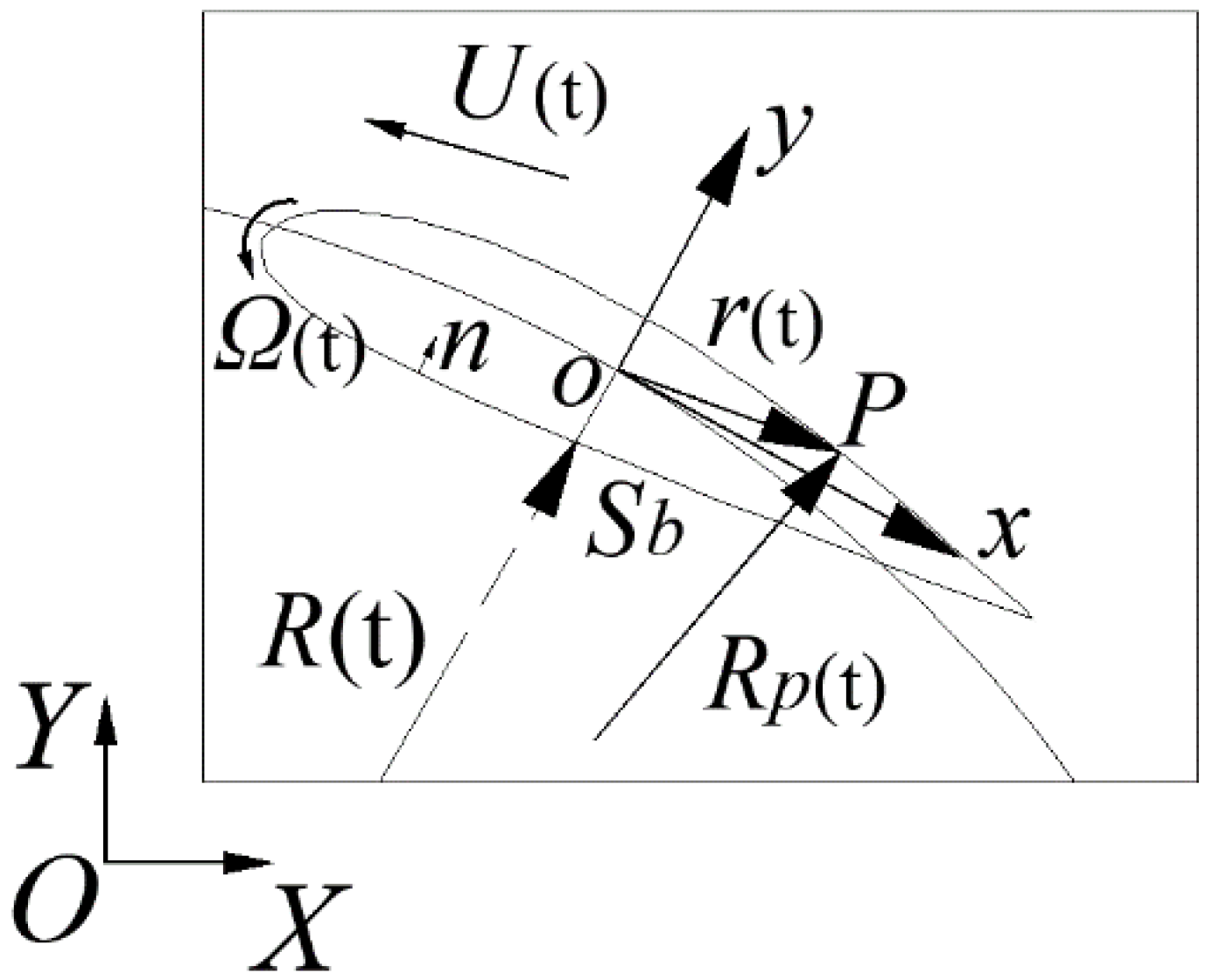
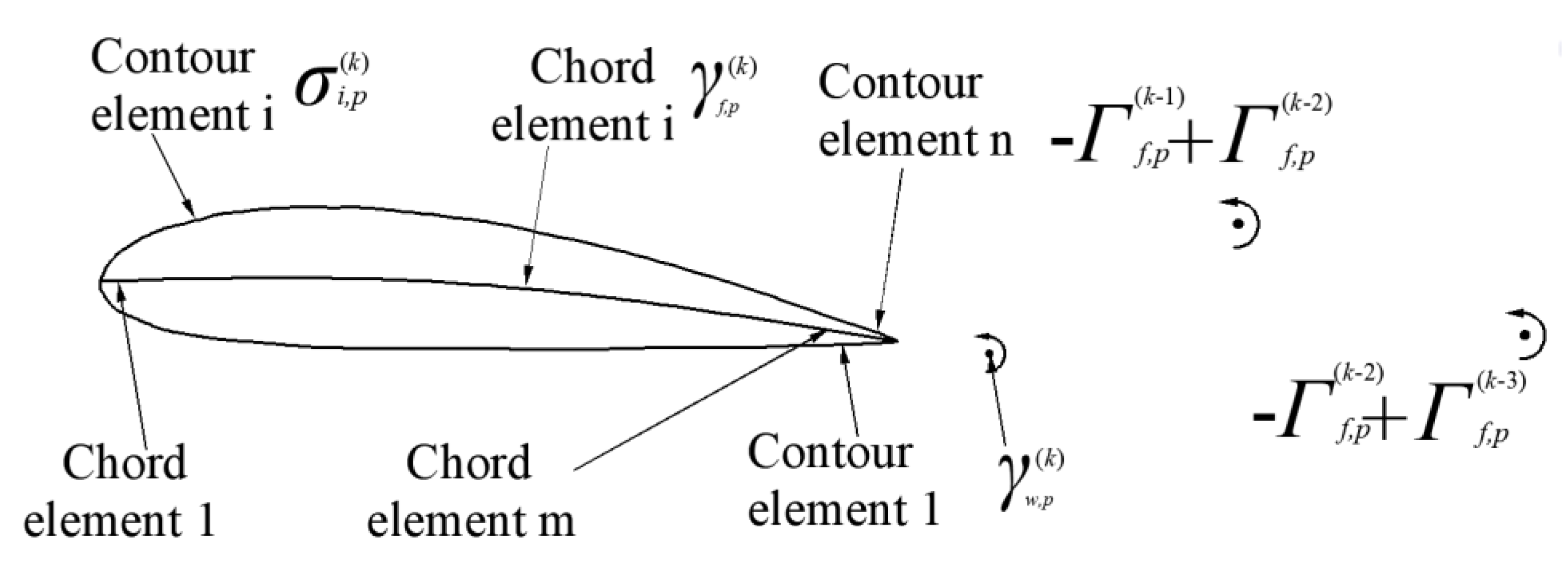
The forces and circulation of the blade can be calculated accurately by the vortex panel method, which was confirmed in the published papers [18,20]. The finite vortex method is one type of the vortex panel method [19,40]. A schematic of the vertical axis turbine in the reference coordinate is shown in Figure 1. A close-up view of the blade is shown in Figure 2. The motion of the blade can be described by the translational velocity U and angular velocity Ω relative to the local coordinate system o. The inflow velocity is VA. There are N sources and sinks distributed on the surface of the blade and a linear vortex lineγon the chord line. The schematic diagram is shown in Figure 3.
The total velocity potential ϕ satisfies the Laplace equation in the global coordinate system, as shown in Equation (1) below:
2 ϕ ( X , Y , t ) = 0
The surface of the blade satisfies no through-flow boundary condition, as shown in Equation (2), where r is the vector from the local coordinate system o to the blade surface, nb is the unit normal vector that points to the interior of the blade, the symbol Sb denotes the surface of the blade.
ϕ n | S b = ( U V A + Ω × r ) · n b
The symbol p is the field point; in the far-field, the induced velocity potential φ satisfies lim p φ = 0 . At the initial time t = 0, the induced velocity potential satisfies the relationship shown in Equation (3):
φ ( p , 0 ) = 0
Some experimental studies [41,42] on the flow field showed that there is a finite pressure difference at the trailing edge under the unsteady conditions, which makes the streamline roll-up. In order to solve the stall condition at a high angle of attack, the improved Kutta condition set up a finite pressure difference at the trailing edge. Therefore it is called the finite vortex method [19,43]. The subscripts u and d represent the up and downsides of the trailing edge. The improved Kutta condition of the finite vortex model is shown in Equation (4):
p u p d = Δ p
In order to determine the value of this pressure difference, set a parameter l to satisfy the relation: Δ p = p u p d = l ρ γ w ( k ) , where γ w ( k ) is the circulation of the vortex shedding at the step k. By adjusting the value of l, the lift coefficient of numerical results would be kept consistent with the lift coefficient obtained by the experiment at different angles of attack [19]. The value of l is close to 0 at the small angle of attack, which indicates that the computational error of conventional Kutta condition (pressure difference at trailing edge is equal to 0) is not large at the small angle of attack. With the increase of angle of attack, the absolute value of l is also increasing, which indicates that the pressure difference of the trailing edge is also increasing gradually. Therefore, due to the existence of the correction factor l and the finite value of pressure difference at the trailing edge, the aerodynamic loads calculated by the finite vortex method can still be consistent with the experimental data at a high angle of attack. It also means that the finite vortex method can be more accurate than the conventional vortex panel method in the case of a high angle of attack.
According to the unsteady Bernoulli equation (as shown in Equation (5)), the pressure in the flow field is:
p p ρ = φ t + ( U V A + Ω × r ) · φ 1 2 ( φ ) 2
As the up and downsides of the trailing edge are very close to each other, the vector of the trailing edge can be written as Equation (6):
r u r d 1 2 ( r u + r d ) = r T E
Therefore, after the linearization, the Kutta condition can be rewritten as Equation (7):
( φ u φ d ) t = Γ f t = ( U V A + Ω × r T E ) · ( φ u φ d ) + 1 2 ( φ d φ u ) · ( φ d + φ u ) Δ p ρ = ( U V A + Ω × r T E V T E ) · ( φ u φ d ) Δ p ρ
where mean disturbance velocity vector VTE of the trailing edge is shown in Equation (8):
V T E = 1 2 ( φ u + φ d )
According to Kelvin’s theorem, the total circulation does not change with time under the potential flow theory; in other words, the sum of circulation of the bound vortex (Γf) and free vortex (Γw) does not change with time. Hence, there is Equation (9). At different azimuthal angles, the lift and circulation of the airfoil will change. In each time step, the circulation variation of the bound vortex and that of the free vortex are equal in value, but the sign of them are opposite. It can be expressed as Equation (10). Here, the subscript f represents the circulation of the foil, and the subscript w represents the vortex in the wake, the superscript k represents the time step. Combining Equation (10) with Kelvin’s theorem (Equation (9)), Equation (11) is obtained. Then, the circulation of the vortex shedding γ can be calculated by inserting Equation (11) into Equation (7) above. Moreover, the γ obtained here is exactly the circulation that will be discretized into the vortex particles. The detailed process is shown in the references [18,19,20].
d Γ t o t a l d t = d ( Γ f + Γ w ) d t = 0
Γ f ( k ) Γ f ( k 1 ) = γ w ( k )
d Γ f d t = d Γ w d t = Γ f ( k ) Γ f ( k 1 ) Δ t = γ w ( k ) Δ t

3.2. Vortex Particle Method

The circulation of the shedding vortex is calculated by the finite vortex method in the potential flow. Then, it will be discretized into a vortex particle swarm to calculate the wake evolution in viscous flow. The vortex particle program is divided into six subsections as follows, and the definition of symbols in each equation is only applicable to the relevant subsection.

3.2.1. Discretization of the Circulation

In this paper, the Vatistas model [44] is used as the vortex core model, which is a common smoothing function to remove the singularity, and it is also similar to the Gaussian smoothing function. The Vatistas model also has been applied in the research of a HAWT wake [13]. The regularization function K is shown in Equation (12): (where ρ = r / r c and r c is the radius of the vortex core):
K ( ρ ) = 1 π ( ρ 4 + 1 ) 3 2
Which satisfies the normalization condition, as shown in Equation (13):
2 π K ( ρ ) ρ d ρ = 1
The function of vorticity distribution is shown in Equation (14):
ω ( r ) = Γ r c 2 K ( ρ ) = Γ r c 4 π ( r 4 + r c 4 ) 3 2

3.2.2. Vorticity Transport Equation

The vortex particle method is a viscous method, the governing equation as follows is the vorticity transport equation, which is obtained by taking the curl of the incompressible NS equation, as shown in Equation (15):
d ω d t = ( ω · ) V + ν 2 ω
It is worth mentioning that in the two-dimensional case, there is no stretching term, so the control equation is simplified as Equation (16):
d ω d t = ν 2 ω
It can be seen that the governing equation of the vortex particle method in the two-dimensional case is much simpler than the NS equation of the grid-based method.

3.2.3. The Calculation of the Velocity of Vortex Particles

The convection of the vortex particles is calculated by the Biot–Savart Equation. The induced velocity of the Vatistas model in Equation (17):
V = Γ 2 π × r r 4 + r c 4
It can be seen that Equation (17) is very close to the induced velocity equation of a two-dimensional singular vortex, as shown in Equation (18):
V = Γ 2 π r
In this paper, the fast multipole method (FMM) [45] is introduced to accelerate the calculation of the induced velocity of the vortex particles. Here, the induced velocity can be written in the form of induced velocity potential φ, z 0 is the target position, z is the position of the vortex particle, and z c is the centroid position of the block. The derivation of the Green function is shown in Equation (19):
G ( z 0 , z ) = 1 2 π log ( z 0 z ) = 1 2 π [ log ( z 0 z c ) + log ( 1 z z c z 0 z c ) ]
Applying the Taylor series expansion log ( 1 ξ ) = k = 1 ξ k k to the second logarithmic term on the right side of Equation (19), Equation (19) can be transformed into the following form (Equation (20)):
G ( z 0 , z ) = 1 2 π k = 0 O k ( z 0 z c ) I k ( z z c )
There are two auxiliary functions ( I k ( z z c ) and O k ( z 0 z c ) ) defined here:
I k ( z z c ) = ( z z c ) k k ! ,   for   k     0
O k ( z 0 z c ) = ( k 1 ) ! ( z 0 z c ) k ,   for   k   1 ;   and   O 0 ( z 0 z c ) = log ( z 0 z c )
The final expression of velocity potential φ (Equation (23)) and accuracy criterion of order p (Equation (24)) can be written as follows: (Γ is the circulation of each vortex particle, p is the order of Taylor expansion, N is the number of the vortex particles, the error ε is set to 10−5 in this paper, R is the diagonal length of the block. Moreover, the black dot here represents the scalar multiplication.)
ϕ = 1 2 π k = 1 p { ( k 1 ) ! ( z 0 z c ) k · [ 0 N ( z z c ) k · Γ k ! ] } 1 2 π ln ( z 0 z c ) · [ 0 N Γ ]
p = ln [ ε · ( 2 π ) · ( 1 R | z 0 z c | ) ] / ln ( R | z 0 z c | ) 1
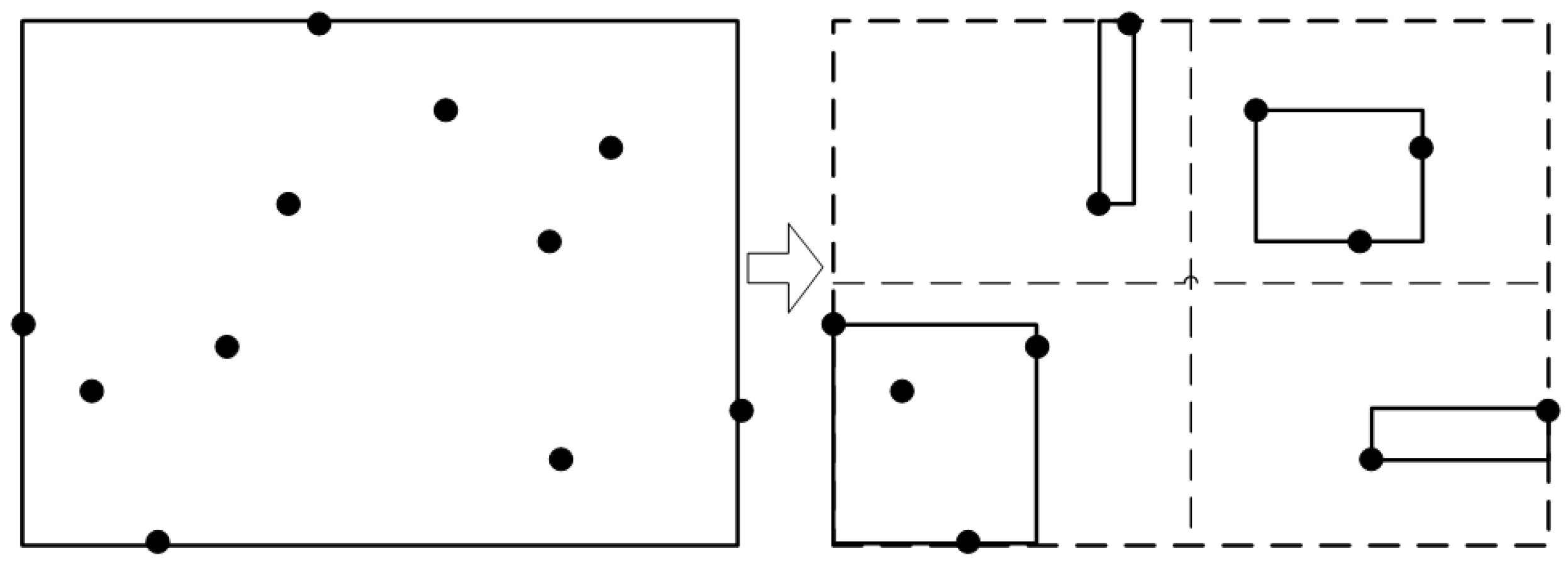
There is an error criterion to judge whether the FMM can replace the direct calculation. The order of the FMM program is NlogN; by contrast, the order of the direct calculation method is N 2 [46,47]. In the FMM program, it is necessary to allocate the whole vortex particles into a tree structure and store them in the leaf nodes of the tree structure. The schematic diagram of the fast multipole method is shown in Figure 4.

3.2.4. The Calculation of the Vorticity of Vortex Particles

When the position of the vortex particles is updated, it is necessary to update the vorticity of the vortex particles. There are two common methods to simulate the viscous dissipation. One is called the random walk algorithm; the other is the particle strength exchange method (PSE). In this paper, the latter method (PSE) is used. In order to calculate the vorticity dissipation term, a transformation Equation (25) is introduced here to transform the second derivative form of the NS equation into the integral or summation form [48] (The symbol f in the following equation represents the function of vorticity ω).
2 f ( x ) = 2 σ 2 [ f ( y ) f ( x ) ] η σ ( x y ) d y
where:
η σ ( r ) = 1 σ 2 η ( r σ )   and   η ( ρ ) = 1 ρ d K ( ρ ) d ρ
The governing equation is transformed into the summation form (Equation (27)):
d ω P d t = 12 υ π q σ 4 r p q 2 ( Γ q Γ p ) ( r p q 4 + σ 4 ) 5 / 2
Subscript p represents the target point, q is the vortex particles, and the symbol σ is the radius of the vortex particle.

3.2.5. The Calculation of the Turbulent Viscosity Coefficient

It is worth mentioning that the viscosity coefficient ν in Equation (27) includes physical viscosity and turbulent viscosity, and the turbulent viscosity is often larger than the physical viscosity. As mentioned in Section 2, in the two-dimensional simulation, no matter what numerical method is used, the three-dimensional effect correction model is needed. However, the turbulence model is still necessary, so here is a brief introduction. The large eddy simulation (LES) in the Lagrangian frame [13] is introduced to calculate the turbulent viscosity in the flow field. The method proposed by Mansfield et al. [49] in Lagrangian large eddy simulation can establish the relationship between filter scale and vortex particle scale. The smoothing function K is related to the particle filter G; the relationship is shown in Equation (28):
G Δ ( r ) = K Δ / c ( r )
where c is a constant, the filtering scale ∆ and the radios of the vortex particle σ satisfy the relationship: Δ = c σ . The particle filter and circular filter meet the energy conservation equation in the wavenumber domain. By numerical calculation, the solution c = Δ / σ = 2.83 can be obtained. More numerical processes can be found in the work of Liu [13].
When the filtering scale ∆ is obtained, the turbulent viscosity can be calculated from the following Equation (29) according to the LES Smagorinsky model [50].
ν s g s = ( c Δ ) 2 ω ¯ · ω ¯ 1 / 2

3.2.6. The Redistribution of the Vortex Particles

In order to ensure the convergence of the vortex particle method, a redistribution algorithm is in need [51]. Especially when the distance between particles is too large, the redistribution of particles can ensure a certain overlap rate between particles. There are some interpolation stencils, which distribute the vortex particle on the surrounding nodes with different weights. In this paper, the third-order interpolation function (Equation (30)) is used
Λ 2 ( λ ) = { 1 λ 2 , 0 λ < 0.5 ( λ 2 3 λ + 2 ) / 2 , 0.5 λ < 1.5 0 , others
Λ 2 D ( x h , y h ) = Λ ( x h ) Λ ( y h )
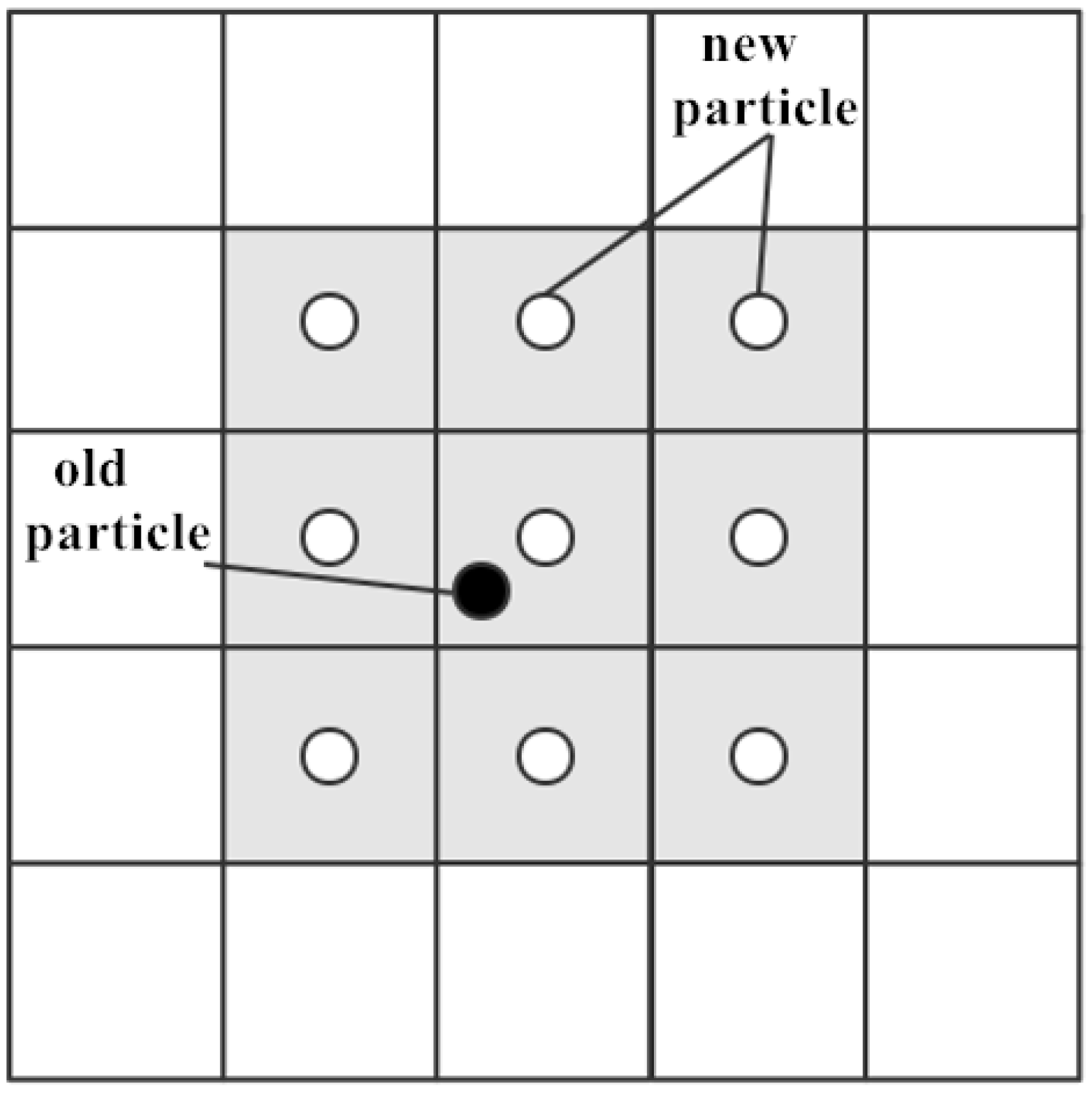
where λ = x / h , x is the distance from the center of mesh to the old particles, h is the mesh size. Each old vortex particle will be replaced by nine new particles on the surrounding mesh nodes, as shown in Figure 5.

3.3. Discrete Parameters and Relevant Convergence Criteria

In this paper, the PIV experiment [10] is used as the benchmark test case for validation. The experimental parameters are shown in the Table 2 below.
The relevant experience of the discrete parameters and the corresponding convergence criteria will be introduced one by one:
The finite vortex method is not a time-consuming algorithm, and in order to ensure convergence accuracy, in this paper, there are 200 discrete elements on the blade surface. The time step of the finite vortex method is the time for 1° rotation, and it is a common discrete scale, which is proved by another paper [52]. The numerical parameters in the finite vortex method are conservative, and the accuracy of the program also has been verified by the previously published paper [18].
The diameter of the vortex core in the vortex particle method should be slightly larger than the chord length of VAT. In this case, the diameter of the vortex core is 1.2 times the chord length. This experience is also similar to the selection of the smooth length in the actuator line model [53].
It is worth mentioning that the vortex particle method is a mesh-free method. Therefore, there is no need to verify the independence of mesh size, and it is diffusion free in theory [54]. As long as the number of the vortex particles is enough, the wake evolution could be accurately simulated. The redistribution program in the vortex particle method redistributes each vortex particle to nine new particles through the interpolation function, which satisfies the conservation of the circulation from the zero-order moment to the second-order moment. In this way, the number of the vortex particles will be enough at the place where the vorticity is high, and the vortex particle methods will be automatically adaptive and will concentrate on the regions of physical interest [55]. Since the number of the vortex particles is adjusted adaptively by the redistribution program, the initial number of the vortex particles has little impact on the simulation of the wake-field. Therefore, it is not necessary to verify the independence of the number of vortex particles. In general, the numerical viscosity of the grid-based method will produce a big diffusive error in high Reynolds number. In contrast, the redistribution program does not bring discernible numerical dissipation. Redistribute the vortex particles in 2D simulations, which shows substantially lower errors than infrequent redistribution [46]. The redistribution program could provide a potential solution for the accurate simulation of the vorticity [56]. It can be seen that the redistribution is of great significance to the convergence of the vortex particle method.
The mesh size of the redistribution program is h = 0.0025 m. In order to ensure that there is a certain overlap rate between adjacent particles, the convergence criterion required that the vortex particle radius should be larger than the mesh size [46]. Hence, the radius of the vortex particle is r0 = 0.0033 m.
According to the equation πD/c ≈17.4, the circumference is 17.4 times of the chord length. Therefore, it is set to discharge the vortex 18 times in one rotation period. That is 360°/18 = 20°; the time interval of the vortex shedding is the time for 20° rotation. The corresponding time step here is 0.0028 s. According to the stability criterion [46], the time step should be less than the reciprocal of the maximum vorticity. In this view, the maximum allowable vorticity under the convergence criterion should be 1/0.0028 s ≈350 s−1. Although the value of vorticity changes with time due to the redistribution, the magnitude of vorticity is within ten in this case, which obviously satisfies the stability criterion.
It can be seen from the benchmark experiment that the blocking effect can be ignored. Therefore, the wake evolution in this paper is simulated under unbounded conditions, and the blocking effect has not been involved. In the vortex particle method, there is no need to set special boundary conditions for unbounded flow. This is a feature different from the grid method.

3.4. The Three-Dimensional Effect Correction Model of Wake

This new correction model is a projection function along the streamwise direction to correct the three-dimensional effect of the velocity field. As we all know, the three-dimensional effect of the wake is that the third dimension will accelerate the recovery of the velocity deficit in the two-dimensional wake. By multiplying the two-dimensional velocity deficit field with a projection function, the influence of the third dimension on the velocity recovery can be equivalent.
The correction process is based on some empirical fitting functions of the VAWT wake. According to the analysis of PIV experiment results [57], the velocity deficit of the wake can be fitted into the power-law function of the downstream position X: Δ U U 0 = c 1 ( X X t ) c 2 + c 3 , where Xt is the downstream transition location which is related to the dynamic solidity σ D , and it can be obtained by this equation: X t r a n s i t i o n = D ( 4.78 4.93 σ D ) , where D is the diameter of the VAWT. These three coefficients, c1 c2 c3, are the empirical fitting coefficients which are influenced by solidity and tip speed ratio. Moreover, this form of the power-law function is also applicable to the HAWT wake and the two-dimensional or three-dimensional bluff body wake [57].
Therefore, the process of the three-dimensional effect correction proposed in this paper is based on the three-dimensional velocity distribution functions summarized by the previous study [57]. Then, we divided these three-dimensional velocity distribution functions by a two-dimensional velocity distribution function, and the proportion obtained by the division is the projection coefficient from the two-dimensional to the three-dimensional, which is exactly what we want to correct the three-dimensional effect of the wake-field. Finally, the two-dimensional velocity field is multiplied by the projection coefficient along the streamwise direction, and the two-dimensional simulation results considering the three-dimensional effect correction can be used in the preliminary array design.
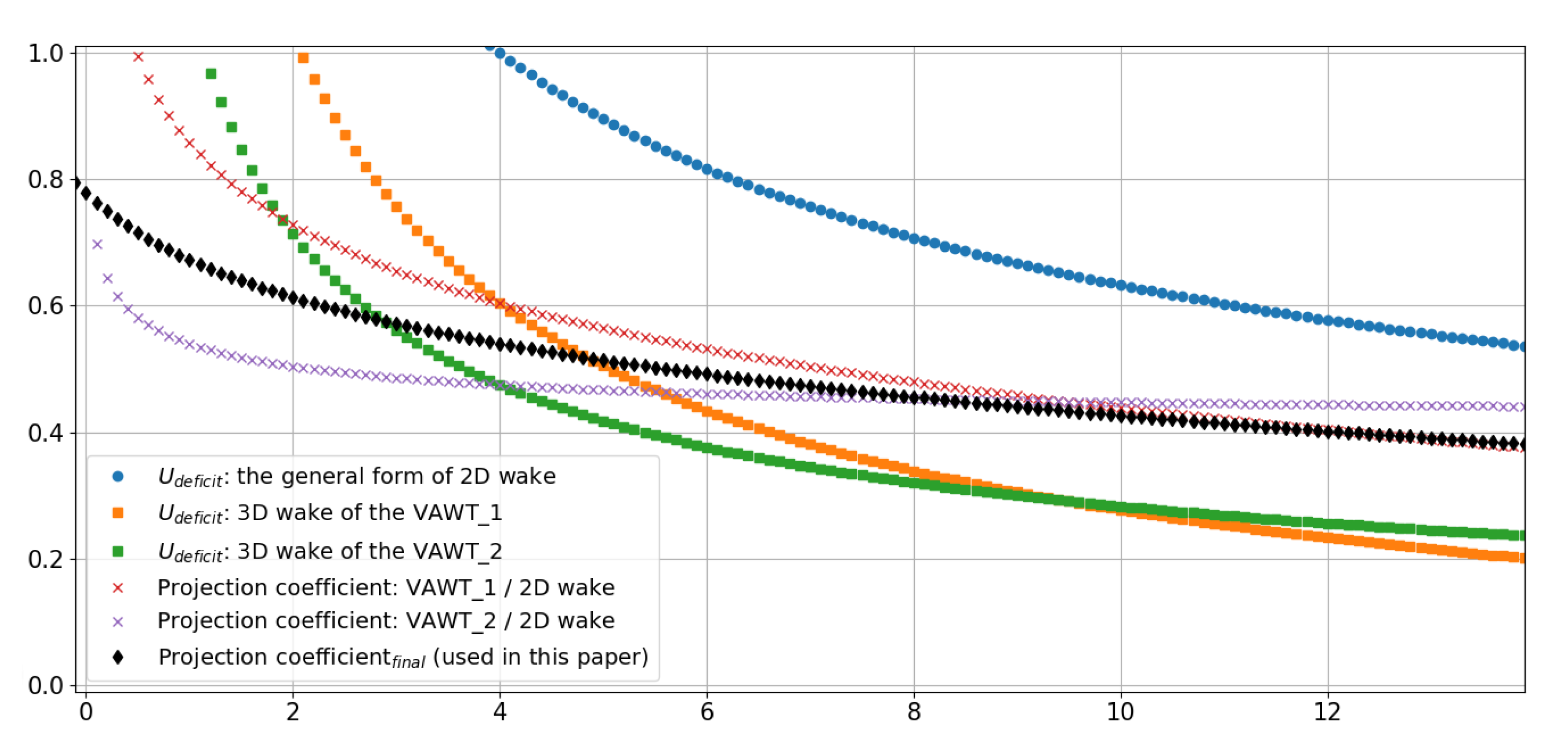
In order to get the appropriate three-dimensional velocity distribution function which is close to the benchmark case in this paper, two models are selected from the previous study [57] because the parameters of these two models are relatively close to that of the benchmark case, and they were marked as VAWT_1 and VAWT_2, respectively. The velocity distribution of the three-dimensional wake models (VAWT_1 and VAWT_2) and the general form of the velocity distribution of the two-dimensional wake model are described in Table 3 below.
It can be seen from these functions that the power-law exponent of the two-dimensional wake is −0.5, which is significantly larger than that of the other two three-dimensional wake models (−0.684 and −0.622). That is to say, due to the three-dimensional effect, the decay rate of the two-dimensional wake model is slower than that of the three-dimensional model.
In addition, it should be noted that the two models (VAWT_1 and VAWT_2) selected here are relatively close to the model in this paper; this can be seen in Figure 25 in the reference [57] that there is little difference in the power function between different VAT conditions. Therefore, there is no need to be too concerned about whether the selection of the experimental model is completely consistent with the validation model used in this paper.
In Figure 6, the curves formed by the square symbol (■) represent the power functions of the three-dimensional wake models (VAWT_1 and VAWT_2), the curve formed by the closed circle symbol (●) represents the general form of the power function of the two-dimensional wake model. The functions of these three curves are described above. Then, these two power functions of the three-dimensional wake models (symbol ■) are divided by the power function of the two-dimensional wake model (symbol ●), and the ratio functions obtained (symbol ×) are the correction coefficient along the streamwise, which could be used to correct the velocity deficit from the two-dimensional to the three-dimensional.
There are two other considerations: The first is to eliminate the unreasonable situation that the ratio is much greater than one within one diameter. Second, considering that the three-dimensional effect will make the power coefficient of VAT smaller than that of the two-dimensional model [33], and there is a positive correlation between the power coefficient and the velocity deficit, that is to say, the velocity deficit and power coefficient of the three-dimensional model are smaller than those of the two-dimensional model. Hence, the correction coefficient should be slightly less than 1 in the near field. Based on these two considerations, combine the two ratio functions (symbol ×), what we get is the empirical coefficient (symbol♦) related to the streamwise position, and the combined function (symbol♦) can be approximately regarded as the final three-dimensional effect projection function which is used in this paper.
It can be found that the curve is a function of the distance along the streamwise direction; by multiplying the two-dimensional velocity field with the projection coefficient (symbol♦) along the streamwise direction, the wake-field corrected by the three-dimensional effect can be obtained. Moreover, this is the whole process of the three-dimensional effect correction for two-dimensional wake simulation in this paper.
In this paper, the power-law function is proposed to correct the three-dimensional effect, which will be a universal idea. Not only the wake of HAWT and VAWT but also the wake of the two-dimensional or three-dimensional bluff body conform to the form of the power-law function [57,58]. Moreover, the two-dimensional Gaussian power function was also used as the basic wake model for array layout design [35,59]. Even if the influence of the boundary layer on the wake is considered, the velocity distribution function could also be fitted into the form of the power-law function [60].
In fact, the correction model is widely used in real engineering practice to simplify the simulation, and it can be equivalent to the effect of some complicated turbulence details, such as dynamic stall and complex turbulent inflow conditions. Especially for the array design, the first-order approximation of the velocity distribution is enough to meet the demand, and the three-dimensional effect correction of the two-dimensional wake simulation is a good choice. The correction model proposed in this paper is derived from the power-law function of velocity distribution, which could make the numerical results in good agreement with the three-dimensional results. The validation of this numerical method is shown in Section 4.

4. Validation and Discussion

In order to verify the reliability of the new numerical method proposed in this paper, a PIV experiment is selected to compare with the simulation results. The parameters of this PIV experiment have been described in detail in Table 2 in Section 3.3.
The comparison results are shown in Figure 7. Relatively speaking, the average velocity profiles calculated by the proposed method match well with the PIV experimental data [10]. At least for the preliminary array design, it is an encouraging result to achieve at least first-order accuracy in the two-dimensional wake simulation. It also proves that the two-dimensional numerical method with a reasonable three-dimensional correction is an acceptable and practicable approach that can make the wake simulation faster and the array design easier. In Figure 8, the rotation direction of the VAWT is counterclockwise. According to the analysis of velocity distribution of a VAWT wake, the peak value of velocity deficit is found not on the centerline. This asymmetry can be seen in the velocity field (Figure 8).
It needs to be clarified here, in the preliminary array design, only the time-averaged velocity field needs to be considered, and the unsteady flow details can be ignored. In addition, since the validation data of the reference is time-averaged, and the benchmark test case did not provide the transient experimental data at different times. In order to keep consistent with the benchmark test case, the time-averaged velocity field was used in this paper.
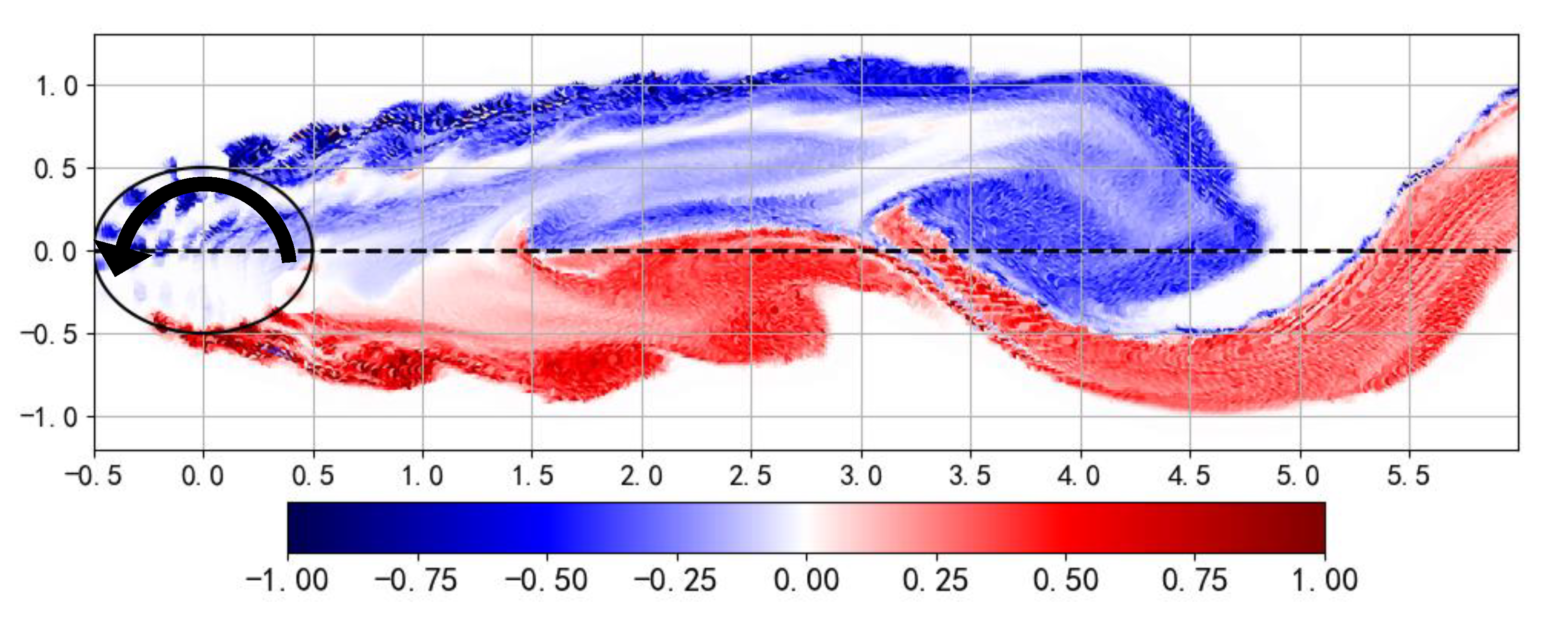
In the vorticity field (Figure 9), due to the velocity deficit caused by the turbine and the conservation of momentum, the wake vortex will expand in the near field, and the expansion phenomenon of the stream tube in the numerical simulation is similar to the flow field observed by another PIV experiment [5]. It can also be seen that there is a skewness in the distribution of the wake vortex. According to the Magnus effect, a lateral force perpendicular to the inflow direction will be produced on a spinning object. In addition, according to Newton’s third law, the forces acting on the turbine and the forces acting on the flow field belong to action and reaction. In this case, the VAWT rotates counterclockwise and is subjected to a downward lateral force. Therefore, the wake is subjected to the upward force and will move upward. The similar phenomena of the wake skewness have also been found in some other VAT wake experiments [8,11]. It can be seen that there is a skewness in the VAT wake caused by the Magnus effect. Moreover, the faster the rotation, the greater the wake skewness. The explanation that wake skewness is related to the Magnus effect can also be found in other studies [5,9,61]. However, from the micro point of view, the generation of the wake skewness is caused by the wind-blade interaction, and it can also be explained from the macro point of view that the wake skewness is caused by the Magnus effect. Both explanations are correct. By comparison, there is usually no skewness in the HAWT wake, this consideration will make the array layout of VAT different from that of HAT. Moreover, more suggestions can be provided for the array arrangement of VATs, such as, the arrangement distance for the downstream VAT should be different considering the rotation direction of the upstream VAT.
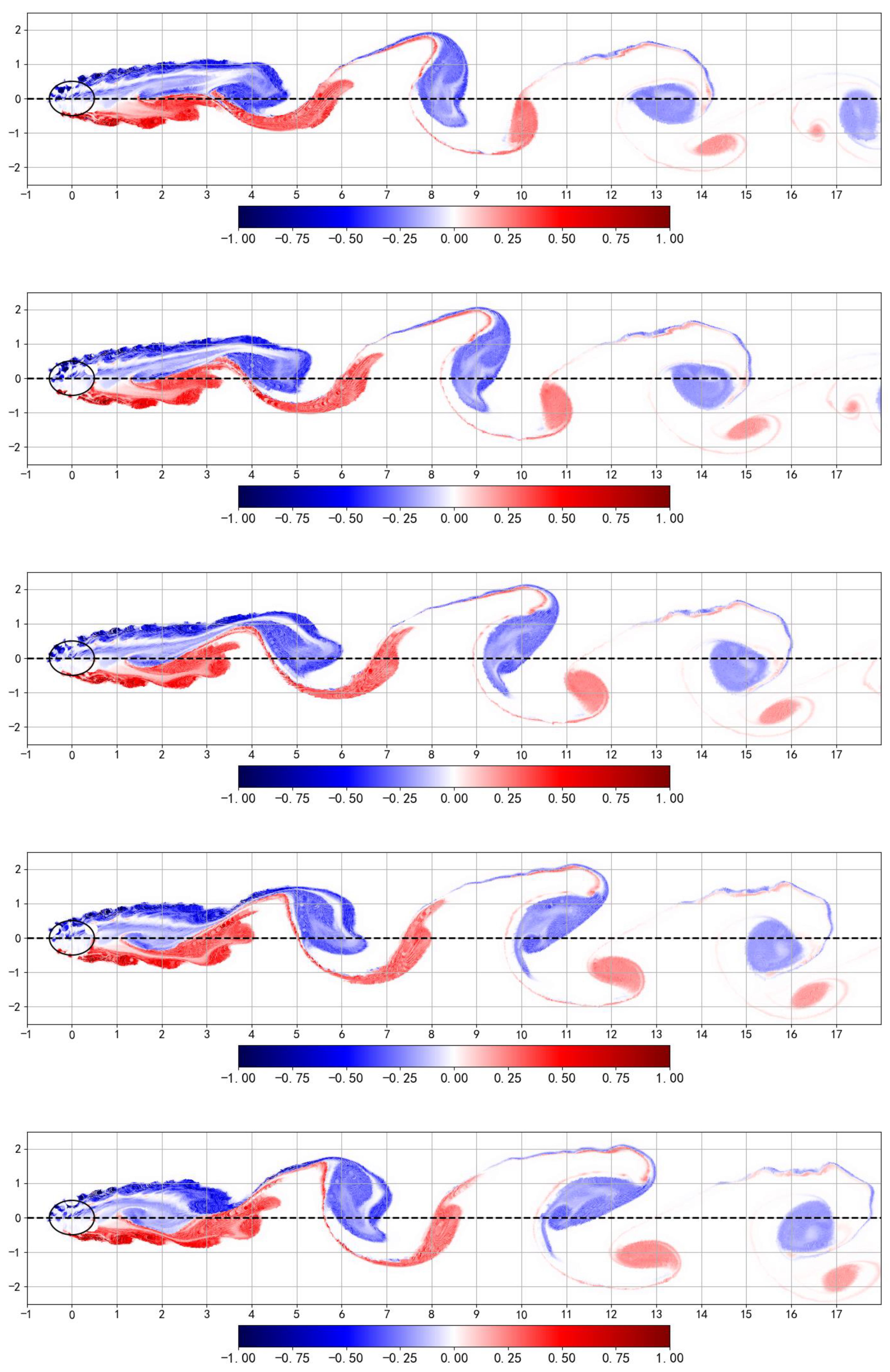
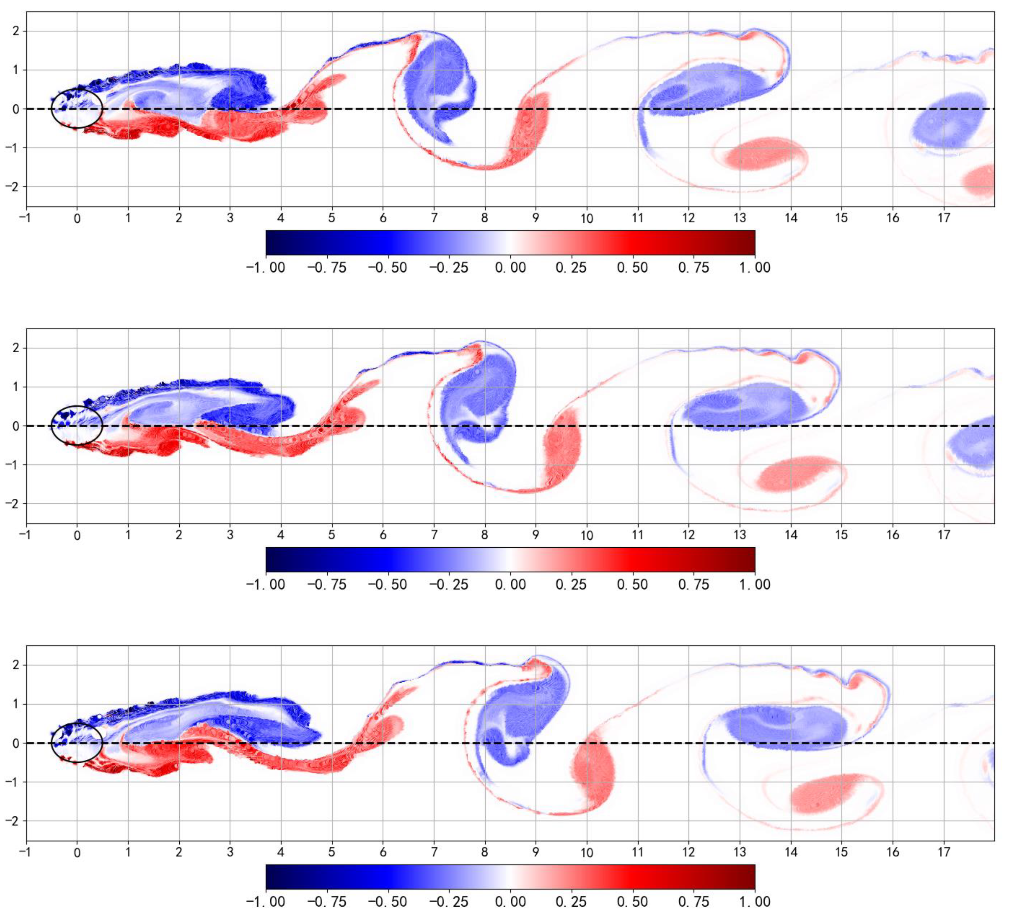
There is another interesting phenomenon in the far wake in Figure 10. It can be seen from the following eight moments in one period (the period here is not the rotation period, but the period of the vortex street oscillation), due to the complex evolution, the vortex pairs in the far-field are similar to the Karman vortex street in the flow around a cylinder. This characteristic can also be found in another reference [62]. The similar wake evolution will occur in the far-field of a HAT wake as well [39]. It is still unknown whether this complex evolution is similar to the meandering of the HAWT wake. However, at least, this interesting phenomenon in these eight images shown here can lead to a new research direction in the future.
It is also worth mentioning that the vorticity of the vortex particle swarm is different at each time step, and the redistribution program makes the number and vorticity of the vortex particles change all the time. Therefore, the peak value of the vorticity field (ωmax) and the range of the color bar (ω) also change at each time step. In order to unify the color bar for observation, the vorticity field (Figure 9 and Figure 10) is normalized by the maximum vorticity at that moment. The color bars of the wake-field are represented by the dimensionless vorticity (ω/ωmax). In general, although the redistribution program makes the range of vorticity field change all the time, for the vortex particle method, the whole field still satisfies the conservation condition, so it may not be necessary to pay too much attention to the absolute value of the vorticity at each moment.
However, the purpose of this paper is to propose a fast simulation method for the VAWT wake, so the complex wake evolution phenomenon will not be discussed in depth. The simulation results are calculated by the code written by the authors, and there is no commercial software to use this numerical method so far. In terms of the calculation efficiency of the algorithm, the vortex particle method takes less than 2 h on 4-core CPUs, and the number of the vortex particles is about a hundred thousand, when the focus is only on the flow field within 10D, as we all know, the calculation cost here is much less than that of the grid-based method.

5. Conclusions

In this paper, by combining the finite vortex method and the vortex particle method, a fast and relatively accurate two-dimensional numerical method is proposed to simulate the wake-field of the vertical axis wind turbine. Based on the power-law function of velocity distribution, a new correction model is proposed to correct the three-dimensional effect of the VAWT wake. Then, the feasibility of the numerical method is preliminarily verified by the PIV experiment. Finally, according to the flow field analysis, the skewness of the VAWT wake is discussed. In the far-field, the VAWT wake evolves into the Karman vortex street, which is similar to the flow around a cylinder.
Although the published experiments on the VAT wake, which can be used for the verification, are relatively limited, however, the numerical method proposed in this paper is feasible in theory and has been preliminarily verified. It has been proven that this new method can simulate the velocity distribution quickly and relatively accurately. The first-order approximation can be achieved by this two-dimensional numerical method, which meets the requirement for efficiency in the preliminary array design. In the future, with more experimental data published, the numerical method proposed in this paper will be systematically studied and improved. Nevertheless, we believe that it can be a promising approach to make the VAWT array design easier and more reasonable.

Author Contributions

Z.Y.: Investigation, methodology, writing the original draft preparation; J.J.: methodology, supervision; J.Z.: methodology, supervision; Q.S.: methodology; K.S.: methodology, validation; X.Z.: methodology; R.J.: Writing—review and editing. All authors have read and agreed to the published version of the manuscript.

Funding

This work was supported by the National Natural Science Foundation of China (No. 51879064, No. U1706227, No. 51979062).

Conflicts of Interest

The authors declare no conflict of interest.

References

  1. Wiser, R.; Jenni, K.; Seel, J.; Baker, E.; Hand, M.; Lantz, E.; Smith, A. Expert elicitation survey on future wind energy costs. Nat. Energy 2016, 1, 16135. [Google Scholar] [CrossRef]
  2. Paraschivoiu, I. Wind Turbine Design: With Emphasis on Darrieus Concept; Presses Inter Polytechnique: Montréal, QC, Canada, 2002. [Google Scholar]
  3. Araya, D.B.; Craig, A.E.; Kinzel, M.; Dabiri, J.O. Low-order modeling of wind farm aerodynamics using leaky Rankine bodies. J. Renew. Sustain. Energy 2014, 6, 063118. [Google Scholar] [CrossRef] [Green Version]
  4. Dabiri, J.O. Potential order-of-magnitude enhancement of wind farm power density via counter-rotating vertical-axis wind turbine arrays. J. Renew. Sustain. Energy 2011, 3, 043104. [Google Scholar] [CrossRef] [Green Version]
  5. Tescione, G.; Ragni, D.; He, C.; Ferreira, C.S.; Van Bussel, G. Near wake flow analysis of a vertical axis wind turbine by stereoscopic particle image velocimetry. Renew. Energy 2014, 70, 47–61. [Google Scholar] [CrossRef]
  6. Somoano, M.; Huera-Huarte, F. Flow dynamics inside the rotor of a three straight bladed cross-flow turbine. Appl. Ocean Res. 2017, 69, 138–147. [Google Scholar] [CrossRef]
  7. Araya, D.B.; Dabiri, J.O. A comparison of wake measurements in motor-driven and flow-driven turbine experiments. Exp. Fluids 2015, 56, 150. [Google Scholar] [CrossRef]
  8. Peng, H.; Lam, H.-F.; Lee, C. Investigation into the wake aerodynamics of a five-straight-bladed vertical axis wind turbine by wind tunnel tests. J. Wind. Eng. Ind. Aerodyn. 2016, 155, 23–35. [Google Scholar] [CrossRef]
  9. Ouro, P.; Runge, S.; Luo, Q.; Stoesser, T. Three-dimensionality of the wake recovery behind a vertical axis turbine. Renew. Energy 2019, 133, 1066–1077. [Google Scholar] [CrossRef] [Green Version]
  10. Rolin, V.F.-C.; Porté-Agel, F. Experimental investigation of vertical-axis wind-turbine wakes in boundary layer flow. Renew. Energy 2018, 118, 1–13. [Google Scholar] [CrossRef]
  11. Rolin, V.; Porté-Agel, F. Wind-tunnel study of the wake behind a vertical axis wind turbine in a boundary layer flow using stereoscopic particle image velocimetry. J. Phys. Conf. Ser. 2015, 625, 012012. [Google Scholar] [CrossRef] [Green Version]
  12. Ryan, K.J.; Coletti, F.; Elkins, C.J.; Dabiri, J.O.; Eaton, J.K. Three-dimensional flow field around and downstream of a subscale model rotating vertical axis wind turbine. Exp. Fluids 2016, 57, 38. [Google Scholar] [CrossRef]
  13. Liu, W.; Liu, W.; Zhang, L.; Sheng, Q.; Zhou, B. A numerical model for wind turbine wakes based on the vortex filament method. Energy 2018, 157, 561–570. [Google Scholar] [CrossRef]
  14. Bachant, P.; Wosnik, M. Reynolds Number Dependence of Cross-Flow Turbine Performance and Near-Wake Characteristics. APS, A13-006. 2014. Available online: http://vtechworks.lib.vt.edu/handle/10919/49210 (accessed on 25 October 2020).
  15. Chamorro, L.P.; Arndt, R.E.A.; Sotiropoulos, F. Reynolds number dependence of turbulence statistics in the wake of wind turbines. Wind. Energy 2012, 15, 733–742. [Google Scholar] [CrossRef]
  16. Polagye, B.; Cavagnaro, R.; Niblick, A.; Hall, T.; Thomson, J.; Aliseda, A. Cross-flow turbine performance and wake characterization. In Proceedings of the 1st Marine Energy Technology Symposium (METS13), Washington, DC, USA, 10–11 April 2013. [Google Scholar]
  17. Du, L.; Ingram, G.; Dominy, R.G. A review of H-Darrieus wind turbine aerodynamic research. Proc. Inst. Mech. Eng. Part C J. Mech. Eng. Sci. 2019, 233, 7590–7616. [Google Scholar] [CrossRef] [Green Version]
  18. Wang, L.; Zhang, L.; Zeng, N. A potential flow 2-D vortex panel model: Applications to vertical axis straight blade tidal turbine. Energy Convers. Manag. 2007, 48, 454–461. [Google Scholar] [CrossRef]
  19. Jiang, J.; Ju, Q.; Yang, Y. Finite Element Vortex Method for Hydrodynamic Analysis of Vertical Axis Cycloidal Tidal Turbine. J. Coast. Res. 2019, 93, 988–997. [Google Scholar] [CrossRef]
  20. Li, G.; Chen, Q.; Gu, H. An Unsteady Boundary Element Model for Hydrodynamic Performance of a Multi-Blade Vertical-Axis Tidal Turbine. Water 2018, 10, 1413. [Google Scholar] [CrossRef] [Green Version]
  21. Zou, F.; Riziotis, V.A.; Voutsinas, S.G.; Wang, J. Analysis of vortex-induced and stall-induced vibrations at standstill conditions using a free wake aerodynamic code. Wind. Energy 2014, 18, 2145–2169. [Google Scholar] [CrossRef]
  22. Abedi, H.; Davidson, L.; Voutsinas, S. Numerical Studies of the Upstream Flow Field Around a Horizontal Axis Wind Turbine. In Proceedings of the 33rd Wind Energy Symposium, Kissimmee, FL, USA, 5–9 January 2015; p. 0495. [Google Scholar] [CrossRef] [Green Version]
  23. Kamemoto, K.; Zhu, B.; Ojima, A. Attractive features of an advanced vortex method and its subjects as a tool of lagrangian LES. In Proceedings of the 14th Japan Society of CFD Symposium, Japan, 1 September 2000; pp. 1–10. Available online: https://www.researchgate.net/publication/237476008_zuixinwofanozhumusubekitexingtoraguranjuLES_fatoshitenoketi_Attractive_Features_of_an_Advanced_Vortex_Method_and_its_Subjects_as_a_Tool_of_Lagrangian_LES (accessed on 25 October 2020).
  24. Dyachuk, E.; Goude, A. Numerical Validation of a Vortex Model against ExperimentalData on a Straight-Bladed Vertical Axis Wind Turbine. Energies 2015, 8, 11800–11820. [Google Scholar] [CrossRef] [Green Version]
  25. Zuo, W.; Wang, X.; Kang, S. Numerical simulations on the wake effect of H-type vertical axis wind turbines. Energy 2016, 106, 691–700. [Google Scholar] [CrossRef]
  26. Ouro, P.; Stoesser, T. An immersed boundary-based large-eddy simulation approach to predict the performance of vertical axis tidal turbines. Comput. Fluids 2017, 152, 74–87. [Google Scholar] [CrossRef] [Green Version]
  27. Li, Y. Development of a Procedure for Power Generated from a Tidal Current Turbine Farm. Ph.D. Thesis, University of British Columbia, Vancouver, BC, Canada, 2008. [Google Scholar]
  28. Mendoza, V. Aerodynamic Studies of Vertical Axis Wind Turbines Using the Actuator Line Model. Ph.D. Thesis, Acta Universitatis Upsaliensis, Uppsala, Sweden, 2018. [Google Scholar]
  29. Hu, H.; Gu, B.; Zhang, H.; Song, X.; Zhao, W. Hybrid Vortex Method for the Aerodynamic Analysis of Wind Turbine. Int. J. Aerosp. Eng. 2015, 2015, 650868. [Google Scholar] [CrossRef]
  30. Nguyen, D.V.; Jansson, J.; Goude, A.; Hoffman, J. Direct Finite Element Simulation of the turbulent flow past a vertical axis wind turbine. Renew. Energy 2019, 135, 238–247. [Google Scholar] [CrossRef]
  31. Grondeau, M.; Guillou, S.; Mercier, P.; Poizot, E. Wake of a Ducted Vertical Axis Tidal Turbine in Turbulent Flows, LBM Actuator-Line Approach. Energies 2019, 12, 4273. [Google Scholar] [CrossRef] [Green Version]
  32. Griffith, D.T.; Barone, M.F.; Paquette, J.; Owens, B.C.; Bull, D.L.; Simao-Ferriera, C.; Goupee, A.; Fowler, M. Design Studies for Deep-Water Floating Offshore Vertical Axis Wind Turbines; Sandia National Lab. (SNL-NM): Albuquerque, NM, USA, 2018. [Google Scholar]
  33. Li, Y.; Calisal, S.M. Three-dimensional effects and arm effects on modeling a vertical axis tidal current turbine. Renew. Energy 2010, 35, 2325–2334. [Google Scholar] [CrossRef]
  34. Whittlesey, R.W.; Liska, S.; Dabiri, J.O. Fish schooling as a basis for vertical axis wind turbine farm design. Bioinspir. Biomim. 2010, 5, 035005. [Google Scholar] [CrossRef] [Green Version]
  35. Gao, X.; Yang, H.; Lu, L. Optimization of wind turbine layout position in a wind farm using a newly-developed two-dimensional wake model. Appl. Energy 2016, 174, 192–200. [Google Scholar] [CrossRef]
  36. Abkar, M. Theoretical Modeling of Vertical-Axis Wind Turbine Wakes. Energies 2018, 12, 10. [Google Scholar] [CrossRef] [Green Version]
  37. Zanforlin, S.; DeLuca, S. Effects of the Reynolds number and the tip losses on the optimal aspect ratio of straight-bladed Vertical Axis Wind Turbines. Energy 2018, 148, 179–195. [Google Scholar] [CrossRef]
  38. Siddiqui, M.S.; Durrani, N.; Akhtar, I. Quantification of the effects of geometric approximations on the performance of a vertical axis wind turbine. Renew. Energy 2015, 74, 661–670. [Google Scholar] [CrossRef]
  39. Boudreau, M.; Dumas, G. Comparison of the wake recovery of the axial-flow and cross-flow turbine concepts. J. Wind. Eng. Ind. Aerodyn. 2017, 165, 137–152. [Google Scholar] [CrossRef]
  40. La Mantia, M.; Dabnichki, P. Unsteady panel method for flapping foil. Eng. Anal. Bound. Elements 2009, 33, 572–580. [Google Scholar] [CrossRef]
  41. Satyanarayana, B.; Davis, S. Experimental Studies of Unsteady Trailing-Edge Conditions. AIAA J. 1978, 16, 125–129. [Google Scholar] [CrossRef]
  42. Ho, C.M.; Chen, S.H. Unsteady Kutta condition of a plunging airfoil. In Unsteady Turbulent Shear Flows; Springer: Berlin/Heidelberg, Germany, 1981; pp. 197–206. [Google Scholar]
  43. Liebe, R. Unsteady flow mechanisms on airfoils: The extended finite vortex model with applications. Flow Phenom. Nat. 2007, 1, 283–339. [Google Scholar]
  44. Vatistas, G.H.; Kozel, V.; Mih, W.C. A simpler model for concentrated vortices. Exp. Fluids 1991, 11, 73–76. [Google Scholar] [CrossRef]
  45. Liu, Y. Fast Multipole Boundary Element Method: Theory and Applications in Engineering; Cambridge University Press: Cambridge, UK, 2009. [Google Scholar]
  46. Stock, M.J. Summary of Vortex Methods Literature (a Living Document Rife with Opinion). 2007. Available online: http://citeseerx.ist.psu.edu/viewdoc/summary?doi=10.1.1.133.1239 (accessed on 25 October 2020).
  47. Winckelmans, G.S. Vortex Methods. In Encyclopedia of Computational Mechanics; Chapter 5; American Cancer Society: Atlanta, GA, USA, 2004; Volume 1, Available online: https://onlinelibrary.wiley.com/doi/book/10.1002/0470091355 (accessed on 25 October 2020).
  48. Winckelmans, G.; Leonard, A. Contributions to Vortex Particle Methods for the Computation of Three-Dimensional Incompressible Unsteady Flows. J. Comput. Phys. 1993, 109, 247–273. [Google Scholar] [CrossRef]
  49. Mansfield, J.R.; Knio, O.M.; Meneveau, C. A Dynamic LES Scheme for the Vorticity Transport Equation: Formulation anda PrioriTests. J. Comput. Phys. 1998, 145, 693–730. [Google Scholar] [CrossRef]
  50. Sagaut, P. Large Eddy Simulation for Incompressible Flows: An Introduction; Springer Science & Business Media: New York, NY, USA, 2006. [Google Scholar]
  51. Koumoutsakos, P.D. Direct Numerical Simulations of Unsteady Separated Flows Using Vortex Methods. California Institute of Technology, 1993.1.1. Available online: https://www.researchgate.net/publication/225304763_Direct_numerical_simulations_of_unsteady_separated_flows_using_vortex_methodsPh_D_Thesis (accessed on 25 October 2020).
  52. Marsh, P.; Ranmuthugala, D.; Penesis, I.; Thomas, G. The influence of turbulence model and two and three-dimensional domain selection on the simulated performance characteristics of vertical axis tidal turbines. Renew. Energy 2017, 105, 106–116. [Google Scholar] [CrossRef]
  53. Bachant, P.; Goude, A.; Wosnik, M. Actuator line modeling of vertical-axis turbines. arXiv 2016, arXiv:1605.01449. [Google Scholar]
  54. Papadakis, G. Development of a Hybrid Compressible Vortex Particle Method and Application to External Problems including Helicopter Flows. Ph.D. Thesis, National Technical University of Athens, Athens, Greece, 2014. [Google Scholar]
  55. Beale, J.; Majda, A. Vortex methods. I. Convergence in three dimensions. Math. Comput. 1982, 39, 1–27. [Google Scholar]
  56. Wang, Y.; Abdel-Maksoud, M. Application of the remeshed vortex method to the simulation of 2D flow around circular cylinder and foil. Ship Technol. Res. 2018, 65, 79–86. [Google Scholar] [CrossRef]
  57. Araya, D.B.; Colonius, T.; Dabiri, J.O. Transition to bluff-body dynamics in the wake of vertical-axis wind turbines. J. Fluid Mech. 2017, 813, 346–381. [Google Scholar] [CrossRef] [Green Version]
  58. Tordella, D.; Scarsoglio, S. The first Rcr as a possible measure of the entrainment length in a 2D steady wake. Phys. Lett. A 2009, 373, 1159–1164. [Google Scholar] [CrossRef] [Green Version]
  59. Wang, L.; Zhou, Y.; Xu, J. Optimal Irregular Wind Farm Design for Continuous Placement of Wind Turbines with a Two-Dimensional Jensen-Gaussian Wake Model. Appl. Sci. 2018, 8, 2660. [Google Scholar] [CrossRef]
  60. Sun, H.; Yang, H. Numerical investigation of the average wind speed of a single wind turbine and development of a novel three-dimensional multiple wind turbine wake model. Renew. Energy 2020, 147, 192–203. [Google Scholar] [CrossRef]
  61. Ouro, P.; Stoesser, T. Wake Generated Downstream of a Vertical Axis Tidal Turbine. In Proceedings of the 12th European Wave and Tidal Energy Conference, Cork, Ireland, 27 August–1 September 2017. [Google Scholar]
  62. Zanforlin, S.; Nishino, T. Fluid dynamic mechanisms of enhanced power generation by closely spaced vertical axis wind turbines. Renew. Energy 2016, 99, 1213–1226. [Google Scholar] [CrossRef] [Green Version]
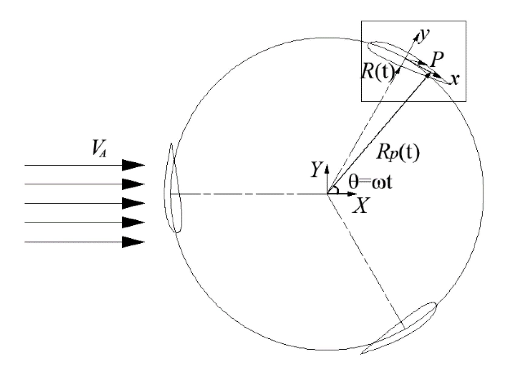
Figure 1. Reference coordinate system.
Energies 14 00049 g001
Figure 2. Local coordinate system.
Energies 14 00049 g002
Figure 3. The schematic diagram of the finite vortex method. Subscript i is the serial number of source and sink singularities, p is the number of blades, f represents the attached vortex on the blade, w represents the shedding vortex in the wake, superscript k is the time step.
Energies 14 00049 g003
Figure 4. The schematic diagram of how to allocate the vortex particles into the tree structure.
Energies 14 00049 g004
Figure 5. The schematic diagram of the redistribution of one vortex particle.
Energies 14 00049 g005
Figure 6. The correction coefficient along the streamwise direction. The X-axis is the downstream position normalized by the rotor diameter (X/D). The Y-axis represents two normalized parameters; one is the normalized velocity deficit ΔU/U0 (symbol ● and ■) of the wake model, the other is the correction coefficient (symbol × and ♦) obtained by the division.
Energies 14 00049 g006
Figure 7. The comparison of average velocity profiles at six different cross-sections. The X-axis represents the sum of the two normalized parameters; one is the streamwise position, which is normalized by the turbine diameter (X/D), the other is the velocity deficit, which is normalized by the inflow velocity (ΔU/U0). The Y-axis is the lateral position, which is normalized by the turbine diameter (Y/D). The data of black curves are from a published paper [10]; the color curves are calculated by the numerical method proposed in this paper.
Energies 14 00049 g007
Figure 8. The time-average velocity field of the VAWT wake. The X-axis is the streamwise position, which is normalized by the turbine diameter (X/D). The Y-axis is the lateral position, which is normalized by the turbine diameter (Y/D). The color bar is the velocity deficit, which is normalized by the inflow velocity (ΔU/U0). The blue dashed lines indicate that the velocity profiles at that location are used for comparison with the PIV experimental results.
Energies 14 00049 g008
Figure 9. The vorticity field at the near wake. The X-axis is the streamwise position which is normalized by the turbine diameter (X/D). The Y-axis is the lateral position which is normalized by the turbine diameter (Y/D). The color bar is the nondimensional vorticity which is normalized by the maximum vorticity in the field (ω/ωmax).
Energies 14 00049 g009
Figure 10. The eight moments of vorticity field in one period at a wide view. The interval of each moment is approximately equal to one rotation period. The X-axis is the streamwise position, which is normalized by the turbine diameter (X/D). The Y-axis is the lateral position, which is normalized by the turbine diameter (Y/D). The color bar is the nondimensional vorticity, which is normalized by the maximum vorticity in the field (ω/ωmax).
Energies 14 00049 g010aEnergies 14 00049 g010b
Table 1. Three steps of the wake simulation and the corresponding sub methods (Note: there is a label in bold before the method, which is the abbreviation of the method and will be used in the following analysis. The number of the label is the step of this process; the letter of the label is the initial of this method).
Main CategoryThe Description of Corresponding Submethods
The first step: How to calculate the blade load?1S—Streamtube method: The single streamtube model can be used to calculate the performance of the whole rotor, while the multiple streamtube models can be used to calculate the blade load at different azimuthal angles. The influence of upstream on downstream can be considered in the double multiple streamtube model [2].
1 V—Vortex Panel method: Based on the Kelvin theorem, the blade forces and vortex shedding at different azimuthal angles can be calculated. According to the types of singularity distribution and the way of the vortex shedding, this method can be further subdivided into many kinds [18,19,20,21,22,23]. The computational efficiency of the potential theory is high, but the results need to be modified at a high angle of attack [19,24].
1G—Grid-based method: There is the body-fitted grid method [25] and the immersed boundary method [26]. Relatively speaking, the computational accuracy is high, but the computational cost is also high.
1 T—The tabulated data of lift and drag coefficient: It is not necessary to calculate the blade force; only the aerodynamic angle of attack at different azimuthal angles need to be calculated. Then the lift and drag of the blade at the corresponding angle of attack can be obtained by looking up the database table. The lift and drag coefficients were measured at the static state [27] or the dynamic state [24] in wind tunnel experiments. Due to the dependence on the database, it may not be applicable for some new airfoils.
The second step: In which form does the blade force affect the flow field?2 F—The form of force source term: The force coefficient obtained by numerical calculation or database table can be regarded as the force source term, which should be smoothed by the kernel function and calculated by the grid-based method [28].
2 V—The form of vorticity source term: The circulation of the bound vortex can be transformed from the force coefficient according to the Kutta–Joukowski law, and the circulation of the shedding vortex can be calculated by the vortex panel method. Then, the circulation will be smoothed into vorticity source terms by the kernel function and calculated by the vortex method [27].
Note: This step does not need to be considered in the streamtube method.
The third step: How to simulate the VAT wake?3S—Streamtube method: The streamtube method is based on the momentum theory, and the velocity distribution of the VAT wake can be roughly estimated [2].
3VE—Vortex method with empirical viscosity: In order to produce the equivalent effect of viscous dissipation, an empirical decay function is added into the kernel function of the vorticity source term [27].
3VA—Vortex method with analytical viscosity: The vorticity source term could be discretized into the vortex particles, and the variation of vorticity caused by the viscous dissipation can be calculated analytically in the vorticity transport equation [29].
3G—Grid-based method: The evolution of the wake-field can be simulated by some grid-based methods (such as the finite difference method, the finite volume method [25], the Galerkin finite element method [30] and the lattice Boltzmann method [31]).
Note: The grid-based method (3G) is in the Eulerian framework, and the vortex method (3VE, 3VA) is a grid-free method in the Lagrangian framework.
Table 2. The basic information of the experiment.
Airfoil SectionNACA 0018Tip Speed Ratio1.1
Chord length3 cmWind speed at the mid-span9.43 m/s
Number of blades3Chord-based Reynolds number20,000
Rotor height15.5 cmInflow conditionTurbulent boundary layer
Rotor diameter16.6 cmExperimental conditionWind tunnel, stereo-PIV
Table 3. The parameters of these three vertical axis wind turbine (VAWT) wake models.
ModelNumber of BladesTip Speed RatioSolidityThe Downstream Transition LocationThe Power Function of Wake Velocity Deficit
Benchmark case (two-dimensional wake model)31.10.172Xt ≈ 4D Δ U U 0 = ( X X t ) 0.5
VAWT_1 [57] (three-dimensional wake model)31.20.32Xt ≈ 1.9D Δ U U 0 = 1.168 ( X X t ) 0.684 0.098
VAWT_2 [57] (three-dimensional wake model)21.220.21Xt ≈ 2.88D Δ U U 0 = 0.542 ( X X t ) 0.622 + 0.033
Publisher’s Note: MDPI stays neutral with regard to jurisdictional claims in published maps and institutional affiliations.