Alternative Ways of Cooling a Passive School Building in Order to Maintain Thermal Comfort in Summer


Abstract
:1. Introduction
2. Object and Methodology
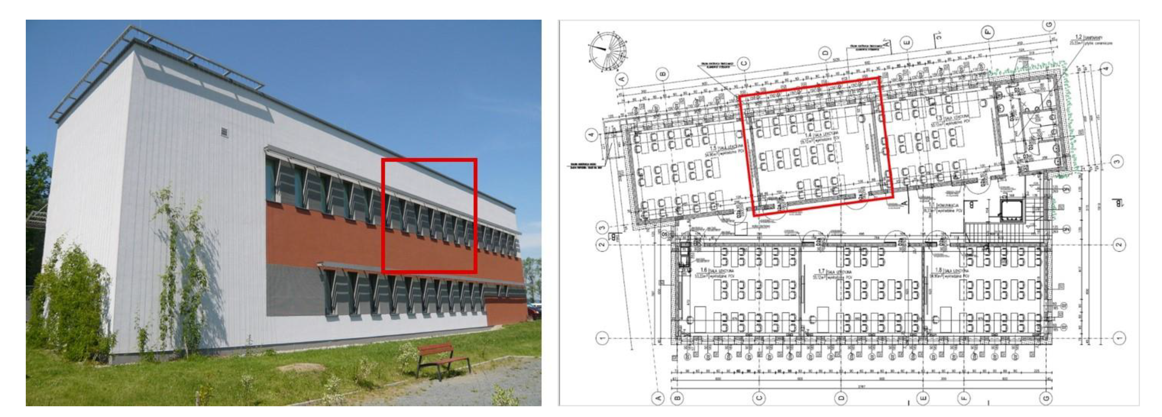
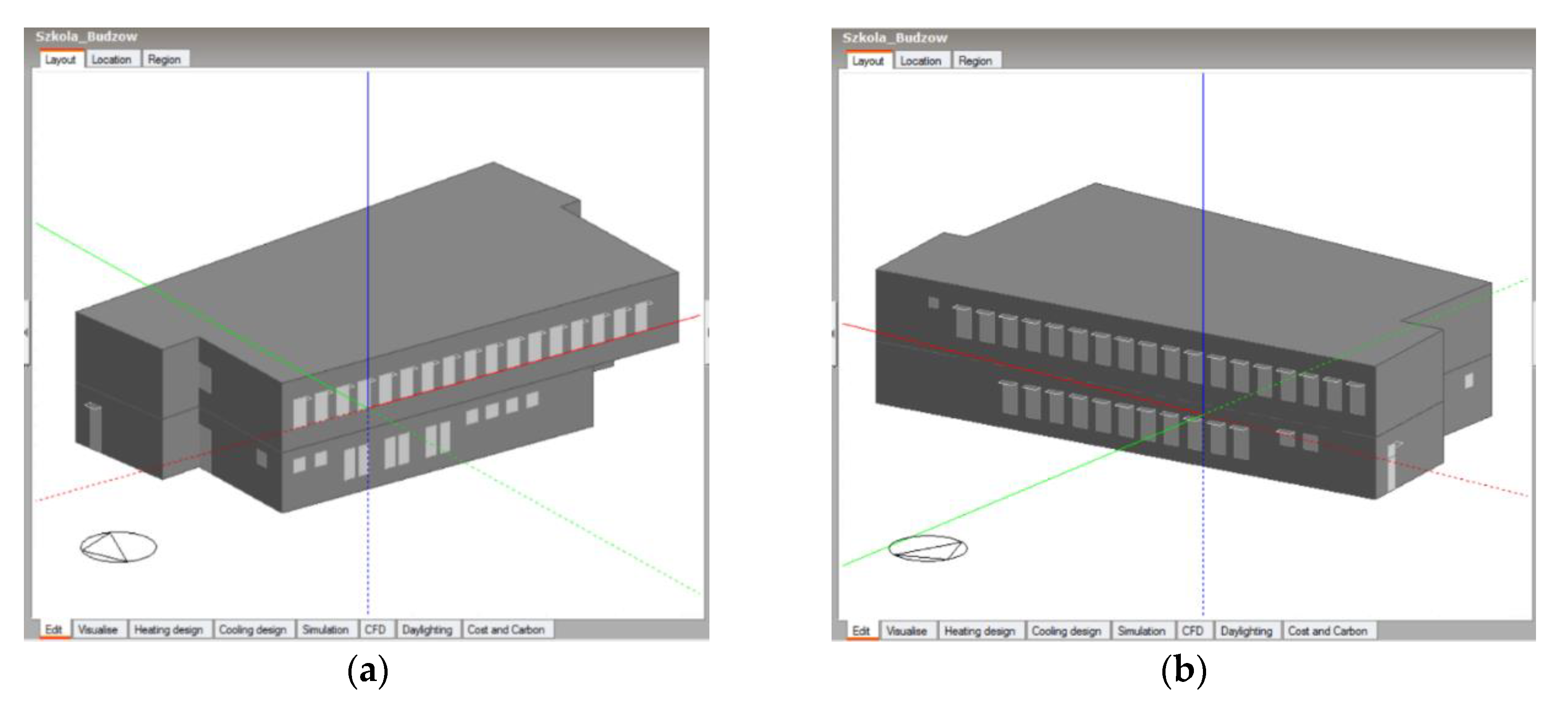
2.1. Passive School Building in Budzów
2.2. The Criterion for Ensuring Thermal Comfort
−0.42 × [(M − W) − 58.15] − 1.7 × 10⁻⁵ × M × (5867 − pa) − 0.0014 × M × (34 − ta)
−3.96 × 10⁻⁸ × fcl × [(tcl + 273)4 − (t-r + 273)4] − fcl × hc × (tcl − ta))
tcl = 35.7 − 0.028 × (M − W) − Icl{3.96 × 10⁻⁸ × fcl × [(tcl + 273)4 − (t-r + 273)4] + fcl × hc × (tcl − ta)}
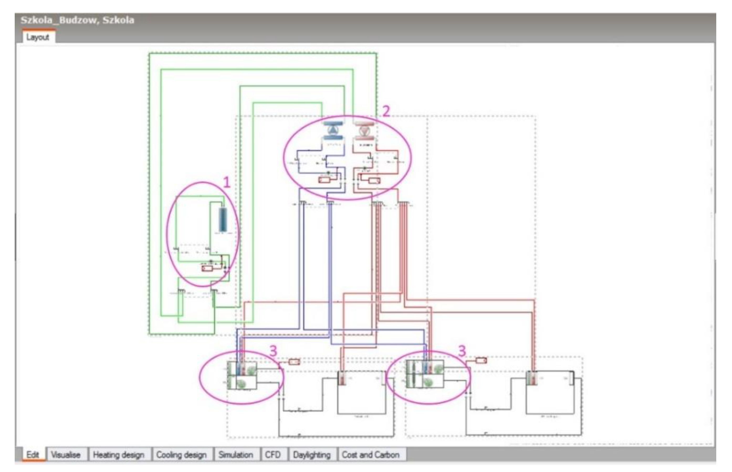
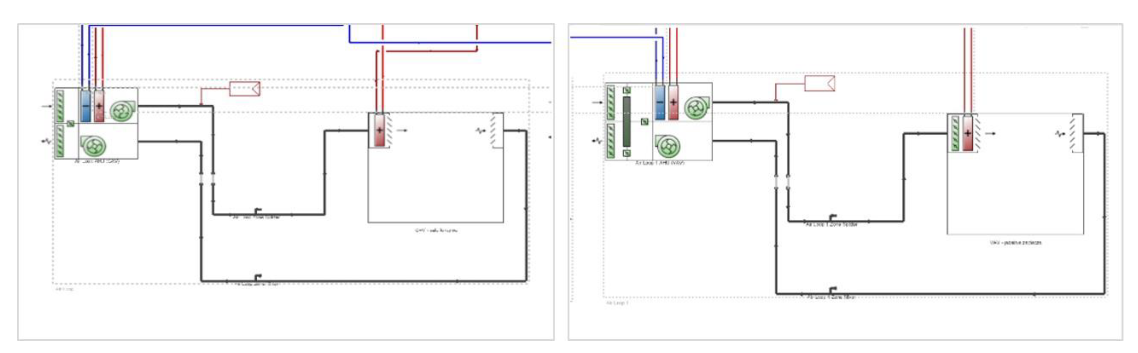
2.3. Simulation Model in Design Builder Program
3. Results of Thermal Comfort Analysis
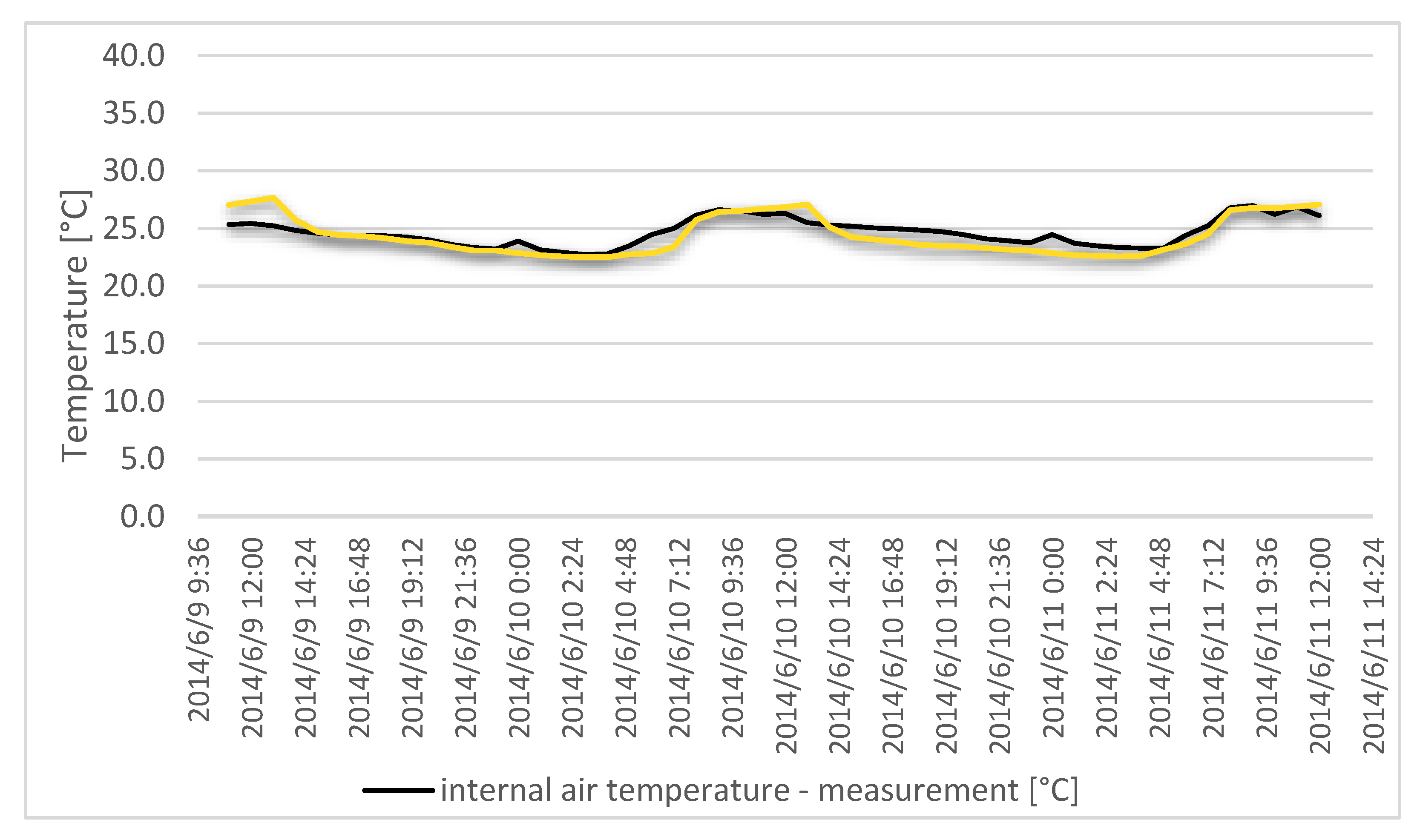
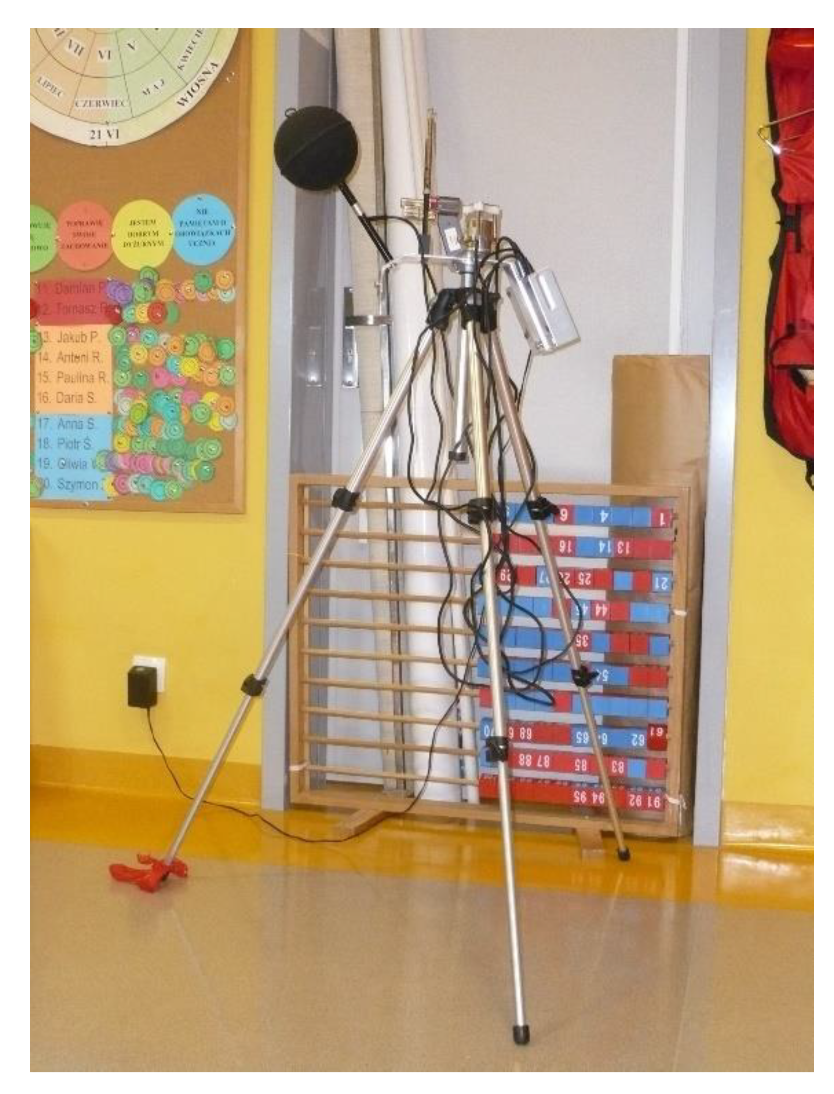
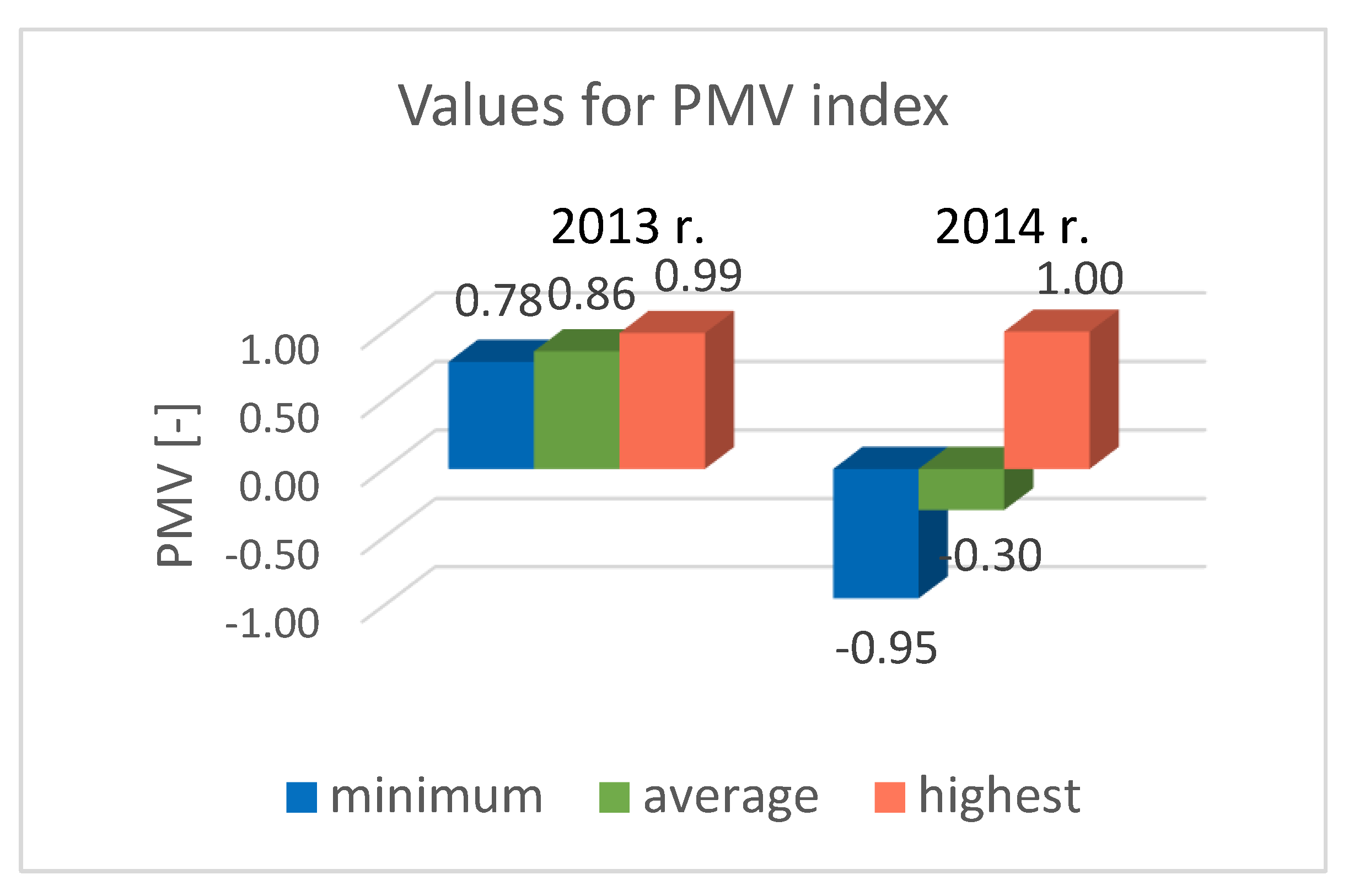
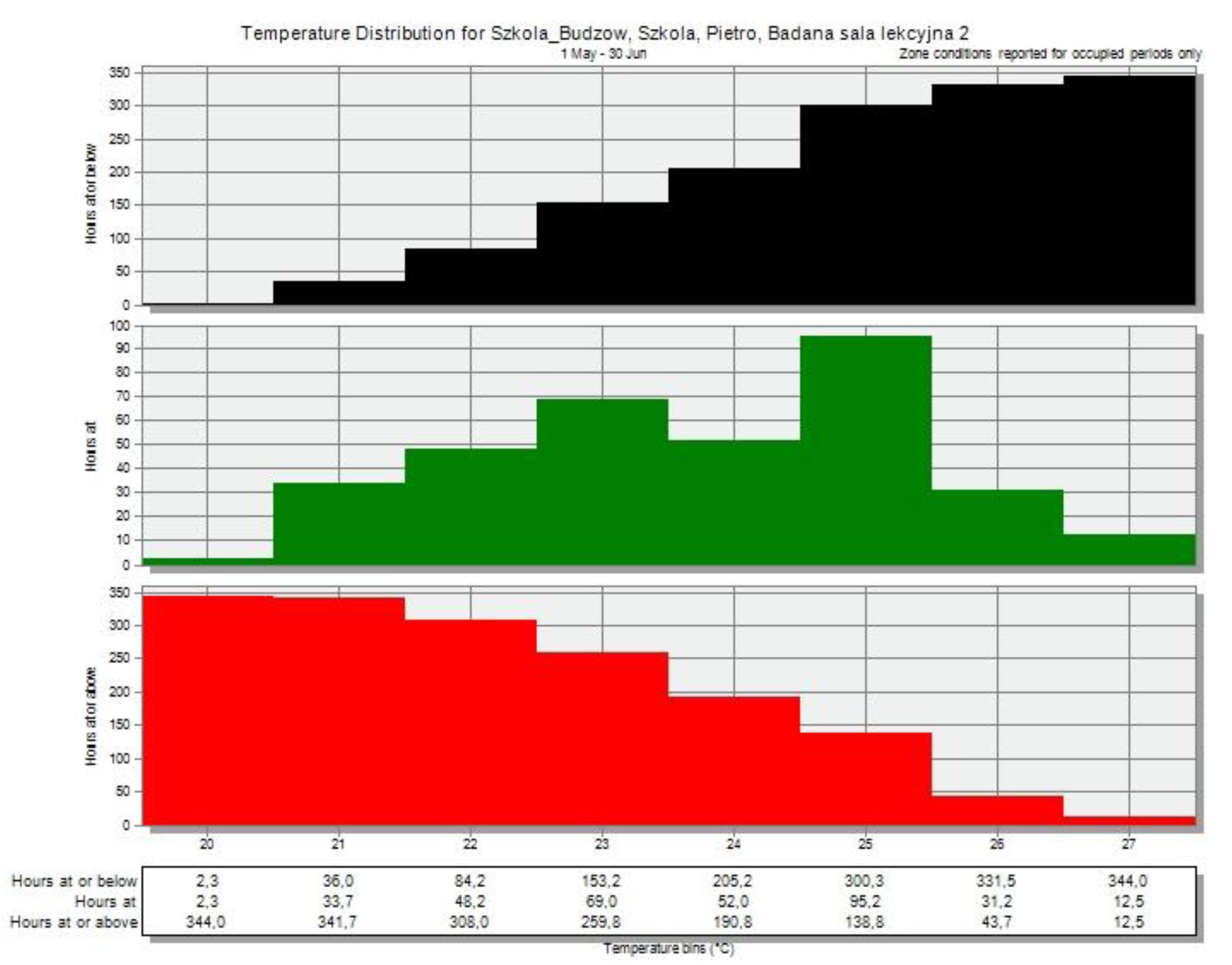
3.1. Experimental Analysis
3.2. Simulation Variants and Results
- ▪
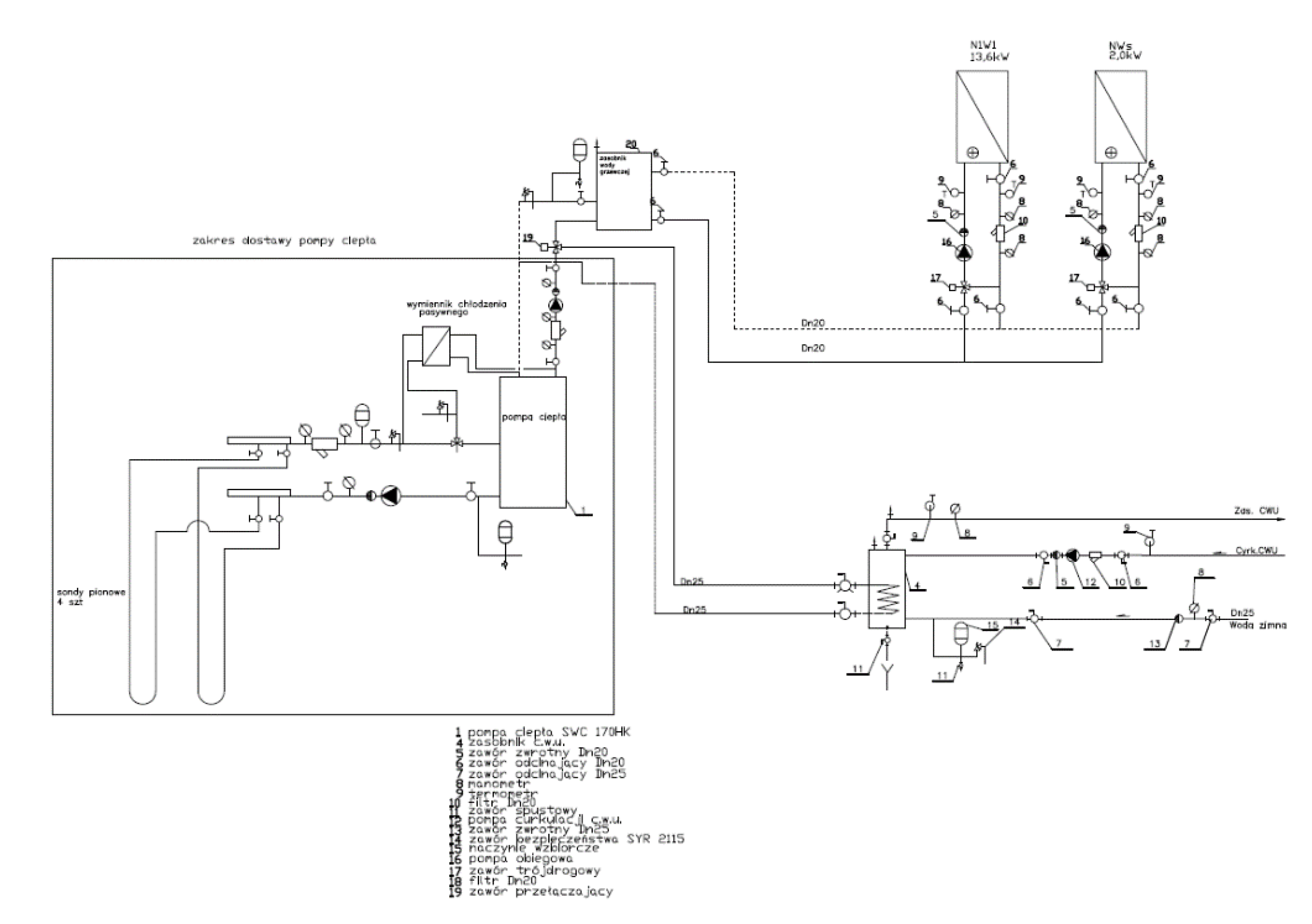
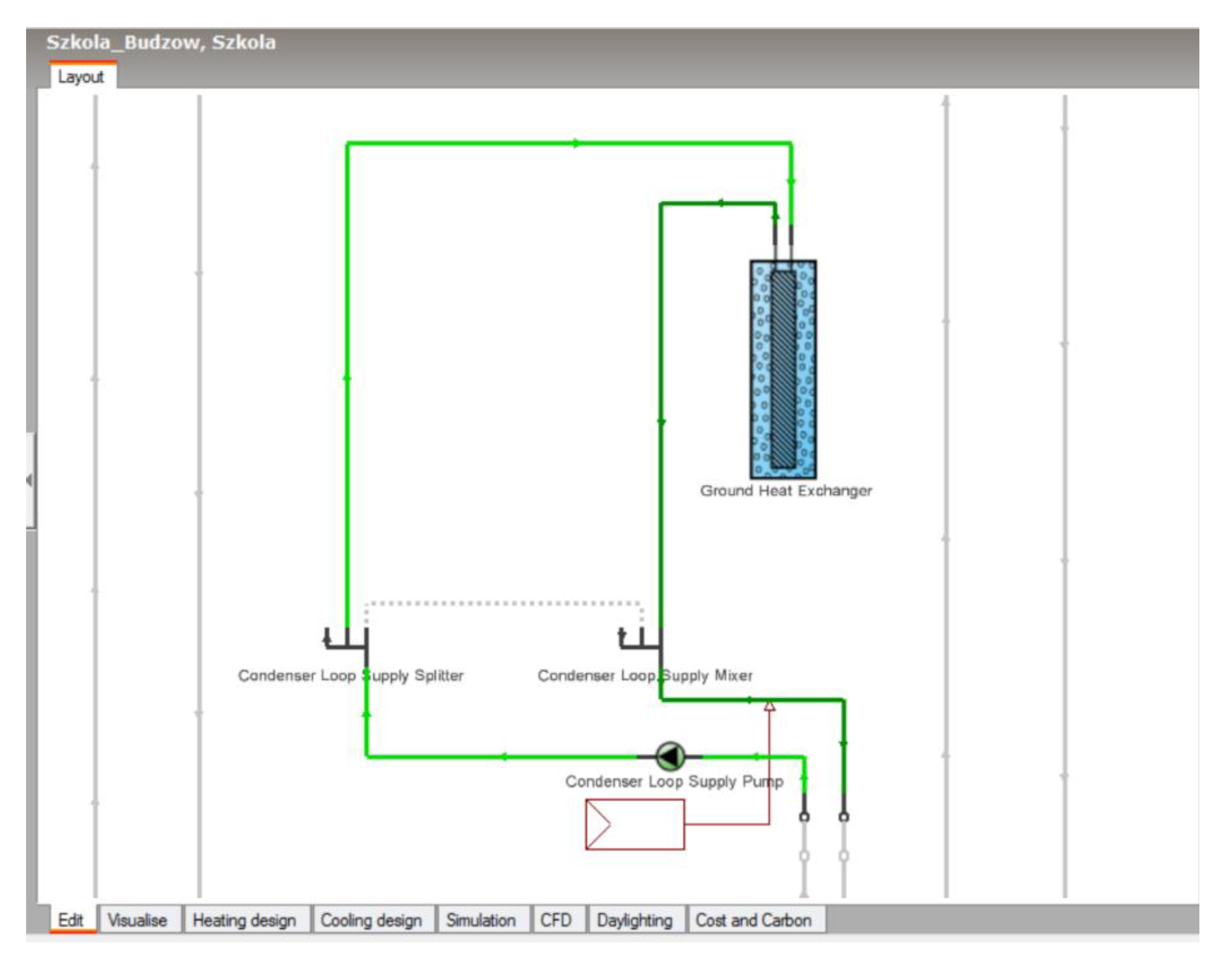
- Variant 1—Reference model. This building functions just as at the time of taking measurements; i.e., mechanical ventilation works with an efficiency of 100% (which in relation to the cubic capacity corresponds to approx. 4.5 h−1) when the facility is in use between 7.00 a.m.–3.00 p.m., and at night, from 11.00 p.m. to 6.00 a.m., the outdoor airflow is intensive (maximum ventilation capacity) to cool the building (free-cooling) when external conditions allow it, and at other times at least one air exchange per hour is carried out. This minimum outdoor airflow rate (1 h−1) applies when the outdoor air temperature is above 24 °C. Cooling is only passive—without the use of a heat pump, only the circulation pump is used; the water circulating in the ground exchanger is pumped to the heat recovery chiller, which cools the air distributed around the building;
- ▪
- Variant 2—Forced night ventilation (free-cooling). Maximum outdoor airflow (approx. 4.5 h−1) in the hours between 11.00 p.m. and 6.00 a.m. Mechanical ventilation kept on during the day from 7.00 a.m.–3.00 p.m.—at 4.5 h−1 regardless of external conditions, and at other times at 1 h−1. In this variant, no ground heat exchanger or natural ventilation were used;
- ▪
- Variant 3—Natural night cooling. Mechanical ventilation kept on during the day from 7.00 a.m. to 3.00 p.m.—approx. 4.5 h−1. At other times 1 h−1 was used, no ground exchanger was used, windows were kept closed during the day, natural night ventilation was used between 11.00 p.m. and 6.00 a.m. by way of a 20% tilt of all windows. The value of the minimum permissible indoor air temperature when tilting the windows is 20 °C;
- ▪
- Variant 4—Completely natural functioning of the building during the day and night. Mechanical ventilation turned off, no ground heat exchanger used, windows tilted during the day when the hall is in use, i.e., from 7.00 a.m. to 3 p.m. However, natural ventilation depends on external conditions (if Tout > Tint—windows are closed) and natural night ventilation between 11.00 p.m.–6.00 a.m. by the way of a 20% tilt of all windows. The value of the minimum permissible indoor air temperature when tilting the windows is 20 °C.
4. Aggregated Overheating Measure
- 1..
- The weighting factor kc equals 0 when PMV is within the recommended thermal comfort range: −0.5 < PMV < +0.5;
- 2.
- The weighting factor kc is taken in accordance with Table 6, depending on how much the maximum comfort range is exceeded by;
- 3.
- The products of the weighting factor kc and the number of hours for all ranges are summed up. For the sake of simplicity, it is assumed that the conventional unit of measurement is PMV-hour (PMVh).
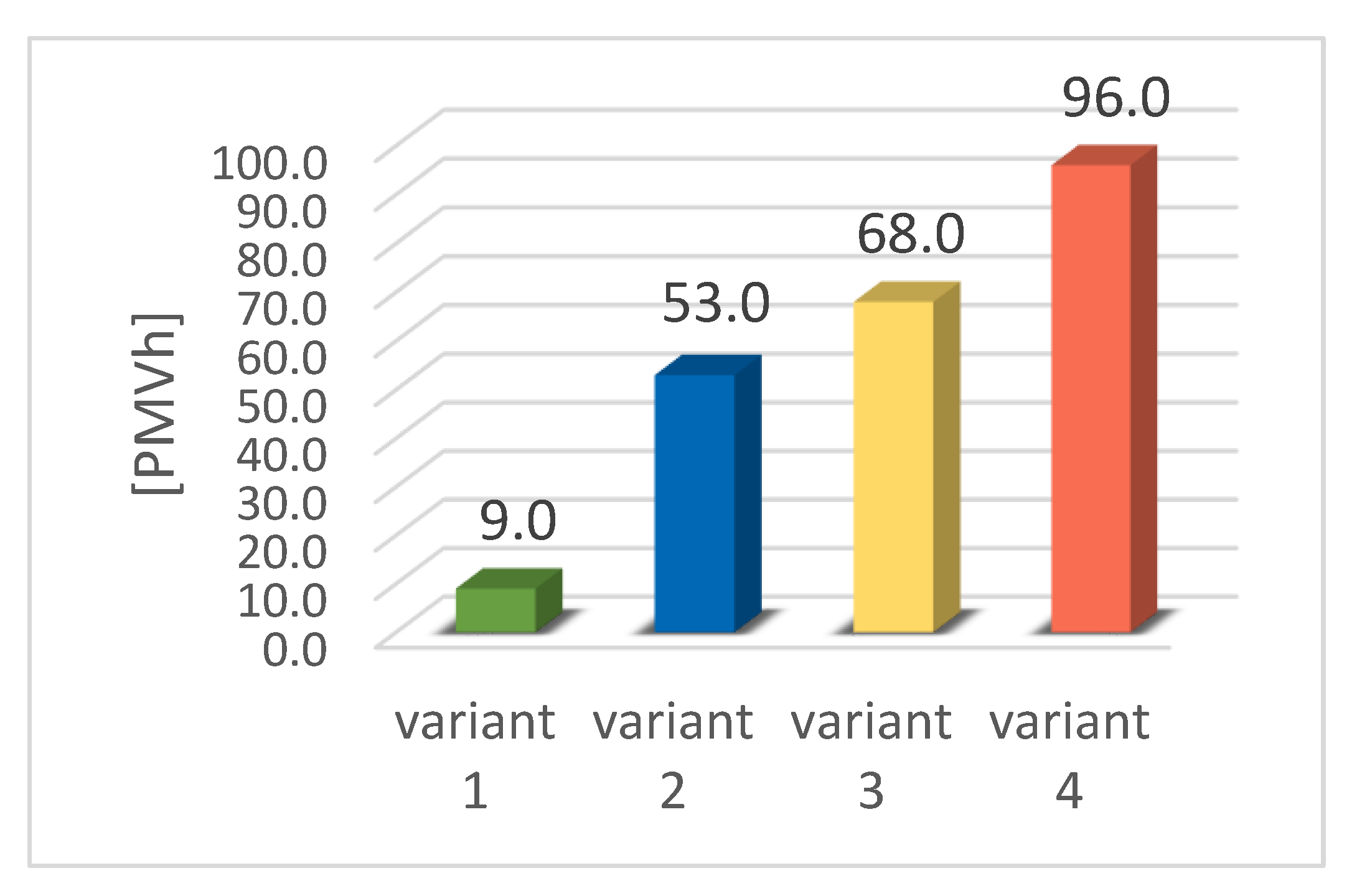
Variant 2: (15 · 1.0) + (15 · 2.0) + (2 · 4.0) = 53.0 PMVh
Variant 3: (16 · 1.0) + (18 · 2.0) + (4 · 4.0) = 68.0 PMVh
Variant 4: (22 · 1.0) + (15 · 2.0) + (11 · 4.0) = 96.0 PMVh
5. Discussion of Results
6. Conclusions
- ▪
- Intensive night mechanical ventilation combined with high thermal inertia of building structure, without a ground heat exchanger or heat pump, allows for a significant reduction of thermal discomfort in the interior analyzed. However, it is not possible to completely protect the building from overheating in this way in the hottest period of the year and to meet the requirements of the Fanger model at the same time;
- ▪
- However, in line with current trends as well as standard requirements, the assessment of the indoor climate in buildings without mechanical cooling takes into account the natural adaptation of the user’s body to the conditions of elevated ambient temperature. The conditions in the schoolroom analyzed fully met the adaptive comfort criteria included in the PN-EN 16798-1: 2019-06 standard;
- ▪
- The analyses carried out in this article confirmed the possibility of giving up the mechanical cooling system of the building using a hybrid system of mechanical and natural ventilation;
- ▪
- A ventilation system that is mechanically simple, however, requires an intelligent control system, which takes into account the prevailing hygienic requirements and at the same time minimizes heat gains from the outdoor air in the hot season, cool down the thermal mass of the building at night, but prevent its excessive cooling, etc.;
- ▪
- An adaptive method of determining thermal comfort should be used wherever possible. The synergy of the internal environment, controlled by users in response to the prevailing external conditions and low energy consumption in passive buildings, is an indispensable component of the idea of sustainable development. Taking into account the possibilities of human thermoregulation and active control of conditions by users through opening windows, using shading devices or controlled air exchange, it is possible to design buildings that guarantee good thermal conditions with minimal investment and operating costs and limited environmental impact.
Author Contributions
Funding
Data Availability Statement
Conflicts of Interest
References and Notes
- Dudzińska, A. Effectiveness of sunshades in shaping thermal comfort in a passive public building. J. Civ. Eng. Environ. Arch. 2015, XXXII, 39–48. [Google Scholar] [CrossRef]
- Jones, R.J.; Goodhew, S.; De Wilde, P. Measured Indoor Temperatures, Thermal Comfort and Overheating Risk: Post-occupancy Evaluation of Low Energy Houses in the UK. Energy Procedia 2016, 88, 714–720. [Google Scholar] [CrossRef] [Green Version]
- Pomfret, L.; Hashemi, A. Thermal Comfort in Zero Energy Buildings. Energy Procedia 2017, 134, 825–834. [Google Scholar] [CrossRef] [Green Version]
- Kisilewicz, T. Passive control of indoor climate conditions in low energy buildings. Energy Procedia 2015, 78, 49–54. [Google Scholar] [CrossRef] [Green Version]
- Bzowska, D. Risk of Overheating of Heat Insulated Buildings in the Summer Time. J. Civ. Eng. Environ. Arch. 2016, XXXIII, 43–52. [Google Scholar] [CrossRef] [Green Version]
- Bzowska, D. Changes in temperature in buildings in response to the changing climate. Tech. Trans. 2012, 3, 37–44. [Google Scholar]
- Fedorczak-Cisak, M.; Furtak, M.; Gintowt, J.; Kowalska-Koczwara, A.; Pachla, F.; Stypuła, K.; Tatara, T. Thermal and Vibration Comfort Analysis of a Nearly Zero-Energy Building in Poland. Sustainability 2018, 10, 3774. [Google Scholar] [CrossRef] [Green Version]
- Breesch, H.; Janssens, A. Reliable design of natural night ventilation using building simulation. In Proceedings of the 10th Thermal Performance of the Exterior Envelopes of Whole Buildings Conference: 30 Years of Reearch, Clearwater Beach, FL, USA, 2–7 December 2007; ASHARE: Atlanta, GA, USA, 2007. [Google Scholar]
- Kolokotroni, M.; Aronis, A. Cooling-energy reduction in air-conditioned offices by using night ventilation. Appl. Energy 1999, 63, 241–253. [Google Scholar] [CrossRef]
- Kolokotroni, M.; Webb, B.C.; Hayes, S.D. Summer cooling with night ventilation for office buildings in moderate climates. Energy Build. 1998, 27, 231–237. [Google Scholar] [CrossRef]
- Pfafferott, J.U.; Herkel, S.; Wambsganß, M. Design, monitoring and evaluation of a low energy office building with passive cooling by night ventilation. Energy Build. 2004, 36, 455–465. [Google Scholar] [CrossRef]
- Pfafferott, J.U.; Herkel, S.; Jäschke, M. Design of passive cooling by night ventilation: Evaluation of a parametric model and building simulation with measurements. Energy Build. 2003, 35, 1129–1143. [Google Scholar] [CrossRef]
- Firth, S.; Cook, M. Natural Ventilation in UK Schools: Design for Passive Cooling, Proceedings of Conference: Adapting to Change: New Thinking on Comfort: London, 2010, Network for Comfort and Energy Use in Buildings. Available online: http://nceub.org.uk (accessed on 24 December 2020).
- Tymkow, P.; Tassou, S.; Kolokotroni, M.; Jouhara, H. Building Services Design for Energy Efficient Buildings, Built Environment, Engineering & Technology; Routledge: London, UK, 2013. [Google Scholar] [CrossRef]
- Givoni, B. Effectiveness of mass and night ventilation in lowering the indoor daytime temperatures, Part I: 1993 experimental periods. Energy Build. 1998, 28, 25–32. [Google Scholar] [CrossRef]
- Kolokotroni, M. Night ventilation, cooling of office building: Parametric analyses of conceptual energy impacts. ASHRAE Trans. 2001, 107, 479–489. [Google Scholar]
- Gratia, E.; Bruyere, I.; De Herde, A. How to use natural ventilation to cool narrow office buildings. Energy Build. 2004, 39, 1157–1170. [Google Scholar] [CrossRef]
- Blondeau, P.; Spérandio, M.; Allard, F. Night ventilation for building cooling in summer. Sol. Energy 1997, 61, 327–335. [Google Scholar] [CrossRef]
- Breesch, H.; Bossaer, A.; Janssens, A. Passive cooling in a low-energy office building. Sol. Energy 2005, 79, 682–696. [Google Scholar] [CrossRef]
- Artmann, N.; Manz, H.; Heiselberg, P. Climatic potential for passive cooling of buildings by night-time ventilation in Europe. Appl. Energy 2007, 84, 187–201. [Google Scholar] [CrossRef]
- Artmann, N.; Manz, H.; Heiselberg, P. Parameter study on performance of building cooling by night-time ventilation. Renew. Energy 2008, 33, 2589–2598. [Google Scholar] [CrossRef]
- Kolokotroni, M. Night ventilation in commercial buildings. In Review of Low Energy Cooling Technologies, International Energy Agency, Energy Conservation in Buildings and Community Systems Programme, Annex 28 Low Energy Cooling, Subtask 1 Report; British Crown Copyright: London, UK, 1995; pp. 7–11. [Google Scholar]
- Lechner, N. Heating, Cooling, Lighting: Design Methods for Architects; John Wiley and Sons: New York, NY, USA, 2001; pp. 245–278. [Google Scholar]
- Santamouris, M.; Asimakopoulos, D. Passive Cooling of Buildings; James and James: London, UK, 1996. [Google Scholar]
- Geros, V.; Santamouris, M.; Papanikolaou, N.; Guarraccino, G. Night ventilation in urban environments. In Proceedings of the AIVC Conference, Bath, UK, 11–14 September 2001. [Google Scholar]
- Santamouris, M. Passive Cooling of Buildings, Advances of Solar Energy, ISES; James and James Science Publishers: London, UK, 2005. [Google Scholar]
- Detailed design of the communal elementary school in Budzów—Architecture, architect Bożena Bończa-Tomaszewska from the architectural studio Bończa-Studioarch.
- Polish Committee for Standardization. PN-EN 13829:2002, Thermal Performance of Buildings—Determination of Air Permeability of Buildings—Fan Pressurization Method; Polish Committee for Standardization: Warsaw, Poland, 2002. [Google Scholar]
- Dudzińska, A.; Kotowicz, A. Features of materials versus thermal comfort in a passive building. Procedia Eng. 2015, 108, 108–115. [Google Scholar] [CrossRef] [Green Version]
- Polish Committee for Standardization. PN-EN ISO 7730:2006, Ergonomics of the Thermal Environment—Analytical Determination and Interpretation of Thermal Comfort Using Calculation of the PMV and PPD Indices and Local Thermal Comfort Criteria; Polish Committee for Standardization: Warsaw, Poland, 2013. [Google Scholar]
- Polish Committee for Standardization. PN-EN ISO 7726: 2001, Ergonomics of the Thermal Environment-Instruments for Measuring Physical Quantities; Polish Committee for Standardization: Warsaw, Poland, 2013. [Google Scholar]
- Fanger, P.O. Thermal Comfort; Arkady: Warsaw, Poland, 1974. [Google Scholar]
- European Committee for Standardization. EN 16798-1:2019-06, Indoor Environmental Input Parameters for Design and Assessment of Energy Performance of Buildings Addressing Indoor Air Quality, Thermal Environment, Lighting and Acoustics; European Committee for Standardization: Brussels, Belgium, 2019. [Google Scholar]
- European Committee for Standardization. EN 12464-1:2011, Light and Lighting—Lighting of Work Places—Part 1: Indoor Work Places; European Committee for Standardization: Brussels, Belgium, 2011. [Google Scholar]
- Detailed design of the communal elementary school in Budzów Water and sewage installations central heating, hot water, mechanical ventilation and air conditioning, architect Bożena Bończa-Tomaszewska from the architectural studio Bończa-Studioarch.
- Jóźwiak, J.; Podgórski, J. Statistics from Scratch; PWE: Warszawa, Poland, 2009. [Google Scholar]
- Firląg, S. Co-Participation of Mechanical Ventilation with GHE in a Passive Building; Rynek Instalacyjny: Warsaw, Poland, 2007. [Google Scholar]
- Dudzińska, A. Ways of Shaping and Exploitation of Passive Public Utility Buildings Taking into Consideration the Requirements for Thermal Comfort. Ph.D. Thesis, Cracow University of Technology, Krakow, Poland, 2019. [Google Scholar]
- Figielek, A.; Królczyk, B. Passive Buildings; WIDP Wielkopolski Dom Pasywny: Poznań, Poland, 2015. [Google Scholar]
- NBS. Building Bulletin 87, Guidelines for Environmental Design in Schools, Department for Education and Skills, 2nd ed.; The Stationery Office Ltd: London, UK, 2003. [Google Scholar]
- Kaczmarczyk, J. Methods of Investigation and Evaluation of Thermal Environment Indoors; Politechnika Śląska: Gliwice, Poland, 2008. [Google Scholar]
- Pfafferott, J.U.; Herkel, S.; Kalz, D.E.; Zeuschner, A. Comparison of low-energy office buildings in summer using different thermal comfort criteria. Energy Build. 2007, 39, 750–757. [Google Scholar] [CrossRef]
- ASHRAE. ANSI/ASHRAE Standard 55-2013 Thermal Environmental Conditions for Human Occupancy; ASHRAE: Atlanta, GA, USA, 2017. [Google Scholar]
- Polish Committee for Standardization. PN-EN 16798-1:2019-06, Indoor Environmental Input Parameters for Design and Assessment of Energy Performance of Buildings Addressing Indoor Air Quality, Thermal Environment, Lighting and Acoustics; Polish Committee for Standardization: Warsaw, Poland, 2006. [Google Scholar]
- Polish Committee for Standardization. prCEN/TR 16798-2, Guideline for Using Indoor Environmental Input Parameters for the Design and Assessment of Energy Performance of Buildings; Polish Committee for Standardization: Warsaw, Poland, 2019. [Google Scholar]


| Environmental Parameter | Number of Hours in Specific Ranges of Outdoor Temperatures (out of 1464 h) | ||||
|---|---|---|---|---|---|
| <15 °C | 15–20 °C | 20–25 °C | 25–30 °C | >30 °C | |
| Outdoor air temperature | 723 | 440 | 211 | 75 | 15 |
| Variants/Characteristics | Variant 1 Reference Model | Variant 2 | Variant 3 | Variant 4 |
|---|---|---|---|---|
| Time when the object is in use | 7.00 a.m.–3.00 p.m. | 7.00 a.m.–3.00 p.m. | 7.00 a.m.–3.00 p.m. | 7.00 a.m.–3.00 p.m. |
| Mechanical ventilation [h−1] | ||||
| 7.00 a.m.–3.00 p.m. | 4.5 | 4.5 | 4.5 | no |
| 11.00 p.m.–6.00 a.m. | free-cooling | free-cooling | no | no |
| 3.00–11.00 p.m. | 1.0 | 1.0 | 1.0 | no |
| Use of a ground heat exchanger | yes | no | no | no |
| Natural ventilation | N | |||
| 7.00 a.m.–3.00 p.m. | no | no | no | Yes if Tout > Tint—windows are closed |
| night | no | no | 20% | 20% |
| Simulation Variants | Indoor Air Temperature ta [°C] | Operative Temperature to [°C] | Radiation Temperature tr [°C] |
|---|---|---|---|
| Highest Value | Highest Value | Highest Value | |
| Variant 1 | 27.7 | 27.6 | 27.5 |
| Variant 2 | 31.2 | 30.3 | 29.3 |
| Variant 3 | 31.6 | 30.8 | 30.0 |
| Variant 4 | 31.5 | 30.7 | 29.9 |
| Simulation Variants | Number of Hours in a Given Temperature Range (out of 344 h) | Degree-Hours of Discomfort | |
|---|---|---|---|
| 24.0–27.0 °C | >27.0 °C | ||
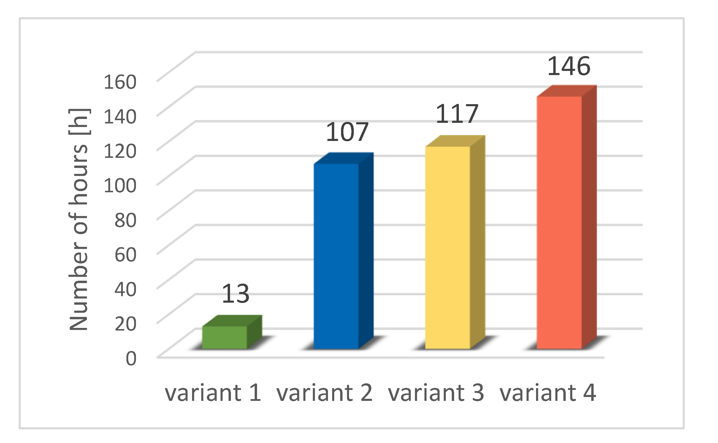
| Variant 1 | 177 | 13 | 13 |
| Variant 2 | 113 | 44 | 107 |
| Variant 3 | 114 | 47 | 117 |
| Variant 4 | 116 | 65 | 146 |
| Simulation Variants | Number of Hours in the Thermal Comfort Range−0.5 < PMV < +0.5 | Number of Hours in the Range +0.5 < PMV < +1.0 | Number of Hours in the Range +1.0 < PMV < +1.5 | Number of Hours in the Range +1.5 < PMV < +2.0 | Weighted Measure of Discomfort Related to Overheating [PMVh] |
|---|---|---|---|---|---|
| variant 1 | 165 | 9 | 0 | 0 | 9.0 |
| variant 2 | 110 | 15 | 15 | 2 | 53.0 |
| variant 3 | 112 | 16 | 18 | 4 | 68.0 |
| variant 4 | 136 | 22 | 15 | 11 | 96.0 |
| PMV | Weighting Factor kc |
|---|---|
| −0.5 < PMV < +0.5 | 0 |
| +0.5 < PMV < +1.0 | 1 |
| +1.0 < PMV < +1.5 | 2 |
| +1.5 < PMV < +2.0 | 4 |
Publisher’s Note: MDPI stays neutral with regard to jurisdictional claims in published maps and institutional affiliations. |
© 2020 by the authors. Licensee MDPI, Basel, Switzerland. This article is an open access article distributed under the terms and conditions of the Creative Commons Attribution (CC BY) license (http://creativecommons.org/licenses/by/4.0/).
Share and Cite
Dudzińska, A.; Kisilewicz, T. Alternative Ways of Cooling a Passive School Building in Order to Maintain Thermal Comfort in Summer. Energies 2021, 14, 70. https://doi.org/10.3390/en14010070
Dudzińska A, Kisilewicz T. Alternative Ways of Cooling a Passive School Building in Order to Maintain Thermal Comfort in Summer. Energies. 2021; 14(1):70. https://doi.org/10.3390/en14010070
Chicago/Turabian StyleDudzińska, Anna, and Tomasz Kisilewicz. 2021. "Alternative Ways of Cooling a Passive School Building in Order to Maintain Thermal Comfort in Summer" Energies 14, no. 1: 70. https://doi.org/10.3390/en14010070