
Optimal Voltage–Frequency Regulation in Distributed Sustainable Energy-Based Hybrid Microgrids with Integrated Resource Planning

 ,
,  , and
, and
Abstract
:1. Introduction
- (a)
- Proposing IRP for simultaneous voltage–frequency regulation of multi-unit-based distributed microgrids by designing combined storage-based VIS system for SSM and HEV charging station-based DRS for DSM.
- (b)
- Designing a novel QCSHO algorithm by hybridizing CLS and QOBL with basic SHO algorithms to tune the PID controller gains, introducing integral-square of weighted absolute error (ISWAE) for interconnected microgrids.
- (c)
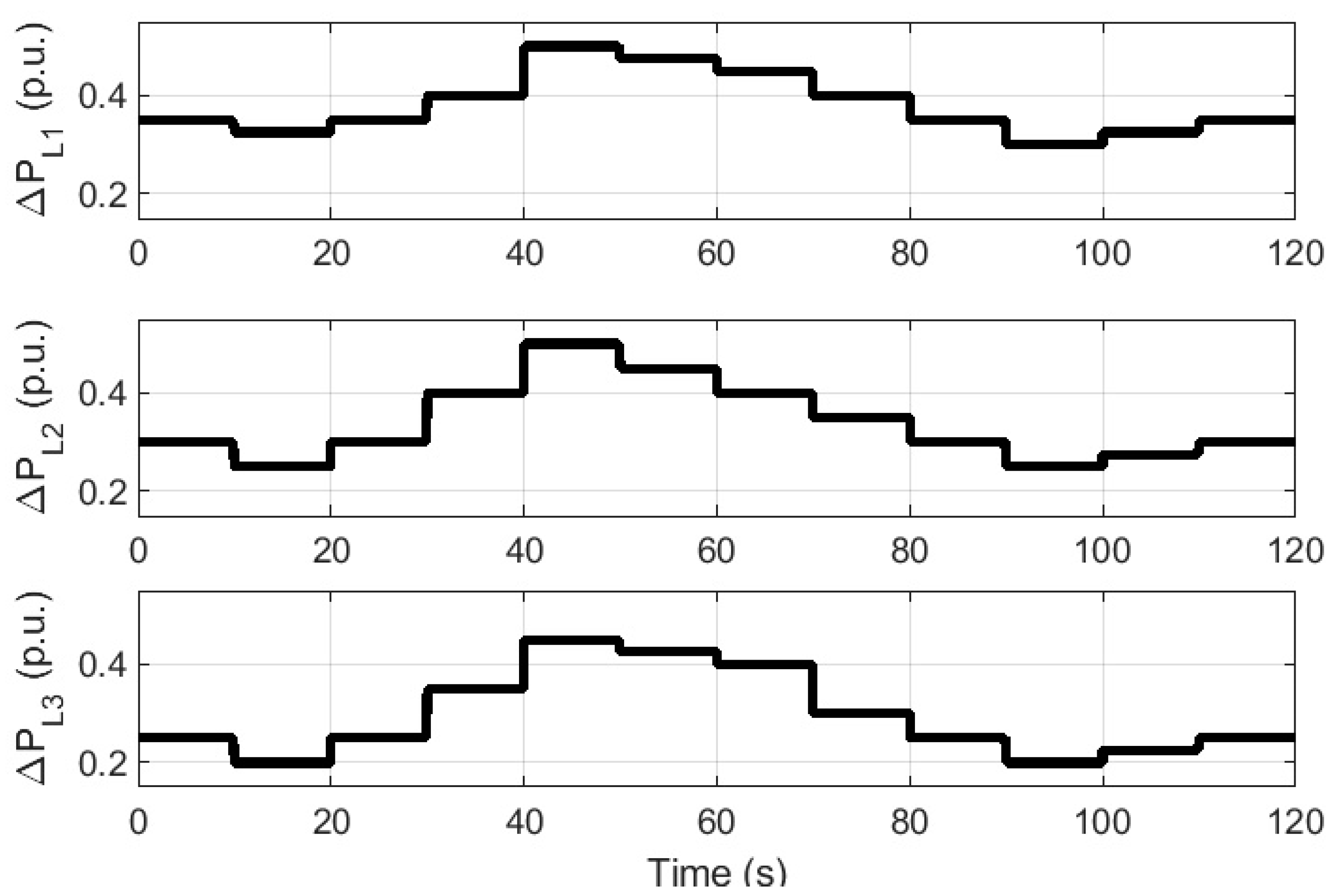
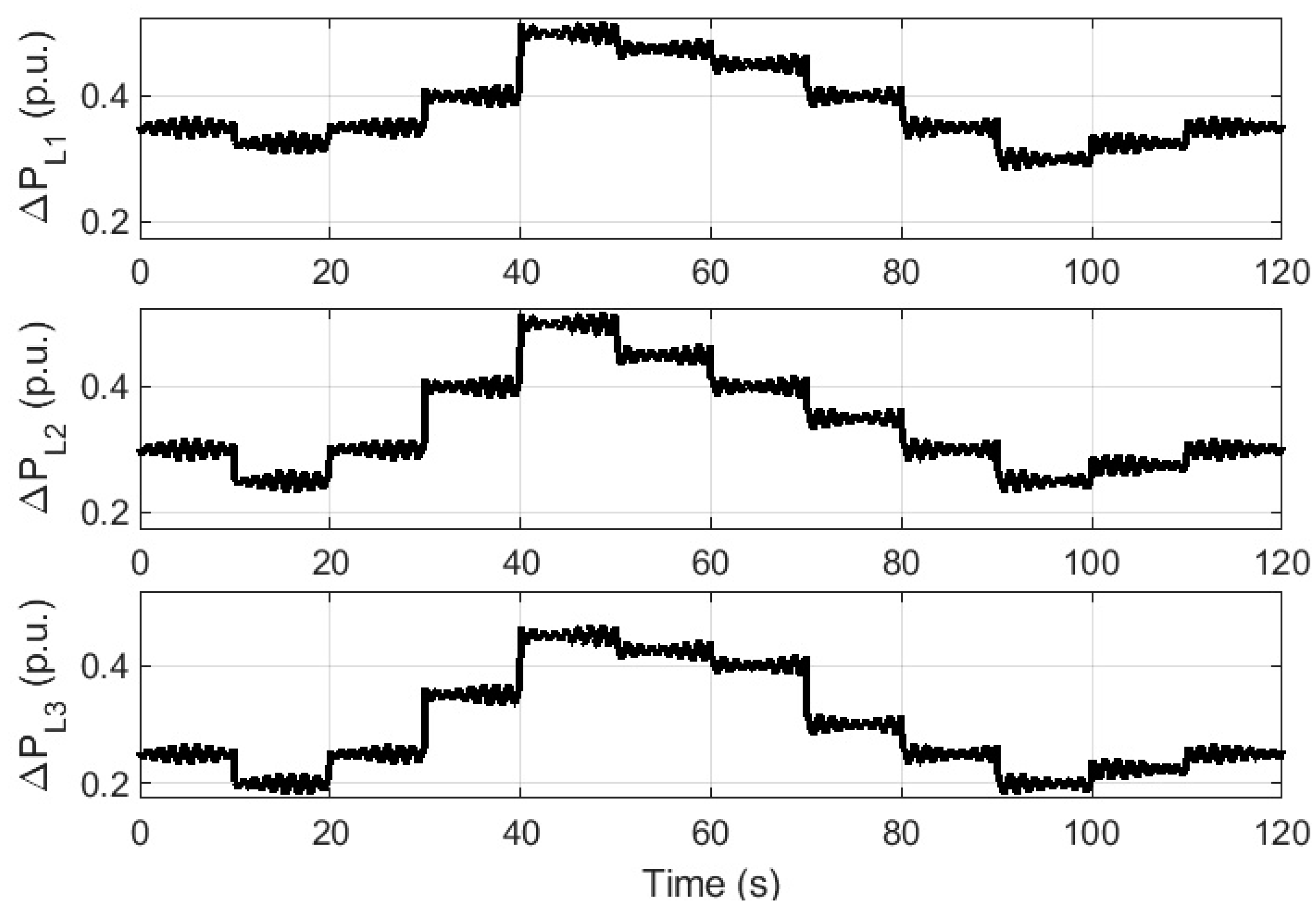
- Analyzing the system responses with the proposed VIS/DRS units considering random linear/non-linear loadings for exact replication of real-time load patterns including recorded wind/solar data to check the reliability of the distributed microgrids round the year.
- (d)
- Investigating the optimal allocation of VIS/DRS units for economic operation of distributed microgrids.
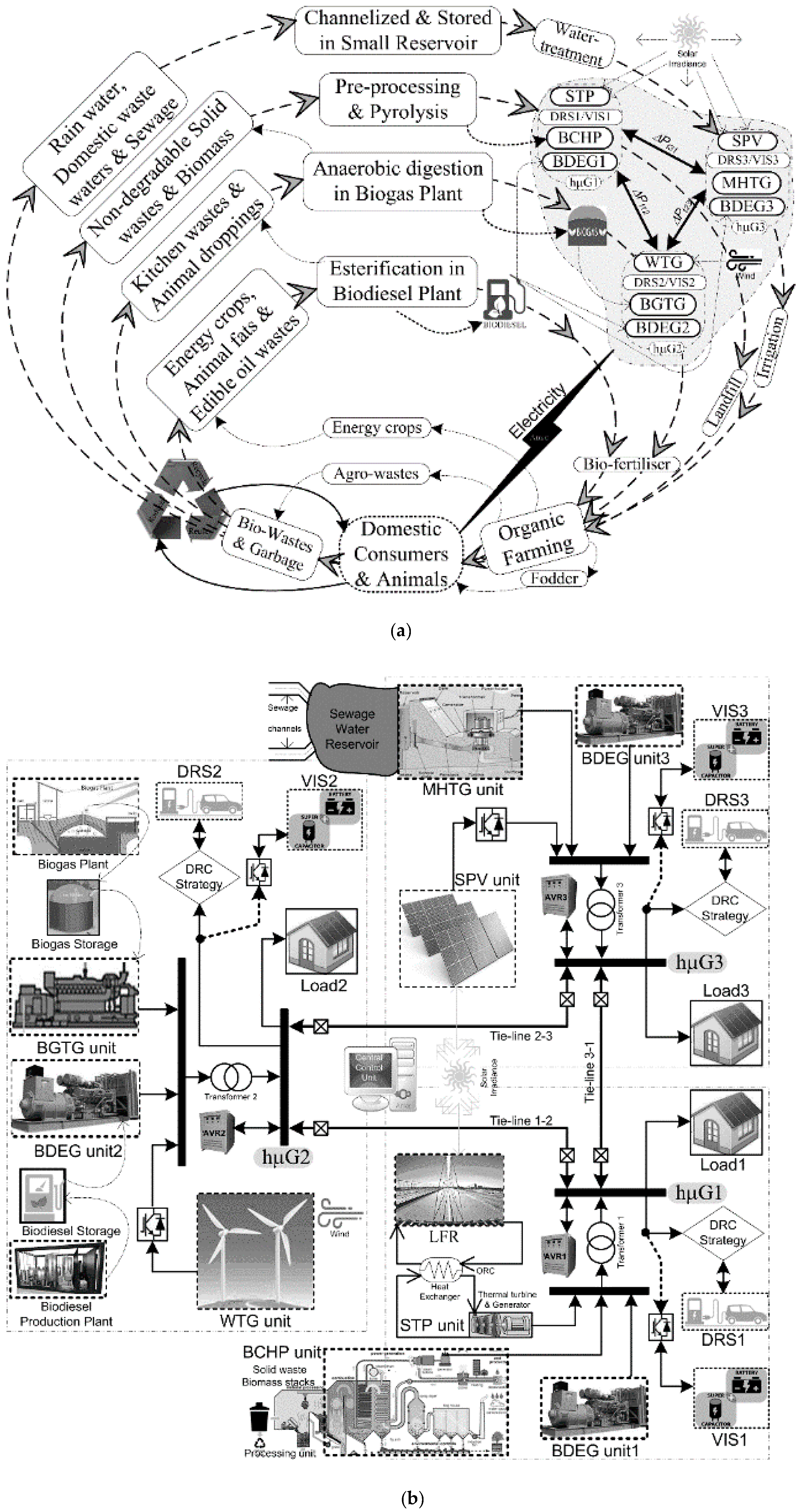
2. Modeling of Distributed Microgrid System
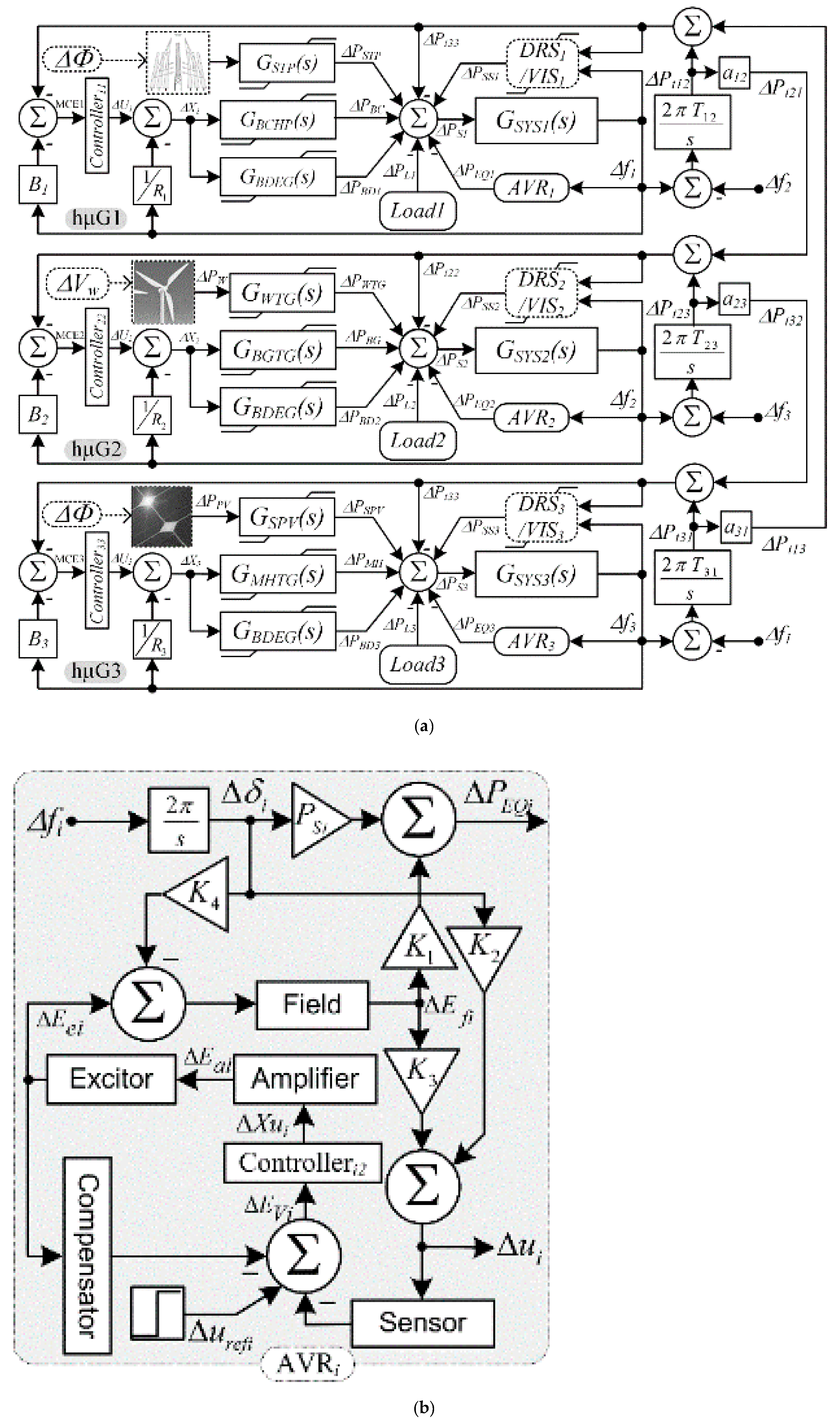
2.1. Frequency Regulation System
2.2. Voltage Regulation System
2.3. Virtual Inertia Support System
2.4. Demand Response Support System
2.5. Renewable Energy System
2.6. Bioenergy Generator System
2.7. Load-Generator Dynamic System
2.8. Objective Function Formulation
3. Quasi Oppositional Chaotic Selfish Herd Optimization
4. Simulation Studies and Analysis of Results
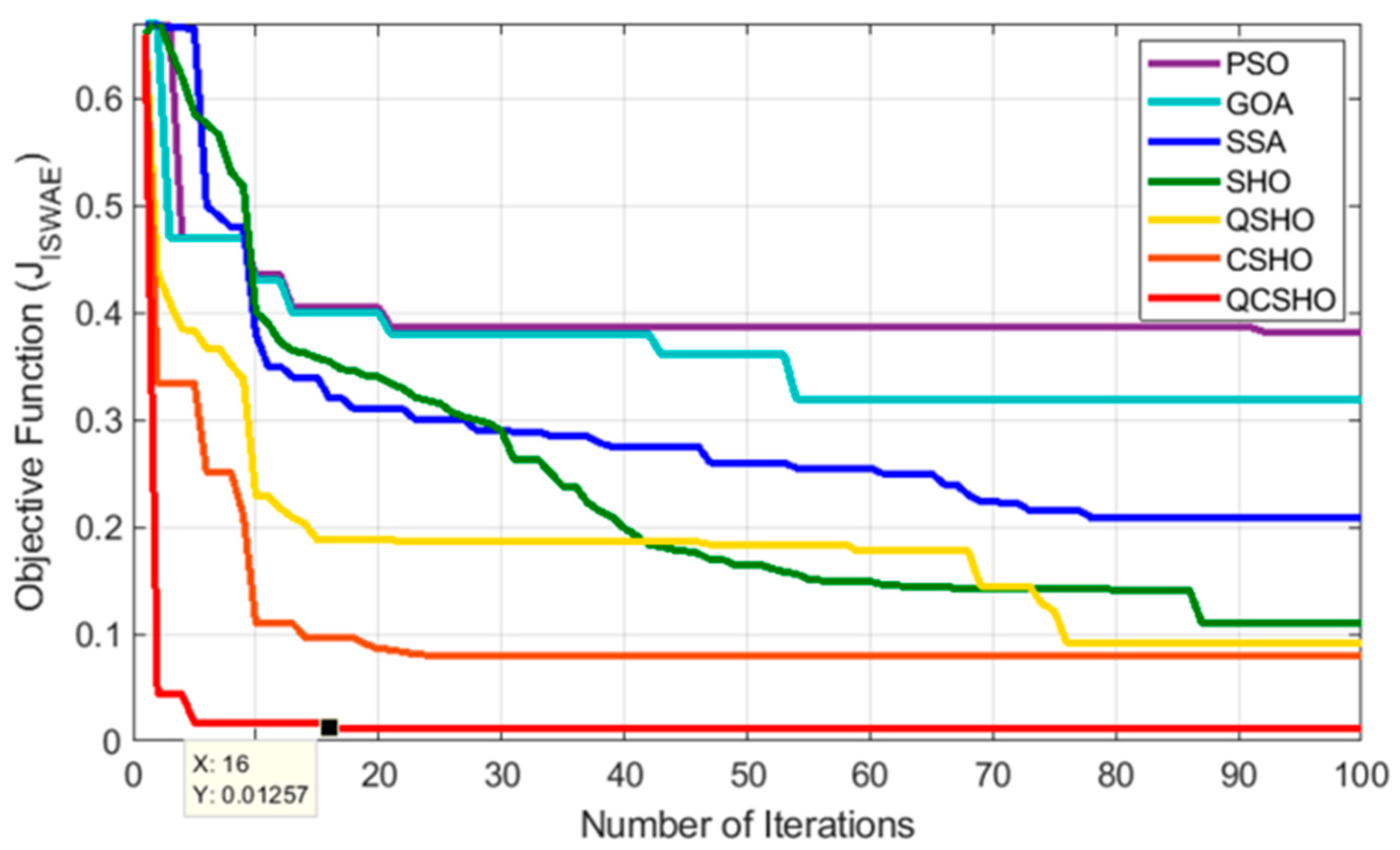
4.1. Step Response Analysis for Method Selection
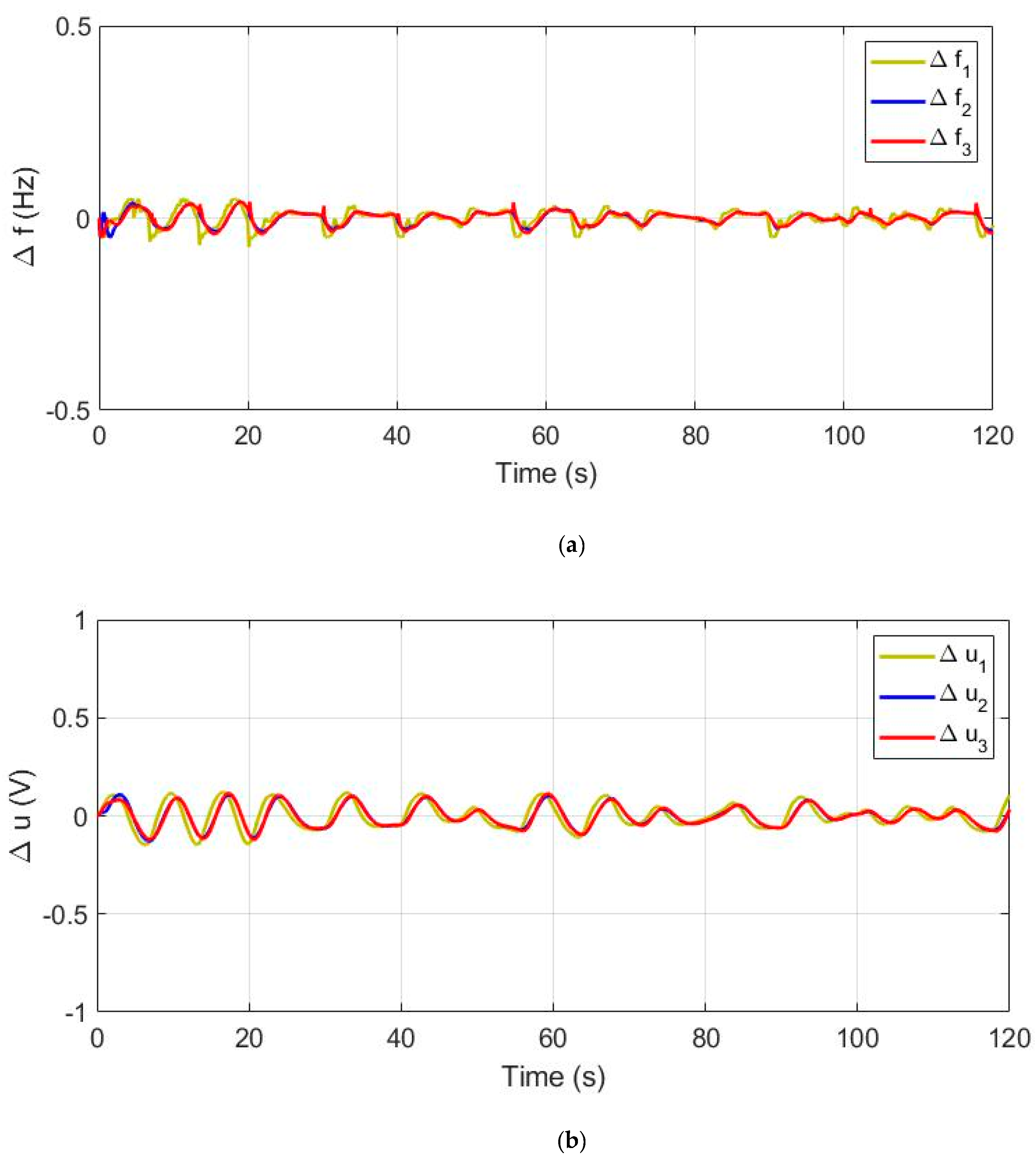
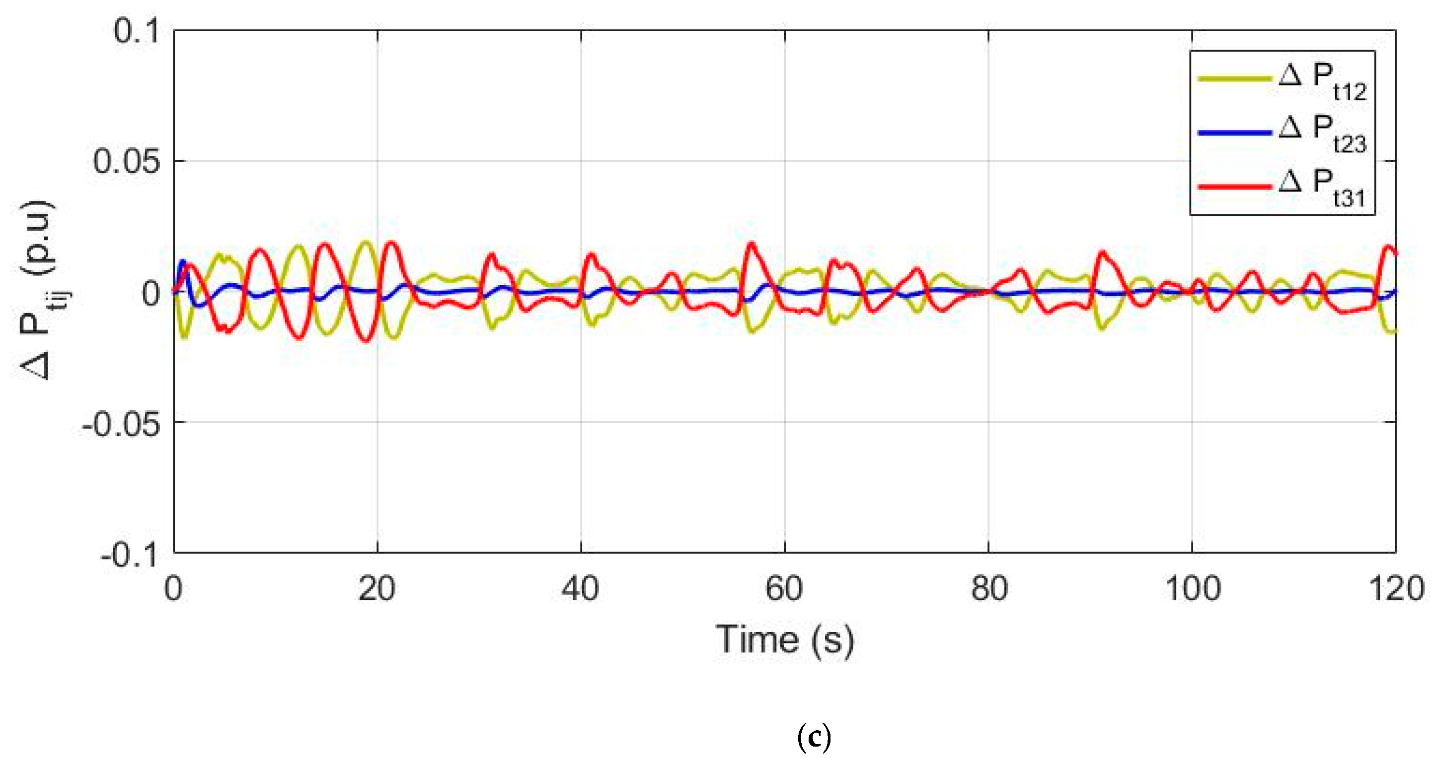
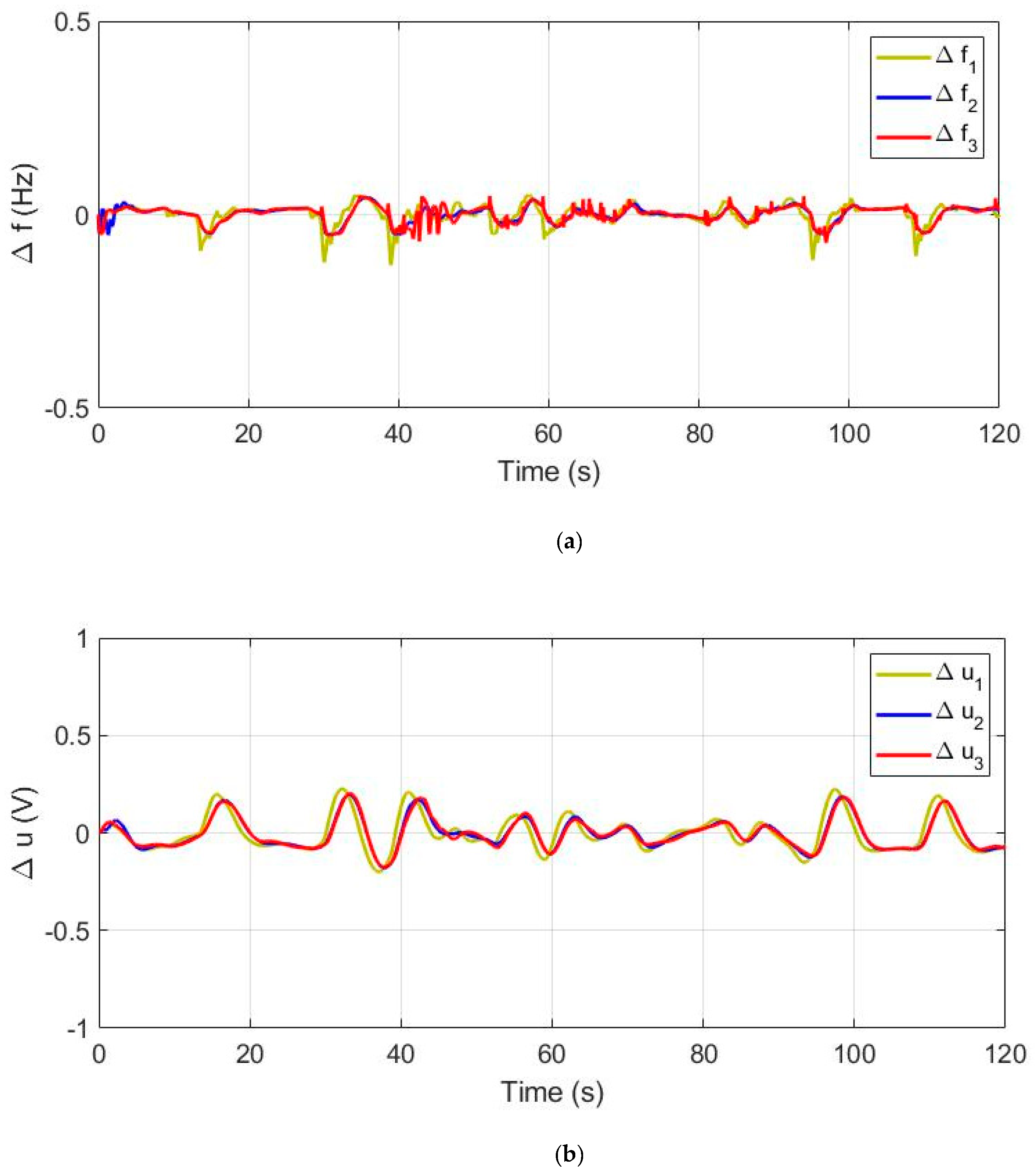
4.2. Response of Distributed Microgrids
4.3. Optimal Allocation of VIS/DRS Units
5. Conclusions
Author Contributions
Funding
Institutional Review Board Statement
Informed Consent Statement
Data Availability Statement
Conflicts of Interest
References
- Barik, A.K.; Das, D.C. Coordinated regulation of Voltage and Load-Frequency in Demand response supported Bio-renewable cogeneration based Isolated hybrid Microgrid with Quasi-oppositional Selfish Herd Optimisation. Int. Trans. Electr. Energy Syst. 2020, 30, 1–22. [Google Scholar] [CrossRef]
- Zou, H.; Mao, S.; Wang, Y.; Zhang, F.; Chen, X.; Cheng, L. A survey of energy management in interconnected multi-microgrids. IEEE Access 2019, 7, 72158–72169. [Google Scholar] [CrossRef]
- Bevrani, H.; Ise, T.; Miura, Y.; Watanabe, M. Virtual synchronous generators: A survey and new perspectives. Int. J. Electr. Power Energy Syst. 2014, 54, 244–254. [Google Scholar] [CrossRef]
- Yang, L.; Hu, Z.; Xie, S.; Kong, S.; Lin, W. Adjustable virtual inertia control of supercapacitors in PV-based AC microgrid cluster. Electr. Power Syst. Res. 2019, 73, 71–85. [Google Scholar] [CrossRef]
- Kerdphol, T.; Rahman, F.S. Robust virtual inertia control of a low inertia microgrid considering frequency measurement effects. IEEE Access 2019, 7, 57550–57560. [Google Scholar] [CrossRef]
- Fini, M.H.; Golshan, M.E.H. Determining optimal virtual inertia and frequency control parameters to preserve the frequency stability in islanded microgrids with high penetration of renewables. Electr. Power Syst. Res. 2018, 154, 13–22. [Google Scholar] [CrossRef]
- Kerdphol, T.; Watanabe, M.; Mitani, Y.; Phunpeng, V. Applying Virtual Inertia Control Topology to SMES System for Frequency Stability Improvement of Low-Inertia Microgrids Driven by High Renewables. Energies 2019, 12, 3902. [Google Scholar] [CrossRef] [Green Version]
- Shintai, T.; Miura, Y.; Ise, T. Oscillation damping of a distributed generator using a virtual synchronous generator. IEEE Trans. Power Deliv. 2014, 29, 668–676. [Google Scholar] [CrossRef]
- Fathi, A.; Shafiee, Q.; Bevrani, H. Robust frequency control of microgrids using an extended virtual synchronous generator. IEEE Trans. Power Syst. 2018, 33, 6289–6297. [Google Scholar] [CrossRef]
- Phurailatpam, C.; Rather, Z.H.; Bahrani, B.; Doolla, S. Measurement Based Estimation of Inertia in AC Microgrids. IEEE Trans. Sustain. Energy 2020, 11, 1975–1985. [Google Scholar] [CrossRef]
- Barik, A.K.; Jaiswal, S.; Das, D.C. Recent trends and development in hybrid microgrid: A review on energy resource planning and control. Int. J. Sustain. Energy 2021, 1–15. [Google Scholar] [CrossRef]
- Bao, Y.Q.; Li, Y.; Wang, B.; Hong, Y.-Y. Design of a hybrid hierarchical demand response control scheme for the frequency control. IET Gener. Transm. Distrib. 2015, 9, 2303–2310. [Google Scholar] [CrossRef]
- Bao, Y.Q.; Li, Y.; Wang, B.; Hu, M.; Chen, P. Demand response for frequency control of multi-area power system. J. Mod. Power Syst. Clean Energy 2017, 5, 20–29. [Google Scholar] [CrossRef] [Green Version]
- Zakariazadeh, A.; Homaee, O.; Jadid, S.; Siano, P. A new approach for real time voltage control using demand response in an automated distribution system. Appl. Energy 2014, 117, 157–166. [Google Scholar] [CrossRef]
- Pourmousavi, S.A.; Nehrir, M.H. Real-time central demand response for primary frequency regulation in microgrids. IEEE Trans. Smart Grid 2012, 3, 1988–1996. [Google Scholar] [CrossRef]
- Ly, A.; Bashash, S. Fast Transactive Control for Frequency Regulation in Smart Grids with Demand Response and Energy Storage. Energies 2020, 13, 4771. [Google Scholar] [CrossRef]
- Barik, A.K.; Das, D.C. Proficient Load-frequency regulation of demand response supported Bio-renewable cogeneration based hybrid Microgrids with Quasi-oppositional Selfish-herd Optimisation. IET Gener. Transm. Distrib. 2019, 13, 2889–2898. [Google Scholar] [CrossRef]
- Barik, A.K.; Das, D.C.; Muduli, R. Demand Response Supported Optimal Load-Frequency Regulation of Sustainable Energy based Four-Interconnected Unequal Hybrid Microgrids. In Proceedings of the IEEE International Conference on Sustainable Energy Technologies and Systems (ICSETS), Bhubaneswar, India, 26 February–1 March 2019. [Google Scholar]
- Othman, A.M.; El-Fergany, A.A. Design of robust model predictive controllers for frequency and voltage loops of interconnected power systems including wind farm and energy storage system. IET Gener. Transm. Distrib. 2018, 12, 4276–4283. [Google Scholar] [CrossRef]
- Barik, A.K.; Das, D.C. Expeditious frequency control of solar photovoltaic/biogas/biodiesel generator based isolated renewable microgrid using grasshopper optimisation algorithm. IET Renew. Power Gener. 2018, 12, 1659–1667. [Google Scholar] [CrossRef]
- Bhuyan, M.; Barik, A.K.; Das, D.C. GOA optimized frequency control of Solar Thermal/Sea-Wave/Biodiesel Generator based interconnected hybrid microgrids with DC link. Int. J. Sustain. Energy 2020, 39, 615–633. [Google Scholar] [CrossRef]
- Barik, A.K.; Tripathy, D.; Das, D.C.; Sahoo, S.C. Optimal Load-frequency regulation of Demand response supported Isolated Hybrid Microgrid using Fuzzy PD+I Controller. In Proceedings of the International Conference on Innovation in Modern Science and Technology, Siliguri, India, 20–21 September 2019; Springer International Publishing: Berlin/Heidelberg, Germany, 2020; Volume 12, pp. 798–806. [Google Scholar]
- Latif, A.; Das, D.C.; Barik, A.K.; Ranjan, S. Illustration of demand response supported coordinated system performance evaluation of YSGA optimized dual stage PIFOD-(1+PI) controller employed with wind-tidal-biodiesel based independent two-area interconnected microgrid system. IET Renew. Power Gener. 2020, 14, 1074–1086. [Google Scholar] [CrossRef]
- Latif, A.; Hussain, S.M.; Das, D.C.; Ustun, T.S. Optimum Synthesis of a BOA optimized novel dual-stage PI-(1+ID) controller for frequency response of a microgrid. Energies 2020, 13, 3446. [Google Scholar] [CrossRef]
- Barik, A.K.; Das, D.C. Active power management of isolated renewable microgrid generating power from Rooftop solar arrays, sewage waters and solid urban wastes of a smart city using Salp swarm algorithm. In Proceedings of the International Conference on Technologies for Smart-City Energy Security and Power (ICSESP), Bhubaneswar, India, 28–30 March 2018. [Google Scholar]
- Barik, A.K.; Das, D.C. A storage based Virtual Synchronous System for Load-frequency regulation of interconnected Hybrid Microgrids using Selfish-herd optimiser. In Proceedings of the International Conference on Renewable Energy Integration into Smart Grids (ICREISG), Bhubaneswar, India, 14–15 February 2020. [Google Scholar]
- Saha, S.; Mukherjee, V. A novel quasi-oppositional chaotic antlion optimizer for global optimization. Appl. Intell. 2018, 48, 2628–2660. [Google Scholar] [CrossRef]
- Fausto, F.; Cuevas, E.; Valdivia, A.; González, A. A global optimization algorithm inspired in the behavior of selfish herds. Biosystems 2017, 160, 39–55. [Google Scholar] [CrossRef] [PubMed]
- Kundur, P. Power System Stability and Control, reprint ed.; Balu, N., Lauby, M.G., Eds.; McGraw-Hill: New York, NY, USA, 2009; pp. 309–366. [Google Scholar]
- Lee, D.J.; Wang, L. Small-signal stability analysis of an autonomous hybrid renewable energy power generation/energy storage system part I: Time-domain simulations. IEEE Trans. Energy Convers. 2008, 23, 311–320. [Google Scholar] [CrossRef]
- NASA Surface Meteorology and Solar Energy. Available online: https://power.larc.nasa.gov/ (accessed on 2 April 2021).
- Barik, A.K.; Tripathy, D.; Mohanty, A.K. Detection & Mitigation of Power Quality Disturbances using WPT & FACTS Technology. Int. J. Sci. Eng. Technol. Res. 2013, 2, 336–343. [Google Scholar]


| Symbol | Nomenclature | Values |
|---|---|---|
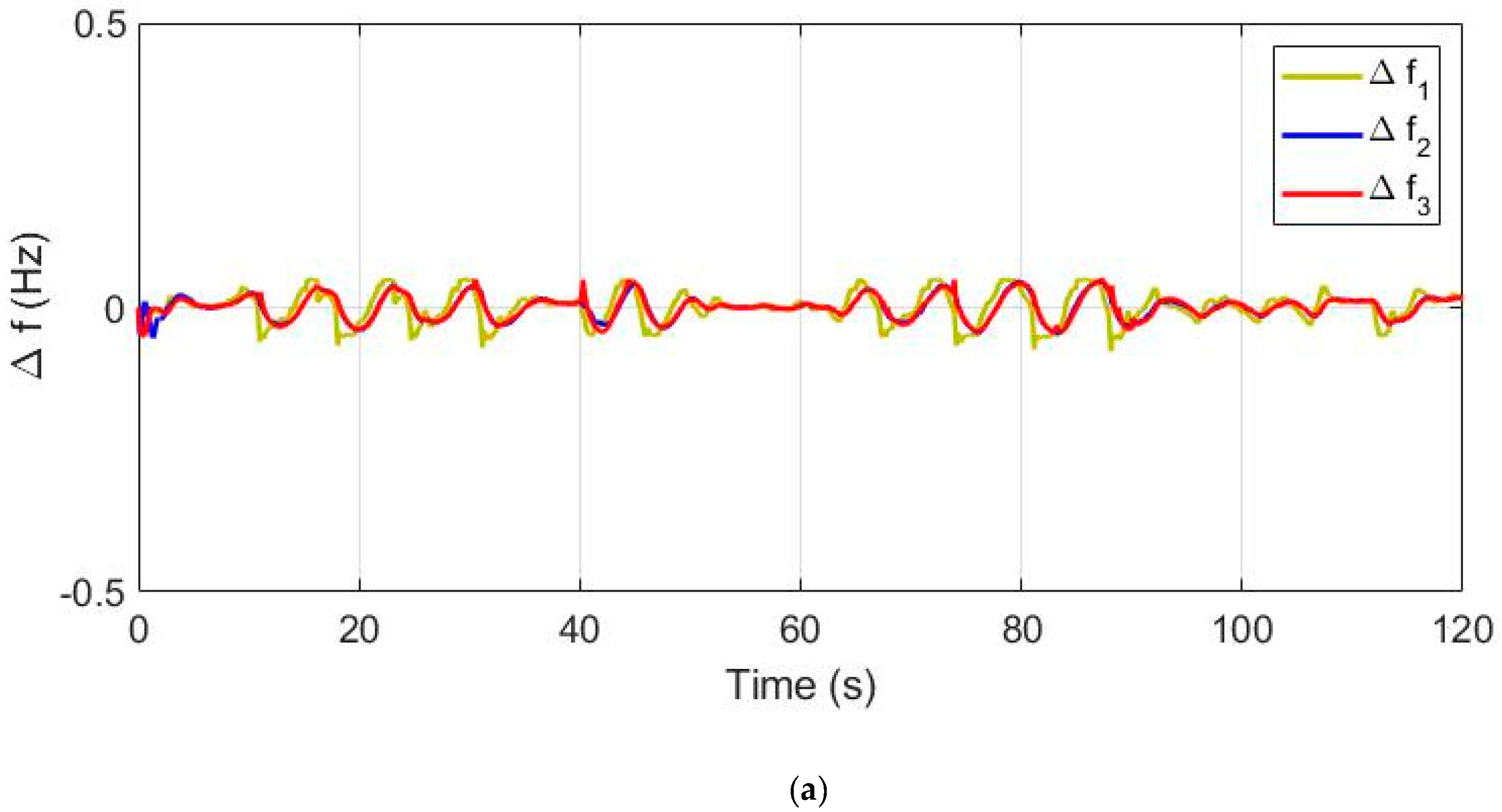
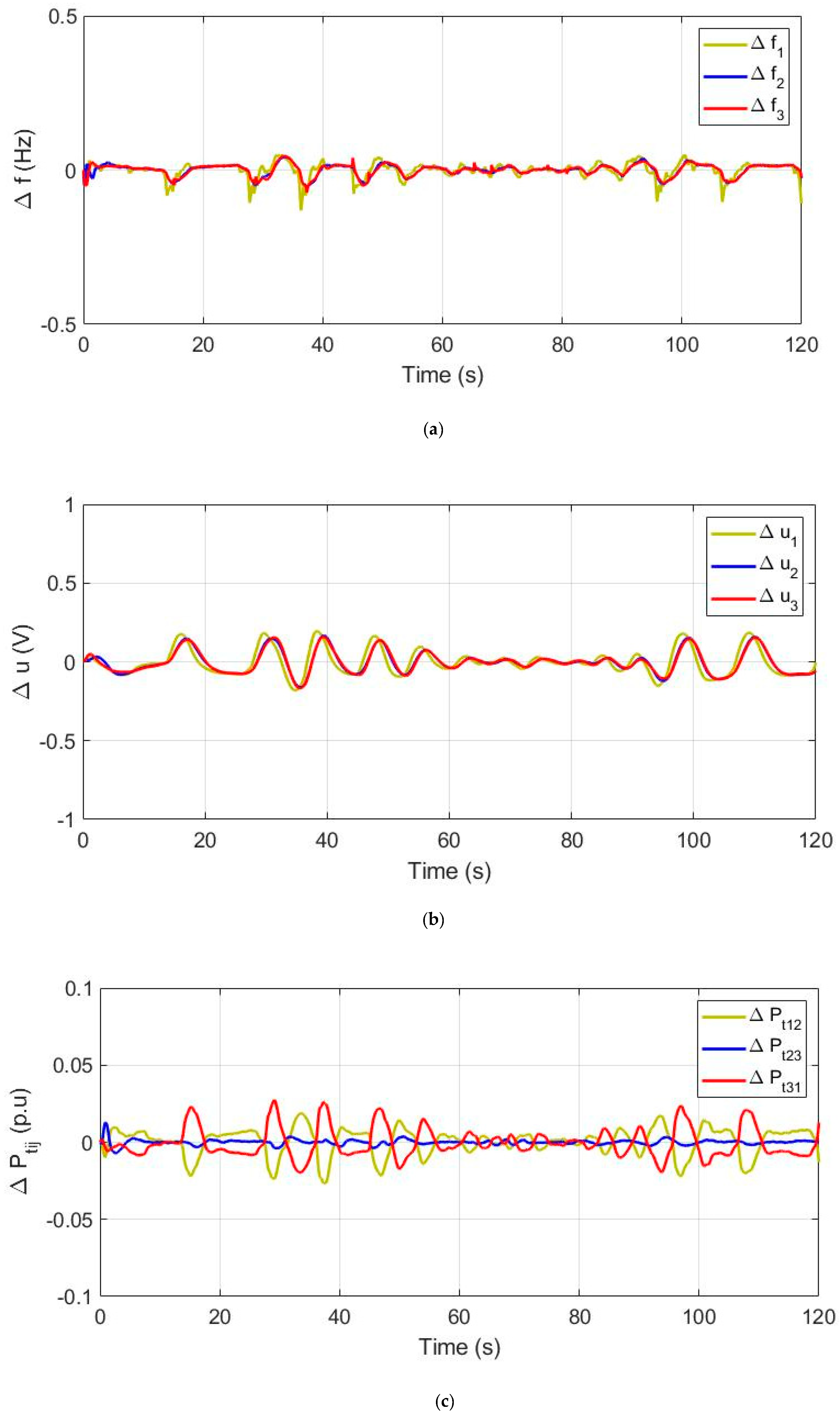
| ∆fi | Frequency deviation (Hz) of ith microgrid. | |
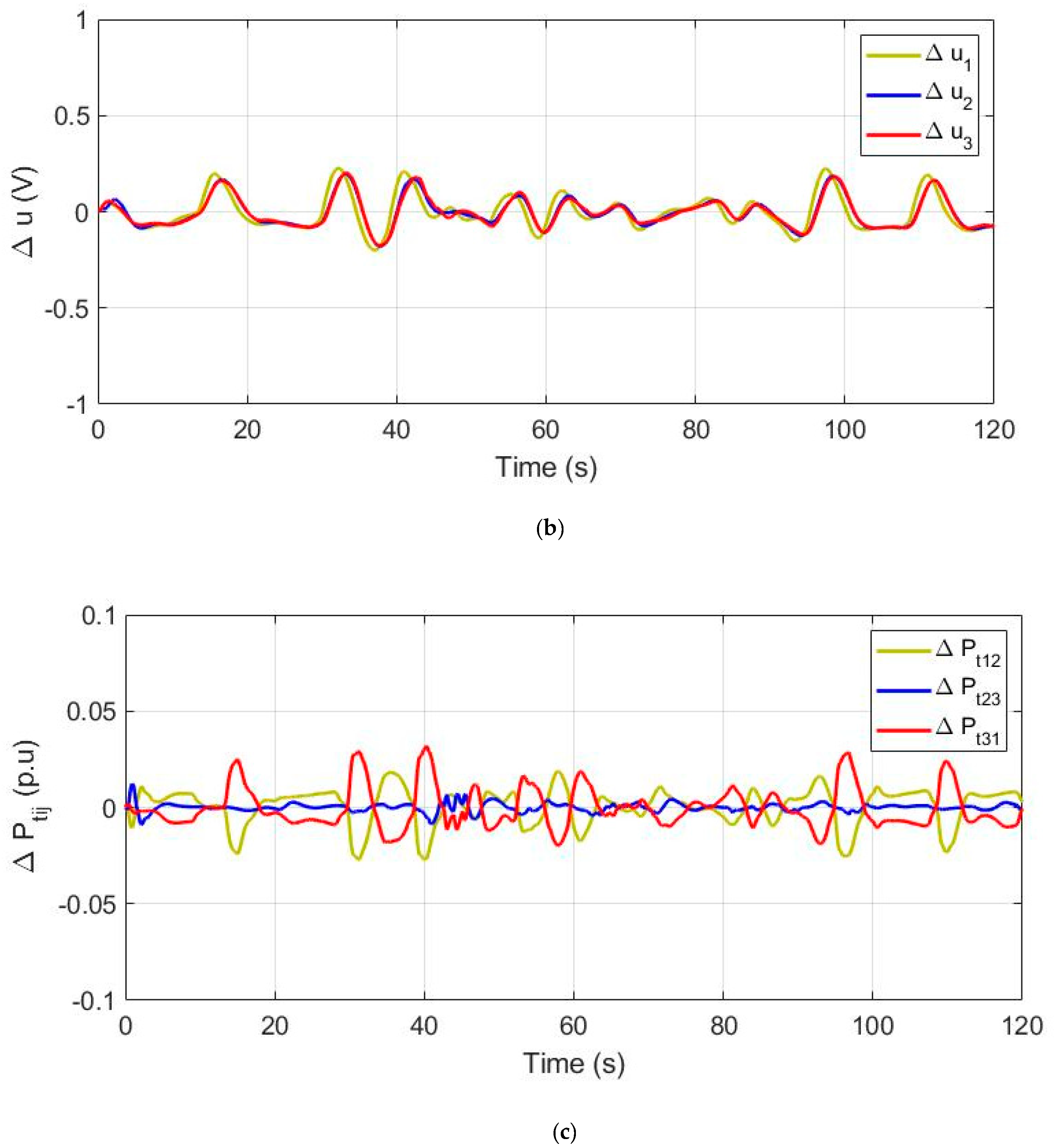
| ∆ui | Voltage deviation (volt) of ith microgrid. | |
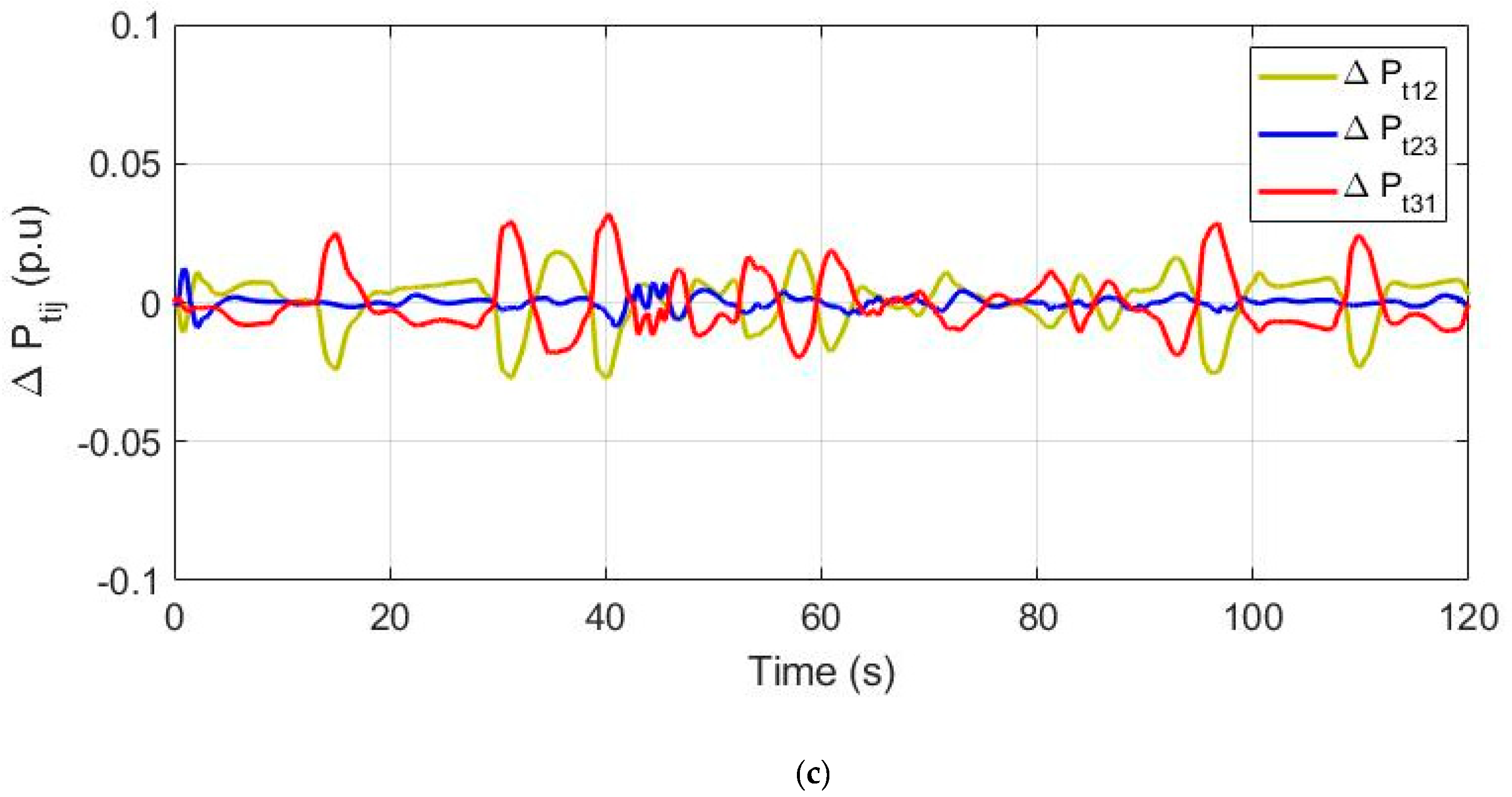
| ∆Ptii | Net tie-line loading on ith microgrid. | |
| Di | Load damping coefficient of ith microgrid. | 0.014, 0.012, 0.010 |
| Mi | Mutual inertia coefficient of ith microgrid. | 0.24, 0.22, 0.20 |
| Ri | Droop coefficient of ith microgrid. | 2.0 |
| Bi | Frequency biasing factor of ith microgrid. | 0.514, 0.512, 0.510 |
| Tij | Coefficient for synchronizing torque. | 0.080 |
| a12, a23, a31 | Inter-grid power transfer ratios | −6/5, −5/4, −4/6 |
| T1, T2, T3, T4, | lead/lag switching delays of converter in VIS system | 0.279 s, 0.026 s, 0.411 s, 0.1 s |
| KBES, TBES | Gain and time constant of BES unit. | 0.003, 0.1 s, |
| KCES, TCES | Gain and time constant of CES unit. | 0.07, 0.9 s, |
| KHEV, THEV | Gain and time constant of HEV unit | 1, 0.02 s |
| KLFR, TLFR, KORC, THX, TST | Gain and time constants of LFR, heat-exchanger and turbine of STP unit. | 5.0, 0.42 s, 0.95, 0.1 s, 0.3 s |
| TPV, TWT | Time constant of SPV and WTG units. | 1.8 s, 1.5 s |
| TCR, TBG, Xc, Yc, bB, TBT | Combustion reaction delay, biogas delay, lead time, lag time, valve actuator and discharge delay of BGTG unit. | 0.01 s, 0.23 s, 0.6,.0 s, 0.05 s, 0.2 s |
| TVA, TBE | Valve and engine delays of BDEG unit. | 0.055 s, 0.5 s |
| THG, TRS, TRH, THT | Time constants of governor, reset, droop, and turbine of MHTG unit. | 0.2 s, 5.0 s, 28.75 s, 1.0 s |
| TBCT, TBSG, TR, KR | Time constants of turbine, governor, and reheat with gain of BCHP unit. | 0.08 s, 0.3 s, 0.3, 10 s |
| KBC, KBG, KMH, KBD, KBE, KCE | Participation factors of BCHP, BGTG, MHTG, BDEG, BES, and CES units. | 0.25, 0.25, 0.25, 0.25, 0.5, 0.5 |
| Ps, K1, K2, K3, K4 | Coupling coefficients of AVR unit. | 0.145, 0.2, −0.1, 0.5, 1.4, |
| KA, TA, KE, TE, KS, TS, KF, TF, KC, TC | Gain and delays of compensators, field, exciter, amplifier, and sensor of AVR unit. | 40, 0.05 s, 1.0, 0.55 s, 1.0, 0.05 s, 0.8 s, 1.4 s, 0.5, 0.715 s |
| USFi, USVi, USTi | Peak undershoots in ∆fi, ∆ui, and ∆Ptii | |
| OSFi, OSVi, OSTi | Peak overshoots in ∆fi, ∆ui, and ∆Ptii. | |
| TSFi, TSVi, TSTi | Settling-times of ∆fi, ∆ui, and ∆Ptii. |
| Algorithm | Specific Parameters | Common Parameters |
|---|---|---|
| PSO | c1 = 1.5; c2 = 2.0; w = 1; wd = 0.99 | Population size, N = 50; Lower bound, lb = 0; Upper bund, ub = 20; Dimensions, dim = 30; Maximum iteration, MaxItr = 100; Simulation time, tsim = 20 s, 120 s. |
| GOA | Cmax = 1; Cmin = 4 × 10⁻⁵; f = 0.5; L = 1.5 | |
| SSA | C2 = rand(); C3 = rand() | |
| SHO | α, β, γ, δ = rand(); Prey_rate = [0.7, 0.9] | |
| QSHO | Jr = 0.25; Rj = rand() | |
| CSHO | Ch1 = rand(); μ = 4.0 | |
| QCSHO | μ = 4.0, Jr = 0.25; Rj = rand() = Ch1; |
| J | ISWAE | IAE | ISE | ITAE | ITSE |
|---|---|---|---|---|---|
| PSO | 0.382 | 1.396 | 0.042 | 7.190 | 0.182 |
| GOA | 0.319 | 1.167 | 0.035 | 6.010 | 0.152 |
| SSA | z0.208 | 1.297 | 0.040 | 6.680 | 0.169 |
| SHO | 0.110 | 1.379 | 0.039 | 7.751 | 0.162 |
| QSHO | 0.091 | 1.426 | 0.043 | 7.343 | 0.185 |
| CSHO | 0.080 | 1.141 | 0.048 | 6.410 | 0.198 |
| QCSHO | 0.012 | 1.076 | 0.020 | 5.544 | 0.088 |
| FOD | I | PI | ID | PD | PID |
|---|---|---|---|---|---|
| JFOD | 48.515 | 2801.299 | 33,576.216 | 2407.723 | 13.205 |
| Gains | Interconnected Microgrids | ||
|---|---|---|---|
| Microgrid1 | Microgrid2 | Microgrid3 | |
| KPi1 | 9.993 | 9.985 | 9.858 |
| KIi1 | 10.084 | 15.142 | 9.998 |
| KDi1 | 9.911 | 10.049 | 10.147 |
| KPi2 | 9.428 | 9.318 | 10.064 |
| KIi2 | 9.997 | 10.012 | 9.942 |
| KDi2 | 10.500 | 9.768 | 10.003 |
| KPi3 | 10.009 | 9.957 | 17.798 |
| KIi3 | 10.230 | 10.193 | 10.028 |
| KDi3 | 10.035 | 2.742 | 10.165 |
| LDRi | 9.978 | 10.055 | 8.237 |
| Cases | Microgrid1 | Microgrid2 | Microgrid3 | JFOD | |||
|---|---|---|---|---|---|---|---|
| VIS | DRS | VIS | DRS | VIS | DRS | ||
| None of SS | 0 | 0 | 0 | 0 | 0 | 0 | 4165.7 |
| Only DRS | 0 | 1 | 0 | 1 | 0 | 1 | 2528.5 |
| VIS in µG3 | 0 | 1 | 0 | 1 | 1 | 0 | 3265.6 |
| VIS in µG2 | 0 | 1 | 1 | 0 | 0 | 1 | 2268.2 |
| VIS in µG2-3 | 0 | 1 | 1 | 0 | 1 | 0 | 2390.5 |
| VIS in µG1 | 1 | 0 | 0 | 1 | 0 | 1 | 3566.1 |
| VIS in µG1-3 | 1 | 0 | 0 | 1 | 1 | 0 | 2363.4 |
| VIS in µG1-2 | 1 | 0 | 1 | 0 | 0 | 1 | 2662.4 |
| Only VIS | 1 | 0 | 1 | 0 | 1 | 0 | 2405.5 |
| Both of SS | 1 | 1 | 1 | 1 | 1 | 1 | 1351.8 |
| Acronym | Full Form | Acronym | Full Form |
|---|---|---|---|
| ALFC | Automatic Load Frequency Control | ITSE | Integral of Time-weighted Square Error |
| AVR | Automatic Voltage Regulator | LFC | Load Frequency Control |
| BCHP | Biomass-fired Combined Heat and Power | LFR | Linear Fresnel Reflector |
| BDEG | Bio-Diesel Engine Generator | LL, NL | Linear Loadings, Non-linear Loadings |
| BEGS | Bio-Energy Generation System | MHTG | Micro-Hydro Turbine Generator |
| BES | Battery Energy Storage | ORC | Organic Rankine Cycle |
| BGTG | Bio-Gas Turbine Generator | PD | Proportional-Derivative |
| CES | Capacitive Energy Storage | PI | Proportional-Integral |
| CLS | Chaotic Linear Search | PID | Proportional-Integral-Derivative |
| CSHO | Chaotic Selfish-Herd Optimization | PSO | Particle Swarm Optimization |
| DRS | Demand Response Support | PTC | Parabolic Trough Collector |
| DSM | Demand Side Management | QCSHO | Quasi-oppositional Chaotic Selfish Herd Optimization |
| ESS | Energy Storage System | QOBL | Quasi Opposition-Based Learning |
| FOD | Figures Of Demerits | RES | Renewable Energy System |
| GOA | Grasshopper Optimization Algorithm | SHO | Selfish Herd Optimization |
| HEV | Hybrid Electric Vehicles | SPV | Solar Photovoltaic |
| I | Integral | SOC | Sate Of Charge |
| IAE | Integral Absolute Error | SSA | Salp Swarm Algorithm |
| ID | Integral-Derivative | SSM | Supply Side Management |
| IRP | Integrated Resource Planning | STP | Solar Thermal Power |
| ISE | Integral Square Error | VIS | Virtual Inertia Support |
| ISWAE | Integral Square of Weighted Absolute Error | WTG | Wind Turbine Generator |
| ITAE | Integral of Time-weighted Absolute Error |
Publisher’s Note: MDPI stays neutral with regard to jurisdictional claims in published maps and institutional affiliations. |
© 2021 by the authors. Licensee MDPI, Basel, Switzerland. This article is an open access article distributed under the terms and conditions of the Creative Commons Attribution (CC BY) license (https://creativecommons.org/licenses/by/4.0/).
Share and Cite
Barik, A.K.; Das, D.C.; Latif, A.; Hussain, S.M.S.; Ustun, T.S. Optimal Voltage–Frequency Regulation in Distributed Sustainable Energy-Based Hybrid Microgrids with Integrated Resource Planning. Energies 2021, 14, 2735. https://doi.org/10.3390/en14102735
Barik AK, Das DC, Latif A, Hussain SMS, Ustun TS. Optimal Voltage–Frequency Regulation in Distributed Sustainable Energy-Based Hybrid Microgrids with Integrated Resource Planning. Energies. 2021; 14(10):2735. https://doi.org/10.3390/en14102735
Chicago/Turabian StyleBarik, Amar Kumar, Dulal Chandra Das, Abdul Latif, S. M. Suhail Hussain, and Taha Selim Ustun. 2021. "Optimal Voltage–Frequency Regulation in Distributed Sustainable Energy-Based Hybrid Microgrids with Integrated Resource Planning" Energies 14, no. 10: 2735. https://doi.org/10.3390/en14102735