Abstract
The present study investigated the natural convection for a hot circular cylinder embedded in a cold square enclosure. The numerical simulations are performed to solve a two-dimensional steady natural convection for three Rayleigh numbers of 103, 104 and 105 at a fixed Prandtl number of 0.7. This study considered the wide range of the inner cylinder positions to identify the eccentric effect of the cylinder on flow and thermal structures. The present study classifies the flow structures according to the cylinder position. Finally, the present study provides the map for the flow structures at each Rayleigh number (Ra). The Ra = 103 and 104 form the four modes of the flow structures. These modes are classified by mainly the large circulation and inner vortices. When Ra = 105, one mode that existed at Ra = 103 and 104, disappears in the map of the flow structures. The new three modes appear, resulting in total six modes of flow structures at Ra = 105. New modes at Ra = 105 are characterized by the top side secondary vortices. The corresponding isotherms are presented to explain the bifurcation of the flow structure.
1. Introduction
The natural convection for internal bodies embedded in an enclosure has, for many years, been studied in detail because of their fundamental significance in heat transfer physics, and its practical importance in many applications such as heat exchangers, electronic equipment cooling, nuclear and chemical reactors, ventilation or passive building cooling, insulating materials, and food processing. The combination of the conditions of the enclosure and the internal bodies provides various reach topics. Thus, numerous studies have dealt with the natural convection for the internal bodies in the enclosure by considering the individual condition or combined conditions such as the thermal boundary [1,2,3,4,5], the shape [3,4,6,7,8,9], 3D effect [2,10,11,12], the size [8,9,11,13,14,15,16,17,18,19,20,21,22], the number of the internal bodies [23], the concentric and eccentric internal body [12,23,24,25,26,27,28,29,30,31,32,33,34,35,36,37,38,39,40], Rayleigh number [1,2,3,4,5,6,7,8,9,10,11,12,13,14,15,16,17,18,19,20,21,22,23,24,25,26,28,29,31,32,33,34,35,36,38,39], Prandtl number [31,40,41], the inclined enclosure [18,22], etc. Recently, comprehensive review on this subject was conducted by Pandey et al. [42]. Also, the research for the heat transfer in the enclosure extends to the nanofluid [43,44,45,46,47]. Among the various combinations, the present study considers the 2D cold enclosure with an internal hot circular cylinder. Thus, the natural convection for an internal cylinder embedded in the enclosure is assumed as the relevant topic.
Shu and Zhu [19] numerically investigated the natural convection in a concentric annulus between a heated inner cylinder and a cold square enclosure. They found that the patterns of flow and thermal fields is significantly affected by the aspect ratio and the Rayleigh number (Ra).
Kim et al. [26] considered the variation of the vertical position of the inner hot cylinder in . They reported that the dependence of the inner vortices and the primary circulation on the vertical position. Later, Yoon et al. [27] extended the research of Kim et al. [26] by considering the higher Ra of 107, showing the occurrence of time dependence.
Hussain and Hussein [28] considered a uniform heat flux as a boundary condition of the inner cylinder alike the problem with Kim et al. [26]. They reported that the effect of a uniform heat flux condition on the Nusselt number in comparison with Kim et al. [26].
Lee et al. [36] considered the change of the cylinder location along the diagonal and horizontal directions in . They revealed that the variation of the mean and local Nusselt numbers accompanying with the modification of the inner cells and the primary circulation according to the cylinder position.
As reviewed above, the natural convection for the internal cylinder in the cavity has been well established by many researches, resulting in greatly improving the understanding of this heat transfer, but based on the authors’ literature survey, the previous studies considered the limited positions of the cylinder for the eccentric effect on the natural convection in the enclosure. Mainly three different directions of the vertical, horizontal, and diagonal direction for the position of the cylinder are dealt with the investigation of the eccentric effect.
Therefore, the main emphasis of the present study is to cover the wide range of the internal cylinder positions to identify the eccentric effect on the thermal and flow structures in the enclosure. The present study classifies the flow structures in the enclosure for the inner cylinder location. Finally, the present study provides the maps for the flow structures to reinforce the understanding of the eccentricity of the cylinder within the enclosure for three Rayleigh numbers. The isotherms are presented to explain the bifurcation of the flow structure. The distributions of the Nusselt numbers for the enclosure are presented as the contours in the polar plane embedded in the enclosure in order to match with the map of the flow structures according to the positions of the inner cylinder center.
2. Numerical Details
Figure 1 presents a schematic of the present system with the side length () of the square enclosure and the cylinder radius of . In order to identify the inner cylinder location, the polar coordinates (, ) are introduced within the enclosure.
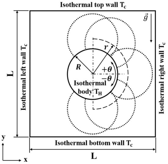
Figure 1.
Computational domain and coordinate system along with boundary conditions.
The origin of the polar coordinate system is the enclosure center. The radial and circumferential positions of the center of the inner cylinder are in the range of with intervals of and with intervals of , respectively. To resolve the diagonal positions, and are also considered. The solutions of the present problems are steady and symmetric about . Thus, we consider the cylinder positions in the right half of the enclosure. In total 106 positions of the inner cylinder are considered in this study.
The constant low temperature (Tc) and high temperature (Th) are put on the enclosure walls and the cylinder surface, respectively. The present study does not consider the radiation which is assumed to be negligible. The Boussinesq approximation is used for the density. The constant assumption is used for the rest of properties. Thus, under the present assumptions, the following continuity, momentum and energy equations satisfying the unsteady incompressible viscous flow and the thermal fields are the dimensionless governing equations:
where, the superscript represents the dimensionless variable. In the above equations, ui are the components of velocity corresponding to the Cartesian coordinates of xi, p is the pressure, t is the time and T is the temperature. The dimensionless variables in the above equations are defined as:
where, α and ρ denote the thermal diffusivity and the density, respectively.
The non-dimensionalization results in dimensionless parameters of Rayleigh number, and Prandtl number, Pr = ν/α, where β, g and ν are the expansion coefficient, the gravitational acceleration and the kinematic viscosity, respectively. The value of Pr is 0.7 which corresponds to the air. The present study considers three values of Ra of 103, 104 and 105.
For the discretization of the space, a second-order central difference scheme is utilized to structured grids, based on the finite volume method (FVM). A second-order implicit scheme is employed for temporal discretization. The Crank-Nicolson scheme and the second-order Adams-Bashforth are adopted for the diffusion and convection terms, respectively. A two-step, time-split scheme is used for the time advance of the flow and thermal fields. The solution of Poisson equation satisfies the continuity equation. Further details of this scheme are can be referred from Kim and Moin [48] and Zang et al. [49]. We derived the governing equations using a generalized curvilinear coordinate system.
The boundary conditions of the no-penetration and no-slip are imposed on the walls for the flow. As the wall boundaries for the energy equation, the hot and cold isothermal conditions are defined for the internal cylinder and the enclosure, respectively.
After achieving the velocity and temperature, the local and surface-averaged Nusselt numbers are obtained by following definitions;
where n and A are the normal direction to the wall and the surface area.
Figure 2 shows the present grid system. The present computations use the grid numbers of 201 × 201 in the horizontal (x) and vertical (y) directions. The non-uniform grid distribution is generated by using the algebraic function to resolve the high gradients near the walls. Particularly, the dense resolution of the grid is maintained by tuning the grid points to cover the variation of the cylinder position. The test of the grid dependence is performed by using coarser and much finer grids of 102(x) × 102(y), 303(x) × 303(y) and 402(x) × 402(y). The difference of Nusselt numbers between grid numbers becomes smaller, which is less than 0.5%, 0.1% and 0.07% for the coarse, medium and fine grids. Finally, the grid resolution of 201(x) × 201 (y) is used in all commutations for the computational efficiency.
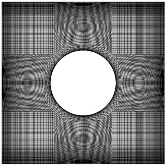
Figure 2.
A typical grid distribution for .
The convergence criteria is 105. The present study adopts the variable time step in order to meet the numerical stability condition of the Courant–Friedrichs–Lewy condition (CFL), CFL ≤ 0.3, for all calculations.
For the validation of the present numerical methods, the surface-averaged Nusselt numbers of the inner cylinder for different values of Ra are compared with those of Park et al. [18], Kim et al. [26] and Lee et al. [36], as presented in Table 1. The present results agree well with the previous researches.

Table 1.
Comparison of surface-averaged Nusselt number at hot wall from this study with those of previous numerical studies.
In addition, in order to identify the reliability of the present numerical methods to achieve the solutions of the eccentricity between the enclosure and the cylinder, the previous results [26,40] for total surface-averaged Nu of the square enclosure () and the inner circular cylinder () for the vertical variation are considered. The present results agree well with the previous results [26,40], as presented in Figure 3.
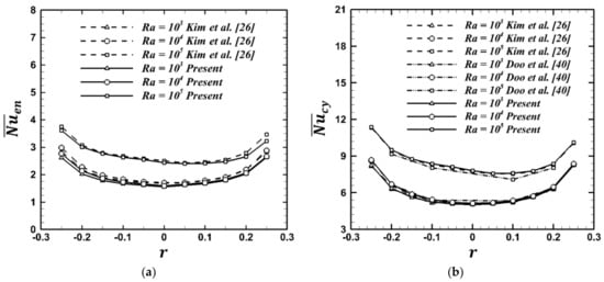
Figure 3.
Comparison of present results of total surface-averaged Nusselt number with Kim et al. [26] and Doo et al. [40]: (a) the square enclosure, and (b) the inner circular cylinder, .
3. Results and Discussion
3.1. Map and Patterns of Flow and Thermal Fields
The map is introduced to show the patterns of thermal and flow fields in the (r, θ) plane which covers the inner cylinder positions. In order to reinforce the understanding of the eccentricity of the cylinder within the enclosure, the (r, θ) plane for the map is inserted in the enclosure, as shown in Figure 4.
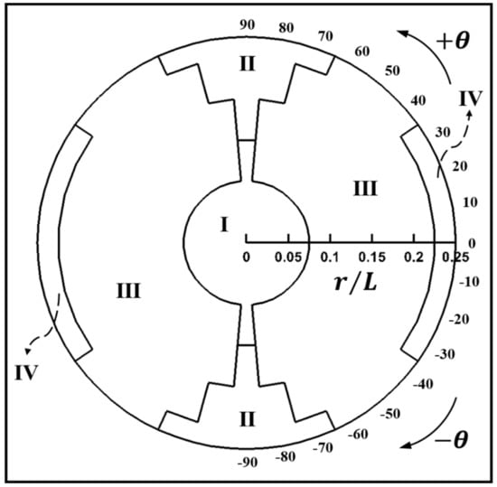
Figure 4.
Map of the flow structure for Ra = 103.
3.1.1. Ra = 103
Figure 4 show the map of the flow structures for Ra = 103. The flow structures are classified based on the formation of the streamlines. At low this Ra, the conduction mode is predominant to the heat transfer in the enclosure. The map of the flow structures for Ra = 103 is a four-fold symmetry about the horizontal and vertical center lines at y = 0 and x = 0, respectively.
In general, the Mode I covers the circular formation with the enclosure center and extends to the upper and lower narrow areas long the vertical center line. At the enclosure center of r = 0 and θ = 0°, the isothermal lines are almost linearly distributed along the radial direction. The corresponding streamlines reveal two inner vortices embedded in two symmetric circulations, as presented in Figure 5a. Therefore, Mode I reveals two overall rotating primary eddies and each rotating eddy has two inner vortices (TPE_TIV).
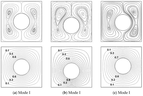
Figure 5.
Streamlines (upper row) and isotherms (lower row) at (a) (r = 0, θ = 0°), (b) (r = 0.1L, θ = −90°) and (c) (r = 0.05L, θ = 30°) for Ra = 103.
When the internal cylinder positioned below the horizontal center of and moves to lower boundary of Mode I, the area between the bottom wall and the cylinder becomes narrow. Thus, the size of lower inner vortex is reduced gradually, but the upper inner vortex is getting bigger. The corresponding isotherms is getting denser in the region between the bottom wall and the inner cylinder, as shown in Figure 5b for (r = 0.1L, θ = −90°). The thermal and flow fields for (r = 0.1L, θ = 90°) are symmetric with those for (r = 0.1L, θ = −90°). This variation of each fields in Mode I is consistent with the findings of Kim et al. [26].
In Mode I, in order to investigate the effect of the circumferential position on the thermal and flow fields, the variation of the circumferential direction is considered from the vertical center line (θ = 90° and θ = −90°) to the horizontal center line (θ = −0°). When θ approaches counterclockwise from θ = −90° to θ = 0° within Mode I, the two inner vortices in the left and right primary counter-clockwise eddies become smaller and larger, respectively, as shown in Figure 5c for θ = −30°. Consequently, when θ approaches counterclockwise from θ = −90° to θ = 0°, the distance between the right wall and inner cylinder enclosure becomes shorter. Thus, the gradient of isotherms augments, as the primary eddy becomes smaller in the right side. When θ approaches clockwise from θ = 90° to θ = 0° within Mode I, the thermal and flow fields undergo the symmetric pattern about the horizontal center line at y = 0 to those for the counterclockwise rotation from θ = −90° to θ = 0°.
When the inner cylinder gets away from the boundary of Mode I for (r = 0.1L, θ = 90°) and move downward and upward, two inner vortices are merged into the primary eddy at (r = 0.15L, θ = 90°) in Figure 6a and (r = 0.15L, θ = −90°) which is symmetry to (r = 0.15L, θ = 90°). Therefore, Mode II reveals two overall rotating primary eddies (TPE). The area of Mode II become wider in the circumferential direction with increasing the redial position of the inner cylinder center. The critical circumferential locations for the radial positions of r = 0.2L and r = 0.25L are θ = 80° and θ = 70°, respectively, as shown in Figure 4 for the Map. Thus, as the radial position increases, the critical circumferential location, where the flow structure changes, decreases.

Figure 6.
Streamlines (left column) and isotherms (right column) at (a) (r = 0.15L, θ = 90°), (b) (r = 0.25L, θ = 70°) for Ra = 103.
The effect of the cylinder radial position is that the core of the primary circulation moves toward the same direction of the variation of the internal cylinder location because the enclosure can secure spaces opposite the inner cylinder moving enough to enlarge the core of the circulation. When r increases within Mode II, isotherms become denser in between the cylinder and the enclosure wall facing to the cylinder, otherwise isotherms are getting sparser in the opposite region.
In Mode II, the effect of the circumferential position on the flow and thermal fields is almost the same as Mode I. When the inner cylinder rotates clockwise from θ = 90° to θ = 70° within Mode II, the space in the direction of the inner cylinder rotating becomes small, as shown in Figure 6b. As a result, in this space, the primary circulations are squeezed and small. The isotherms form dense and coarse gradients in the cylinder side and opposite regions, respectively. The counter-clockwise rotation from θ = −90° to θ = −70° within Mode II undergoes the same variation as the clockwise rotation from θ = 90° to θ = 70°.
When the inner cylinder gets away from the boundary of Mode I for (r = 0.1L, θ = 90°) and rotates clockwise from θ = 90° to θ = 80°, in the left side of the enclosure, two secondary inner eddies at (r = 0.1L, θ = 90°) is merged into the primary eddy at (r = 0.1L, θ = 80°), as shown in Figure 7a. When θ continuously turn clockwise from θ = 80° to θ = 0°, the center of the merged inner vortex in the left circulation rotates clockwise, as shown in Figure 7a,b for θ = 80° to θ = 80°, respectively. Simultaneously, in the right primary eddy, the upper inner vortex becomes bigger and the lower inner vortex squeezes into the clockwise direction.

Figure 7.
Streamlines (left column) and isotherms (right column) at (a) θ = 80° and (b) θ = 0° at a fixed r = 0.1L for Ra = 103.
Therefore, Mode III reveals two overall rotating primary eddies which have two inner vortices in the primary circulation in the direction of the inner cylinder rotation and one inner vortex in the opposite primary circulation (TPE_TOIV). When the inner cylinder gets away from the boundary of Mode II holding TPE, the primary circulation in the inner cylinder rotating direction contains additional inner vortex. When the inner cylinder circumferentially approaches to the horizontal center (θ = 0°), this additional inner vortex becomes bigger and the lower inner vortex squeezes into the clockwise direction. When θ approaches counter-clockwise from θ = −90° with the negative sign in the lower half of the enclosure to θ = 0° within Mode III, the flow and thermal fields undergo the symmetric pattern about the horizontal center line to those for the clockwise rotation from θ = 90° to θ = 0°.
When the position of the inner cylinder changes along the radial direction, gets away from the boundary of Mode II and enters into Mode IV, the primary eddy in the direction of the cylinder moving are divided in Figure 8 for r = 0.1L and θ = 0°. Also, when the inner cylinder rotates along the circumferential direction, gets away from the boundary of Mode III and enters into Mode IV, two inner vortices in the primary eddy are divided in the direction of the inner cylinder rotation. Therefore, Mode IV reveals one overall rotating primary eddy and two divided vortices (OPE_TDV).
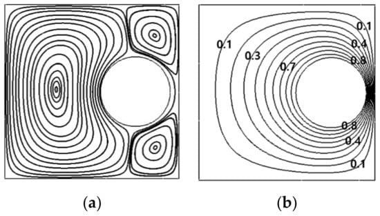
Figure 8.
Streamline (a) and isotherm (b) at (r = 0.25L, θ = 0°) in Mode IV for Ra = 103.
3.1.2. Ra = 104
The isothermal lines and streamlines at Ra = 104 have almost the same formations as those at Ra = 104. For each mode, the effects of the radial and circumferential locations of the internal cylinder center on the thermal and flow fields at Ra = 104 are very similar to those at Ra = 104. Thus, the map of the flow structures for Ra = 104 consists with the same four modes of Mode I, Mode II, Mode II and Mode IV corresponding to TPE_TIV, TPE, TPE_TOIV, and OPE_TDV, respectively, as Ra = 103. However, the buoyance in the direction of the gravity gives a greater effect on both fields, because of the augmentation of the convection. Thus, in contrast to Ra = 103 having a four-fold symmetry, the map for Ra = 104 is a two-fold symmetry , as presented in Figure 9.
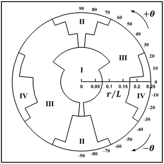
Figure 9.
Map of the flow structure for Ra = 104.
In general, the Ra = 104 case forms thinner thermal boundary layer on the cylinder bottom than the upper side, and a smaller and weaker inner lower vortex than the upper one, comparing to Ra = 103. The regions of Modes I, II and IV for Ra = 104 are larger than the regions of corresponding Modes for Ra = 103, as shown in Figure 4 and Figure 9, respectively.
As the cylinder is positioned downward from the enclosure at r = 0 along the vertical center line at θ = −90°, two internal vortices merges at r = 0.1L. Namely, Mode I changes into Mode II, which is earlier than r = 0.15L at Ra = 103. In Mode II, as r increases at θ = −90°, isotherms becomes distorted and the thermal plumes on the cylinder top is getting bigger.
As the cylinder is located upward at θ = 90°, the occurrence of the bifurcation from Mode I to Mode II at r = 0.15L is later than that for the downward movement of the cylinder, due to the stronger convective flow in the space between the top wall and the cylinder.
In Mode II formation, when the cylinder is positioned further upward, the two overall rotating primary eddies are more obligated than the downward movement of the cylinder, as observed in Figure 10b,c. These present results for the vertical eccentric effect of the cylinder on the isotherms and streamlines are consistent with Kim et al.’s [26] ones.
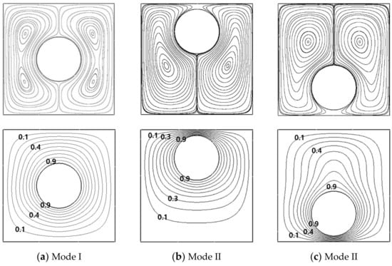
Figure 10.
Streamlines (upper row) and isotherms (lower row) at (a) (r = 0, θ = 0°), (b) (r = 0.25L, θ = 90°) and (c) (r = 0.25L, θ = −90°) for Ra = 104.
The variation of the circumferential position of the cylinder for Ra = 104 gives a similar effect on the natural convection as Ra = 103. But, the sizes of the Modes for Ra = 104 are different with those for Ra = 103. When the inner cylinder rotates clockwise from θ = 90° to θ = 0° at r = 0.1L in the upper region, the flow structures changes from Mode I to Mode III, as shown in θ = 90°, θ = 30° and θ = 0° in Figure 11a–c, respectively, where the critical angle for the bifurcation of flow structures is θ = 30°. However, when the inner cylinder rotates counter-clockwise from θ = −90° to θ = 0° at r = 0.1L in the lower region, the flow structures changes from Mode I to Mode III, as shown in θ = −80° in Figure 11d, where the critical angle is θ = −80°.
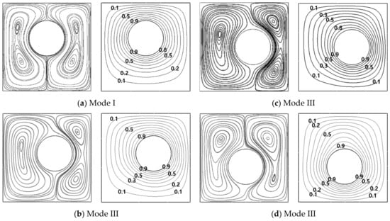
Figure 11.
Streamlines (left column) and isotherms (right column) at (a) θ = 90°, (b) θ = 30°, (c) θ = 0° and (d) θ = −80° at a fixed r = 0.1L for Ra = 104.
At r = 0.2L and r = 0.25L, the flow structures undergo three modes by the effect of the circumferential eccentricity of the cylinder. At r = 0.2L, when the cylinder rotates clockwise from θ = 90° to θ = 0°, Mode II changes into Mode III at θ = 70° and then the bifurcation from Mode III to Mode IV occurs at θ = 0°, as presented in Figure 12a–c, respectively. When the internal cylinder rotates counter-clockwise from θ = −90° to θ = 0°, Mode II changes into Mode III at θ = −70° and then the bifurcation from Mode III to Mode IV occurs at θ = −20°, as presented in Figure 12d–f, respectively.
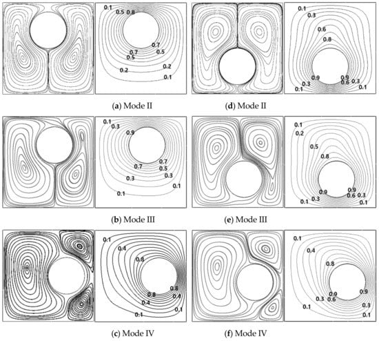
Figure 12.
Streamlines (left column) and isotherms (right column) at (a) θ = 90°, (b) θ = 70°, (c) θ = 0° (d) θ = −90°, (e) θ = −70° and (f) θ = −20° at a fixed r = 0.2L for Ra = 104.
At r = 0.25L, when the inner cylinder rotates, the bifurcation from Mode II to Mode III occurs later than that at r = 0.2L, resulting in that the size of Mode II at r = 0.25L is wider than that at r = 0.2L, as observed in Figure 9 for the Map. In comparison with Ra = 103, the region for Mode IV enlarges when Ra = 104.
3.1.3. Ra = 105
When Ra = 105, the Mode I with TPE_TIV, existed at Ra = 104 and 104, disappears in the map of the flow structures, as shown in Figure 13. The new three modes of V, VI and VII appear. The Mode I is divided into about the four modes of II, III, V, VI and VII.
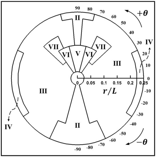
Figure 13.
Map of the flow structure for Ra = 105.
The center of the enclosure is occupied by Mode II, since a stronger buoyancy makes merging the lower inner vortex into the upper vortex of Mode I which is existed at Ra = 103 and 104. Therefore, the centers of the overall rotating eddies locate at the upper half of the enclosure and the upward thermal plume is originated from the internal cylinder in Figure 14a.


Figure 14.
Streamlines (left column) and isotherms (right column) at (a) (r = 0, θ = 0°), (b) (r = 0.25L, θ = −90°), (c) (r = 0.05L, θ = 90°) and (d) (r = 0.15L, θ = 90°) for Ra = 105.
The radial eccentricity by the cylinder downward movement along the vertical centerline from (, ), the Mode II keep maintains, as shown Figure 14b for , respectively. As the cylinder moves downward from the enclosure center, the circulation is getting larger in the upper half of the enclosure and the upward thermal plume is more elongated, since wider area between the bottom wall and the cylinder secures a stronger convection in the upper half of the enclosure.
The upward movement of the cylinder from (r = 0, θ = 90°) contributes to the presence of the new Mode V in the Map of the flow structure in Figure 13. When the cylinder moves upward from the enclosure center, the mode changes from Mode II to Mode V and then recovers again Mode II, which is clearly identified in Figure 14c,d for r = 0.05L and r = 0.15L, respectively.
In the range of 0.05L ≤ r ≤ 0.1L corresponding to Mode V in the map, a fair of secondary vortices appears in the cylinder upper surface. Therefore, Mode V presents two overall rotating primary eddies and secondary two vortices (TPE_STV). The corresponding isothermal lines exhibit that one upward plume in Mode II is divided into two plumes from the cylinder and one downward plume from the enclosure top wall, respectively, as presented in Figure 14c.
As the cylinder moves further upward from r = 0.1L to r = 0.25L, the area between the enclosure top wall and cylinder is not enough to activate the secondary two vortices in this Ra = 105. In other words, the buoyance force is not enough to overcome the conduction and to keep the convection to maintain the secondary two vortices in this narrow space at this Ra = 105. Thus, the secondary two vortices disappear, as shown in Figure 14d for r = 0.15L. Mainly, the isotherms are linearly distributed in this narrow region between the enclosure top wall and cylinder. As a result, Mode V changes into Mode II.
The circumferential eccentricity by the clockwise rotation of the cylinder from (r = 0.05L, θ = 90°) to the horizontal center line (r = 0.05L, θ = 0°) leads to two bifurcations from Mode V to Mode VI and from Mode VI to Mode III, as shown in Figure 13. When θ = 70° at r = 0.05L, the upper secondary vortices still appear, but these secondary vortices become asymmetric, since the left upper secondary vortex is squeezed and smaller by the augmentation of the left primary eddy due to the enlargement of the left upper region by the clockwise rotation of the cylinder. Particularly, the right primary eddy contains additional tiny lower inner vortex by the compression of the clockwise rotation of the cylinder, as presented in Figure 15a.
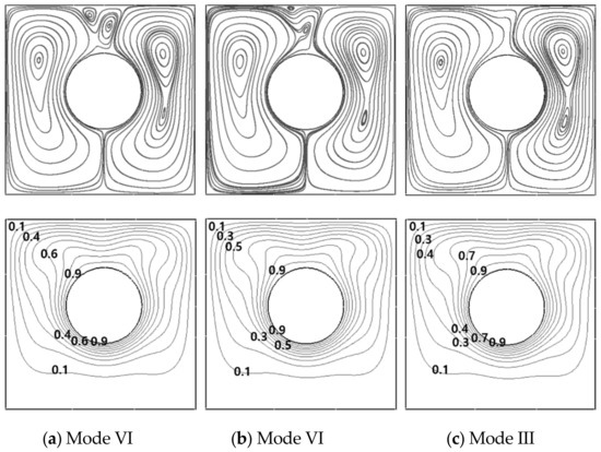
Figure 15.
Streamlines (upper row) and isotherms (lower row) at (a) θ = 70°, (b) θ = 60° and (c) θ = 50° at a fixed r = 0.05L for Ra = 105.
As a result, Mode VI forms secondary two vortices and two overall rotating primary eddies which have two inner vortices in a large circulation in the direction of the inner cylinder rotation and one inner vortex in the opposite primary circulation. Finally, Mode VI is named as TPE_TOIV_STV. When the inner cylinder clockwise rotates from θ = 70° to θ = 50° at r = 0.05L, the upper secondary vortices becomes smaller but the lower inner vortex in the right primary eddy becomes bigger at θ = 60° in Figure 15b, and then the upper secondary vortices disappears at θ = 50° in Figure 15c. Therefore, at θ = 50°, the bifurcation from Mode VI to Mode III occurs. The Mode III maintains up to θ = 0°.
At r = 0.1L, the circumferential eccentricity by the cylinder clockwise rotating from θ = 90° to the horizontal center line of θ = 0° leads to three bifurcations from Mode V to Mode VI, from Mode VI to Mode VII, and from Mode VII to Mode III, as shown in Figure 13 for the Map.
At r = 0.1L, when the inner cylinder clockwise rotates from θ = 90° to θ = 60°, first bifurcation from Mode V to Mode VI occurs, as shown in Figure 16a. When θ = 45°, the left upper secondary vortex disappears and simultaneously the right upper secondary vortex becomes smaller, as shown in Figure 16b. Thus, new flow structure forms in Mode VII where one secondary upper vortex in company with TPE_TOIV. The Mode VII is defined as TPE_TOIV_SOV. When the inner cylinder reaches to θ = 40°, the right upper secondary vortex also disappears, as shown in Figure 16c, resulting in Mode III which maintains to θ = 0°.
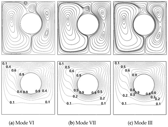
Figure 16.
Streamlines (upper row) and isotherms (lower row) at (a) θ = 60°, (b) θ = 45° and (c) θ = 40° at a fixed r = 0.1L for Ra = 105.
At r = 0.15L, the clockwise rotation of the inner cylinder from θ = 90° to θ = 0° derives three bifurcations from Mode II to Mode III, from Mode III to Mode VII, and from Mode VII to Mode III, as shown in Figure 14 for the Map. At this radial location, Mode II at θ = 90° changes into Mode III at θ = 80°, and the lower inner vortex of the primary eddy in the rotational direction becomes bigger at θ = 70°, as shown in Figure 17a for θ = 80°.
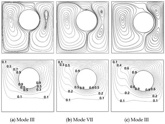
Figure 17.
Streamlines (upper row) and isotherms (lower row) at (a) θ = 80° (b) θ = 60° and (c) θ = 40° at a fixed r = 0.15L for Ra = 105.
When θ = 60° at r = 0.15L, the secondary tiny vortex appears on the cylinder upper surface and it exists up to θ = 45° under the main flow structure of Mode III, as shown in Figure 17b for θ = 60°. The primary circulation in the opposite direction to the rotation of the cylinder strongly turns around the inner cylinder surface in the opposite side circulation, as the inner cylinder rotates clockwise from θ = 90°.
When θ = 40° at r = 0.15L, the secondary tiny vortex disappears by the augmentation in size and strength of the upper inner vortex of the primary eddy in the opposite direction to the rotation of the inner cylinder, resulting in Mode III which is preserved up to θ = 0°, as shown in Figure 17c at θ = 40°. Therefore, at r = 0.15L, the third bifurcation from Mode VII to Mode III occurs at θ = 40°.
At r = 0.2L, when the inner cylinder rotates clockwise from θ = 90° to θ = 0° and counterclockwise from θ = −90° to θ = 0°, single bifurcation from Mode II to Mode III occurs at θ = 80° and θ = −60°, respectively, as shown in Figure 13 for the Map.
At r = 0.25L, when the inner cylinder rotates clockwise from θ = 90° to θ = 0°, two bifurcations occur, as shown in Figure 13. First bifurcation from Mode II to Mode III occurs at θ = 70°, as shown in Figure 18a for θ = 70°. The second bifurcation from Mode III to Mode IV occurs at θ = 20° and Mode IV preserves up to θ = 0°, as shown in Figure 18b for θ = 20°.

Figure 18.
Streamlines (left column) and isotherms (right column) at (a) θ = 70° and (b) θ = 20° at a fixed r = 0.25L for Ra = 105.
At r = 0.25L, the counter-clockwise rotation from θ = −90° to θ = 0° provides two bifurcations, as shown in Figure 13. First bifurcation from Mode II to Mode III occurs at θ = −60°, as shown in Figure 19a. The second bifurcation from Mode III to Mode IV occurs at θ = −30°, as shown in Figure 19b.

Figure 19.
Streamlines (left column) and isotherms (right column) at (a) θ = −60° and (b) θ = −30° at a fixed r = 0.25L for Ra = 105.
The circumferential eccentricity by the counter-clockwise rotation from θ = −90° to θ = 0° in the lower half leads to almost the same distribution of isotherms, regardless of the radial position. At θ = −90°, the isotherms form upward and large plume appears on the cylinder, which forms sharper thermal gradient near the enclosure top. The dense isotherms form over the lower surface of the cylinder due to the increased buoyance with increasing Rayleigh number. The stagnant area under the cylinder becomes wider with augmenting r, resulting in very coarse isotherms. When the inner cylinder rotates counter-clockwise from θ = −90° to θ = 0°, the upward thermal plume inclines to the cylinder rotational direction.
3.2. Nusselt Number
The distributions of the surface—averaged Nusselt numbers () for each walls of the enclosure are presented as the contours in the (r, θ) plane in the (r, θ) plane embedded in the enclosure in order to match with the map of the flow structures according to the positions of the cylinder center, as presented in Figure 20.
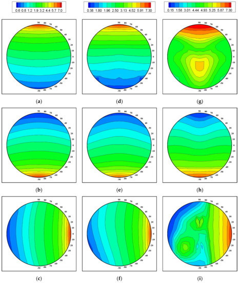
Figure 20.
Contours of the top [1st row, (a,d,g)], bottom [2nd row, (b,e,h)] and right [3rd row, (c,f,i)] surface-averaged Nusselt numbers for Ra = 103 (1st column), 104 (2nd column) and 105 (3rd column).
For Ra = 103, the gap between the surface of the enclosure wall and the cylinder is predominant to the change of , as shown in Figure 20a–c for the top, bottom, right walls of the enclosure, respectively. The for the bottom and top walls are dependent on nearly the vertical direction, as shown in Figure 20a,b, respectively, due to the strong conduction at low Ra = 103. Because the upward movement of the cylinder forms denser and coarser isotherms near the top and bottom walls, respectively, the larger and smaller values of for the top and bottom walls appear at θ = 90° and θ = −90° for r = 0.25L. The cylinder downward movement derives the opposite patterns of for the bottom and top walls to the upward movement.
At this low Ra = 103, the right wall exhibits the symmetric distribution of about the center line of x = 0, observed in Figure 20c. The values of for the right wall is dependent on nearly the horizontal direction. Therefore, the distribution of is composed of almost the vertical lines. However, the careful observation identifies the very weak curvature of the contours which means the existence of the weak convection at low Ra = 103. The magnitude of for the right wall is governed by the distance between the enclosure wall and the cylinder surface, like that for the bottom and top walls.
For Ra = 104, the distributions of for the enclosure walls are almost the same as Ra = 103, which is consistent with the similar maps for the thermal and flow structures for Ra = 104 and Ra = 103. Therefore, the for the bottom and top walls depend on mainly the vertical distance and form the horizontal lines based contours, as presented in Figure 20d,e. The for the right wall is dependent on nearly the horizontal direction. Thus, the distribution of is composed of almost the vertical lines, as shown in Figure 20f. However, the increase of the convection with augmenting Ra from 103 and Ra = 104 contributes the contours of to be more curvature.
As Ra becomes large to Ra = 105, the distributions of for the walls of the enclosure considerably change in comparison with those for lower Ra = 103 and Ra = 104, which can be clarified in Figure 20g–i,a–c and d–f for Ra = 105, Ra = 103 and Ra = 104, respectively.
As discussed in the thermal and flow structures, when Ra = 105, the large upward thermal plume form the cylinder upper surface characterizes these fields due to the increase of the buoyance. Therefore, the magnitudes of for the top wall becomes much bigger than those for lower Ra = 103 and Ra = 104.
As the cylinder moves upward along the centerline from (r = 0.25L, θ = −90°) which is the nearest cylinder position to the bottom wall, the for the top wall increases, decreases and increases again. The increase of according the upward movement of the cylinder from (r = 0.25L, θ = −90°) is attributed to the combined effects of the augmentation of the conduction due to the reduction gap between the cylinder and the top wall and a stronger convection generating the large upward thermal plume. As the cylinder keeps moving upward, the value of decreases by the slightly weaken convection due to a smaller area between the cylinder and the top wall. Also, the downward plume from the top wall of the enclosure, corresponding to the secondary vortices over the upper surface of the inner cylinder, contributes to the decrease of for the top wall. Finally, as the internal cylinder continuously moves upward, the increases and reaches to the maximum.
When the cylinder becomes far away, the upward thermal plume inclines and forms coarse isotherms near the top wall. Therefore, this inclined thermal plume contributes the value of for the top wall to the reduction. The small distribute around the outer boundary of the position of the inner cylinder, as presented in Figure 20g.
As the cylinder locates in the lower half of the enclosure for Ra = 105, the distribution of for the bottom wall is similar to that for lower Ra = 103 and Ra = 104. Namely, when inner cylinder moves upward from (r = 0.25L, θ = −90°) to the enclosure center (r = 0, ), the decreases, as shown in Figure 20h. Otherwise, when the inner cylinder locates in the upper half for Ra = 105, the variation of is very weak with a small value, since the thermal stratification appears in the area under the cylinder, as early observed in the isotherms.
As the cylinder locates in the right half of the enclosure for Ra = 105, the for the right wall depends on mainly the gap between the right wall and cylinder, resulting in the same increasing pattern of with closer to the right wall as lower Ra = 103 and Ra = 104, as observed in Figure 20i. Otherwise, as the cylinder locates in the left half of the enclosure, the coarse isotherms form the opposite corners. Hence, the small s for the right wall appear as the cylinder positions near the left bound of the position of the cylinder.
Figure 21 shows the total surfaces-averaged Nusselt number of enclosure, , in the present ranges of the radial and circumferential locations of the inner cylinder center for different Ra. The Ra = 103 and form about the same distribution of , which is almost the four-fold symmetry about x = 0 and y = 0, as presented in Figure 21a,b, respectively. As discussed in the thermal and flow fields, because the gap is predominant to the heat transfer, has large values at the horizontal and vertical boundaries of the cylinder position. In other words, the magnitude of is mainly as a function of the radial direction at these low Ra of 103 and 104. For the validation in Figure 3, has a parabolic profile according to r, regardless of θ.
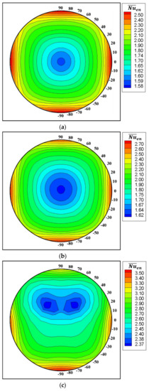
Figure 21.
Total surface-averaged Nusselt number of the enclosure for (a) Ra = 103, (b) Ra = 104 and (c) Ra = 105.
As Ra increases to 105, the location of the minimum of moves diagonally upward from the center of the enclosure (x = 0, y = 0) where the minimum of occurs at Ra = 103 and 104 in Figure 21c. In the regions showing the minimum of , the inclined rising thermal plumes on the upper surface of the cylinder form the secondary vortices which accompany the down welling plume from the top wall of the enclosure. This down welling plume derives the coarse isotherms near the enclosure top wall, which contributes to forming regions containing the minimum of . The value of near the bottom are bigger than that those near the top wall, because the stagnant region at the top wall becomes wider than that near the bottom.
4. Conclusions
The present study researched the natural convection in a cold square enclosure with a hot circular cylinder. The numerical simulations are performed to solve a 2-D unsteady natural convection for Ra of Ra = 103, 104 and 105 at Pr = 0.7.
This study covered the wide range of the cylinder positions to identify the eccentric effect of the inner cylinder on flow and thermal structures in the square enclosure. The present study classified the flow structures according to the cylinder center in the enclosure. The isotherms were presented to explain the bifurcation of the flow structure.
The maps for the flow structures were provided to reinforce the understanding of the eccentricity of the cylinder within the enclosure for different Rayleigh numbers. The Rayleigh numbers of 103 and 104 form the four modes of the flow structure. These modes are classified by mainly the large circulation and inner vortices. Therefore, the maps for these Rayleigh numbers consist of four modes.
Mode I reveals two overall rotating primary eddies and each rotating eddy has two inner vortices (TPE_TIV). When the inner cylinder gets away from the boundary of Mode I, the two inner vortices are merged. Mode II reveals two overall rotating primary eddies (TPE). When the inner cylinder gets away from the boundary of Mode II, the primary circulation in the inner cylinder rotating direction contains additional inner vortex. Therefore, Mode III reveals two overall rotating primary eddies which have two inner vortices in the primary circulation in the direction of the inner cylinder rotation and one inner vortex in the opposite primary circulation (TPE_TOIV). When the inner cylinder gets away from the boundary of Mode III, two inner eddies embedded in the primary eddy in the direction of the inner cylinder rotation are divided. Therefore, Mode IV reveals one overall rotating primary eddy and two divided vortices (OPE_TDV).
When Ra = 105, the Mode I with TPE_TIV, existed at Ra = 103 and 104, disappears in the map of the flow structures. The new three modes of V, VI and VII appear. Mode V presents two overall rotating primary eddies and secondary two vortices (TPE_STV). Mode VI forms secondary two vortices and two overall rotating primary eddies which have two inner vortices in the primary circulation in the direction of the inner cylinder rotation and one inner vortex in the opposite primary circulation. Finally, Mode VI is named as TPE_TOIV_STV. Mode VII has one secondary upper vortex in company with TPE_TOIV. The Mode VII is defined as TPE_TOIV_SOV. At Ra = 105, these new modes are characterized by the top side secondary vortices.
Author Contributions
Supervision, H.-S.Y.; Writing—original draft, H.-S.Y.; Validation, Y.-J.S.; Software, Y.-J.S.; All authors have read and agreed to the published version of the manuscript.
Funding
This work was supported by the National Research Foundation of Korea (NRF) grant funded by the Korea government (MSIT) (NRF-2019R1A2C1009081).
Institutional Review Board Statement
Not applicable.
Informed Consent Statement
Not applicable.
Data Availability Statement
Not applicable.
Acknowledgments
This work was supported by the National Research Foundation of Korea (NRF) grant funded by the Korea government (MSIT) (NRF-2019R1A2C1009081).
Conflicts of Interest
The authors declare no conflict of interest.
References
- Ghaddar, N.K. Natural convection heat transfer between a uniformly heated cylindrical element and its rectangular enclosure. Int. J. Heat Mass Transf. 1992, 35, 2327–2334. [Google Scholar] [CrossRef]
- Lee, S.H.; Seo, Y.M.; Yoon, H.S.; Ha, M.Y. Three-dimensional natural convection around an inner circular cylinder located in a cubic enclosure with sinusoidal thermal boundary condition. Int. J. Heat Mass Transf. 2016, 101, 807–823. [Google Scholar] [CrossRef]
- Bhowmick, D.; Randive, P.R.; Pati, S.; Agrawal, H.; Kumar, A.; Kumar, P. Natural convection heat transfer and entropy generation from a heated cylinder of different geometry in an enclosure with non-uniform temperature distribution on the walls. J. Therm. Anal. Calorim. 2020, 141, 839–857. [Google Scholar] [CrossRef]
- Park, J.; Kim, M.; Mun, G.S.; Park, Y.G.; Ha, M.Y. Natural convection in a square enclosure with a circular cylinder with adiabatic side walls according to bottom wall temperature variation. J. Mech. Sci. Technol. 2018, 32, 3201–3211. [Google Scholar] [CrossRef]
- Roslan, R.; Saleh, H.; Hashim, I.; Bataineh, A.S. Natural convection in an enclosure containing a sinusoidally heated cylindrical source. Int. J. Heat Mass Transf. 2014, 70, 119–127. [Google Scholar] [CrossRef]
- Dash, S.M.; Lee, T.S. Natural convection from inclined square cylinder using novel flexible forcing IB-LBM approach. Eng. Appl. Comput. Fluid Mech. 2014, 8, 91–103. [Google Scholar] [CrossRef]
- Jelita, M.; Mudia, H.; Afriani, S.; Kasim, U.I.S.S. Analysis of fluid dynamics and heat transfer inside an elliptical cylinder in a square enclosure. Adv. Theor. Appl. Mech. 2017, 10, 11–20. [Google Scholar] [CrossRef]
- Cho, H.W.; Park, Y.G.; Ha, M.Y. The natural convection in a square enclosure with two hot inner cylinders Part I: The effect of one elliptical cylinder with various aspect ratios in a vertical array. Int. J. Heat Mass Transf. 2018, 125, 815–827. [Google Scholar] [CrossRef]
- Raman, S.K.; Prakash, K.A.; Vengadesan, S. Natural convection from a heated elliptic cylinder with a different axis ratio in a square enclosure. Numer. Heat Transf. Part A Appl. 2012, 62, 639–658. [Google Scholar] [CrossRef]
- Souayeh, B.; Ben-Cheikh, N.; Ben-Beya, B. Numerical simulation of three-dimensional natural convection in a cubic enclosure induced by an isothermally-heated circular cylinder at different inclinations. Int. J. Therm. Sci. 2016, 110, 325–339. [Google Scholar] [CrossRef]
- Seo, Y.M.; Doo, J.H.; Ha, M.Y. Three-dimensional flow instability of natural convection induced by variation in radius of inner circular cylinder inside cubic enclosure. Int. J. Heat Mass Transf. 2016, 95, 566–578. [Google Scholar] [CrossRef]
- Yoon, H.S.; Yu, D.H.; Ha, M.Y.; Park, Y.G. Three-dimensional natural convection in an enclosure with a sphere at different vertical locations. Int. J. Heat Mass Transf. 2016, 53, 3143–3155. [Google Scholar] [CrossRef]
- Lu, J.; Shi, B.; Guo, Z.; Chai, Z. Numerical study on natural convection in a square enclosure containing a rectangular heated cylinder. Front. Energy Power Eng. China 2009, 3, 373. [Google Scholar] [CrossRef]
- Moukalled, F.; Diab, H.; Acharya, S. Laminar natural convection in a horizontal rhombic annulus. Numer. Heat Transf. Part A Appl. 1993, 24, 89–107. [Google Scholar] [CrossRef]
- Moukalled, F.; Acharya, S. Natural convection in the annulus between concentric horizontal circular and square cylinders. J. Thermophys. Heat Trans. 1996, 10, 524–531. [Google Scholar] [CrossRef]
- Yoon, H.S.; Jung, J.H.; Park, Y.G. Natural convection in a square enclosure with two horizontal cylinders. Numer. Heat Transf. Part A Appl. 2012, 62, 701–721. [Google Scholar] [CrossRef]
- Yoon, H.S.; Park, Y.G.; Jung, J.H. Natural convection in a square enclosure with differentially heated two horizontal cylinders. Numer. Heat Transf. Part A Appl. 2014, 65, 302–326. [Google Scholar] [CrossRef]
- Park, H.K.; Ha, M.Y.; Yoon, H.S.; Park, Y.G.; Son, C. A numerical study on natural convection in an inclined square enclosure with a circular cylinder. Int. J. Heat Mass Transf. 2013, 66, 295–314. [Google Scholar] [CrossRef]
- Shu, C.; Zhu, Y.D. Efficient computation of natural convection in a concentric annulus between an outer square cylinder and an inner circular cylinder. Int. J. Numer. Methods Fluids 2002, 38, 429–445. [Google Scholar] [CrossRef]
- Angeli, D.; Levoni, P.; Barozzi, G.S. Numerical predictions for stable buoyant regimes within a square cavity containing a heated horizontal cylinder. Int. J. Heat Mass Transf. 2008, 51, 553–565. [Google Scholar] [CrossRef]
- Seo, Y.M.; Ha, M.Y.; Park, Y.G. The effect of four elliptical cylinders with different aspect ratios on the natural convection inside a square enclosure. Int. J. Heat Mass Transf. 2018, 122, 491–503. [Google Scholar] [CrossRef]
- Zhang, P.; Zhang, X.; Deng, J.; Song, L. A numerical study of natural convection in an inclined square enclosure with an elliptic cylinder using variational multiscale element free Galerkin method. Int. J. Heat Mass Transf. 2016, 99, 721–737. [Google Scholar] [CrossRef]
- Park, Y.G.; Ha, M.Y.; Choi, C.; Park, J. Natural convection in a square enclosure with two inner circular cylinders positioned at different vertical locations. Int. J. Heat Mass Transf. 2014, 77, 501–518. [Google Scholar] [CrossRef]
- Dash, S.M.; Lee, T.S. Natural convection in a square enclosure with a square heat source at different horizontal and diagonal eccentricities. Numer. Heat Transf. Part A Appl. 2015, 68, 686–710. [Google Scholar] [CrossRef]
- Shu, C.; Xue, H.; Zhu, Y.D. Numerical study of natural convection in an eccentric annulus between a square outer cylinder and a circular inner cylinder using DQ method. Int. J. Heat Mass Transf. 2001, 44, 3321–3333. [Google Scholar] [CrossRef]
- Kim, B.S.; Lee, D.S.; Ha, M.Y.; Yoon, H.S. A numerical study of natural convection in a square enclosure with a circular cylinder at different vertical locations. Int. J. Heat Mass Transf. 2008, 51, 1888–1906. [Google Scholar] [CrossRef]
- Yoon, H.S.; Ha, M.Y.; Kim, B.S.; Yu, D.H. Effect of the position of a circular cylinder in a square enclosure on natural convection at Rayleigh number of 107. Phys. Fluids 2009, 21, 047101. [Google Scholar] [CrossRef]
- Hussain, S.H.; Hussein, A.K. Numerical investigation of natural convection phenomena in a uniformly heated circular cylinder immersed in square enclosure filled with air at different vertical locations. Int. Commun. Heat Mass Transf. 2010, 37, 1115–1126. [Google Scholar] [CrossRef]
- Park, Y.G.; Yoon, H.S.; Ha, M.Y. Natural convection in square enclosure with hot and cold cylinders at different vertical locations. Int. J. Heat Mass Transf. 2012, 55, 7911–7925. [Google Scholar] [CrossRef]
- Park, Y.G.; Ha, M.Y.; Yoon, H.S. Study on natural convection in a cold square enclosure with a pair of hot horizontal cylinders positioned at different vertical locations. Int. J. Heat Mass Transf. 2013, 65, 696–712. [Google Scholar] [CrossRef]
- Baranwal, A.K.; Chhabra, R. Effect of Prandtl number on free convection from two cylinders in a square enclosure. Heat Transf. Eng. 2016, 37, 545–556. [Google Scholar] [CrossRef]
- Park, Y.G.; Ha, M.Y.; Park, J. Natural convection in a square enclosure with four circular cylinders positioned at different rectangular locations. Int. J. Heat Mass Transf. 2015, 81, 490–511. [Google Scholar] [CrossRef]
- Seo, Y.M.; Park, Y.G.; Kim, M.; Yoon, H.S.; Ha, M.Y. Two-dimensional flow instability induced by natural convection in a square enclosure with four inner cylinders. Part I: Effect of horizontal position of inner cylinders. Int. J. Heat Mass Transf. 2017, 113, 1306–1318. [Google Scholar] [CrossRef]
- Seo, Y.M.; Mun, G.S.; Park, Y.G.; Ha, M.Y. Two-dimensional flow instability induced by natural convection in a square enclosure with four inner cylinders. Part II: Effect of various positions of inner cylinders. Int. J. Heat Mass Transf. 2017, 113, 1319–1331. [Google Scholar] [CrossRef]
- Bararnia, H.; Soleimani, S.; Ganji, D.D. Lattice Boltzmann simulation of natural convection around a horizontal elliptic cylinder inside a square enclosure. Int. Commun. Heat Mass Transf. 2011, 38, 1436–1442. [Google Scholar] [CrossRef]
- Lee, J.M.; Ha, M.Y.; Yoon, H.S. Natural convection in a square enclosure with a circular cylinder at different horizontal and diagonal locations. Int. J. Heat Mass Transf. 2010, 53, 5905–5919. [Google Scholar] [CrossRef]
- Kang, D.H.; Ha, M.Y.; Yoon, H.S.; Choi, C. Bifurcation to unsteady natural convection in square enclosure with a circular cylinder at Rayleigh number of 107. Int. J. Heat Mass Transf. 2013, 64, 926–944. [Google Scholar] [CrossRef]
- Spizzichino, A.; Zemach, E.; Feldman, Y. Oscillatory instability of a 3D natural convection flow around a tandem of cold and hot vertically aligned cylinders placed inside a cold cubic enclosure. Int. J. Heat Mass Transf. 2019, 141, 327–345. [Google Scholar] [CrossRef]
- Cho, H.W.; Seo, Y.M.; Mun, G.S.; Ha, M.Y.; Park, Y.G. The effect of instability flow for two-dimensional natural convection in a square enclosure with different arrays of two inner cylinders. Int. J. Heat Mass Transf. 2017, 114, 307–317. [Google Scholar] [CrossRef]
- Doo, J.H.; Mun, G.S.; Ha, M.Y.; Seong, S.Y. Thermo-dynamic irreversibility induced by natural convection in square enclosure with inner cylinder. Part-II: Effect of vertical position of inner cylinder. Int. J. Heat Mass Transf. 2016, 97, 1120–1139. [Google Scholar] [CrossRef]
- Liao, C.C.; Lin, C.A. Transitions of natural convection flows in a square enclosure with a heated circular cylinder. Appl. Therm. Eng. 2014, 72, 41–47. [Google Scholar] [CrossRef]
- Pandey, S.; Park, Y.G.; Ha, M.Y. An exhaustive review of studies on natural convection in enclosures with and without internal bodies of various shapes. Int. J. Heat Mass Transf. 2019, 138, 762–795. [Google Scholar] [CrossRef]
- Aghaei, A.; Sheikhzadeh, G.A.; Goodarzi, M.; Hasani, H.; Damirchi, H.; Afrand, M. Effect of horizontal and vertical elliptic baffles inside an enclosure on the mixed convection of a MWCNTs-water nanofluid and its entropy generation. Eur. Phys. J. Plus 2018, 133, 486. [Google Scholar] [CrossRef]
- Goodarzi, M.; D’Orazio, A.; Keshavarzi, A.; Mousavi, S.; Karimipour, A. Develop the nano scale method of lattice Boltzmann to predict the fluid flow and heat transfer of air in the inclined lid driven cavity with a large heat source inside, Two case studies: Pure natural convection & mixed convection. Phys. A Stat. Mech. Appl. 2018, 509, 210–233. [Google Scholar]
- Pordanjani, A.H.; Aghakhani, S.; Karimipour, A.; Afrand, M.; Goodarzi, M. Investigation of free convection heat transfer and entropy generation of nanofluid flow inside a cavity affected by magnetic field and thermal radiation. J. Therm. Anal. Calorim. 2019, 137, 997–1019. [Google Scholar] [CrossRef]
- Yousefzadeh, S.; Rajabi, H.; Ghajari, N.; Sarafraz, M.M.; Akbari, O.A.; Goodarzi, M. Numerical investigation of mixed convection heat transfer behavior of nanofluid in a cavity with different heat transfer areas. J. Therm. Anal. Calorim. 2019, 140, 2779–2803. [Google Scholar] [CrossRef]
- Rozati, S.A.; Montazerifar, F.; Ali Akbari, O.; Hoseinzadeh, S.; Nikkhah, V.; Marzban, A.; Abdolvand, H.; Goodarzi, M. Natural convection heat transfer of water/Ag nanofluid inside an elliptical enclosure with different attack angles. Math. Methods Appl. Sci. 2020, 1–18. [Google Scholar] [CrossRef]
- Kim, J.; Moin, P. Application of a fractional-step method to incompressible Navier-Stokes equations. J. Comput. Phys. 1985, 59, 308–323. [Google Scholar] [CrossRef]
- Zang, Y.; Street, R.L.; Koseff, J.R. A non-staggered grid, fractional step method for time-dependent incompressible Navier-Stokes equations in curvilinear coordinates. J. Comput. Phys. 1994, 114, 18–33. [Google Scholar] [CrossRef]
Publisher’s Note: MDPI stays neutral with regard to jurisdictional claims in published maps and institutional affiliations. |
© 2021 by the authors. Licensee MDPI, Basel, Switzerland. This article is an open access article distributed under the terms and conditions of the Creative Commons Attribution (CC BY) license (https://creativecommons.org/licenses/by/4.0/).