
Classification of Flow Modes for Natural Convection in a Square Enclosure with an Eccentric Circular Cylinder

Abstract
:1. Introduction
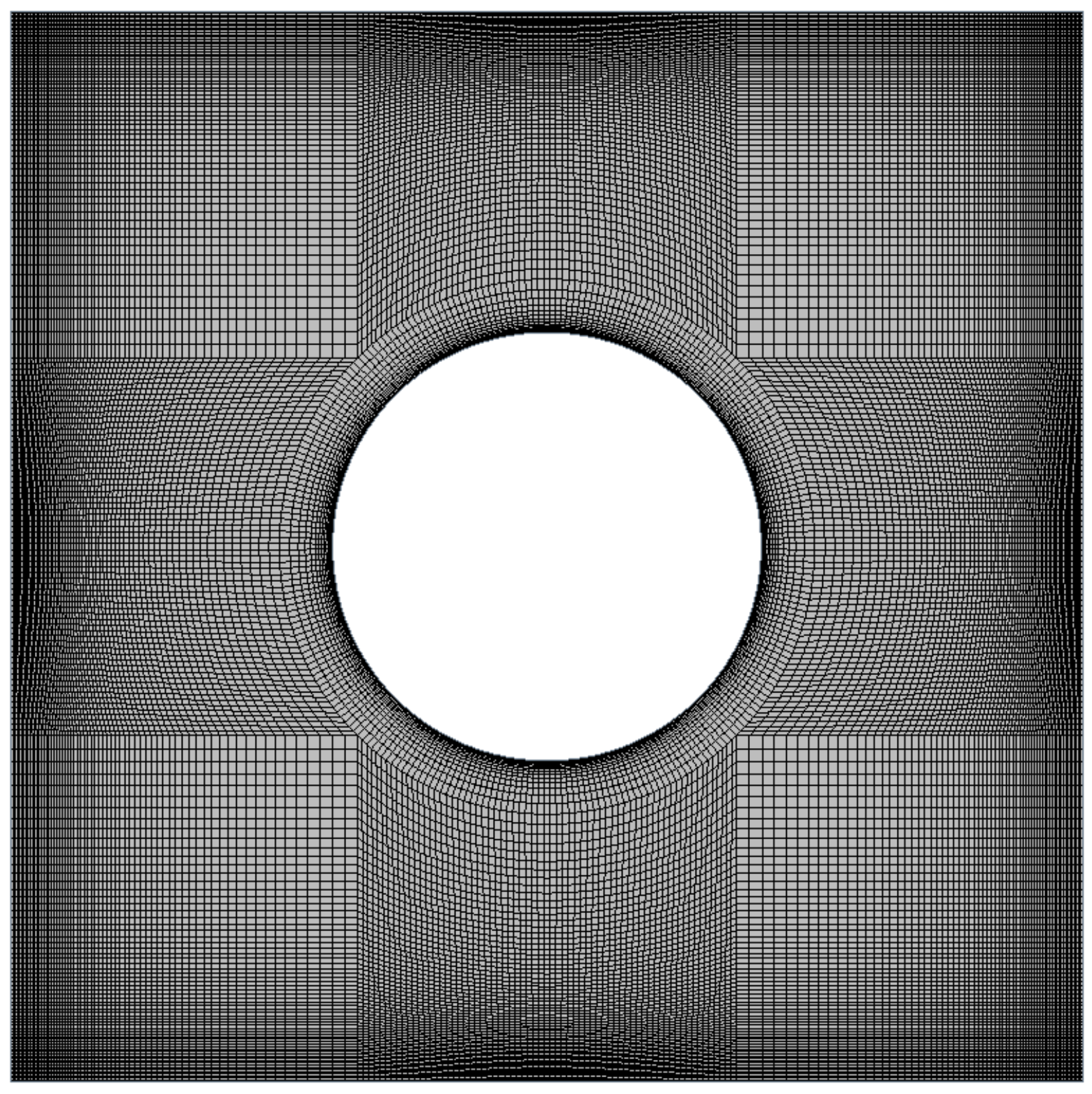
2. Numerical Details
3. Results and Discussion
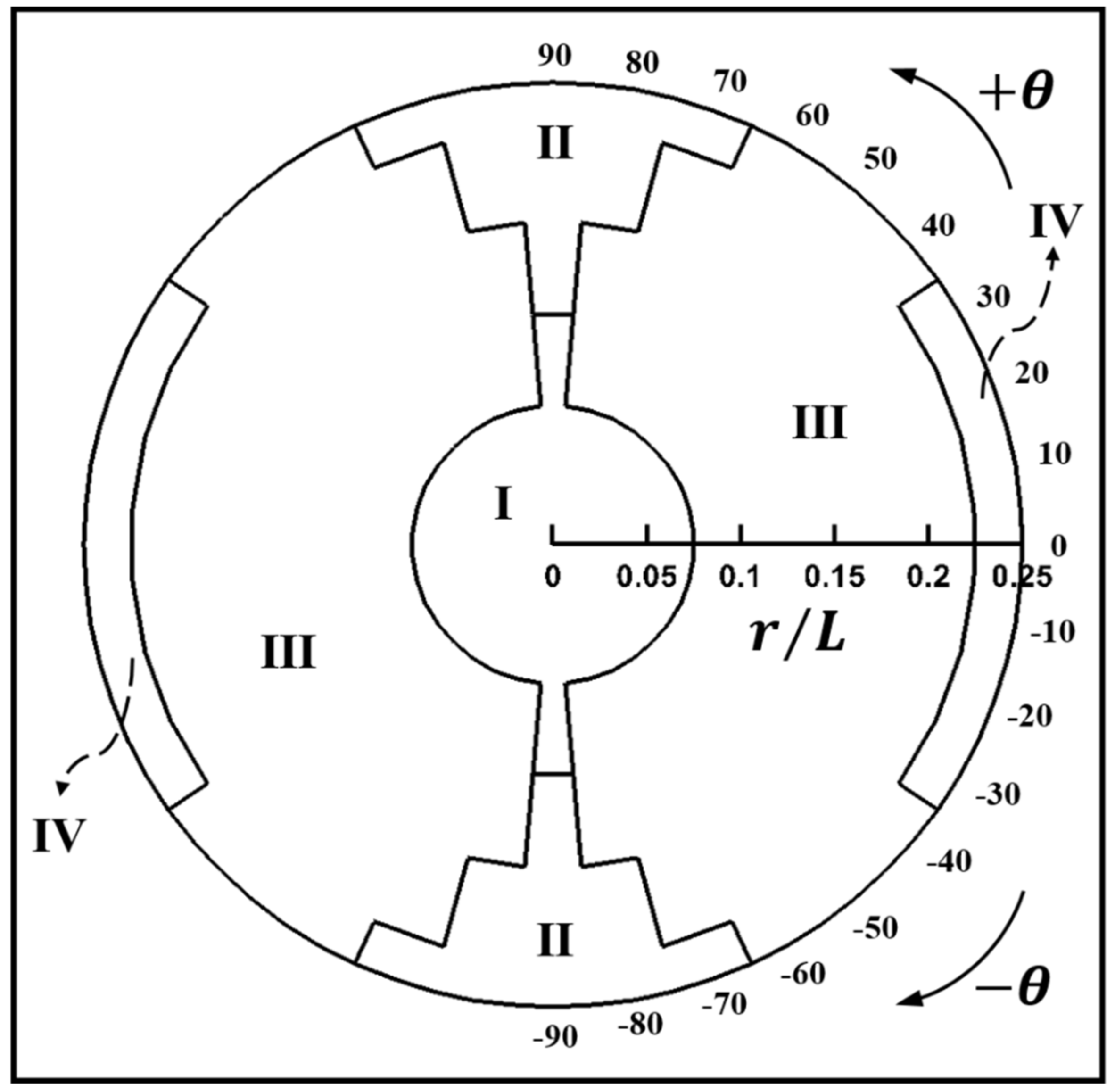
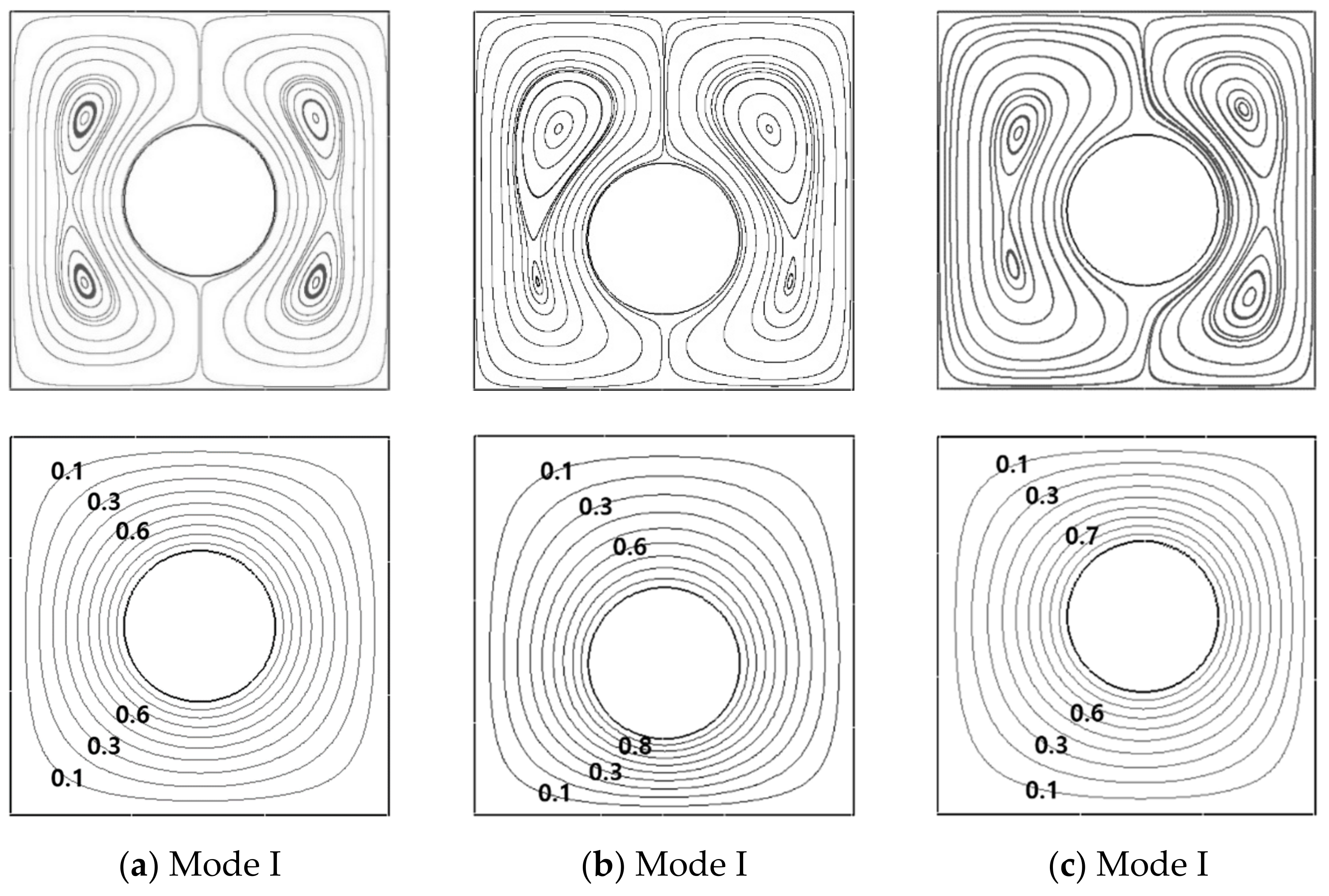
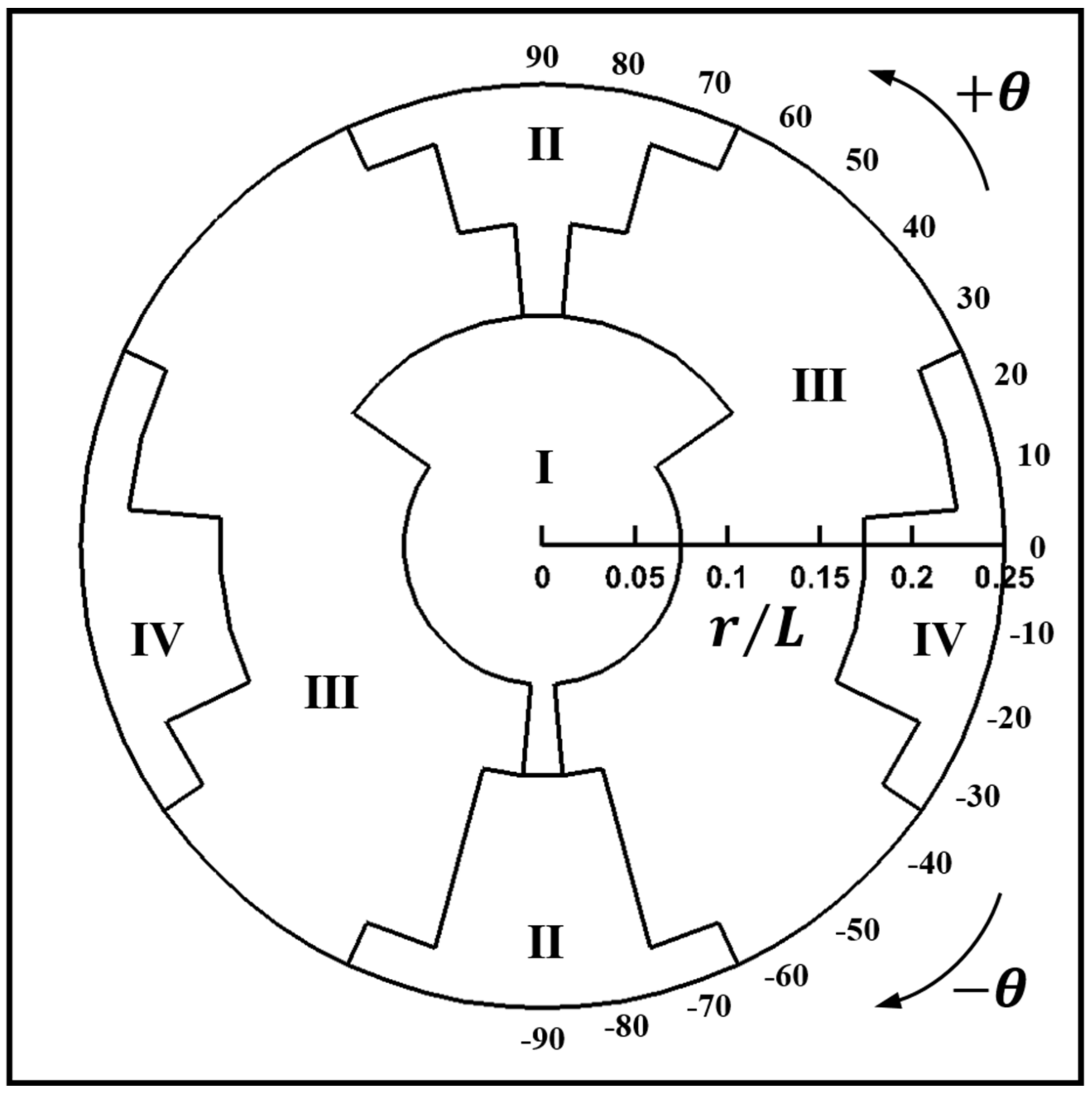
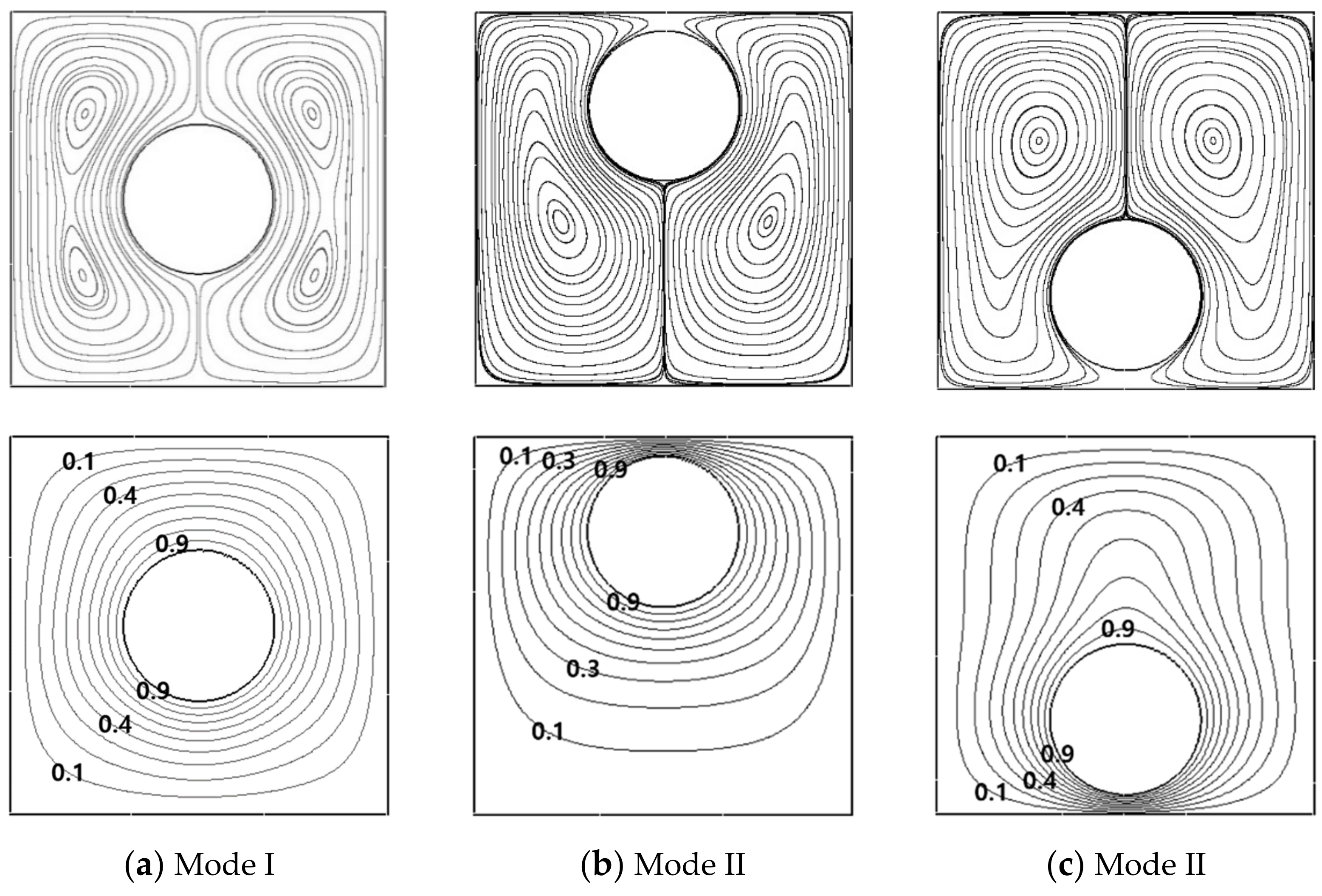
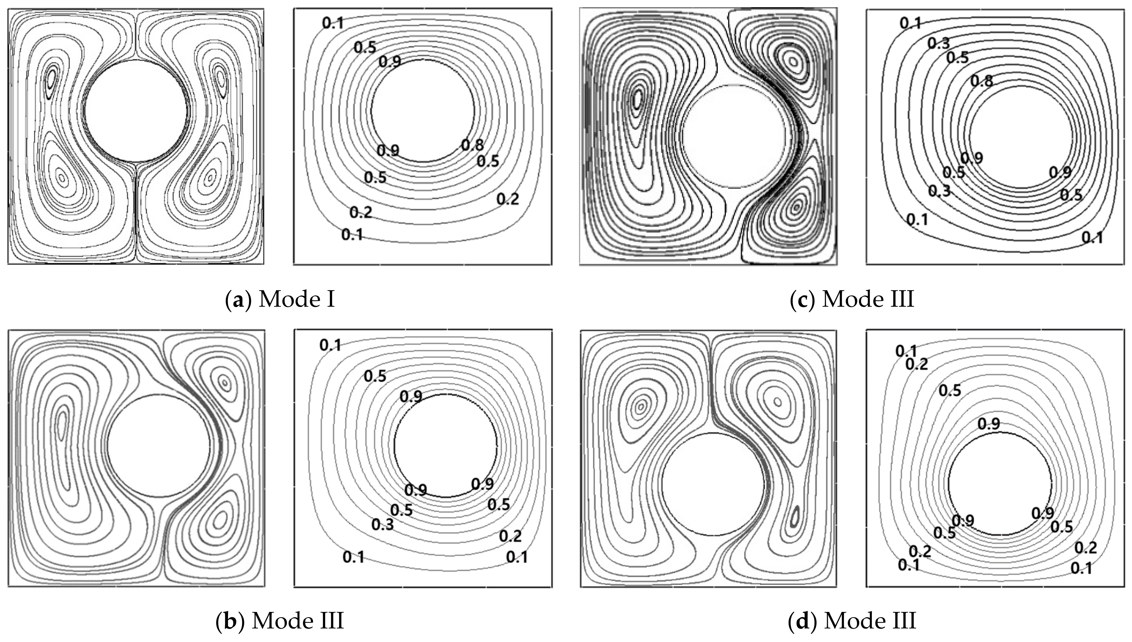
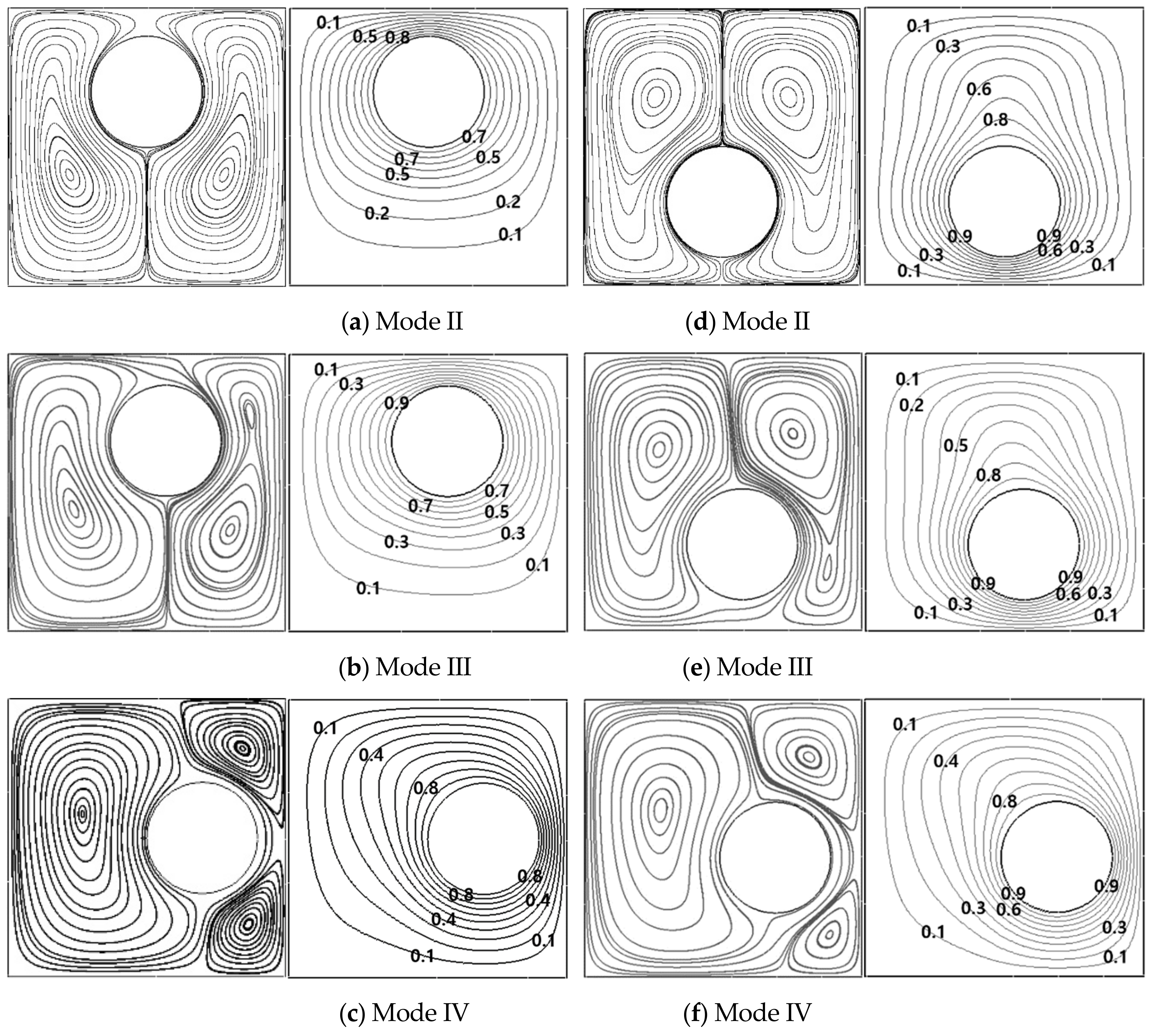
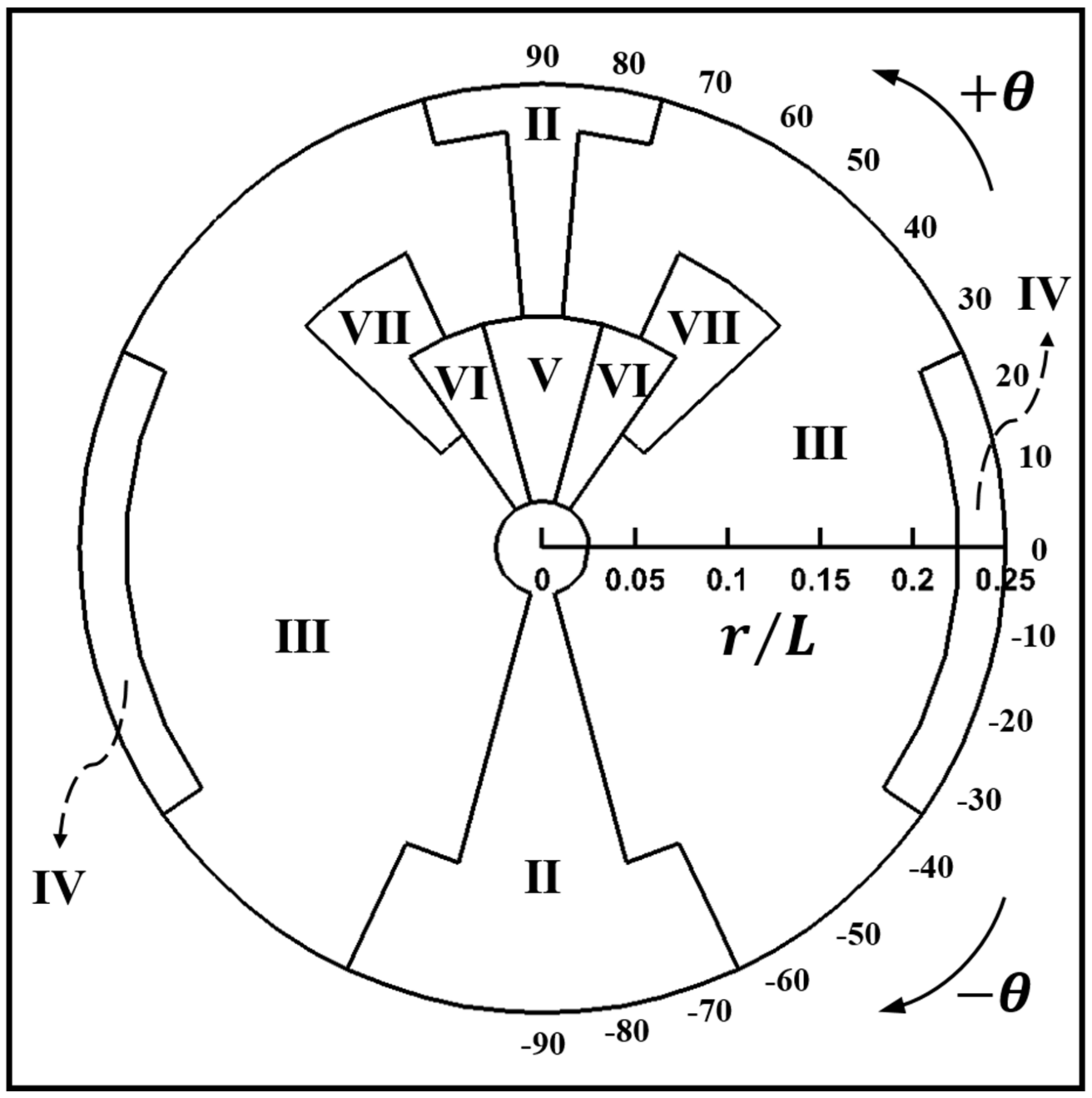
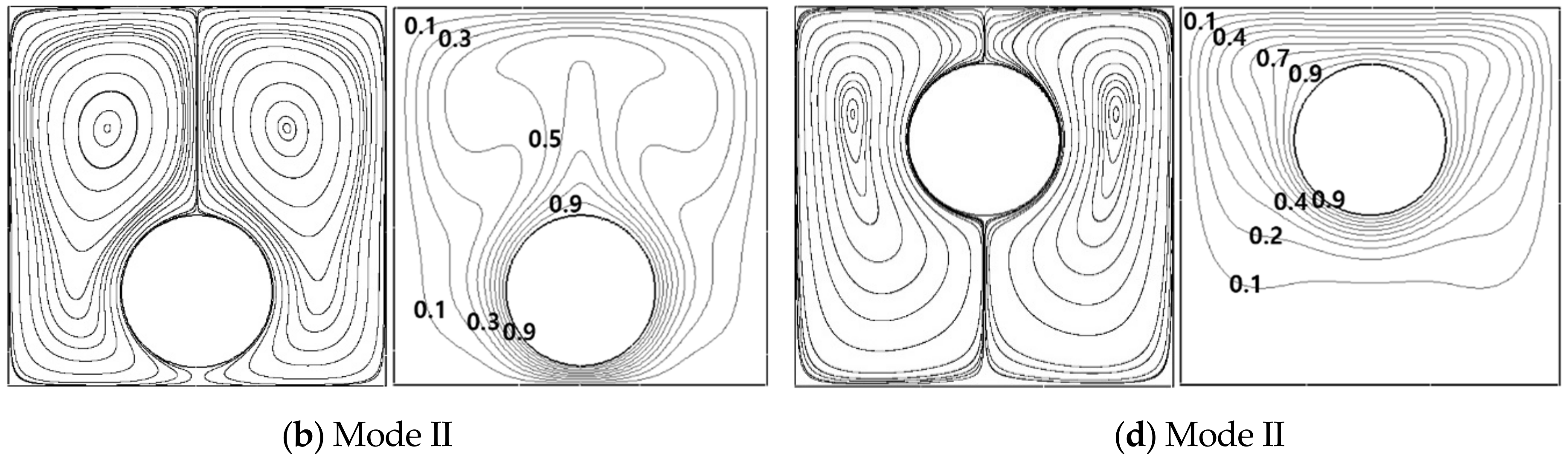
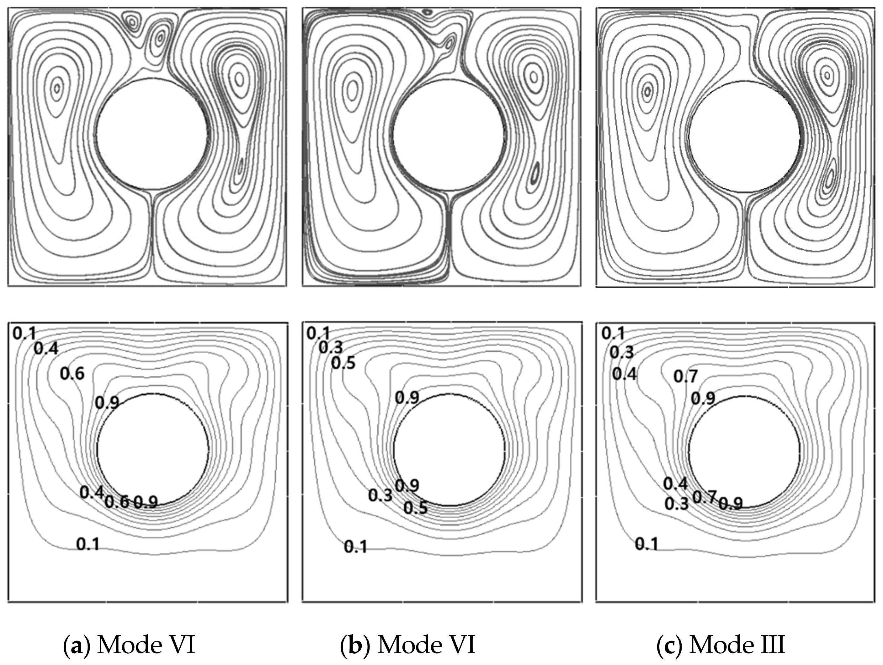
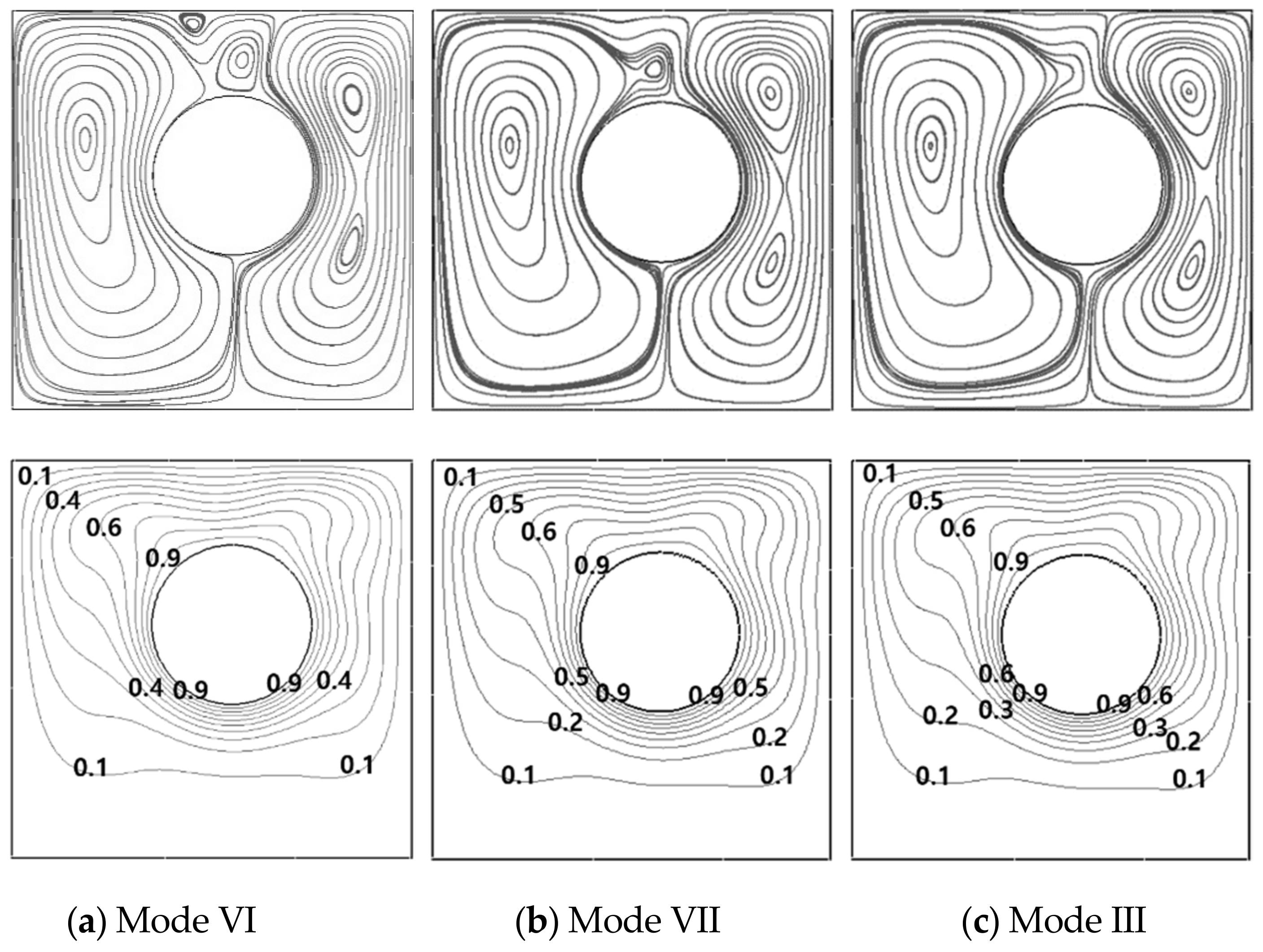
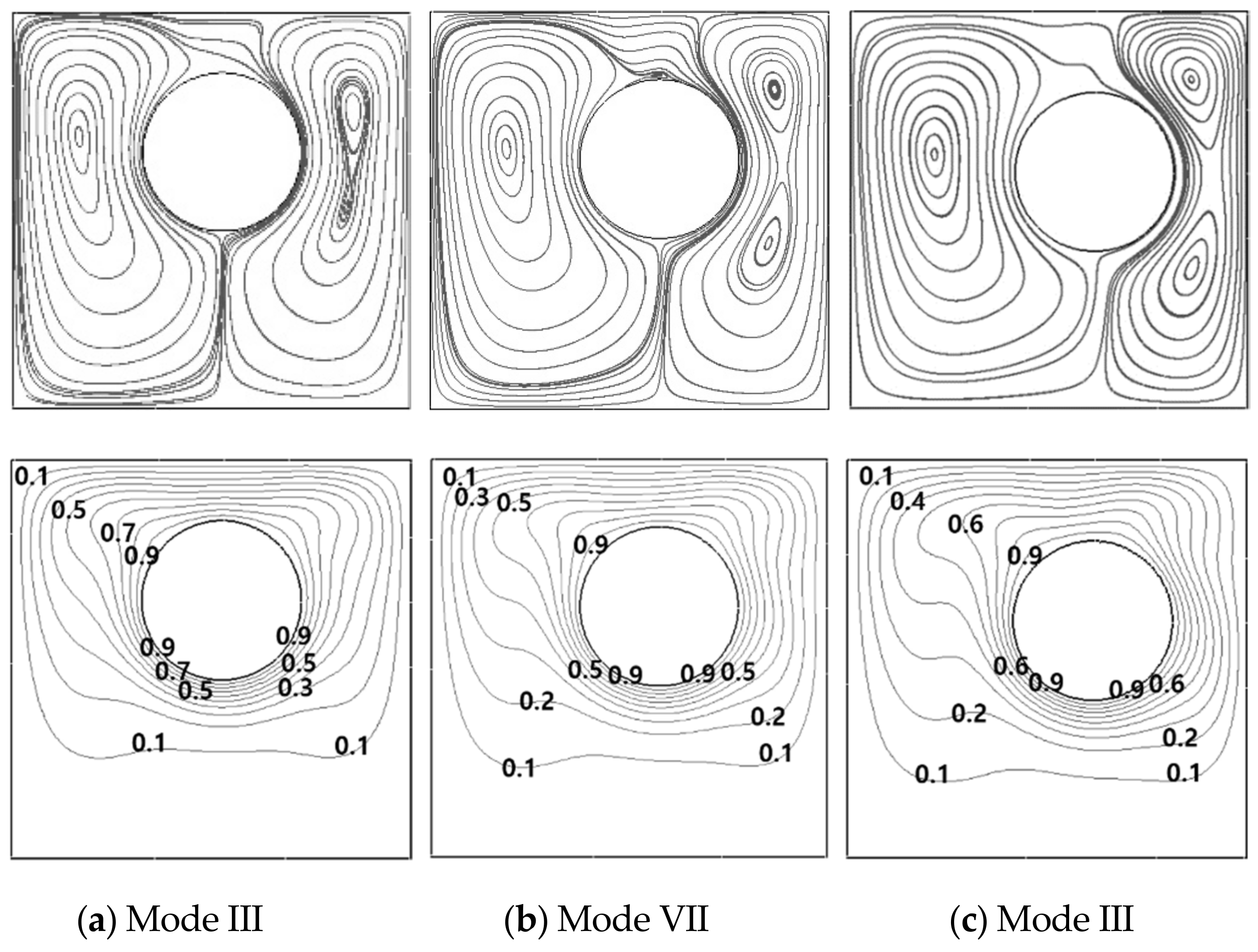
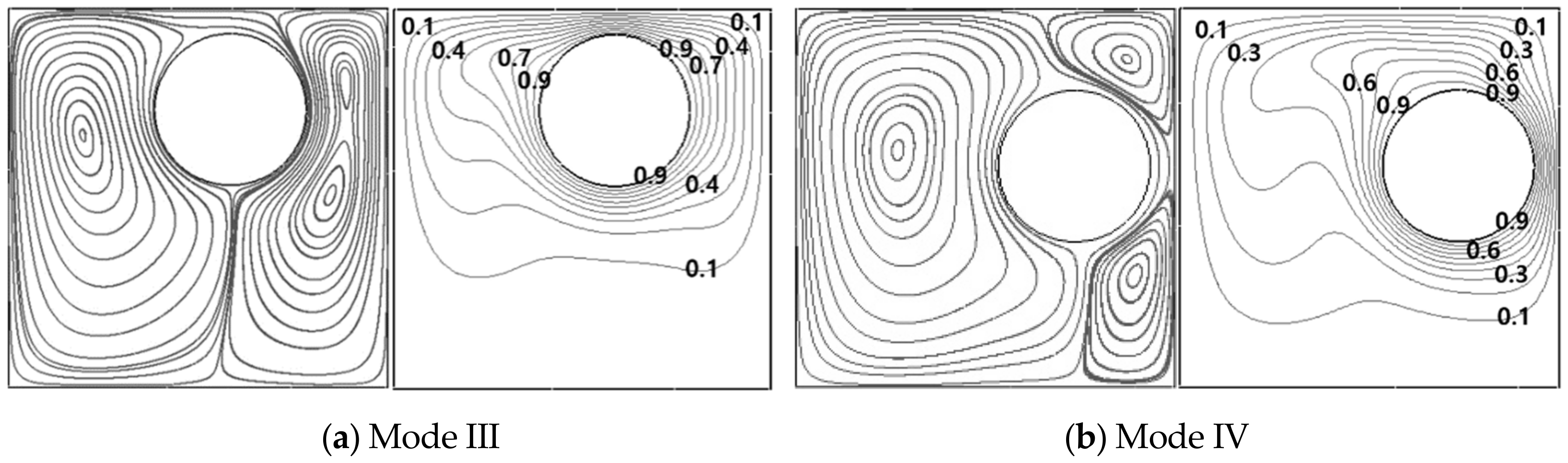
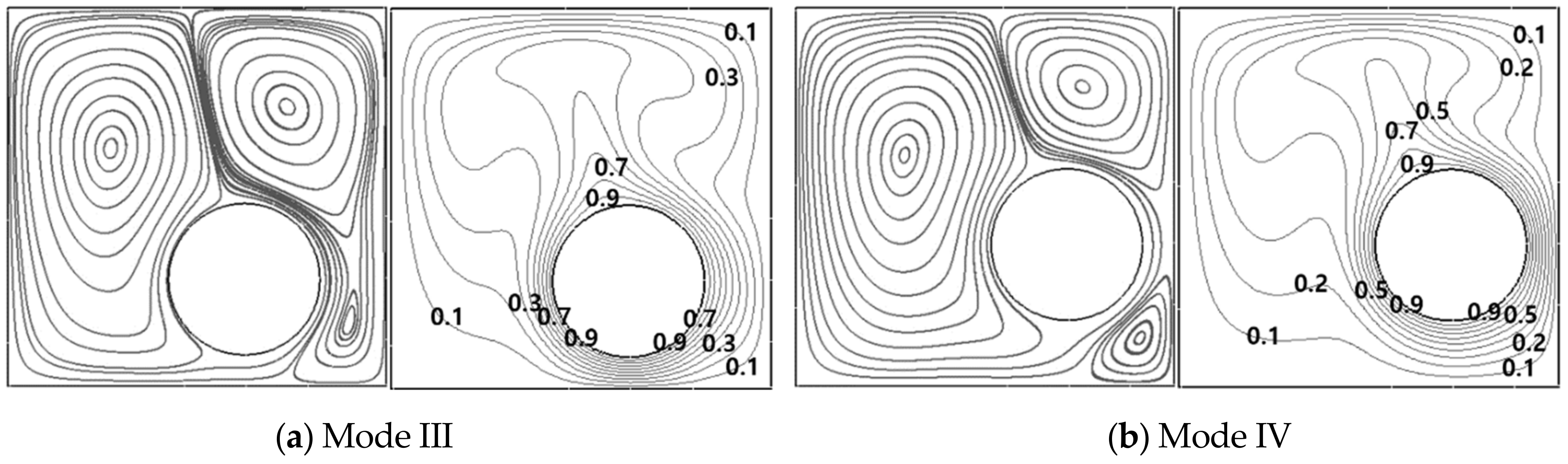
3.1. Map and Patterns of Flow and Thermal Fields
3.1.1. Ra = 103
3.1.2. Ra = 104
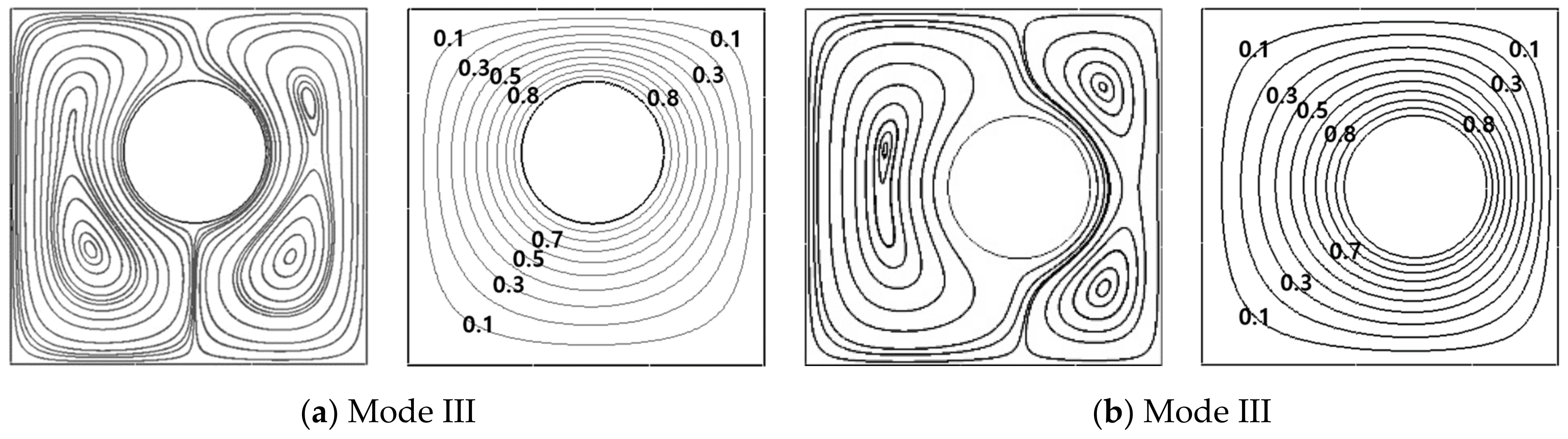
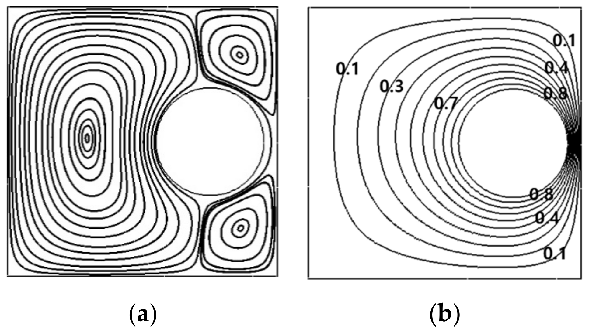
3.1.3. Ra = 105
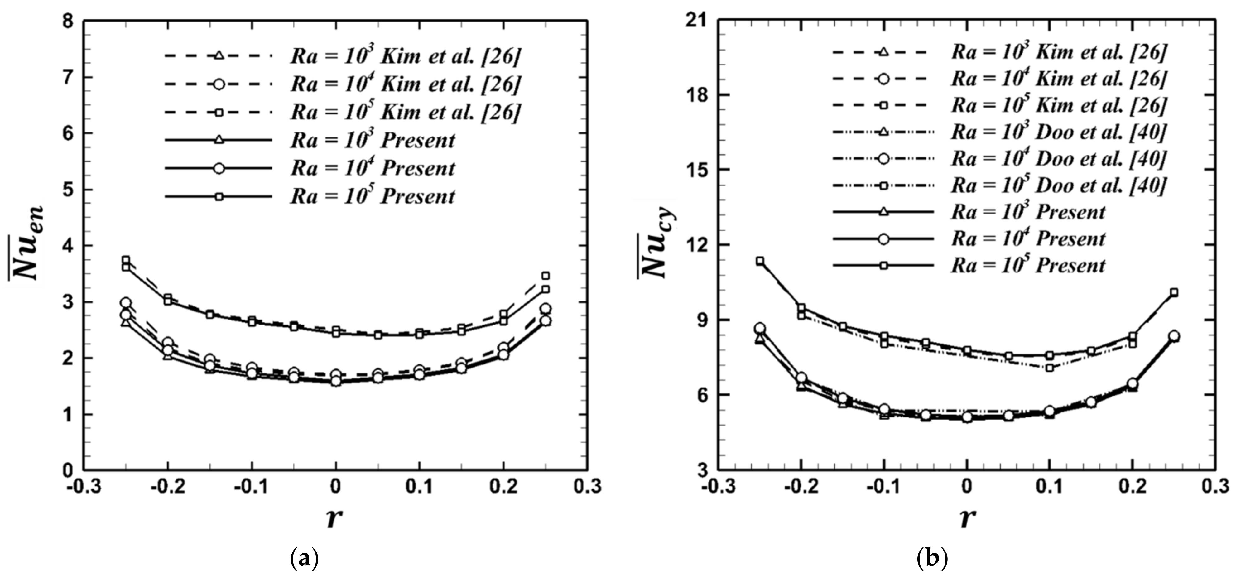
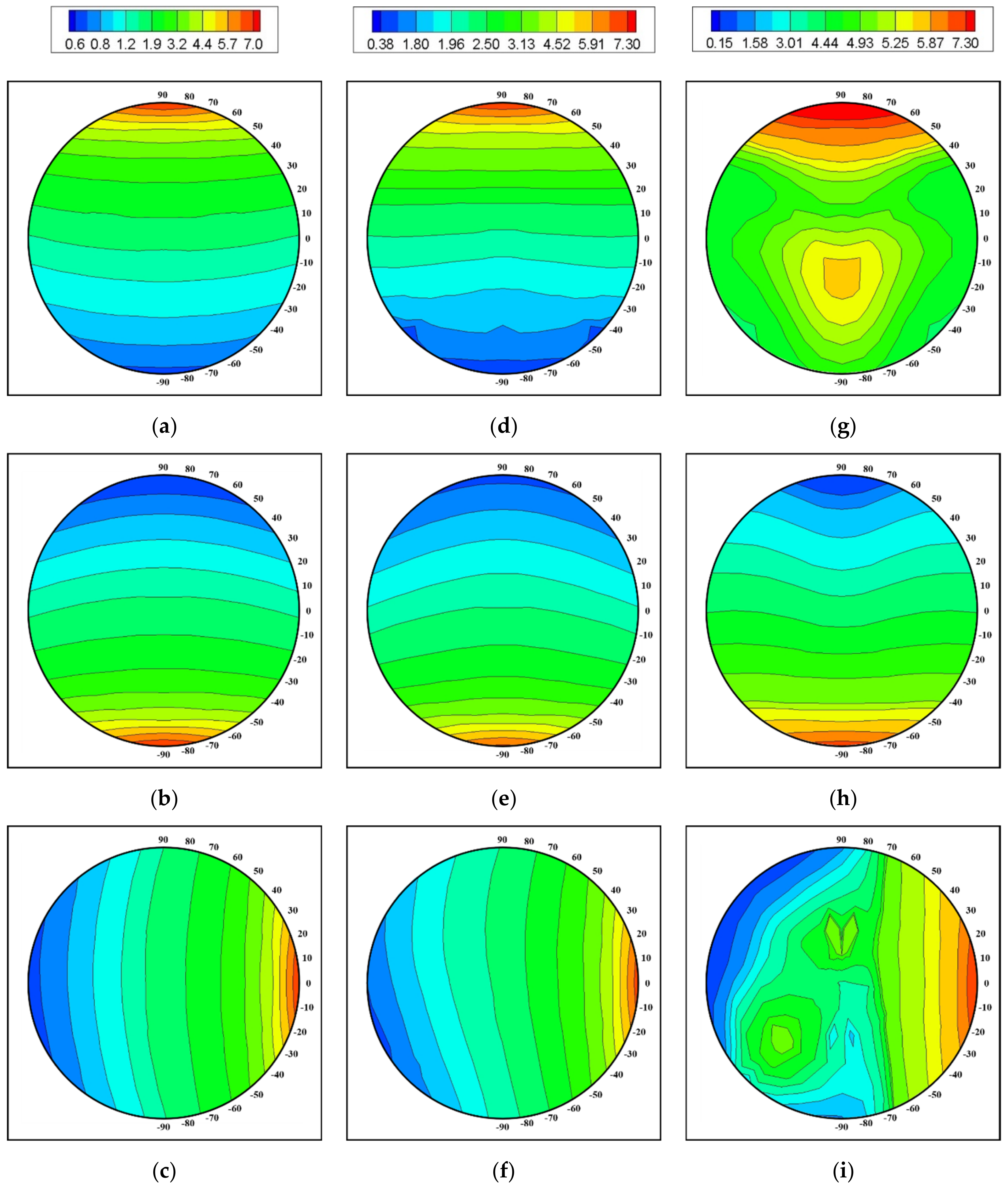
3.2. Nusselt Number
4. Conclusions
Author Contributions
Funding
Institutional Review Board Statement
Informed Consent Statement
Data Availability Statement
Acknowledgments
Conflicts of Interest
References
- Ghaddar, N.K. Natural convection heat transfer between a uniformly heated cylindrical element and its rectangular enclosure. Int. J. Heat Mass Transf. 1992, 35, 2327–2334. [Google Scholar] [CrossRef]
- Lee, S.H.; Seo, Y.M.; Yoon, H.S.; Ha, M.Y. Three-dimensional natural convection around an inner circular cylinder located in a cubic enclosure with sinusoidal thermal boundary condition. Int. J. Heat Mass Transf. 2016, 101, 807–823. [Google Scholar] [CrossRef]
- Bhowmick, D.; Randive, P.R.; Pati, S.; Agrawal, H.; Kumar, A.; Kumar, P. Natural convection heat transfer and entropy generation from a heated cylinder of different geometry in an enclosure with non-uniform temperature distribution on the walls. J. Therm. Anal. Calorim. 2020, 141, 839–857. [Google Scholar] [CrossRef]
- Park, J.; Kim, M.; Mun, G.S.; Park, Y.G.; Ha, M.Y. Natural convection in a square enclosure with a circular cylinder with adiabatic side walls according to bottom wall temperature variation. J. Mech. Sci. Technol. 2018, 32, 3201–3211. [Google Scholar] [CrossRef]
- Roslan, R.; Saleh, H.; Hashim, I.; Bataineh, A.S. Natural convection in an enclosure containing a sinusoidally heated cylindrical source. Int. J. Heat Mass Transf. 2014, 70, 119–127. [Google Scholar] [CrossRef] [Green Version]
- Dash, S.M.; Lee, T.S. Natural convection from inclined square cylinder using novel flexible forcing IB-LBM approach. Eng. Appl. Comput. Fluid Mech. 2014, 8, 91–103. [Google Scholar] [CrossRef] [Green Version]
- Jelita, M.; Mudia, H.; Afriani, S.; Kasim, U.I.S.S. Analysis of fluid dynamics and heat transfer inside an elliptical cylinder in a square enclosure. Adv. Theor. Appl. Mech. 2017, 10, 11–20. [Google Scholar] [CrossRef]
- Cho, H.W.; Park, Y.G.; Ha, M.Y. The natural convection in a square enclosure with two hot inner cylinders Part I: The effect of one elliptical cylinder with various aspect ratios in a vertical array. Int. J. Heat Mass Transf. 2018, 125, 815–827. [Google Scholar] [CrossRef]
- Raman, S.K.; Prakash, K.A.; Vengadesan, S. Natural convection from a heated elliptic cylinder with a different axis ratio in a square enclosure. Numer. Heat Transf. Part A Appl. 2012, 62, 639–658. [Google Scholar] [CrossRef]
- Souayeh, B.; Ben-Cheikh, N.; Ben-Beya, B. Numerical simulation of three-dimensional natural convection in a cubic enclosure induced by an isothermally-heated circular cylinder at different inclinations. Int. J. Therm. Sci. 2016, 110, 325–339. [Google Scholar] [CrossRef]
- Seo, Y.M.; Doo, J.H.; Ha, M.Y. Three-dimensional flow instability of natural convection induced by variation in radius of inner circular cylinder inside cubic enclosure. Int. J. Heat Mass Transf. 2016, 95, 566–578. [Google Scholar] [CrossRef] [Green Version]
- Yoon, H.S.; Yu, D.H.; Ha, M.Y.; Park, Y.G. Three-dimensional natural convection in an enclosure with a sphere at different vertical locations. Int. J. Heat Mass Transf. 2016, 53, 3143–3155. [Google Scholar] [CrossRef]
- Lu, J.; Shi, B.; Guo, Z.; Chai, Z. Numerical study on natural convection in a square enclosure containing a rectangular heated cylinder. Front. Energy Power Eng. China 2009, 3, 373. [Google Scholar] [CrossRef]
- Moukalled, F.; Diab, H.; Acharya, S. Laminar natural convection in a horizontal rhombic annulus. Numer. Heat Transf. Part A Appl. 1993, 24, 89–107. [Google Scholar] [CrossRef]
- Moukalled, F.; Acharya, S. Natural convection in the annulus between concentric horizontal circular and square cylinders. J. Thermophys. Heat Trans. 1996, 10, 524–531. [Google Scholar] [CrossRef]
- Yoon, H.S.; Jung, J.H.; Park, Y.G. Natural convection in a square enclosure with two horizontal cylinders. Numer. Heat Transf. Part A Appl. 2012, 62, 701–721. [Google Scholar] [CrossRef]
- Yoon, H.S.; Park, Y.G.; Jung, J.H. Natural convection in a square enclosure with differentially heated two horizontal cylinders. Numer. Heat Transf. Part A Appl. 2014, 65, 302–326. [Google Scholar] [CrossRef]
- Park, H.K.; Ha, M.Y.; Yoon, H.S.; Park, Y.G.; Son, C. A numerical study on natural convection in an inclined square enclosure with a circular cylinder. Int. J. Heat Mass Transf. 2013, 66, 295–314. [Google Scholar] [CrossRef]
- Shu, C.; Zhu, Y.D. Efficient computation of natural convection in a concentric annulus between an outer square cylinder and an inner circular cylinder. Int. J. Numer. Methods Fluids 2002, 38, 429–445. [Google Scholar] [CrossRef]
- Angeli, D.; Levoni, P.; Barozzi, G.S. Numerical predictions for stable buoyant regimes within a square cavity containing a heated horizontal cylinder. Int. J. Heat Mass Transf. 2008, 51, 553–565. [Google Scholar] [CrossRef]
- Seo, Y.M.; Ha, M.Y.; Park, Y.G. The effect of four elliptical cylinders with different aspect ratios on the natural convection inside a square enclosure. Int. J. Heat Mass Transf. 2018, 122, 491–503. [Google Scholar] [CrossRef]
- Zhang, P.; Zhang, X.; Deng, J.; Song, L. A numerical study of natural convection in an inclined square enclosure with an elliptic cylinder using variational multiscale element free Galerkin method. Int. J. Heat Mass Transf. 2016, 99, 721–737. [Google Scholar] [CrossRef]
- Park, Y.G.; Ha, M.Y.; Choi, C.; Park, J. Natural convection in a square enclosure with two inner circular cylinders positioned at different vertical locations. Int. J. Heat Mass Transf. 2014, 77, 501–518. [Google Scholar] [CrossRef]
- Dash, S.M.; Lee, T.S. Natural convection in a square enclosure with a square heat source at different horizontal and diagonal eccentricities. Numer. Heat Transf. Part A Appl. 2015, 68, 686–710. [Google Scholar] [CrossRef]
- Shu, C.; Xue, H.; Zhu, Y.D. Numerical study of natural convection in an eccentric annulus between a square outer cylinder and a circular inner cylinder using DQ method. Int. J. Heat Mass Transf. 2001, 44, 3321–3333. [Google Scholar] [CrossRef]
- Kim, B.S.; Lee, D.S.; Ha, M.Y.; Yoon, H.S. A numerical study of natural convection in a square enclosure with a circular cylinder at different vertical locations. Int. J. Heat Mass Transf. 2008, 51, 1888–1906. [Google Scholar] [CrossRef]
- Yoon, H.S.; Ha, M.Y.; Kim, B.S.; Yu, D.H. Effect of the position of a circular cylinder in a square enclosure on natural convection at Rayleigh number of 107. Phys. Fluids 2009, 21, 047101. [Google Scholar] [CrossRef]
- Hussain, S.H.; Hussein, A.K. Numerical investigation of natural convection phenomena in a uniformly heated circular cylinder immersed in square enclosure filled with air at different vertical locations. Int. Commun. Heat Mass Transf. 2010, 37, 1115–1126. [Google Scholar] [CrossRef]
- Park, Y.G.; Yoon, H.S.; Ha, M.Y. Natural convection in square enclosure with hot and cold cylinders at different vertical locations. Int. J. Heat Mass Transf. 2012, 55, 7911–7925. [Google Scholar] [CrossRef]
- Park, Y.G.; Ha, M.Y.; Yoon, H.S. Study on natural convection in a cold square enclosure with a pair of hot horizontal cylinders positioned at different vertical locations. Int. J. Heat Mass Transf. 2013, 65, 696–712. [Google Scholar] [CrossRef]
- Baranwal, A.K.; Chhabra, R. Effect of Prandtl number on free convection from two cylinders in a square enclosure. Heat Transf. Eng. 2016, 37, 545–556. [Google Scholar] [CrossRef]
- Park, Y.G.; Ha, M.Y.; Park, J. Natural convection in a square enclosure with four circular cylinders positioned at different rectangular locations. Int. J. Heat Mass Transf. 2015, 81, 490–511. [Google Scholar] [CrossRef]
- Seo, Y.M.; Park, Y.G.; Kim, M.; Yoon, H.S.; Ha, M.Y. Two-dimensional flow instability induced by natural convection in a square enclosure with four inner cylinders. Part I: Effect of horizontal position of inner cylinders. Int. J. Heat Mass Transf. 2017, 113, 1306–1318. [Google Scholar] [CrossRef]
- Seo, Y.M.; Mun, G.S.; Park, Y.G.; Ha, M.Y. Two-dimensional flow instability induced by natural convection in a square enclosure with four inner cylinders. Part II: Effect of various positions of inner cylinders. Int. J. Heat Mass Transf. 2017, 113, 1319–1331. [Google Scholar] [CrossRef]
- Bararnia, H.; Soleimani, S.; Ganji, D.D. Lattice Boltzmann simulation of natural convection around a horizontal elliptic cylinder inside a square enclosure. Int. Commun. Heat Mass Transf. 2011, 38, 1436–1442. [Google Scholar] [CrossRef]
- Lee, J.M.; Ha, M.Y.; Yoon, H.S. Natural convection in a square enclosure with a circular cylinder at different horizontal and diagonal locations. Int. J. Heat Mass Transf. 2010, 53, 5905–5919. [Google Scholar] [CrossRef]
- Kang, D.H.; Ha, M.Y.; Yoon, H.S.; Choi, C. Bifurcation to unsteady natural convection in square enclosure with a circular cylinder at Rayleigh number of 107. Int. J. Heat Mass Transf. 2013, 64, 926–944. [Google Scholar] [CrossRef]
- Spizzichino, A.; Zemach, E.; Feldman, Y. Oscillatory instability of a 3D natural convection flow around a tandem of cold and hot vertically aligned cylinders placed inside a cold cubic enclosure. Int. J. Heat Mass Transf. 2019, 141, 327–345. [Google Scholar] [CrossRef]
- Cho, H.W.; Seo, Y.M.; Mun, G.S.; Ha, M.Y.; Park, Y.G. The effect of instability flow for two-dimensional natural convection in a square enclosure with different arrays of two inner cylinders. Int. J. Heat Mass Transf. 2017, 114, 307–317. [Google Scholar] [CrossRef]
- Doo, J.H.; Mun, G.S.; Ha, M.Y.; Seong, S.Y. Thermo-dynamic irreversibility induced by natural convection in square enclosure with inner cylinder. Part-II: Effect of vertical position of inner cylinder. Int. J. Heat Mass Transf. 2016, 97, 1120–1139. [Google Scholar] [CrossRef]
- Liao, C.C.; Lin, C.A. Transitions of natural convection flows in a square enclosure with a heated circular cylinder. Appl. Therm. Eng. 2014, 72, 41–47. [Google Scholar] [CrossRef]
- Pandey, S.; Park, Y.G.; Ha, M.Y. An exhaustive review of studies on natural convection in enclosures with and without internal bodies of various shapes. Int. J. Heat Mass Transf. 2019, 138, 762–795. [Google Scholar] [CrossRef]
- Aghaei, A.; Sheikhzadeh, G.A.; Goodarzi, M.; Hasani, H.; Damirchi, H.; Afrand, M. Effect of horizontal and vertical elliptic baffles inside an enclosure on the mixed convection of a MWCNTs-water nanofluid and its entropy generation. Eur. Phys. J. Plus 2018, 133, 486. [Google Scholar] [CrossRef]
- Goodarzi, M.; D’Orazio, A.; Keshavarzi, A.; Mousavi, S.; Karimipour, A. Develop the nano scale method of lattice Boltzmann to predict the fluid flow and heat transfer of air in the inclined lid driven cavity with a large heat source inside, Two case studies: Pure natural convection & mixed convection. Phys. A Stat. Mech. Appl. 2018, 509, 210–233. [Google Scholar]
- Pordanjani, A.H.; Aghakhani, S.; Karimipour, A.; Afrand, M.; Goodarzi, M. Investigation of free convection heat transfer and entropy generation of nanofluid flow inside a cavity affected by magnetic field and thermal radiation. J. Therm. Anal. Calorim. 2019, 137, 997–1019. [Google Scholar] [CrossRef]
- Yousefzadeh, S.; Rajabi, H.; Ghajari, N.; Sarafraz, M.M.; Akbari, O.A.; Goodarzi, M. Numerical investigation of mixed convection heat transfer behavior of nanofluid in a cavity with different heat transfer areas. J. Therm. Anal. Calorim. 2019, 140, 2779–2803. [Google Scholar] [CrossRef]
- Rozati, S.A.; Montazerifar, F.; Ali Akbari, O.; Hoseinzadeh, S.; Nikkhah, V.; Marzban, A.; Abdolvand, H.; Goodarzi, M. Natural convection heat transfer of water/Ag nanofluid inside an elliptical enclosure with different attack angles. Math. Methods Appl. Sci. 2020, 1–18. [Google Scholar] [CrossRef]
- Kim, J.; Moin, P. Application of a fractional-step method to incompressible Navier-Stokes equations. J. Comput. Phys. 1985, 59, 308–323. [Google Scholar] [CrossRef]
- Zang, Y.; Street, R.L.; Koseff, J.R. A non-staggered grid, fractional step method for time-dependent incompressible Navier-Stokes equations in curvilinear coordinates. J. Comput. Phys. 1994, 114, 18–33. [Google Scholar] [CrossRef]


| Ra | Present | Park et al. [18] | Kim et al. [26] | Lee et al. [36] | |||
|---|---|---|---|---|---|---|---|
| Diff. (%) | Diff. (%) | Diff. (%) | |||||
| 103 | 5.041 | 5.024 | −0.346 | 5.093 | 1.024 | 5.107 | 1.285 |
| 104 | 5.132 | 5.129 | −0.064 | 5.108 | −0.473 | 5.109 | −0.456 |
| 105 | 7.816 | 7.817 | 0.010 | 7.767 | −0.630 | 7.761 | −0.712 |
Publisher’s Note: MDPI stays neutral with regard to jurisdictional claims in published maps and institutional affiliations. |
© 2021 by the authors. Licensee MDPI, Basel, Switzerland. This article is an open access article distributed under the terms and conditions of the Creative Commons Attribution (CC BY) license (https://creativecommons.org/licenses/by/4.0/).
Share and Cite
Yoon, H.-S.; Shim, Y.-J. Classification of Flow Modes for Natural Convection in a Square Enclosure with an Eccentric Circular Cylinder. Energies 2021, 14, 2788. https://doi.org/10.3390/en14102788
Yoon H-S, Shim Y-J. Classification of Flow Modes for Natural Convection in a Square Enclosure with an Eccentric Circular Cylinder. Energies. 2021; 14(10):2788. https://doi.org/10.3390/en14102788
Chicago/Turabian StyleYoon, Hyun-Sik, and Yoo-Jeong Shim. 2021. "Classification of Flow Modes for Natural Convection in a Square Enclosure with an Eccentric Circular Cylinder" Energies 14, no. 10: 2788. https://doi.org/10.3390/en14102788