Review

Technical Solutions of Forest Machine Hybridization

1
Department of Engineering, Faculty of Forestry and Wood Technology, Mendel University in Brno, 613 00 Brno, Czech Republic
2
Department of Forest Engineering, Faculty of Forestry and Wood Technology, University of Zagreb, Svetošimunska Cesta 23, 10000 Zagreb, Croatia
*
Author to whom correspondence should be addressed.
Energies 2021, 14(10), 2793; https://doi.org/10.3390/en14102793
Submission received: 25 March 2021 / Revised: 6 May 2021 / Accepted: 10 May 2021 / Published: 13 May 2021

Abstract

:
The paper deals with the characteristics of three different types of power train hybridization of forest logging machines and with the benefits of reducing environmental impacts by comparing new technology with more conventional, older technology. New hybridization options that could be implemented in forestry machines are also discussed. The paper divides a hybrid solution into three classes based on the energy used in the system of hybridization. First is an electro-hybrid system that uses an electric motor and battery or different storage device. The second, a hydraulic hybrid system, is a solution with a hydraulic accumulator, hydraulic motor, and pump. The third system is a combination of the electro-hybrid and hydraulic-hybrid system. The current technical and technological development of hybrid drive systems, as well as their components, has led to significant improvements in drive performance and thus better performance of the new generation of forest vehicles. Improved energy efficiency using hybrid propulsion systems in forest vehicles would result in a significant reduction in greenhouse gas emissions and possibly lower maintenance costs.

1. Introduction

Global climate change is currently taking place, and the change is associated with strong weather fluctuations, which result in calamities, whether of biotic or abiotic origin. During these calamities, there is a glut of wood in the market, and thus its price falls. The falling price requires a reduction in the costs associated with its harvesting. Deployment of hybrid machines can present a solution for this issue and hybrid machines have lower fuel consumption, which contributes to the total costs by up to 82% [1,2]. The solution correlates with the global trend of reducing emission limits for working machines. The Stage V emission standard is currently valid in the EU.
Hybrid drives of forest machines (harvester, forwarder, and skidder) are based on solutions that come from the automotive industry. From the sector of machine hybridization, Sellgren [3] mentioned so-called “engine downsizing”, when engine sizes are scaled down and emissions are thus reduced. The most common hybrid drive design currently utilizes electricity with an aim to solve the issue of a lack of the required power of a smaller engine, for example in harvesters. Such hybridization is referred to in the literature as the electro-hybrid drive [4].
In addition to the type above, a design based on the use of the pressure energy of liquid can be found. The machines utilizing this type of hybridization are often referred to as hydraulic hybrids. These two types of hybridization can also be combined with each other, and are known as electro-hydraulic hybrids (Figure 1). The accumulator–hydraulic motor–generator energy regeneration system (AMGERS) mentioned by Lin and Wang (2012) [5] is evidence of a possible combination.

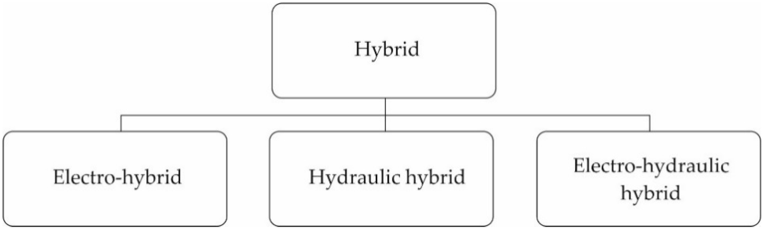
2. Concepts of Hybridization

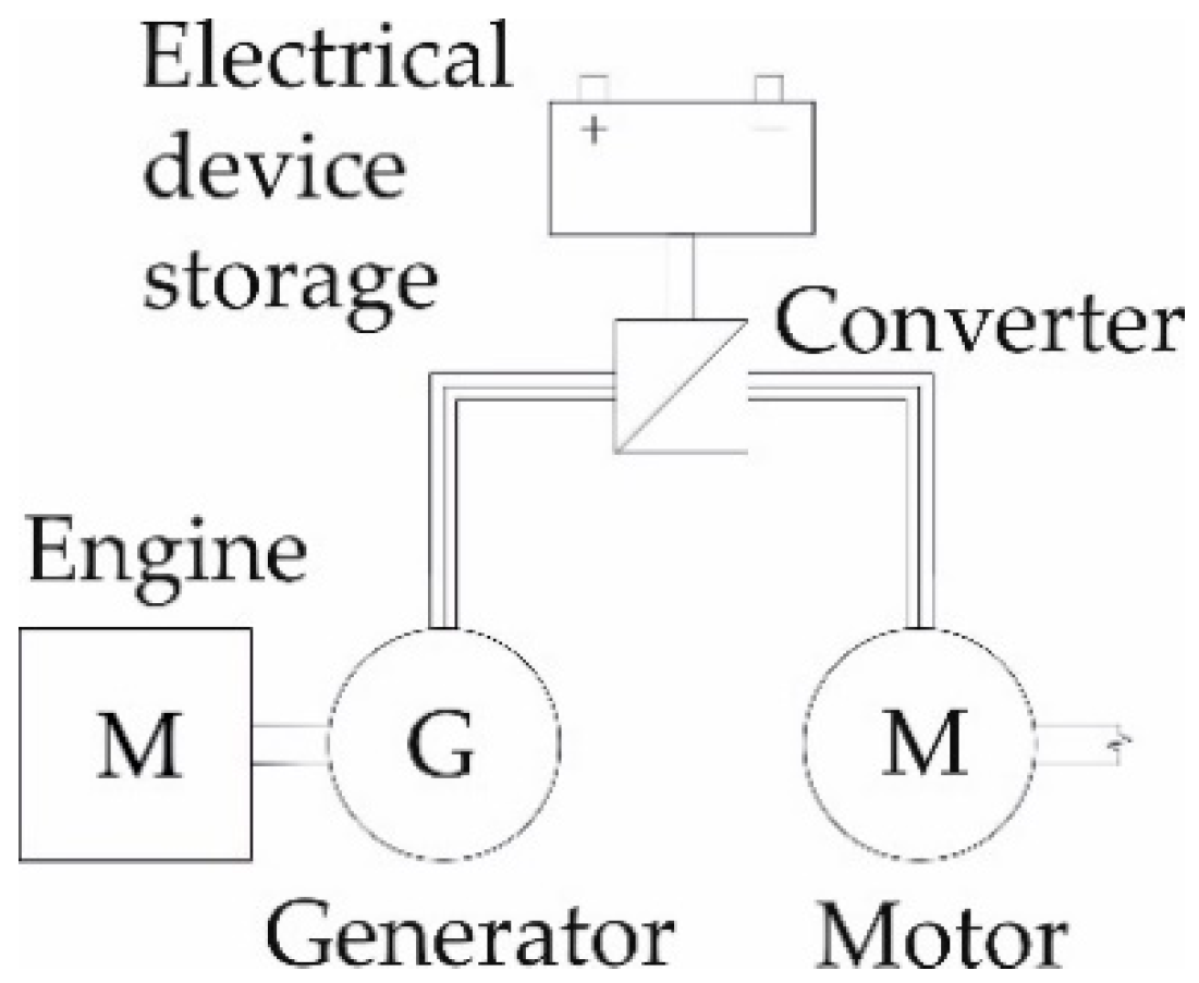
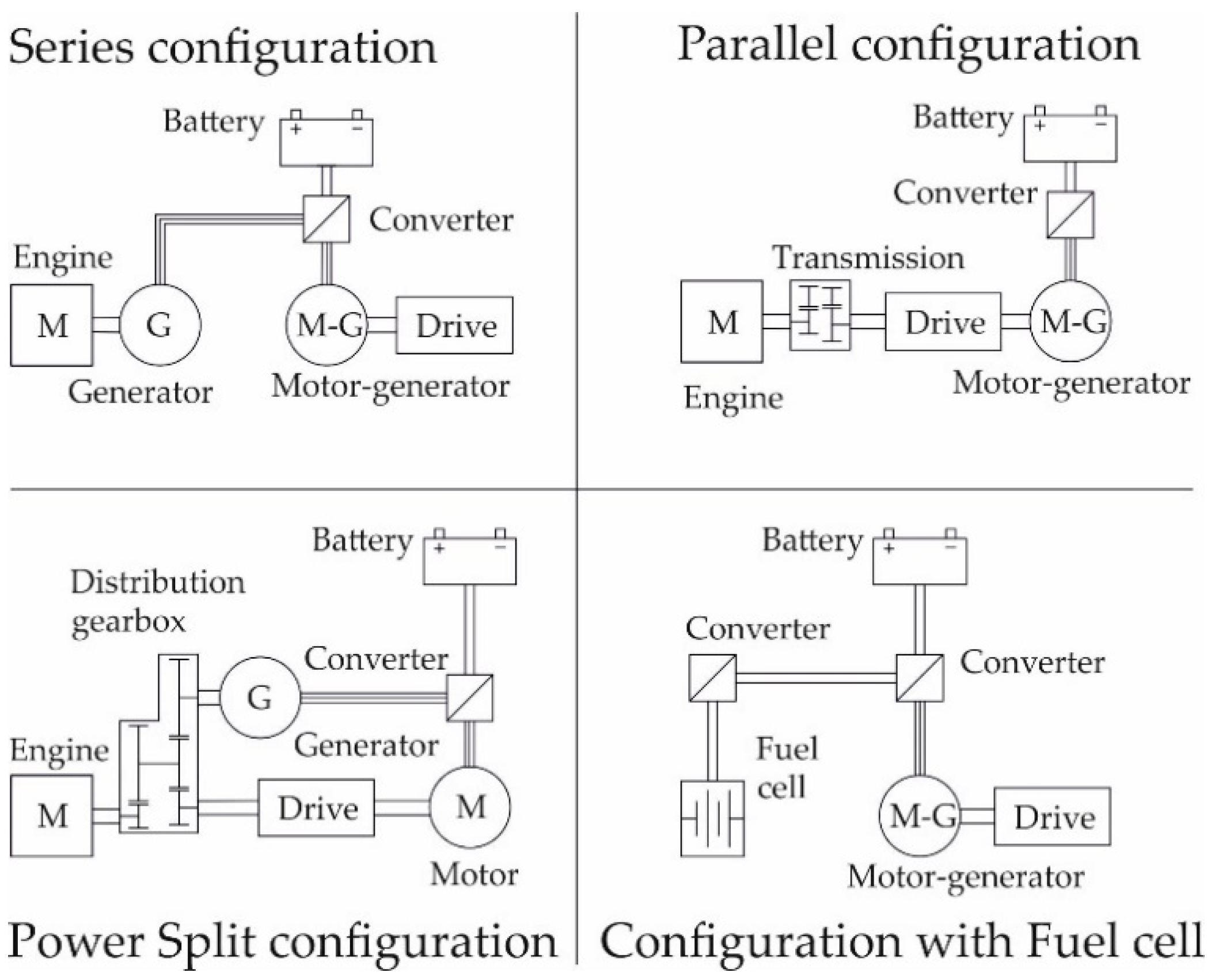
2.1. Electro-Hybrids

The electro-hybrid drive includes a generator, an inverter, an electrical storage device, and an electric motor (Figure 2). The generator generates electrical energy, which is led into the inverter, a type of static converter [6,7]. The static converter is a power electronic device without any moving parts, which converts parameters of electrical energy of one type (instantaneous value and time course of voltage and current, frequency, and number of phases) to other parameters of the required electrical energy of another type [7].
The inverter converts the input DC voltage to the output AC voltage [8]. Ishida and Higurashi [9] mentioned in their research the use of a DC converter which, as Kůs [8] stated, modifies the DC voltage and current parameters. Procházka et al. [10] showed the use of a static converter, which a DC converter and an inverter. The reason for using the word inverter instead of static converter is their identical names in the English language, but the difference in electrical engineering is quite obvious thanks to Kůs [8].
Batteries, capacitors, or supercapacitors can be considered electrical storage devices. Batteries must at first be charged with electrical energy, which is converted into chemical energy during charging [11]. When discharging, the opposite is true, i.e., chemical energy is converted into electrical energy. The capacitor is composed of two conductive (metal) electrodes, with the dielectric between them [12]. When charged, the capacitor interrupts the DC circuit due to a non-conductive dielectric [11]. The supercapacitor is a capacitor with larger physical dimensions and a higher capacity [13]. The supercapacitor has a higher energy density than the battery and a shorter charging (and discharging) time, in the order of seconds compared to the battery, where the charging time lasts several hours [14]. Some solutions combine these types of electrical storage devices [15]. The energy, stored in such a way, is led through the static converter into the electric motor, which converts electrical energy into mechanical energy [10]. The electric motor can even become, at the same time, a generator, i.e., recuperation [16]. The recuperating motor supplies active power to the network and takes reactive power from the network for magnetization [7].
Depending on the location of the electro-hybrid assembly in the drive system, the series configuration, parallel configuration, power split configuration, or series configuration with fuel cells (Figure 3) can be recognized. Due to the high consumption of logging machines, the series configuration with fuel cells cannot be used [16]. Therefore, parallel and series configurations are the most suitable for use in these machines.
The system from the manufacturer Logset Oy is the first available electro-hybrid harvester for the forestry market. It is a parallel hybrid configuration that utilizes an electric motor connected to the shaft of an internal combustion engine which is also the generator [17]. Switching of the electric motor between the motor and the generator mode is realized by the control unit. The control unit has the task of sensing the load of the internal combustion engine and, in case of any excessive load, starting the electric motor, thus relieving the load on the internal combustion engine [4]. When the engine load is below the normal limit, the electric motor acts as a generator, charging the supercapacitors [17]. The supercapacitors can be discharged and recharged within 9 to 10 s [4]. In comparison with the same conventional diesel harvester, the Logset hybrid system is 72% more powerful, with a 54% increase in torque, and hydraulic flow is increased by up to 27% [18].
Procházka et al. [10] also used a battery in their research of a hybrid harvester drive. The system uses a synchronous motor with permanent magnets which is able to work in generator mode [10]. Currently, a prototype hybrid harvester from Agama a.s. is being researched in cooperation with the Faculty of Forestry and Wood Technology of Mendel University in Brno. A similar system, however, not specified in detail, was created by the manufacturer Elforest Technologies AB, the product of which is known as “Elturbo”. The manufacturer, together with Pro Silva Qyj, created, for example, the hybrid harvester 910 EH, which included Elturbo. The battery was used to store the electric energy [19]. An interesting solution was created by the manufacturer Koller GmBH with the KX 800 E excavator yarder. The manufacturer again used an electric motor with a generator mode and connected them to the winches. In the case when an external force acted on the winches, recuperation took place. The energy obtained was stored in the supercapacitors [20]. The energy obtained was used again under high load conditions of the internal combustion engine of the machine, the same as the C860 hybrid wood chipper from Kesla Oyj. It is important to add that all the hybrid systems mentioned used parallel configurations.
The hybrid excavator system of Komatsu Ltd. is another interesting design with a combined arrangement (Figure 4). The system works with one supercapacitor and two electric motors, which are also generators [15]. The first electric motor is located between the internal combustion engine and the pump on the shaft. The electric motor primarily generates electricity and also relieves the internal combustion engine when it is overloaded. A second electric motor is used instead of a swinging hydraulic motor, while preserving the function. When braking, it recuperates which reduces, with respect to the properties of the supercapacitor, the possibility of electricity becoming unavailable in the electrical storage device [15]. A similar system has been created for an experimental excavator by CNH Industrial, known by its New Holland Agriculture brand, but with the use of a battery.
The system from Hitachi Ltd., utilizing a system similar to that of the excavator of Komatsu Ltd., is another hybrid solution that can be used in CTL technology. However, they have chosen the battery as their electrical storage device and added a generator for recharging the battery with respect to its charging time [15]. The generator is driven by a hydraulic motor which is located in the drilled branch (T) of the hydraulic circuit, which leads into the tank. The same design for generating electricity for recharging the electrical storage device is also used by the motor–generator energy regeneration system (MGERS). Lin and Wang [5] stated that a hydraulic motor without the possibility of flow control, which a generator is connected to, is mounted on the return branch of the hydraulic circuit. Electricity is led by the inverter (converter) into the storage device and then back to the electric motor, which is connected to the output shaft of the internal combustion engine upstream of the hydraulic motor. The system uses a supercapacitor as the electrical storage device [21].
A different method of electro-hybridization, which uses the same components by replacing one part of a conventional drive, is worth mentioning, in particular, replacement of the whole hydrostatic section and one part of the mechanical section of the hydrostatic–mechanical drive of the harvesters, forwarders, and excavators. A forwarder from the company Elforest Technologies AB, where each wheel is equipped with an electric motor, can serve as an example. Stoddart [22] stated that these are 30 kW AC electric motors. The generator connected to the distribution gearbox is the source of electricity. If the machine goes downhill, there is the possibility of recuperation. The battery was chosen as the electrical storage device. Thanks to the described design, the total weight of the machine was decreased [23]. The testing of the machine is finished but data are not available. Rong-Feng et al. [24] mentioned that electric motors can be fitted one by one to the bogie axle. Electric motors for wheel drive also use Agama a.s. technology in their hybrid trailers. An electric motor with the possibility of generator mode was placed in one wheel on each side. It was then connected to a converter and a lithium battery. Further, an electric motor driven by a hydraulic motor was connected to the converter. The solution from Agama a.s. allowed energy recuperation during trailer braking [25]. All these mentioned solutions used the series configuration. The same system as that of Agama a.s. and Elforest AB is used by Kesla Oyj in the hybrid wood chipper Kesla C 860 H. A Kesla uses a supercapacitor for energy storage [26].
As far as excavators are concerned, one part of the drive in the mechanical section has been replaced; there is a generator downstream of the internal combustion engine, which generates electricity through the converter into the supercapacitor and the battery. The supercapacitor covers the power peaks of the internal combustion engine, and if the battery is charged adequately, the machine is able to operate without the engine running. From the electrical storage device, electricity is led to the converters/inverters in our case, thanks to which it is clear that electricity will be led to AC electric motors. The electric motors are connected to the pumps, followed by conventional hydraulic circuits, while the lifting hydraulic motor and the hydraulic motor of the swing have separate circuits. Such a solution enables recuperation of the electric motors when the upper part of the machine is rotated and the boom is lowered [15].

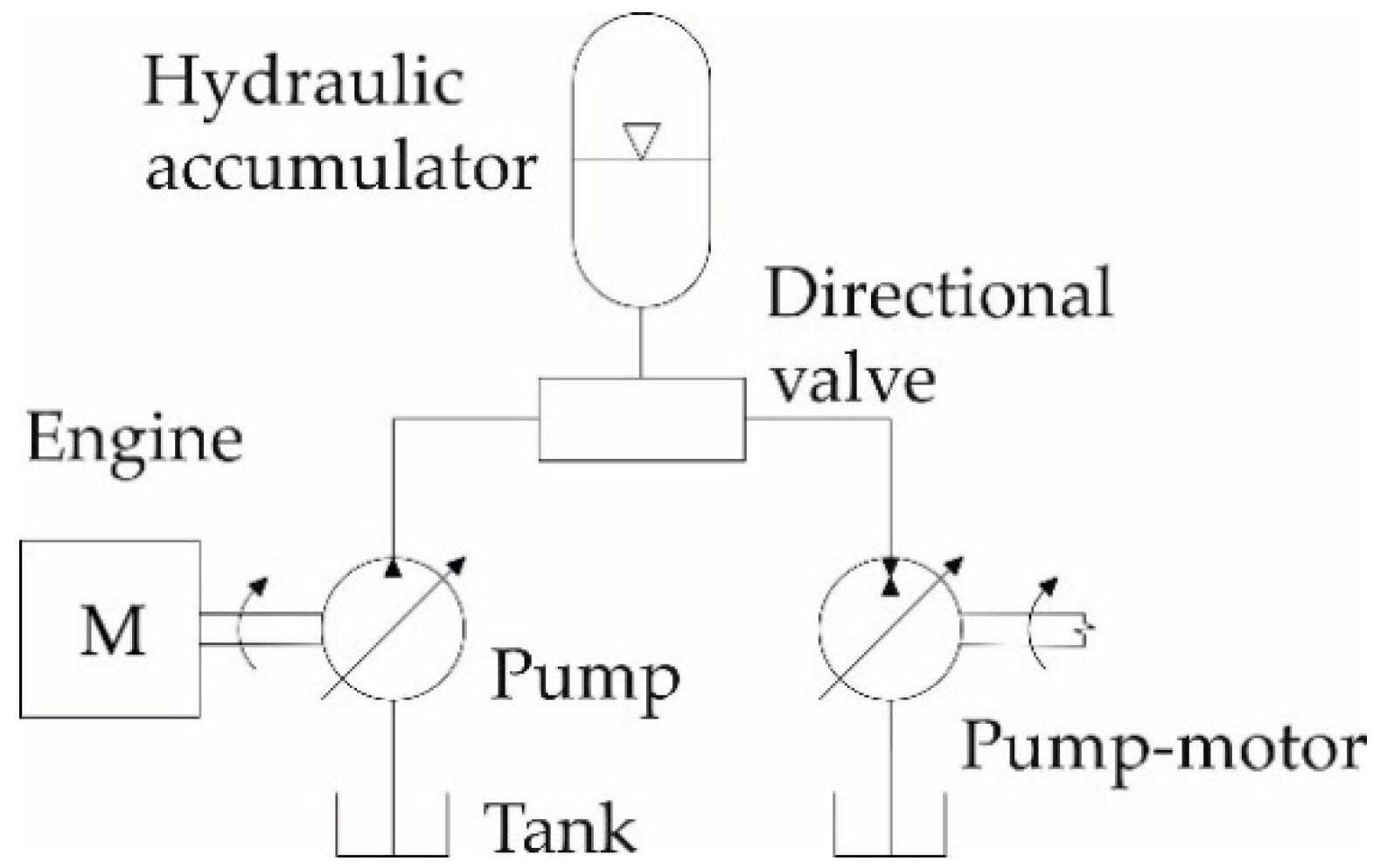
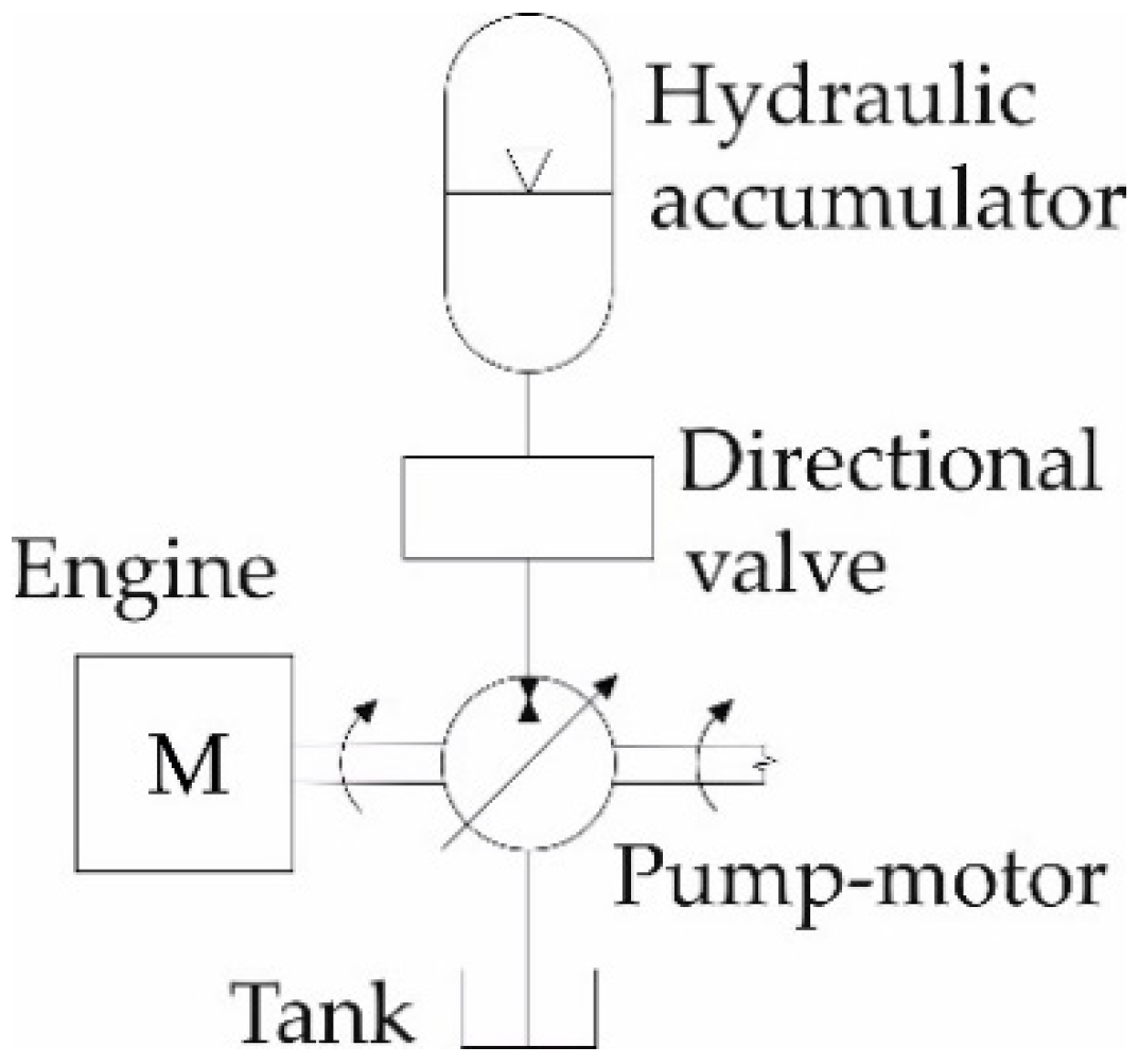
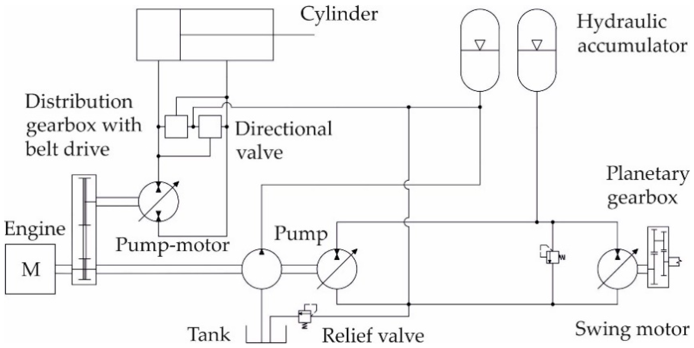
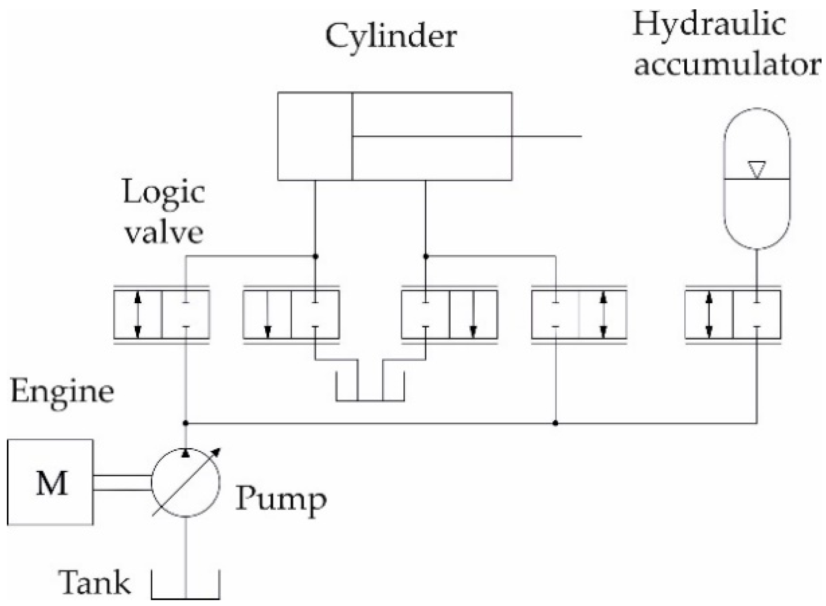
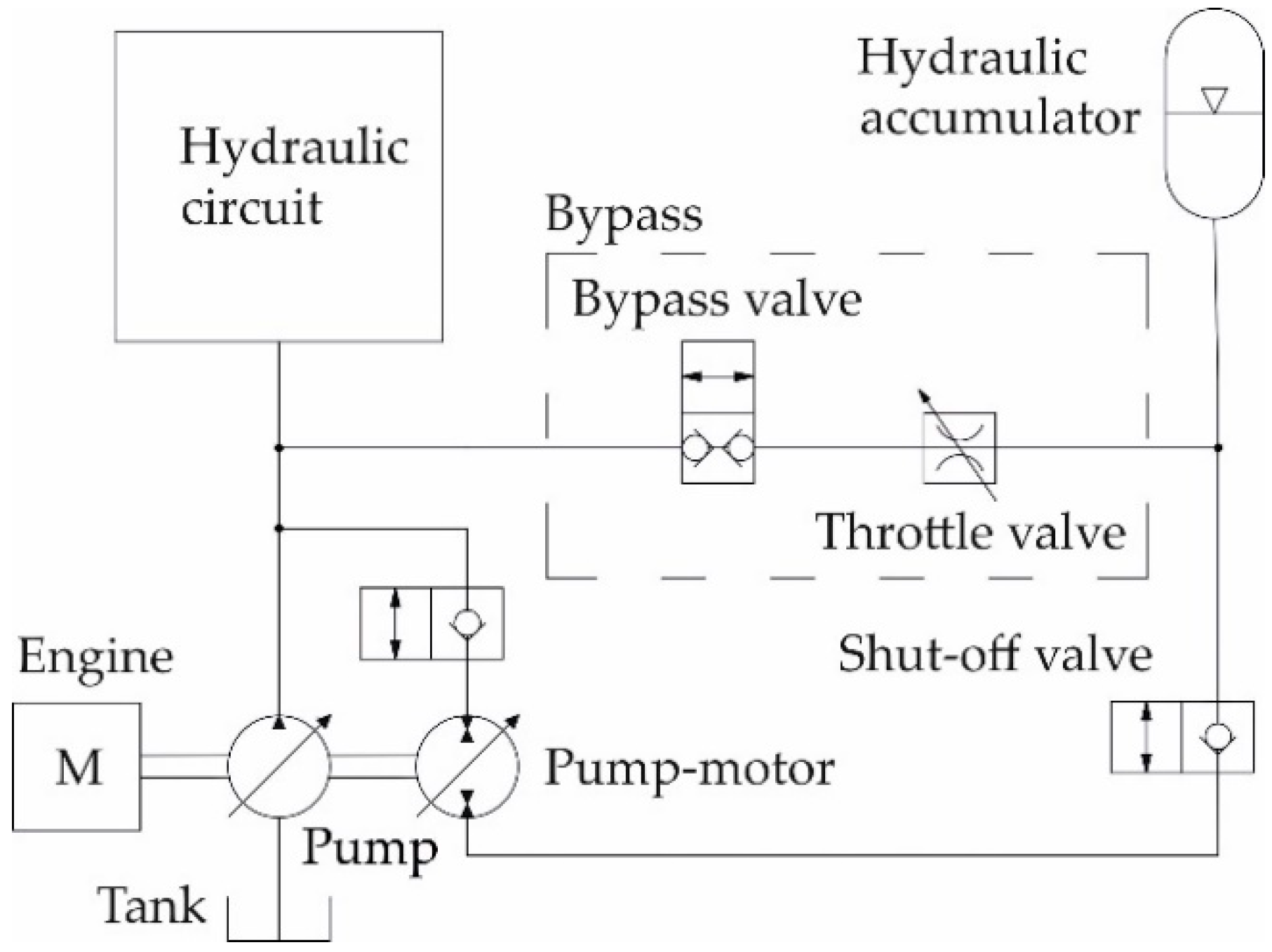
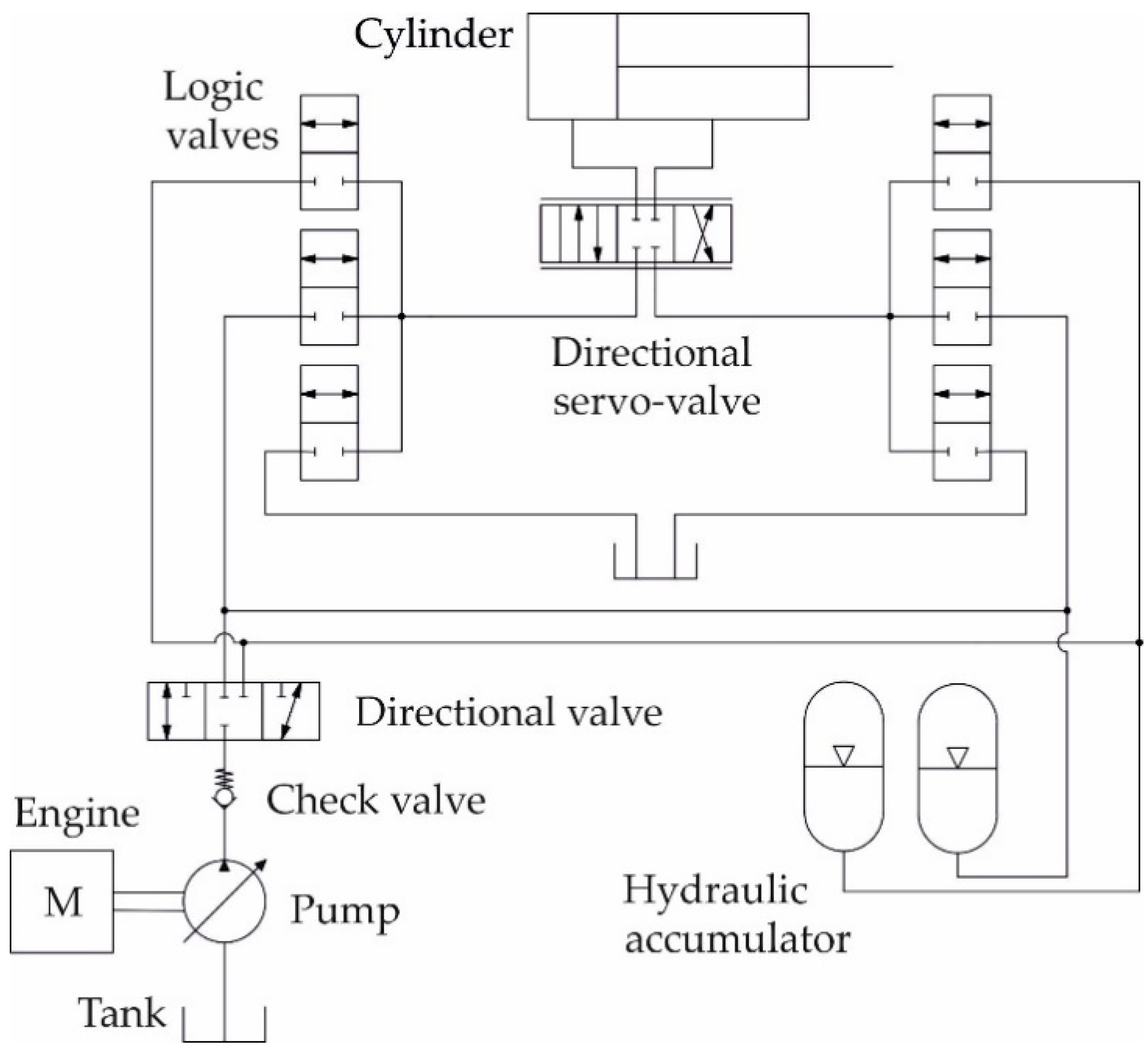
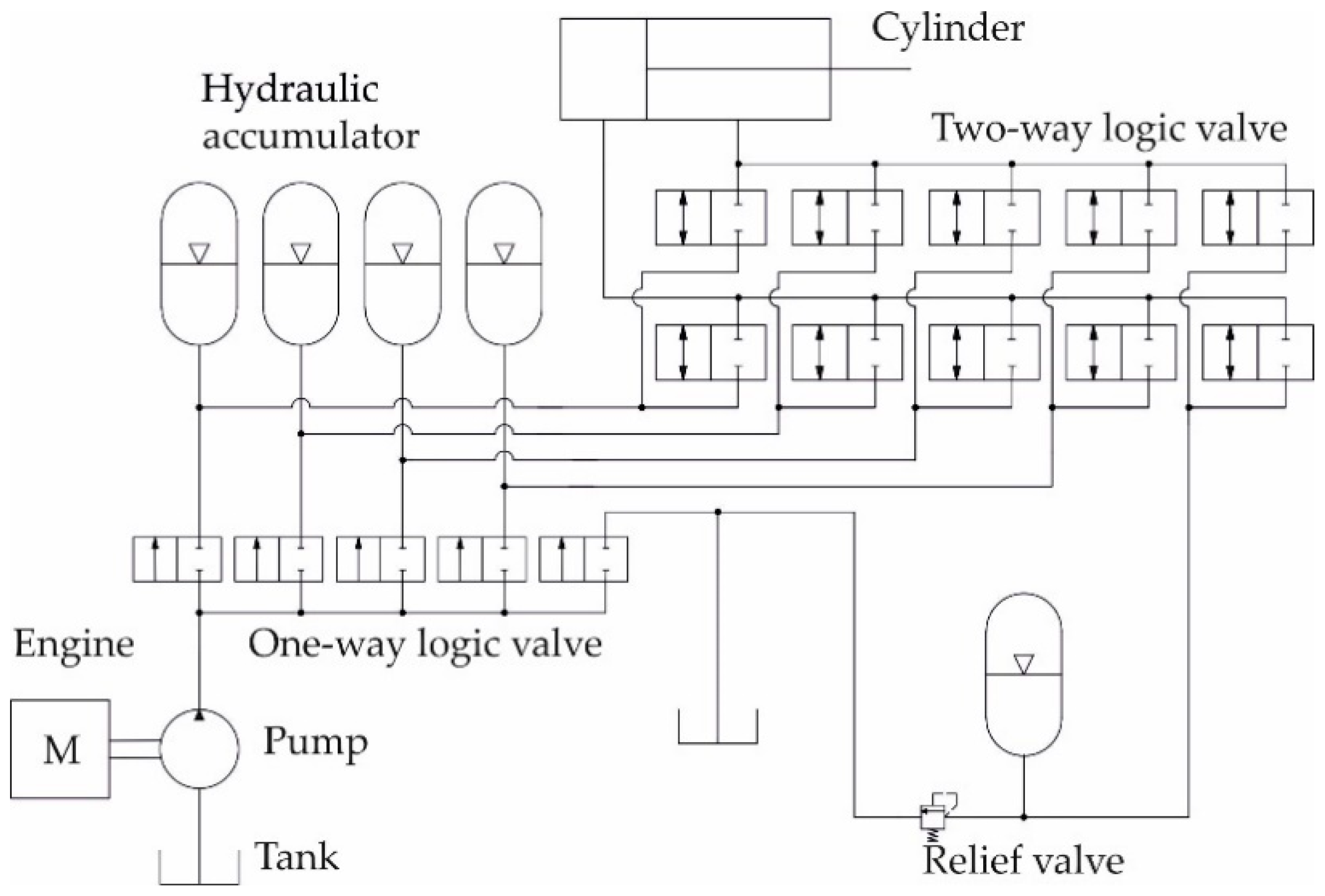
2.2. Hydraulic Hybrids

The method of hybridization uses a hydrostatic pressure system. A hydraulic accumulator is used in all available designs. Bansal [27] showed a pressure tank, in which the incompressible hydraulic fluid is kept under pressure from an external source. Pressure energy of the liquid is converted in the accumulator into the deformation energy of the compressed gas, which is then converted back to the pressure energy at the appropriate moment [28]. Gangwar et al. [29] add that the accumulator allows the hydraulic system to cope with extreme pressure requirements through a less powerful hydraulic pump and also to respond more quickly to a temporary demand. The use of a hydraulic accumulator also smooths the flow pulses caused by the hydraulic pump. Heikkilä [30] stated that hydro-pneumatic accumulators are more advantageous than electrical storage devices thanks to their simplicity and cost-effective design.
Some methods of solutions also use a hydraulic motor with the possibility of hydraulic fluid flow control, which can also work as a hydraulic pump (hereinafter referred to as a motor–generator) [31]. Pivoňka [32] stated that this possibility is offered, for example, by axial piston pumps. In case of low-pressure energy consumption in the operating cycle the motor–generator supplies excess energy into the hydraulic accumulator, and in case of high energy consumption, it can be used for the motor mode depending on the layout of the hydraulic accumulator in the circuit [6].
Hydraulic hybrids can be broken down into series (Figure 5) and parallel (Figure 6) ones according to their arrangement [33]. Hippalgaonkar and Ivantysynova [34] present a series–parallel configuration. The configuration can be called a power split as it is in principle mixed wiring in electro-hybrids. In the case of a series connection, all the mechanical energy is transformed into hydraulic energy and then converted back into mechanical energy. On the other hand, the parallel connection converts mechanical energy into hydraulic energy only in case of a low load of the internal combustion engine and converts it into mechanical energy when the internal combustion engine is loaded heavily to relieve the load [33]. The series–parallel configuration, i.e., the power split configuration, uses both systems and can be seen in Figure 7.
The simplest systems do not currently use such types of hydraulic motor. They use only the accumulator itself, which is connected to the existing open-loop hydraulic circuit. The accumulator is connected by a two-way proportional valve (to the system under pressure), which is connected with the already mentioned circuit, where a hydraulic servo-valve can also be found, which is located on the line upstream from the hydraulic motor [31]. However, a connection from the tank with the pipeline ending under the surface also leads into the servo-valve.
Hydraulic oil is supplied into such systems under pressure by a one-way pump with the possibility of flow control. In case of excess pressure in the system, the accumulator is recharged, which then supplies the necessary pressure into the system in case of a lack of necessity [6]. Linjama et al. [31] called the machines equipped with these types of solutions hybrids without a two-way hydraulic motor with traditional valves. Amrhein and Neumann [35] stated that the system can be modified by moving the accumulator to the suction side of the hydraulic pump, while replacing it with another one that is suitable for a closed-loop hydraulic circuit. The solution enables energy recuperation from the cylinder of the hydraulic crane arm during its lowering.
Linjama et al. [31] showed motor–generator hybrids with logic valves as another method of solution. Their method is similar to the system mentioned above, but upstream of the hydraulic motors there is a system of proportional valves (Figure 8), both the one-way and the two-way types. The two-way proportional valves are located upstream of the entry to the hydraulic motor and are connected to the same section of the hydraulic circuit with one-way valves, which are connected to their own tanks, where their direction of the given fluid flow also leads. The system then does not need the hydraulic servo-valve [31].
In addition to the accumulator, other types of hydraulic hybrids also utilize the already mentioned motor–generator. It is located on the shaft downstream from the primary one-way pump, which supplies pressure to the working hydraulic circuit [6]. The motor–generator itself has its own circuit, a closed-loop circuit [33]. An accumulator is connected in this circuit, upstream of which the electromagnetically controlled check valve is located [6]. Erkkilä et al. [33] mentioned the use of a controlled shut-off valve (Figure 9).
The hydraulic circuit of the motor–generator is then connected to the primary circuit with the one-way pump. Upstream of the point of connection, as stated by Einola [6], the directional valve is used, from which two branches have their outlets, where the first branch is led into the primary circuit and the second one into the hydraulic oil tank. A different method of connection is mentioned by Erkkilä et al. [33] and also by Eniola and Kivi [36] who, instead of a switchboard, again use the same two-way valve with the possibility of fluid flow control in one direction (as for the accumulator), from which the line is then connected to the primary circuit. Machines designed in that way can be called hybrids with an extra pump–motor. The benefit of the described approach is that the flow rates of the pump–motors are summed and the installed displacement does not necessarily increase [31].
The hydraulic flywheel (HFW) drive concept, developed by Bosch Rexroth AG, is able to store the kinetic energy as well as surplus energy in situations when the combustion engine is loaded only partly [37]. The energy storage takes place with help of a battery and a motor–generator which, as mentioned in the text above, can work in the engine and generator modes. At a full load of the combustion engine, the stored hydraulic energy is converted back to mechanical energy, which is led to the shaft coming out of the engine and its load is thus relieved. The advantage of this approach is that it can be installed in parallel with the existing system [31].
The two-pressure system (STEAM) is another solution for hybrid hydraulic drives. The STEAM system has two supply pressures, which are implemented by accumulators and a filling rotary hydraulic pump with the possibility of liquid flow control [38]. There are currently two variants of the solution. The difference between them is the absence of a hydraulic directional servo-valve upstream of the cylinder and the replacement of the logic valves by two-way proportional valves. Figure 10 presents the variant with a servo-valve and logic valves. The system presented significantly reduces fuel consumption [31].
The multi-pressure system is the last system utilized in hydraulic hybrids. The multi-pressure system uses a large number of accumulators, but the pressure energy is supplied to them with the help of one hydraulic pump only. It is, in particular, a one-way pump with an inability of fluid flow control. Linjama et al. [31] stated that it is a complex system from the point of the arrangement of all one-way or two-way logic valves. It is the most energy efficient solution of all alternatives to the hydraulic hybrids mentioned above [39]. A complete diagram of the system can be seen in Figure 11.
There were several machines made with a hydraulic hybrid solution to the present situation but they all were based only on the series configuration. One of them was the forwarder Caribou S 10 made by Ponsse Plc. The hydraulic hybrid was used to test two different systems of hybridization and conventional drive. Specifically, a hybrid solution without a pump–motor with logic valves and a multi-pressure system was used. In both systems, the hydraulic accumulator was connected to the hydraulic circuit of the crane, which allowed the use of a smaller pump. The volume was decreased from 130 cm3 to 71 cm3 [31]. A similar system, however, not specified in great detail, was created in the FORWARDER2020 concept. In the system, energy was recuperated from the lifting cylinder and from clamping the load to the grapple [40]. However, each source of recovered energy had its own battery. In this category of hybrids are included not only forwarders but also harvesters. For example, wheel harvester HSM 405H2 from Hohenloher Spezial-Maschinenbau GmbH & Co. KG (HSM forest), in which the hydraulic accumulator is connected to the hydraulic circuit of the crane and is capable of being fully charged within 4 s [41]. The hydraulic hybrid system uses a series configuration. Ponsse Plc also created a hydraulic hybrid harvester using the model Ergo with a parallel configuration. The concept was to use a pump–motor. In a situation when the pressure in the hydraulic system drops or in the case of a high load of the internal combustion engine, pressure energy from the hydraulic accumulator is released to the pump–motor. Research showed that the pump–motor had problems with the reaction dynamics and therefore the accumulator was also connected to the hydraulic circuit so it could immediately replenish the required pressure [36]. Such an adjustment was called a bypass (Figure 9).

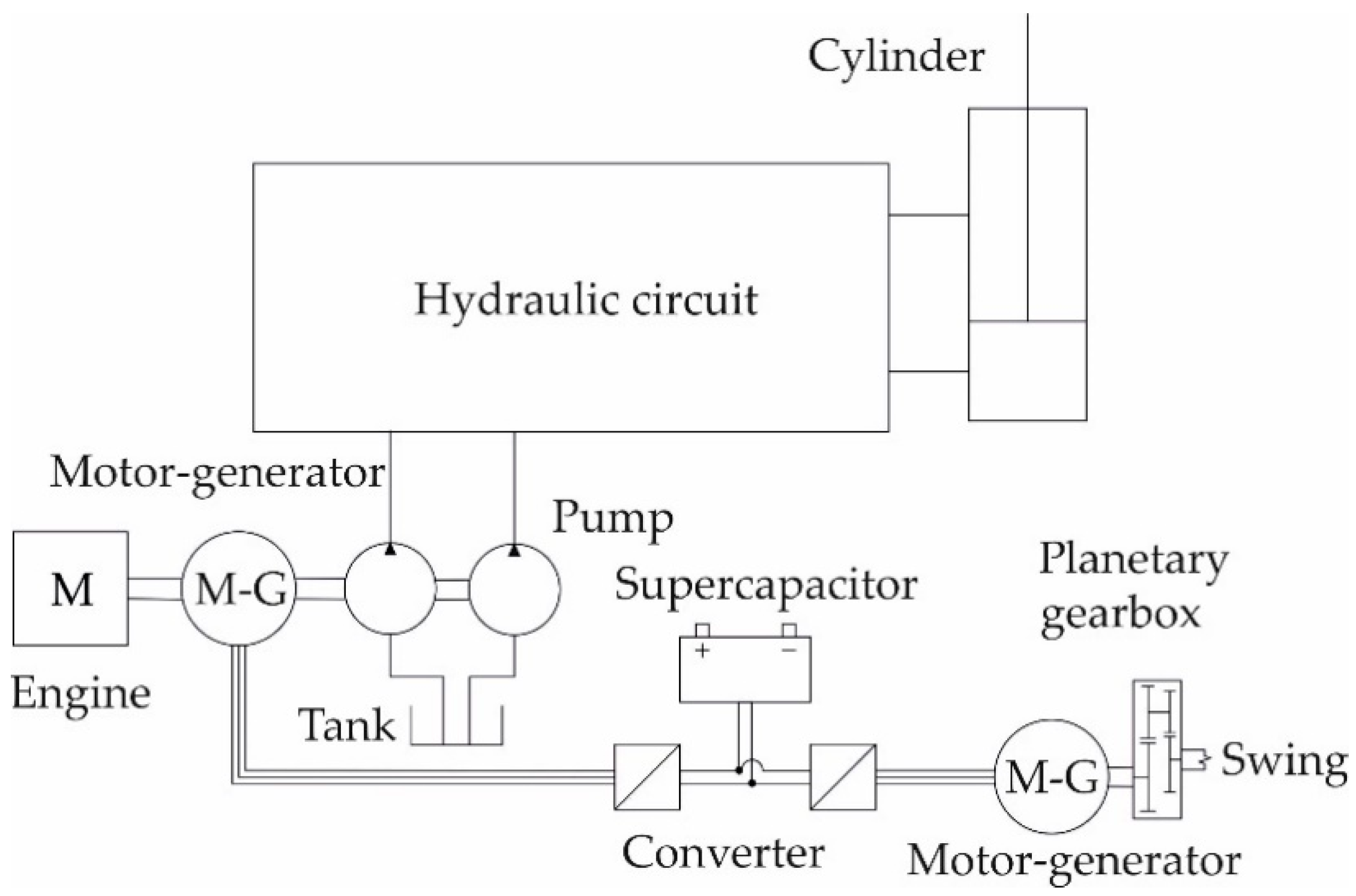
2.3. Electro-Hydraulic Hybrids

At present, the hybrid drives can be broken down, based on the used energy, into the electro-hybrids and the hydraulic hybrids but we can also encounter their combination, i.e., the electro-hydraulic hybrids. The accumulator–hydraulic motor–generator energy regeneration system (AMGERS), mentioned by Lin and Wang (2012) [5], is a typical example. The system works on the same principle as the motor–generator energy regeneration system (MGERS) electro-hybrid. The AMGERS solution differs mainly by the hydraulic accumulator used. It is located between the hydraulic proportional directional valve and the tank. The hydraulic motor is located on the branch (T) leading to the tank and driving the electric generator, with the switchboards and the one-way logic valve located upstream and downstream from it (Figure 12). The electro-hybrid part is the same as in the MGERS system [21]. In the future, however, it may be a solution for forestry machinery.

3. Discussion

At present, there is a need to reduce fuel consumption and thus the costs of harvesting by the relevant machine, including the generated emissions. The hybrid systems described above can solve the highlighted issue. The electro-hybrids or other hybrids can achieve fuel economy benefits ranging anywhere from 10 to 50% [16].
The commonly used electro-hybrid system in forestry practice and manufactured by Logset Oy enables fuel economy benefits of 25% [17]. This is also confirmed by Johnsen (2021) [4], who states economy benefits of 20 to 25% for the same design. According to Eniola (2013) [6], the Elforest forwarder has the same value of fuel savings and electro-hybrid excavators achieve an upper limit of 50% [16]. The hydraulic hybrids achieve a lower fuel consumption [31] in general by 15 to 28%. Lin et al. [15] report savings of up to 40% and even more, which can be achieved as claimed by Linjama et al. [31] by the multi-pressure system. Thanks to their system, the electro-hydraulic hybrids of the AMGERS type are able to reduce the power of the electric motor and the hydraulic motor in the hybrid part by up to 65% [15].
This publication is focused only on the use of hybrid forestry machines. However, the environmental impact of the production of hybrids in the future, especially the production of electrical storage devices containing rare metals which are the reason for the ever-increasing recycling trend, must be taken into account [42,43]. These metals are dangerous for the environment when disposed of and there is an effort to develop electricity storage free of these hazardous metals [44]. The disadvantage of the electricity storage materials may be their life cycle after which they need to be replaced. However, manufacturers in the forestry sector do not mention the life cycle of electro-hybrid systems. The temperature in which the machine will operate and especially the type of storage selected can be problems for the determination of the life cycle. Much research is currently underway on the life cycle of various batteries, supercapacitors, and their combinations for improvement [45,46,47,48,49]. As for the forestry machine manufacturers, very little is known about the type of electricity storage (Table 1). However, in the future, the longevity of electro-hybrids is a good topic for research. Hydraulic hybrids do not have a problem with the battery and its life cycle due to their design and way of storing energy [30]. However, these hybrids have only been tested in the short term or the results are not known, so they could be a good subject for longer-term research.
The strong point of hybrid solutions compared to conventional ones is the lower weight of the machine. In their research on a hybrid forwarder from Elforest AB, Edlund et al. [23] obtained demonstrable results on the lower pressure on the soil that the hybrid machine develops compared to a conventional machine. It should be noted that the conventional machine had eight wheels, while in contrast, the hybrid had only six wheels. In comparison, the hybrid developed a pressure of only 68 kPa, which is 50 kPa less than a conventional machine [23]. An indisputable advantage of the electro-hybrid solution is the better distribution of traction force on the individual wheels [23,24]. The solution of hydraulic hybrids then makes it possible to reduce the size of the pump while maintaining the overall power, or the recuperation from the lifting cylinder then also enables its smoother operation [29,30,31]. However, the undeniable strength of all hybrid solutions is the reduction in fuel consumption and CO2 emissions. This information and other available parameters can be seen in Table 1. A comparison with conventional machines, which is not mentioned here in the text, can be found in Table 2.
The question arises whether or not other possible hybrid systems can be applied to forestry machinery, or whether it is possible to further reduce the size of the engine using the existing possible hybrid solutions. A solution from Volvo Trucks and their combination of an internal combustion engine and a turbo-compound system could be one of the answers to the question. The system uses exhaust gases for driving [50]. The exhaust gases are converted into mechanical energy which is led to the crankshaft of the combustion engine [51]. Turbo-compound is in principle an extra turbine located downstream of the turbo-charger in the exhaust pipeline, which recycles excess heat and exhaust gas energy. By utilizing excess energy, the turbo-compound unit delivers a much higher torque to the crankshaft, thus saving fuel. That principle can be used together with other hybrid solutions.

4. Conclusions

Forest machines offer big possibilities for the use of hybrids. Common drivers of the development of hybrid drive solutions in forest machinery are: low emissions and noise, high performance, fuel efficiency, regulation (emission standards for non-road diesel engines: EU and US EPA with continuous restriction), and public image. The current technical and technological development of hybrid drive systems, as well as their components, has led to significant improvements in drive performance and thus better performance of the new generation of forest machines. Improved energy efficiency through the use of hybrid propulsion systems in forest machines would result in a significant reduction in greenhouse gas emissions and possibly lower maintenance costs. Variable fuel prices, stricter exhaust emission regulations, and lower prices of electrical components will accelerate the development and application and share of different types of hybrid drives in forest machines [52].
Today, we consider hybrid drive solutions as an alternative to a purely electric vehicle solution until the time when, through further development, fuel cells or passive energy sources will be sufficient to meet the operating energy requirements of forest machines.
Future development of pure electric forest machines as well as for hybrid solutions is a very important task for forest engineering research activities because forest engineers need to define the energy requirements of different types of forest machines performing operations in different terrain conditions. Such research results will be a platform for future development of electric forest machines.
We need to be aware that such solutions at the beginning will increase purchase prices of machines because they could represent an element of risk to companies which produce forest machines. Additionally, production series and sales volumes of different types of forest machines are significantly lower than other specialized machines (agricultural, construction, material handling machines), which poses a risk to manufacturers in terms of return on investment in the development of hybrid drives.

Author Contributions

Conceptualization, V.M. and M.Š.; methodology, Z.P.; validation, J.K., Z.P., and H.K.; writing—original draft preparation, V.M. and M.Š.; writing—review and editing, Z.P. and J.K.; visualization, V.M. and M.B.; supervision, M.Š.; project administration, H.K.; funding acquisition, M.Š. All authors have read and agreed to the published version of the manuscript.

Funding

This research was supported by the European Regional Development Fund in the scope of European Union Operational Programme “Competitiveness and Cohesion «under the grant KK.01.1.1.04.0010» (Development of hybrid skidder—HiSkid”) within the scope of European Union Operational Programme “Competitiveness and Cohesion” 2014–2020 (2014HR16M1OP00-1.2).

Institutional Review Board Statement

Not applicable.

Informed Consent Statement

Not applicable.

Data Availability Statement

Not applicable.

Acknowledgments

This research was supported and encouraged by an Erasmus+ Traineeship agreement between the Faculty of Forestry and Wood Technology of Mendel University in Brno and the Faculty of Forestry and Wood Technology of the University of Zagreb.

Conflicts of Interest

The authors declare no conflict of interest.

References

  1. Solouk, A.; Shakiba-Herfeh, M.; Arora, J.; Shahbakhti, M. Fuel consumption assessment of an electrified powertrain with a multi-mode high-efficiency engine in various levels of hybridization. Energy Convers. Manag. 2018, 155, 100–115. [Google Scholar] [CrossRef]
  2. Klvač, R.; Ward, S.; Owende, P.M.O.; Lyons, J. Energy Audit of wood harvesting systems. Scand. J. For. Res. 2003, 18, 176–183. [Google Scholar] [CrossRef]
  3. Sellgren, U. Engineerimg Education for Industrial Innovation. Available online: https://www.researchgate.net/publication/266291963_ENGINEERING_EDUCATION_FOR_INDUSTRIAL_INNOVATION (accessed on 10 January 2021).
  4. Johnsen, T. Logset 12H GTE Hybrid-Electric Harvester. Available online: https://www.forestry.com/editorial/logset-12h-gte-electric-hybrid-harvester/ (accessed on 28 February 2021).
  5. Lin, T.; Wang, Q. Hydraulic accumulator-motor-generator energy regeneration system for a hybrid hydraulic excavator. Chin. J. Mech. Eng. 2012, 25, 1121–1129. [Google Scholar] [CrossRef]
  6. Einola, K. Prestudy of a Power Management of a Cut-To-Length Forest Harvester with a Hydraulic Hybrid System. In Proceedings of the 13th Scandinavian International Conference on Fluid Power, Linköping, Sweden, 3–5 June 2013; pp. 71–83. [Google Scholar]
  7. Roubíček, O. Příručka techniky, volby a užití vybraných druhů. In Elektrické Motory a Pohony, 1st ed.; BEN-technická literatura: Prague, Czech Republic, 2004; pp. 1–191. [Google Scholar]
  8. Kůs, V. Elektrické Pohony a Výkonová Elektronika, 2nd ed.; University of West Bohemia in Pilsen: Pilsen, Czech Republic, 2016; pp. 1–181. [Google Scholar]
  9. Ishida, K.; Higurashi, M. Hybrid wheel loaders incorporating power electronics. Hitachi Rev. 2015, 64, 398–402. [Google Scholar]
  10. Procházka, P.; Pazdera, I.; Cipín, R. Hybrid Tree Harvester Machine with Battery Powered Hydro-electric Drive. ECS Trans. 2019, 95, 349–354. [Google Scholar] [CrossRef]
  11. Tkotz, K. Příručka pro Elektrotechnika, 2nd ed.; Handlíř, J., Translator; Verlag Europa-Lehrmittel: Haan-Gruiten, Germany, 2014; pp. 1–624. [Google Scholar]
  12. Blahovec, A. Elektrotechnika III: (Příklady a Ulohy), 6th ed.; Informatorium: Prague, Czech Republic, 2015; pp. 1–291. [Google Scholar]
  13. Sani, A.; Siahaan, S.; Mubarakah, N.; Suherman, S. Supercapacitor performance evaluation in replacing battery based on charging and discharging current characteristics. IOP Conf. Series: Mater. Sci. Eng. 2018, 309, 1–6. [Google Scholar] [CrossRef]
  14. Hromádko, J. Speciální Spalovací Motory a Alternativní Pohony: Komplexní Přehled Problematiky pro Všechny Typy Technických Automobilních Škol, 1st ed.; Grada Publishing a.s.: Prague, Czech Republic, 2012; pp. 1–160. [Google Scholar]
  15. Lin, T.; Wang, Q.; Hu, B.; Gong, W. Development of hybrid powered hydraulic construction machinery. Autom. Constr. 2010, 19, 11–19. [Google Scholar] [CrossRef]
  16. Lajunen, A.; Suomela, J.; Pippuri, J.; Tammi, K.; Lehmuspelto, T.; Sainio, P. Electric and Hybrid Electric Non-Road Mobile Machinery–Present Situation and Future Trends. World Electr. Veh. J. 2016, 8, 172–183. [Google Scholar] [CrossRef] [Green Version]
  17. Logset Oy. Logset 12H GTE Hybrid. Available online: https://www.logset.com/harvesters/logset-12h-gte-hybrid (accessed on 3 January 2021).
  18. Anon. The Most Productive Hybrid Forest Harvester in the World. Available online: https://www.electrificationstory.com/logset-hybrid-forest-harvester/ (accessed on 22 March 2021).
  19. Sainio, P.; Minav, T.; Lajunen, A.; Tammi, K.; Laurila, L.; Pyrhönen, J.; Pippuri, J.; Kukkonen, S. Technology Road Map for Hybrid and Electrical Drivetrain of Non-Road Mobile Machinery. Available online: https://docplayer.net/48217321-Technology-road-map-for-hybrid-and-electrical-drivetrain-of-non-road-mobile-machinery.html/ (accessed on 15 April 2021).
  20. Kühmaier, M.; Harrill, H.; Ghaffariyan, M.R.; Hofer, M.; Stampfer, K.; Brown, M.; Visser, R. Using Conjoint Analyses to Improve Cable Yarder Design Characteristics: An Austrian Yarder Case Study to Advance Cost-Effective Extraction. Forests 2019, 10, 165. [Google Scholar] [CrossRef] [Green Version]
  21. Lin, T.; Huang, W.; Ren, H.; Fu, A.; Liu, Q. New compound energy regeneration system and control strategy for hybrid hydraulic excavators. Autom. Constr. 2016, 68, 11–20. [Google Scholar] [CrossRef]
  22. Stodart, N. El-forest hybrid forwarder. For. J. 2010, 10, 20–21. [Google Scholar]
  23. Edlund, J.; Bergeten, U.; Lögren, B. Effects of two different forwarder steering and transmission drive systems on rut dimensions. J. Terramechanics 2012, 49, 291–297. [Google Scholar] [CrossRef]
  24. Rong-feng, S.; Xiaozhen, Z.; Chengjun, Z. Study on Drive System of Hybrid Tree Harvester. Sci. World J. 2017, 1–7. [Google Scholar] [CrossRef] [Green Version]
  25. Zemánek, T.; Neruda, J.; Ulrich, R.; Vítek, O.; Procházka, P. Operational evaluation of a timber trailer with the hybrid drive. In Proceedings of the 52nd International Symposium on Forestry Mechanization, Sopron, Hungary, 6–9 October 2019; pp. 162–171. [Google Scholar]
  26. Laitila, J.; Prinz, R.; Routa, J.; Kokko, K.; Kaksonen, P.; Suutarien, J.; Eliasson, L. Prototype of Hybrid Technology Chipper-D4.6. Available online: https://www.luke.fi/wp-content/uploads/2016/03/D-4.6-Demoreport-hybrid-chipper.pdf (accessed on 15 April 2021).
  27. Bansal, R.K. A Textbook of Fluid Mechanics and Hydraulic Machines, 9th ed.; Laxmi Publications Ltd.: New Delhi, India, 2005; pp. 1041–1070. [Google Scholar]
  28. Pavlok, B.; Hružík, L.; Bova, M. Hydraulická Zařízení Strojů, 1st ed.; VSB-Technical University of Ostrava: Ostrava, Czech Republic, 2007; pp. 1–116. [Google Scholar]
  29. Gangwar, G.K.; Tiwari, M.; Singh, R.B.; Dasgupta, K. Study of different type of hydraulic accumulators, their characteristics and applications. Int. J. Res. Aeron. Mech. Eng. 2014, 2, 56–63. [Google Scholar]
  30. Heikkilä, M. Energy Efficient Boom Actuation Using a Digital Hydraulic Power Management System. Ph.D. Thesis, Tampere University of Technology, Tampere, Finland, June 2016. [Google Scholar]
  31. Linjama, M.; Huova, M.; Tammisto, J.; Heikkilä, M.; Tikkanen, S.; Kajaste, J.; Paloniitty, M.; Pietola, M. Hydraulic hybrid working machines project-lessons learned. In Proceedings of the 16th Scandinavian International Conference on Fluid Power (SICFP 2019), Tampere, Finland, 22–24 May 2019; pp. 423–437. [Google Scholar]
  32. Pivoňka, J. Příručka Hydraulických Pohonů, 1st ed.; SNTL: Prague, Czech Republic, 1969; pp. 1–478. [Google Scholar]
  33. Erkkilä, M.; Bauer, F.; Feld, D. Universal Energy Storage and Recovery System–A Novel Approach for Hydraulic Hybrid. In Proceedings of the 13th Scandinavian International Conference on Fluid Power, Linköping, Sweden, 3–5 June 2013; pp. 45–52. [Google Scholar]
  34. Hippalgaonkar, R.; Ivantysynova, M. A Series-Parallel Hydraulic Hybrid Mini-excavator with Displacement Controlled Actuator. In Proceedings of the 13th Scandinavian International Conference on Fluid Power, Linköping, Sweden, 3–5 June 2013; pp. 31–42. [Google Scholar]
  35. Amrhein, J.; Neumann, U. PRB–regeneration of potential energy while boom-down. In Proceedings of the 8th International Fluid Power Conference, Dresden, Germany, 26–28 March 2012; pp. 63–71. [Google Scholar]
  36. Einola, K.; Kivi, A. First experimental results of a hydraulic hybrid concept system for a cut-to-length forest harvester. In Proceedings of the 14th Scandinavian International Conference on Fluid Power, Tampere, Finland, 20–22 May 2015; pp. 52–64. [Google Scholar]
  37. Bosch Rexroth AG. Hydraulic Flywheel HFW. Available online: https://www.boschrexroth.com/en/xc/products/product-groups/mobile (accessed on 10 January 2021).
  38. Vukovic, M.; Leifeld, R.; Murrenhoff, H. Reducing Fuel Consumption in Hydraulic Excavators—A Comprehensive Analysis. Energies 2017, 10, 687. [Google Scholar] [CrossRef] [Green Version]
  39. Huova, M.; Aalto, A.; Linjama, M.; Huntala, K.; Lantela, T.; Pietola, M. Digital hydraulic multipressure actuator–the concept, simulation study and first experimental results. Int. J. Fluid Power 2017, 18, 141–152. [Google Scholar] [CrossRef] [Green Version]
  40. Anon. FORWARDER2020. Available online: https://www.forwarder2020-project.eu/downloads-links/ (accessed on 15 April 2021).
  41. Hohenlohe, F. Phlegmatisierung als Tugend in der Mobilhydraulik Das Energiespeichersystem des Kranvollernters HSM 405H2. In Hybridantriebe für Mobile Arbeitsmaschinen, 1st ed.; KIT Scientific Publishing: Karlsruhe, Germany, 2011; pp. 151–162. [Google Scholar]
  42. Al-Thyabat, S.; Nakamura, T.; Shibata, E.; Iizuka, A. Adaptation of minerals processing operations for lithium-ion (LiBs) and nickel metal hydride (NiMH) batteries recycling: Critical review. Miner. Eng. 2013, 45, 4–17. [Google Scholar] [CrossRef]
  43. Ruffino, B.; Zanetti, M.; Marini, P. A mechanical pretreatment process for the valorization of useful fractions from spent batteries. Resour. Conserv. Recycl. 2013, 55, 309–315. [Google Scholar] [CrossRef]
  44. Dyatkin, B.; Presser, V.; Heon, M.; Lukatskaya, M.R.; Beidaghi, M.; Gogotsi, Y. Development of a green supercapacitor composed entirely of environmentally friendly materials. ChemSusChem 2013, 6, 2269–2280. [Google Scholar] [CrossRef]
  45. Propp, K.; Marinescu, M.; Auger, D.J.; O’Neill, L.; Fotouhi, A.; Somasundaram, K.; Offer, G.J.; Minton, G.; Longo, S.; Wild, M.; et al. Multi-temperature state-dependent equivalent circuit discharge model for lithium-sulfur batteries. J. Power Sources 2016, 328, 289–299. [Google Scholar] [CrossRef] [Green Version]
  46. Huang, S.; Zhu, X.; Sarkar, S.; Zhao, Y. Challenges and opportunities for supercapacitors. APL Mater. 2019, 7, 100901. [Google Scholar] [CrossRef]
  47. Sedlakova, V.; Sikula, J.; Sedlak, P.; Cech, O.; Urrutia, L. A Simple Analytical Model of Capacity Fading for Lithium–Sulfur Cells. IEEE Trans. Power Electron. 2019, 34, 5779–5786. [Google Scholar] [CrossRef]
  48. Ayodele, T.R.; Ogunjuyigbe, A.S.O.; Olateju, B.E. Improving battery lifetime and reducing life cycle cost of a PV/battery system using supercapacitor for remote agricultural farm power application. J. Renew. Sustain. Energy 2018, 10, 013503. [Google Scholar] [CrossRef]
  49. Pozo, B.; Garate, J.I.; Ferreiro, S.; Fernandez, I.; Fernandez de Gorostiza, E. Supercapacitor Electro-Mathematical and Machine Learning Modelling for Low Power Applications. Electronics 2018, 7, 44. [Google Scholar] [CrossRef] [Green Version]
  50. Payri, F.; Luján, M.J.; Guardiola, C.; Pla, B. A challenging future for the IC engine: New technologies and the control role. Oil Gas Sci. Technol. 2015, 70, 15–30. [Google Scholar] [CrossRef] [Green Version]
  51. Dahl, J.; Wassén, H.; Santin, O.; Herceg, M.; Lansky, L.; Pekar, J.; Pachner, D. Model Predictive Control of a Diesel Engine with Turbo Compound and Exhaust After-Treatment Constraints. IFAC-PapersOnLine 2018, 51, 349–354. [Google Scholar] [CrossRef]
  52. Anon. EV Technologies in Working Machinery–Global View. Finpro, 2010. Available online: http://www.finpro.fi/documents/10304/82c1b231-9f5a-44a0-b2e6-b94fbaf53105 (accessed on 16 June 2011).
Figure 1. Hybrid drive classification.
Energies 14 02793 g001
Figure 2. Electro-hybrid configuration.
Energies 14 02793 g002
Figure 3. Types of electro-hybrid drive arrangement.
Energies 14 02793 g003
Figure 4. Hybrid system of Komatsu Ltd.
Energies 14 02793 g004
Figure 5. Series configuration.
Energies 14 02793 g005
Figure 6. Parallel configuration.
Energies 14 02793 g006
Figure 7. Power split (series–parallel) configuration.
Energies 14 02793 g007
Figure 8. Hybrid without pump–motor with logic valves.
Energies 14 02793 g008
Figure 9. Hybrid solution with pump–motor.
Energies 14 02793 g009
Figure 10. STEAM system with a servo-valve and logic valves.
Energies 14 02793 g010
Figure 11. Multi-pressure system.
Energies 14 02793 g011
Figure 12. AMGERS.
Figure 12. AMGERS.
Energies 14 02793 g012
Table 1. Characteristics of hybrid forest machines.
Type of HybridizationMachine TypeFuel Consumption Reduction [%]CO2 Emission Reduction [%]Power of Combustion Engine [kW]Power of Hybrid System [kW]Accumulator Type/Capacity
Electro-hybrid8H GTE Hybrid by Logset Oy (harvester)up to 2515–30214104Supercapacitor/-
12H GTE Hybrid by Logset Oy (harvester)up to 2515–30214175Supercapacitor/-
Harvester by Agama a.s. (harvester)---23Battery/82 Ah, 12 V
910EH by ProSilva Oyj (harvester)40-60 *60 (2 el. motors)Battery/-
KX 800e by Koller GmBH (excavator based yarder)--212800 per winchSupercapacitor/-
HB365 By Komatsu (excavator)20 (average)20 (average)202-Supercapacitor/-
E70 by New Holland (excavator)404027 **20Li-on battery/288 V
ZH210LC by Hitachi Ltd. (excavator)around 20around 20122-Double-layer supercapacitor/-
F14 by Elforest AB (forwarder)20–50-6030 per wheelBattery/84 V
Harvester by Rong-Feng [24] (harvester)--6060 per bogie axleLi-on battery/105 kW
AGA LV 10 HP by Agama a.s. (wood trailer)35-9718Li-on battery/16 kWh
C 860 H by Kesla Oyj (wood chipper)20–3520–35160-Supercapacitor/-
Hydraulic hybridCaribou S10 by Ponsse Plc. (forwarder) ***28-91-Hydraulic accumulator/20 L
Caribou S10 by Ponsse Plc. (forwarder) ****36-91-Two hydraulic accumulator/10 L × 2
FORWARDER 2020—HSM 208F 12t by HSM forest (forwarder)30-185-Two hydraulic accumulators/-
HSM 405H2 by HSM forest (harvester)20-20590Hydraulic accumulator/60 L
Ergo by Ponsse Plc. (harvester)--21071Hydraulic accumulator/50 L
* Engine downsizing from 155 kW to 60 kW. ** Engine downsizing from 40 kW to 27 kW. *** Hybrid without a pump–motor with logic valves. **** Hybrid with multi-pressure system.
Table 2. Strengths and weaknesses of hybrid machines in forestry.
StrengthsWeaknesses
Lower fuel consumption
Better ergonomics (less noise, vibration, and exhaust emission)
Smooth variable continuous power to wheels, drums, hydraulic pump, etc.
Environmentally friendly operating (less GHG * and PM ** emissions)
Easier operating (automated or remote operation control)
Lower physical workload
Lighter machines
Improved energy storage technology (smaller, lighter batteries, supercapacitors, and hydraulic accumulators with higher energy density)
Better efficiency of propulsion motors
Shortage of fossil fuels
Purchase price (30–50% higher than conventional)
Electrical storage
Heavier and more complex systems
Low energy density of battery and supercapacitor
Overheating of energy storage devices
More demanding maintenance
Life cycle of battery and supercapacitor
Increase in battery and supercapacitor price
Shortage of raw materials for battery and supercapacitor production
Environmental impacts for production and disposal (recycling) of batteries, supercapacitors
Potential hazard of fluid leakage to environment
* GHG—greenhouse gas. ** PM—particulate matter.
Publisher’s Note: MDPI stays neutral with regard to jurisdictional claims in published maps and institutional affiliations.

