Article

Impedance Reshaping Control Strategy for Improving Resonance Suppression Performance of a Series-Compensated Grid-Connected System

College of Electrical and Information Engineering, Hunan University, Changsha 410082, China
*
Author to whom correspondence should be addressed.
Energies 2021, 14(10), 2844; https://doi.org/10.3390/en14102844
Submission received: 29 March 2021 / Revised: 4 May 2021 / Accepted: 11 May 2021 / Published: 14 May 2021

Abstract

:
In the series-compensated grid-connected system (SCGCS), there is an impedance interaction between the inverter impedance and the grid impedance that is prone to cause resonance in the SCGCS. In this paper, firstly, considering the effects of the phase-locked loop (PLL), current-loop, and frequency coupling, the broadband impedance model of the SCGCS is established. The stability of the SCGCS is analyzed by the impedance-based Nyquist stability criterion. It is found from the stability analysis that the impedance interaction between the inverter impedance and the grid impedance is the leading cause of the resonance. An impedance reshaping based resonance suppression method is proposed to suppress the resonance. The phase characteristics of the inverter equivalent output impedance are reshaped from the perspective of impedance. The phase margin at the intersection frequency of the inverter impedance and the grid impedance is improved. The proposed resonance suppression approach mainly consists of reshaping the current loop impedance and the novel phase-locked loop impedance. Finally, simulations and experiments are used to verify the feasibility of the resonance analysis and the effectiveness of the proposed control strategy.

1. Introduction

With the rapid development of renewable energy generation [1] and smart grids [2] based on renewable energy sources (RES), many distributed generation (DG) systems are connected to the grid via power electronic interfacing converters. This not only solves the problem of a global energy shortage, but also brings new challenges to the safe operation of the grid at the same time. Power stations based on renewable energy are usually far away from big cities and are distributed in remote areas such as on islands and in deserts. Series compensation transmission lines are usually used in renewable energy power generation systems because they have the advantage of increasing transmission capacity [3,4].
The increase in renewable energy generation capacity may increase the risk of system oscillations [5], which will not only severely restrict the use of renewable energy, but even affect the stable operation of the system. Therefore, to solve these problems, the stability analysis of grid-connected inverters is very important for the safe operation of the entire grid system [6]. At present, the commonly used methods for analyzing the stability of grid-connected inverter systems mainly include impedance-based methods and state-space methods [7]. Compared with the state-space method, the impedance-based method only needs to establish an impedance model for each subsystem, and therefore, is simple and easy to implement, and is widely used to analyze the stability of the grid-connected inverters [8].
Establishing a comprehensive and accurate grid-connected inverter model is the basis for studying the mechanism of resonance. According to the different reference frames, impedance-based methods can mainly be divided into two types. One is the dq impedance model [9,10,11], and the other is the sequence impedance model [12]. The former is built using the synchronous reference frame, and the latter is built using the stationary reference frame. Reference [13] has proven that the sequence impedance model and the dq impedance model are equivalent when considering frequency coupling. It has become an essential method for analyzing inverter-based systems’ stability because the sequence impedance model can be directly measured and has a simple form [12]. Therefore, the sequence impedance method is used to analyze resonance. However, in regard to the current research about the SCGCS oscillation problem, the impedance model established does not consider the influence of frequency coupling.
Since these resonance accidents occurred, research on the modeling and damping control strategies of the SCGCS has attracted more and more attention. However, when the grid-connected inverter adopts a quasi-proportional resonant (QPR) control, the oscillation problem caused by the impedance interaction of the series compensation system is rarely mentioned. Resonance may also appear on the connecting lines between multiple grid-connected systems [14], especially when the penetration rate of renewable energy reaches a certain level. This article focuses on mitigating the resonance caused by the impedance interaction between the inverter and the SCGCS. Additionally, by adding other equipment [15,16], or improving the control strategy [17,18,19,20,21], it can also result in oscillation suppression, but in doing so will bring unnecessary energy loss. In this paper, the resonance was suppressed by impedance reshaping of the controller and did not require costly devices to avoid resonance. Experiments on the laboratory test platform and simulations on the full-scale system proved the effectiveness of the method at different compensation levels.
This paper established the broadband sequence impedance model and studied the stability of the SCGCS. It revealed that the resonance phenomenon between the inverter and the SGCCS is caused by impedance interaction, and proposed a control strategy based on impedance reshaping to suppress the resonance. The rest of the paper is organized as follows. In Section 2, the broadband impedance model of the grid-connected inverter will be derived based on the harmonic linearization theory, and the causes of resonance are analyzed. In Section 3, the impedance reshaping control strategy for resonance suppression is introduced, and the mechanisms of the proposed strategy for resonance suppression is analyzed. Experimental results are presented in Section 4. Section 5 concludes this article.

2. Modeling and Resonance Analysis of the SCGCS

2.1. The Broadband Impedance Model of the Inverter

Figure 1 shows the topology scheme of the SCGCS. vdc represents the dc-side voltage in the grid-connected inverter mode. It is regarded as a constant value used in conjunction with energy storage equipment. ea, eb, and ec are the inner electric potentials of the inverter; ia, ib, and ic are the currents of filter inductance Lf; ua, ub, and uc are the point of common coupling (PCC) voltages; ug is the grid voltages; Lf, Cf, and Rf represent the filter inductance, filter capacitance, and damping resistance, respectively; Lg, Rg, and Cg represent the grid inductance, resistance and capacitive series-compensated; Zg presents the grid impedance, and Zinv presents the impedance of the grid-connected inverter.
The impedance model of the inverter that considers the effects of the PLL, the current-loop, and the frequency coupling is derived in this section using the harmonic linearization method. In order to obtain the impedance model of the inverter, it is necessary to inject a positive sequence disturbance voltage with a frequency of fp at the PCC point. According to the frequency-coupling effects, injecting a positive-sequence disturbance voltage at the frequency fp into the grid-connected inverter system will not only generate a positive-sequence response current at the frequency fp, but also generate a response current at the coupling frequency fp-2f1 [22]. The phase-A voltage of the inverter can be expressed in the time domain and the frequency domain as follows:
v a t = V 1 cos ( 2 π f 1 t ) + V p cos ( 2 π f p t + φ v p ) + V p 2 cos ( 2 π f p 1 t + φ v p 1 )
where V1 is the amplitude of the fundamental voltage, Vp is the disturbance voltage at fp, and Vp2 is the voltage at fp1, respectively; f1 is the fundamental frequency; φvp is the initial phase angle of Vp, and φvp2 is the initial phase angle of Vp2.
V a f = V ± 1 ,     f = ± f 1 v ± p ,   f = ± f p v ± p 2 , f = ± f p 2 f 1
where V ± 1 = V 1 / 2 ; v ± p = V p / 2 e ± j φ v p ; v ± p 2 = V p 2 / 2 e ± j φ v p 2 .
I a f = I ± 1 ,     f = ± f 1 i ± p , f = ± f p i ± p 2 , f = ± f p 2 f 1 , M a f = M ± 1 ,     f = ± f 1 m ± p , f = ± f p m ± p 2 , f = ± f p 2 f 1
where I ± 1 is the fundamental current, i ± p is the disturbance current response at fp, and i ± p 2 is the disturbance current response at fp1, respectively; M ± 1 , m ± p and m ± p 2 are modulating signals of phase-A.
According to the control diagram of the inverter, as the abc-αβ is a linear transformation, it is not affected by the disturbance of the PLL. The frequency–domain expression of iα and iβ can be obtained as follows:
I α f = G i s I ± 1 ,     f = ± f 1 G i s i ± p , f = ± f p G i s i ± p 2 , f = ± f p 2 f 1 , I β f = j G i s I ± 1 ,     f = ± f 1 j G i s i ± p , f = ± f p ± j G i s i ± p 2 , f = ± f p 2 f 1
where Gi(s) = 1/(1 + sTi) represents the transfer function of the input current sampling filter and Ti is the sampling period of the current.
Furthermore, according to the small signal model of the phase-locked loop, we can get:
cos θ P L L = 1 2 ,                                 f = ± f 1 1 2 T P L L s j ω 1 G v s v ± p v ± p 2 ,       f = ± f p 1 2 T P L L s + j ω 1 G v s v ± p v ± p 2 ,       f = ± f p 2 f 1
sin θ P L L = j 2 ,                               ± f 1 1 2 T P L L s j ω 1 G v s j v ± p ± j v ± p 2 ,       f = ± f p 1 2 T P L L s + j ω 1 G v s j v ± p ± j v ± p 2 ,       f = ± f p 2 f 1
where Gv(s) = 1/(1 + sTv), Tv is the sampling period of the voltage, TPLL(s) = HPLL1(s)/(s + V1HPLL1(s)), HPLL1(s) = kp_PLL + ki_PLL/s represents the proportional integral control of the PLL, and v p 2 is the coupling-negative-sequence voltage perturbation.
Then, by using the frequency–domain convolution theorem, according to the control method of the grid-connected inverter, the iαr and iβr expressed at the frequency–domain can be obtained with the following:
I α r f = 1 2 I d r ± j I q r ,         f = ± f 1 1 2 T s j ω 1 G v s I d r ± j I q r v ± p v ± p 2 ,       f = ± f p 1 2 T s + j ω 1 G v s I d r j I q r v ± p v ± p 2 ,       f = ± f p 2 f 1
I β r f = 1 2 I q r j I d r ,             f = ± f 1 1 2 T s j ω 1 G v s I q r j I d r v ± p v ± p 2 ,       f = ± f p 1 2 T s + j ω 1 G v s I q r ± j I d r v ± p v ± p 2 ,       f = ± f p 2 f 1
Therefore, considering the voltage feedforward control and the current loop control, the phase-A modulation signal of the inverter can be obtained by (9).
m a f = 1 2 T s j ω 1 G v s I d r ± j I q r v ± p v ± p 2 G i s i ± p G P R s + K f s G v s v ± p ,       f = ± f p 1 2 T s + j ω 1 G v s I d r j I q r v ± p v ± p 2 G i s i ± p 2 G P R s + K f s G v s v ± p 2 ,       f = ± f p 2 f 1
where GPR(s) = kp + 2krωcs/(s2 + 2ωcs + ω2g) represents the transfer function of the QPR, kp and kr are the proportional coefficient and resonance gain of the QPR controller, respectively, ωc is the resonant bandwidth, and ωg is the resonant frequency.
From Figure 1, the frequency–domain expression among the output currents, output voltages, and mid-point voltages can be obtained with (10).
L f s I a f I b f I c f = K m V d c M a f M b f M c f V a f V b f V c f
where Ma[f], Mb[f], and Mc[f] are the modulating signals for the pulse width modulation (PWM), and Km is the modulator gain. According to (3), (9), and (10), the admittance matrix of the inverter can be obtained with (11).
i p i p 2 = Y 11 Y 12 Y 21 Y 22 v p v p 2
where Y11 and Y22 represent the sequence-admittances and Y12 and Y21 represent the coupling admittances. Therefore, according to (10) and (11), the sequence-admittance model expressed as MIMO can be derived. The expressions of Y11, Y12, Y21, and Y22 are shown in (12) to (15).
Y 11 = 1 1 2 T s j ω 1 G v s I d r + j I q r G P R s + K f s G v s K m V d c G i s G P R s K m V d c + s L f
Y 12 = 1 2 T s j ω 1 G v s I d r + j I q r G P R s K m V d c G i s G P R s K m V d c + s L f
Y 21 = 1 2 T s + j ω 1 G v s I d r j I q r G P R s K m V d c G i s G P R s K m V d c + s L f
Y 22 = 1 1 2 T s + j ω 1 G v s I d r j I q r G P R s + K f s G v s K m V d c G i s G P R s K m V d c + s L f
Using the MIMO model, according to the generalized Nyquist criterion (NSC), the stability analyses can be carried out. However, to analyze the stability between the inverter and the grid, the model expressed as SISO is relatively convenient compared with the MIMO model. Furthermore, references [23,24] have verified that the SISO model can convert to the MIMO model equivalently. Then, the positive-sequence impedance can be obtained as follows:
Z p s = [ Y 11 s Y 12 s Y 21 s Z g s 2 j ω 1 1 + Z g s 2 j ω 1 Y 22 s ] 1
Similarly, according to the relationship between the positive- and negative-sequence impedance, the negative-sequence impedance can be calculated as:
Z n s = Z p * s
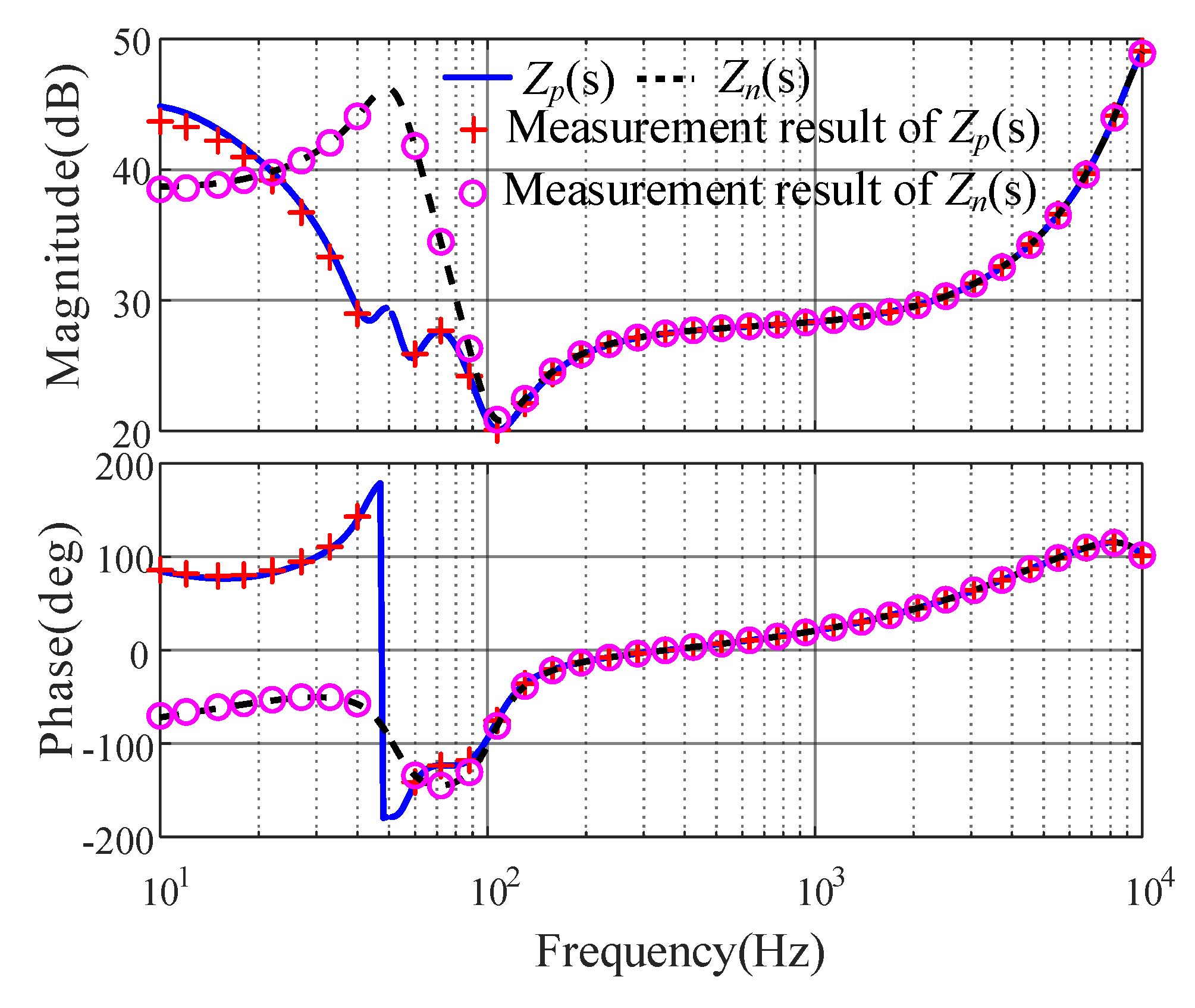
Table 1 shows the parameters of the grid-connected inverter. In order to verify the accuracy of the established inverter impedance model, at the impedance measurement simulation platform in Matlab/Simulink, it is assumed that the rated power of the inverter is 10 kW and is without a capacitive series-compensated system, and the grid-connected inverter operates stably. Figure 2 shows the impedance measurement results. As can be seen from Figure 2, the measurement results are very consistent with the established impedance model. The errors are minimal, which can explain the correctness of the established impedance model.

2.2. Effect of Parameters on Stability

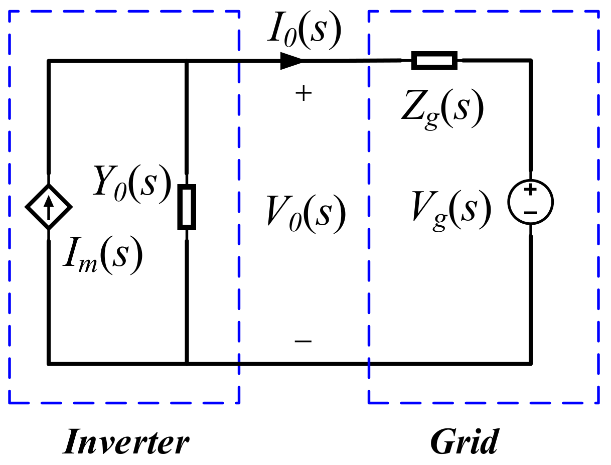
According to Figure 1, in an interconnected system of inverters and power grids, the grid-connected inverter can be regarded as the Norton equivalent circuit of the ideal current source Im(s) parallel output admittance Yo(s). The grid provides the grid-connected voltage reference for the inverter at the PCC. The grid can be regarded as the Thevenin equivalent circuit of the impedance Zg(s) cascade with the ideal voltage source Vg(s). The equivalent circuit of the grid-connected inverter system is shown in Figure 3.
The output current of the connected nodes of the two subsystems can be deduced as follows:
I 0 s = I m s Y 0 s V g s     1 1 + Y 0 s Z g s
The stable operation of the grid-connected inverter system is the primary condition for access to the grid. Therefore, the expression Im(s) − Y0(s)Vg(s) does not include the right half-plane poles. The stability of the output current and the voltage depends on the formula 1/[1 + Y0(s)Zg(s)]. According to the automatic control theory, as long as the loop gain Y0(s)Zg(s) of the closed-loop system without the right half-plane pole satisfies the Nyquist stability criterion, the inverter grid-connected system can maintain stability.
In order to analyze the stability of the system with different parameters, the impedance ratio of the SCGCS is established. Assuming that the grid is a completely symmetrical grid, Zpg(s) = Zng(s) = Zg(s) is the expression of the positive- and negative-sequence impedances of the grid. In order to analyze the stability of the system, the impedance ratio of the inverter and the grid is defined as follows:
G p s = Z g s / Z p s G n s = Z g s / Z n s
According to (19) and the definition of series compensation level ( S C L = 1 / ω n 2 L g C g ) [21], using different parameters, the Nyquist plots of (19) are shown in Figure 4.
As seen from Figure 4a, the Nyquist plots of Gp(s) and Gn(s) pass through the negative real axis to surround the point (−1, j0) from the right to the left when SCL increases from 25% to 50%. Therefore, the SCGCS gradually becomes unstable as the SCL increases. As the SCL gradually increases, the capacitive range of the grid impedance increases, which may lead to impedance interaction between the inverter impedance and the grid impedance. It can be seen from Figure 4b that when SCL = 25%, if the number of parallel inverters N gradually increases, the system gradually loses stability, and the Nyquist curves of Gp(s) and Gn(s) surround the point (−1, j0). From Figure 4, the increase in the number of parallel inverters and the increase in SCL will both make the stability of the SGCCS worse.
In order to further verify the correctness of the above analysis, according to the SGCCS shown in Figure 1, a simulation analysis was performed in MATLAB/Simulink, and the results are shown in Figure 5.
When the SCL increases from 0 to 50%, it can be seen from Figure 5 that the SCGCS changes from a stable state to a resonance state, and the grid-connected current igabc shows resonance.

3. Impedance-Based Resonance Suppression Method

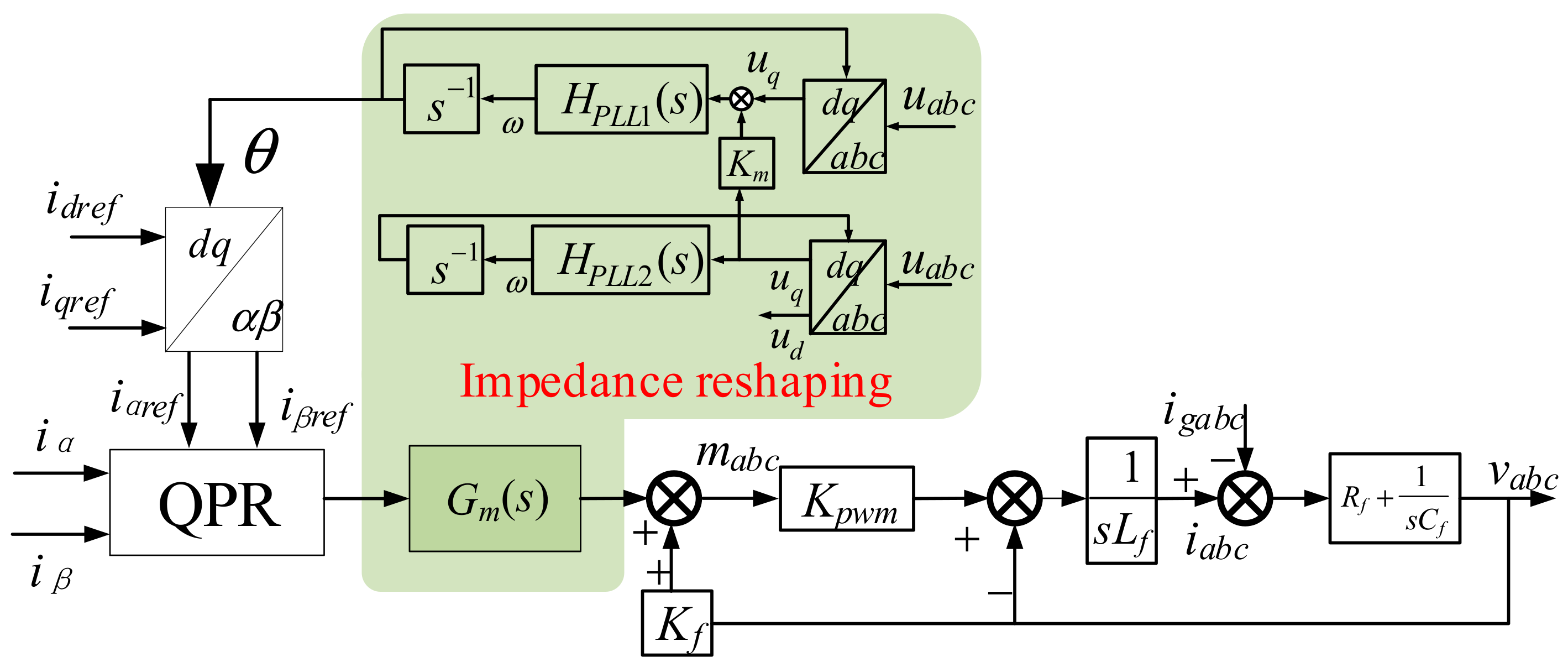
As shown in Figure 6, to mitigate the resonance between the inverter and the grid caused by the impedance interaction, an impedance-based resonance suppression method is proposed. The method is divided into two parts in reshaping the equivalent output impedance of the inverter. The first part is the impedance reshaping of the PLL, and the second part is the impedance reshaping of the current loop. A detailed analysis and design are as follows, where Kpwm is the modulator gain, mabc is the modulating signal, igabc is the current of the grid, and iabc is the output current of the inverter:

3.1. Phase-Locked Loop Impedance Reshaping

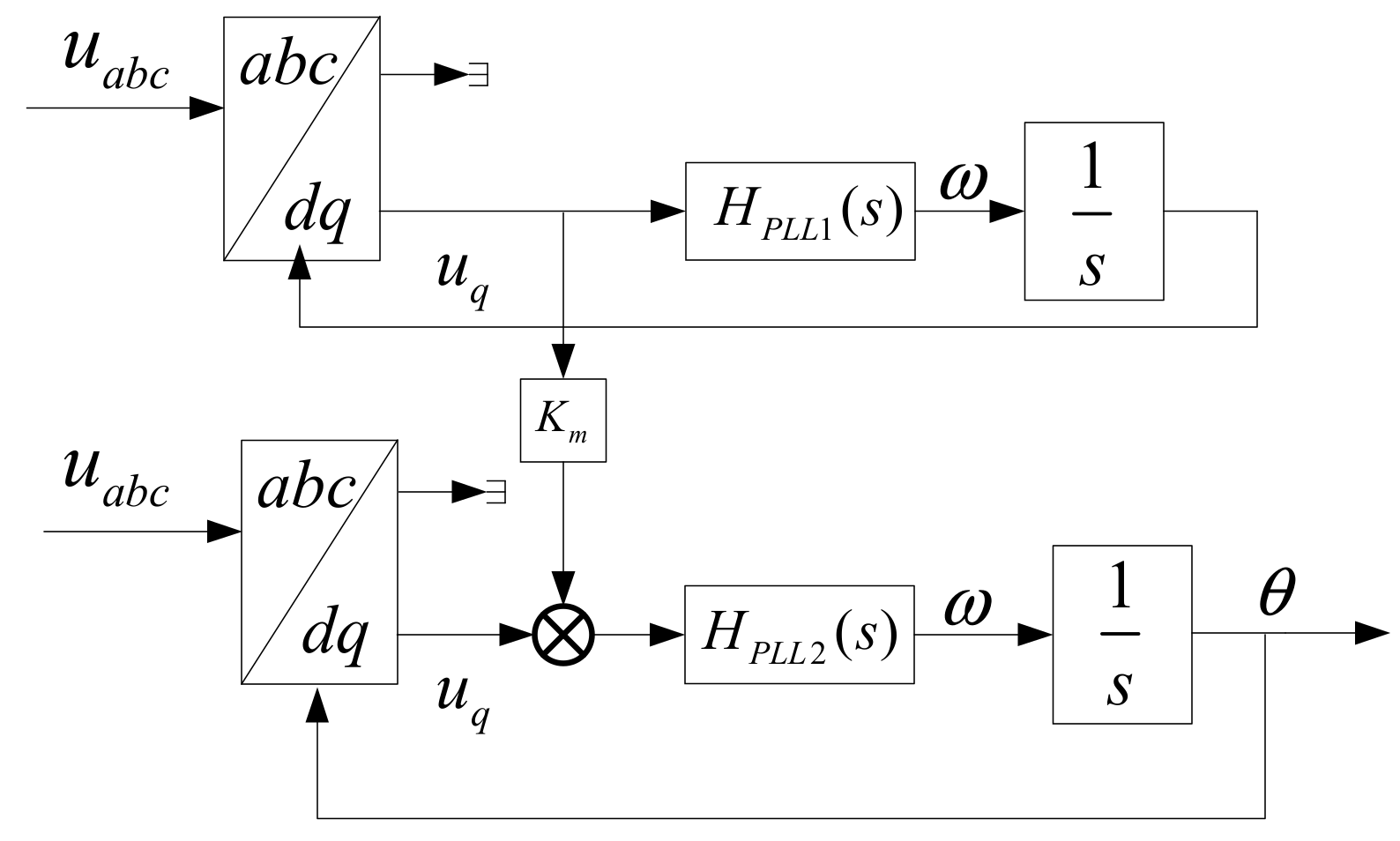
In the low frequency band, the equivalent additional impedance of the PLL is negative and will have an adverse effect on the stability of the system. In order to reduce the impact of the negative impedance on the stability of the system, an effective measure is to increase the PLL order to correct the phase-frequency characteristics of the additional impedance of the PLL. This paper proposes a cascaded phase-locked loop (CPLL) structure to reshape the impedance of the inverter. Figure 7 shows the control block diagram of the CPLL.
According to Figure 7, combined with the traditional SRF-PLL transfer function, the closed-loop transfer function of the CPLL can be obtained and is expressed as follows:
T P L * s = V 1 T P L s H P L L 2 s s + V 1 H P L L 2 s
where TPL(s) is the closed-loop transfer function of the traditional SRF-PLL.
After reshaping the impedance of the PLL, when the CPLL system control parameters are the same as the traditional SRF-PLL system parameters, Km = 0.8, the frequency characteristic curve of the positive sequence impedance of the inverter can be shown, as seen in Figure 8.
As seen in Figure 8, compared to the SRF-PLL, the inverter impedance amplitude is slightly increased. The phase difference between the inverter impedance and the grid impedance decreases obviously. The stability margin of the grid-connected inverter using CPLL is improved. Therefore, the stability of the grid-connected system is enhanced by using the CPLL.

3.2. Current Loop Impedance Reshaping

A phase compensation control method adds to the current loop to improve the phase margin of the system. This compensates for the lack of phase margin caused by the power grid weakening. The control block diagram is shown in Figure 9.
As seen from Figure 9, the phase compensation loop is in series with the current loop. It can be expressed as follows:
G m s = k s 1 + ξ 1 s 1 + ξ 1 ξ 2 s
where ks is the gain coefficient of the phase angle compensation, ξ1 is the phase angle coefficient of the phase angle compensation, and ξ2 is the proportional coefficient of the phase angle compensation. The expression of the phase frequency function of Gm(s) is:
φ m ω = arctan ξ 2 1 ξ 1 ω 1 + ξ 1 2 ξ 2 ω 2
Assuming that the angular frequency of the maximum compensation phase of φm(ω) is selected at fcw, we can get:
ξ 2 = 1 ξ 1 2 ( 2 π f c w ) 2
Assuming that the maximum compensation phase is ωc, combining Equations (22) and (23), the expression of ξ1 can be obtained as:
ξ 1 = tan ω c + 1 + tan ω c 2 2 π f c w
In this article, we use values fcw = 120 Hz and ωc = 45°, so that ξ1 = 0.0032 and ξ2 = 0.1719 can be calculated. In order to facilitate the attenuation of high-frequency harmonic components, the value of ks cannot be too large, but equally, if the value of ks is very small, it will lead to a decrease in the gain of the system at the fundamental wave frequency and increase the tracking error of the current. Therefore, ks needs be a compromise value. Based on the above analysis, ks = 0.4 is chosen in this paper. The positive-sequence impedance characteristic curve of the inverter when the SRF-PLL is used, before and after the current loop impedance reshaping, is shown in Figure 10.
As seen in Figure 10, after the current loop impedance reshaping, in the low-frequency region, the phase decreases, and the amplitude of the impedance remains the same. Therefore, due to the increase in the system phase angle margin, the stability of the grid-connected system is improved.
According to (12)–(17), (20), and (21), after adding the proposed two parts of impedance reshaping, the new impedance ratio can be expressed as follows:
G p c s = Z g s / Z p c s G n c s = Z g s / Z n c s
where Zpc(s) and Znc(s) are the positive-sequence and negative-sequence impedances of the inverter after impedance reshaping, respectively.
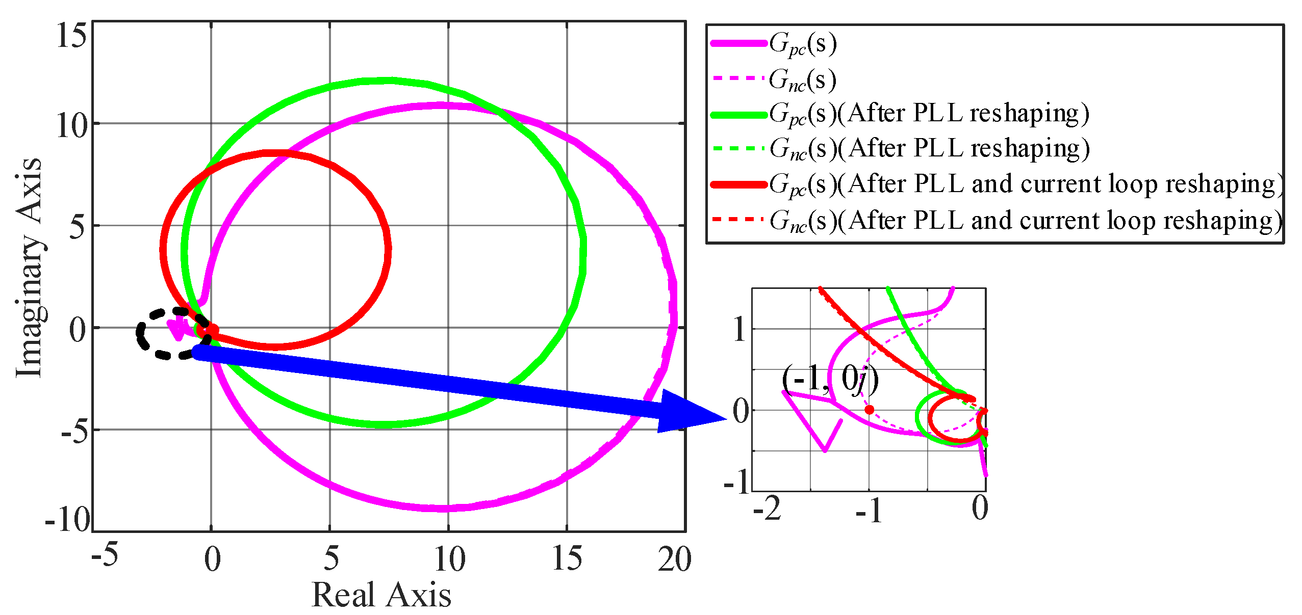
According to (25), the Nyquist plots of (25) after adding the impedance reshaping control are depicted in Figure 11 when the SCL = 50%.
As seen in Figure 11, after the impedance reshaping, the Nyquist plots of Gpc(s) and Gnc(s) do not encircle the (−1, j0) point. Therefore, when the SCL = 50%, by adding the impedance reshaping control strategy, the SCGCS changes from an unstable state to a stable state.
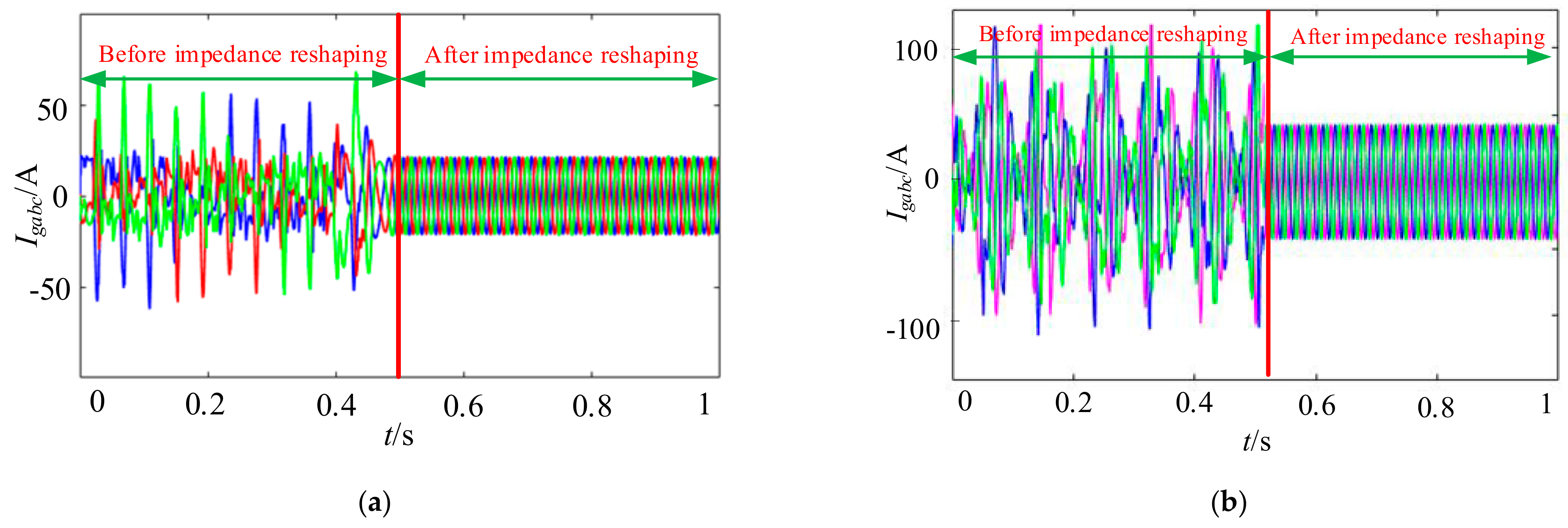
Aiming at the resonance phenomenon of the SCGCS in Figure 1, in order to prove the effectiveness of the proposed impedance reshaping control strategy in suppressing resonance, the simulation results obtained by MATLAB/Simulink when the SCL = 50% are shown as Figure 12.
As seen from Figure 12, When the power is 10 kW and 20 kW, with the proposed impedance reshaping control, the resonance can be effectively suppressed, and the SCGCS can maintain stability at last.

4. Experimental Results

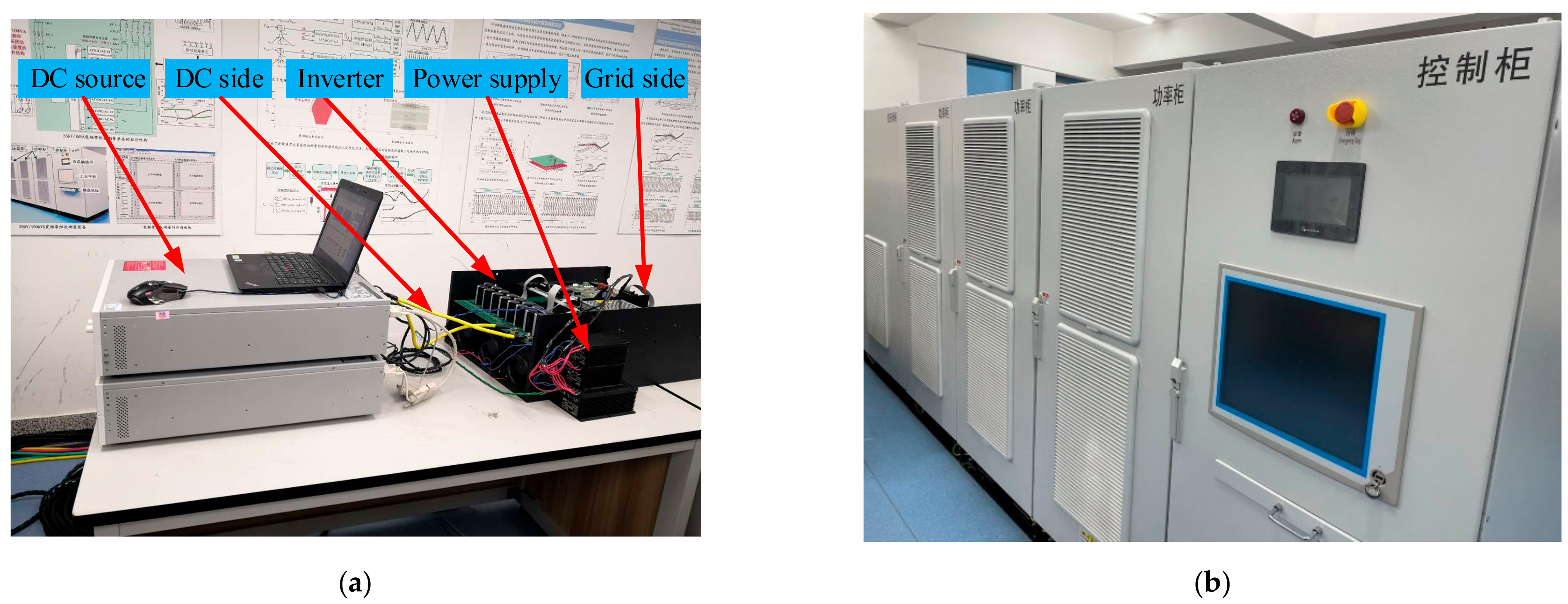
To verify the validity of the proposed method, the SCGCS and the impedance measurement equipment are built, as shown in Figure 13. The digital signal processor (DSP) + FPGA solution is selected as the control core of the system, and the execution of the control algorithm is realized by DSP TMS320F2812. Use EP2C8Q208CN to realize the field programmable gate array (FPGA) current and the voltage signal collection. The parameters of the circuit and controllers are given in Table 1. The experimental results are shown as follows:
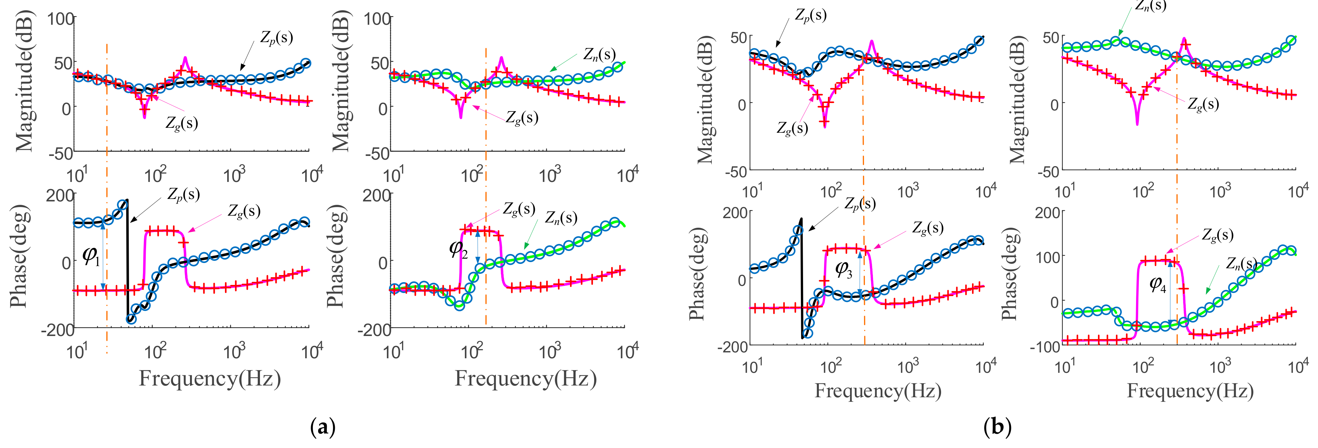
Experimental validation of the developed models is shown in Figure 14. Figure 14a,b show the positive-sequence impedance and the negative-sequence impedance of the SCGCS before and after the impedance reshaping, respectively. As can be seen from Figure 14, the measurement results are very consistent with the established impedance model as the errors are minimal. The impedance of the inverter after the impedance reshaping becomes more resistive below the fundamental frequency, and at the frequency where the amplitude curve intersects, the phase difference between the inverter impedance and the grid impedance becomes less than 180° (φ3,4 < 180° < φ1), which means that the system will change from an unstable state to a stable state.
In order to analyze the stability of the system when using different control methods under different SCL, four cases are selected as experimental verifications, as shown in Table 2.
Figure 15 shows the experimental waveforms with no impedance reshaping when SCL = 100%, the grid-connected system loses stability, the THD of the grid current is 281.14%, which results from the impedance interaction between the inverter and the grid.
Figure 16 shows the experimental waveforms with the impedance reshaping when SCL = 100%. As seen in Figure 16, after the impedance reshaping, the impedance of the power grid and the inverter does not meet the conditions of resonance generation. The resonance phenomenon disappeared, and the system is in a stable state.
Figure 17 shows the experimental waveforms with no impedance reshaping when SCL = 50%. The THD of the grid current is 135.72%. Compared with Figure 15, the THD of the grid current is decreased.
Figure 18 shows the experimental waveforms with the impedance reshaping when SCL = 50%. As seen in Figure 18, after the impedance reshaping, the resonance phenomenon disappeared. By using the proposed impedance shaping control strategy, the resonance caused by the interaction between the inverter impedance and the grid impedance is effectively suppressed. The above analysis results show that the experimental results are basically consistent with the theoretical analysis, and prove the effectiveness of the proposed resonance suppression strategy.

5. Conclusions

In order to solve the resonance problem caused by the impedance interaction between the inverter impedance and the grid impedance in the series compensation system, this paper proposes an impedance reshaping control strategy to suppress this resonance. The conclusions are shown as follows:
(1)
The SCGCS has similar power resonance problems as the traditional SG-based SCGCS. With the increase in SCL, power resonance will appear in the SCGCS. According to the established impedance model, the impedance of the inverter is inductive near the fundamental frequency. The impedance of the series-compensated network near fundamental frequency was capacitive, so it was prone to couple with the inverter, easily causing resonance. Additionally, with the increase in the SCL and the number of parallel inverters, the stability of the SCGCS worsens.
(2)
In order to suppress the power resonance of the SCGCS, an impedance reshaping control strategy is proposed and verified with experiments. The amplitude–frequency characteristics of the inverter impedance are changed through the PLL and the current loop impedance shaping. After the impedance reshaping, the SCGCS can maintain a sufficient phase margin, and the stable operation of the SCGCS is guaranteed.
(3)
The proposed impedance shaping control can be easily applied to other controllers to achieve a good resonance suppression effect, and no additional resonance suppression equipment is needed, which reduces equipment investment and power loss.

Author Contributions

H.W. and Y.C. provided the original idea for this paper. H.W., W.W., S.L., Z.W., G.L., Z.X., and J.G. organized the manuscript and attended the discussions when analysis and verification were carried out. All the authors gave comments and suggestions on the writing and descriptions of the manuscript. All authors have read and agreed to the published version of the manuscript.

Funding

National Key Research and Development Program: 2017YFB0902000, The National Natural Science Foundation of China: 52077070, The China Postdoctoral Science Foundation under Grant: 2020M682551, The Postdoctoral Innovative Talent Support Program of China under Grant: BX20190109.

Institutional Review Board Statement

Not applicable.

Informed Consent Statement

Not applicable.

Data Availability Statement

The data presented in this study are available on request from the corresponding author.

Conflicts of Interest

The authors declare no conflict of interest.

References

  1. Pyrgou, A.; Kylili, A.; Fokaides, P.A. The future of the Feed-in Tariff (FiT) scheme in Europe: The case of photovoltaics. Energy Policy 2016, 95, 94–102. [Google Scholar] [CrossRef]
  2. Clastres, C. Smart grids: Another step towards competition, energy security and climate change objectives. Energy Policy 2011, 39, 5399–5408. [Google Scholar] [CrossRef] [Green Version]
  3. Xie, X.; Liu, W.; Liu, H.; Du, Y.; Li, Y. A System-Wide Protection Against Unstable SSCI in Series-Compensated Wind Power Systems. IEEE Trans. Power Deliv. 2018, 33, 3095–3104. [Google Scholar] [CrossRef]
  4. Karunanayake, C.; Ravishankar, J.; Dong, Z.Y. Nonlinear SSR Damping Controller for DFIG Based Wind Generators Interfaced to Series Compensated Transmission Systems. IEEE Trans. Power Syst. 2020, 35, 1156–1165. [Google Scholar] [CrossRef]
  5. Li, G.; Chen, Y.; Luo, A.; Wang, H. An Enhancing Grid Stiffness Control Strategy of STATCOM/BESS for Damping Sub-Synchronous Resonance in Wind Farm Connected to Weak Grid. IEEE Trans. Ind. Inform. 2019, 16, 5835–5845. [Google Scholar] [CrossRef]
  6. Sun, J.; Li, M.; Zhang, Z.; Xu, T.; He, J.; Wang, H.; Li, G. State Grid Corporation of China; China Electric Power Research Institute Renewable energy transmission by HVDC across the continent: System challenges and opportunities. CSEE J. Power Energy Syst. 2017, 3, 353–364. [Google Scholar] [CrossRef]
  7. Sun, J. Small-Signal Methods for AC Distributed Power Systems—A Review. IEEE Trans. Power Electron. 2009, 24, 2545–2554. [Google Scholar]
  8. Miao, Z. Impedance-Model-Based SSR Analysis for Type 3 Wind Generator and Series-Compensated Network. IEEE Trans. Energy Convers. 2012, 27, 984–991. [Google Scholar] [CrossRef]
  9. Wen, B.; Boroyevich, D.; Burgos, R.; Mattavelli, P.; Shen, Z. Analysis of D-Q Small-Signal Impedance of Grid-Tied Inverters. IEEE Trans. Power Electron. 2016, 31, 675–687. [Google Scholar] [CrossRef]
  10. Fu, S.; Zhang, X.; Xu, D. Improved control method of grid-connected converter based on voltage perturbation compensation under weak grid conditions. In Proceedings of the 10th International Conference on Power Electronics and ECCE Asia (ICPE 2019—ECCE Asia), Busan, Korea, 27–30 May 2019; pp. 1–6. [Google Scholar]
  11. Shuai, Z.; Li, Y.; Wu, W.; Tu, C.; Luo, A.; Shen, J.Z. Divided DQ Small-Signal Model: A New Perspective for the Stability Analysis of Three-Phase Grid-Tied Inverters. IEEE Trans. Ind. Electron. 2019, 66, 6493–6504. [Google Scholar] [CrossRef]
  12. Cespedes, M.; Sun, J. Impedance Modeling and Analysis of Grid-Connected Voltage-Source Converters. IEEE Trans. Power Electron. 2014, 29, 1254–1261. [Google Scholar] [CrossRef]
  13. Rygg, A.; Molinas, M.; Zhang, C.; Cai, X. A Modified Sequence-Domain Impedance Definition and Its Equivalence to the dq-Domain Impedance Definition for the Stability Analysis of AC Power Electronic Systems. IEEE J. Emerg. Sel. Top. Power Electron. 2016, 4, 1383–1396. [Google Scholar] [CrossRef] [Green Version]
  14. Sadamoto, T.; Chakrabortty, A.; Ishizaki, T.; Imura, J.-I. Retrofit Control of Wind-Integrated Power Systems. IEEE Trans. Power Syst. 2017, 33, 2804–2815. [Google Scholar] [CrossRef]
  15. Moharana, A.; Varma, R.K.; Seethapathy, R. SSR Alleviation by STATCOM in Induction-Generator-Based Wind Farm Connected to Series Compensated Line. IEEE Trans. Sustain. Energy 2014, 5, 947–957. [Google Scholar] [CrossRef]
  16. Wang, L.; Truong, D.-N. Stability Enhancement of a Power System with a PMSG-Based and a DFIG-Based Offshore Wind Farm Using a SVC with an Adaptive-Network-Based Fuzzy Inference System. IEEE Trans. Ind. Electron. 2012, 60, 2799–2807. [Google Scholar] [CrossRef]
  17. Fan, L.; Miao, Z. Mitigating SSR Using DFIG-Based Wind Generation. IEEE Trans. Sustain. Energy 2012, 3, 349–358. [Google Scholar] [CrossRef]
  18. Wu, W.; Chen, Y.; Luo, A.; Zhou, L.; Zhou, X.; Yang, L.; Dong, Y.; Guerrero, J.M. A Virtual Inertia Control Strategy for DC Microgrids Analogized with Virtual Synchronous Machines. IEEE Trans. Ind. Electron. 2017, 64, 6005–6016. [Google Scholar] [CrossRef] [Green Version]
  19. Mohammadpour, H.A.; Santi, E. SSR Damping Controller Design and Optimal Placement in Rotor-Side and Grid-Side Converters of Series-Compensated DFIG-Based Wind Farm. IEEE Trans. Sustain. Energy 2015, 6, 388–399. [Google Scholar] [CrossRef]
  20. Huang, P.-H.; El Moursi, M.S.; Xiao, W.; Kirtley, J.L. Subsynchronous Resonance Mitigation for Series-Compensated DFIG-Based Wind Farm by Using Two-Degree-of-Freedom Control Strategy. IEEE Trans. Power Syst. 2014, 30, 1442–1454. [Google Scholar] [CrossRef]
  21. Li, G.; Chen, Y.; Luo, A.; He, Z.; Wang, H.; Zhu, Z.; Wu, W.; Zhou, L. Analysis and Mitigation of Subsynchronous Resonance in Series-Compensated Grid-Connected System Controlled by a Virtual Synchronous Generator. IEEE Trans. Power Electron. 2020, 35, 11096–11107. [Google Scholar] [CrossRef]
  22. Xie, Z.; Wu, W.; Chen, Y.; Gong, W. Admittance-Based Stability Comparative Analysis of Grid-Connected Inverters with Direct Power Control and Closed-Loop Current Control. IEEE Trans. Ind. Electron. 2021. [Google Scholar] [CrossRef]
  23. Wang, X.; Blaabjerg, F. Harmonic Stability in Power Electronic-Based Power Systems: Concept, Modeling, and Analysis. IEEE Trans. Smart Grid 2019, 10, 2858–2870. [Google Scholar] [CrossRef] [Green Version]
  24. Zhang, C.; Cai, X.; Rygg, A.; Molinas, M. Sequence Domain SISO Equivalent Models of a Grid-Tied Voltage Source Converter System for Small-Signal Stability Analysis. IEEE Trans. Energy Convers. 2017, 33, 741–749. [Google Scholar] [CrossRef]
Figure 1. Configuration and control structure of the SCGCS.
Energies 14 02844 g001
Figure 2. Sequence impedance of the grid-connected inverter.
Energies 14 02844 g002
Figure 3. Equivalent circuit of the SCGCS.
Energies 14 02844 g003
Figure 4. Nyquist Plots of (19), (a). Different SCL, (b) different number N of parallel inverter.
Energies 14 02844 g004
Figure 5. Simulation results with different SCL. (a) Grid-connected current waveform, (b) spectrum of the current when SCL = 50%.
Energies 14 02844 g005
Figure 6. Proposed resonance suppression method based on impedance reshaping.
Energies 14 02844 g006
Figure 7. Control block diagram of the CPLL.
Energies 14 02844 g007
Figure 8. Impedance characteristic curve of the inverter after PLL impedance reshaping.
Energies 14 02844 g008
Figure 9. Proposed current loop impedance reshaping control strategy.
Energies 14 02844 g009
Figure 10. Impedance characteristic curve of the inverter after the current loop impedance reshaping.
Energies 14 02844 g010
Figure 11. Nyquist Plots of (25) after adding the impedance reshaping.
Energies 14 02844 g011
Figure 12. The grid-connected current waveform after the impedance reshaping. (a) P = 10 kW. (b) P = 20 kW.
Energies 14 02844 g012
Figure 13. Experimental platform. (a) The SCGCS, (b) impedance measurement equipment.
Energies 14 02844 g013
Figure 14. Experimental results of the impedance measurement (a). Before impedance reshaping control, (b) after the impedance reshaping control.
Energies 14 02844 g014
Figure 15. Experiment results with no impedance reshaping control strategy when SCL = 100%. (a) Grid current, (b) PCC voltage, (c) active and reactive power.
Energies 14 02844 g015
Figure 16. Experiment results with the impedance reshaping control strategy when SCL = 100%. (a) Grid current, (b) PCC voltage, (c) active and reactive power.
Energies 14 02844 g016
Figure 17. Experiment results with no impedance reshaping control strategy when SCL = 50%. (a) Grid current, (b) PCC voltage, (c) active and reactive power.
Energies 14 02844 g017
Figure 18. Experiment results with the impedance reshaping control strategy when SCL = 50%. (a) Grid current, (b) PCC voltage, (c) active and reactive power.
Energies 14 02844 g018
Table 1. Parameters of the grid-connected inverter.
Parameters/UnitValueParameters/UnitValue
Lf (mH)3Cg (F)0.0013
Cf (μF)22ωc (rad/s)5
Rf (Ω)2.87ωg (rad/s)100π
kp_PLL0.2659Lg (mH)15
ki_PLL10.9988Rg (Ω)0.2
kp3Kf1/350
kr4vdc (V)700
V1 (V)311Tv (μs)50
I1 (A)21.43Ti (μs)50
f1 (Hz)50fs (kHz)10
Table 2. Four cases under different control methods.
CaseImplementation Form
Case AWithout the impedance reshaping when SCL = 100%
Case BWith the impedance reshaping when SCL = 100%
Case CWithout the impedance reshaping when SCL = 50%
Case DWith the impedance reshaping when SCL = 50%
Publisher’s Note: MDPI stays neutral with regard to jurisdictional claims in published maps and institutional affiliations.