Article

Real-Time Sensing Action of the Electromagnetic Vibration-Based Energy Harvester for a Magnetorheological Damper Control

Department of Process Control, Faculty of Mechanical Engineering and Robotics, AGH University of Science and Technology, Mickiewicza 30 av., 30-059 Krakow, Poland
*
Author to whom correspondence should be addressed.
Energies 2021, 14(10), 2845; https://doi.org/10.3390/en14102845
Submission received: 13 April 2021 / Revised: 30 April 2021 / Accepted: 11 May 2021 / Published: 14 May 2021
(This article belongs to the Special Issue Automation and Robotics Application in Energy Systems)

Abstract

:
This study investigated the self-sensing mechanism in the electromagnetic vibration-based energy harvester (EV-EH) prototype specially engineered for a commercial magnetorheological (MR) damper. The objective of the work is to demonstrate that the EV-EH unit with a specific self-powered feature can also be employed as a relative velocity sensor in the system. To do this, the self-sensing action of the unit was experimentally studied over the assumed range of working conditions. The analysis of the test results and the determined self-sensing function indicated that the EV-EH has a highly accurate monitoring capability. The EV-EH self-sensing and self-powered features confirm the potentials and applicability of the unit for MR damper control in a vibration reduction system with energy regeneration.

1. Introduction

In recent years, much research has been conducted on energy harvesting MR dampers. The purpose of energy harvesting is to employ mechanical energy resulting from vibrations and shocks into a power supply. Most widely used in this field is a mechanical-electrical energy converting system using electromagnetic induction. The advantage of energy harvesting MR dampers is that they are able to recover energy from external vibrations and shocks and to adjust themself to excitations by varying the damping characteristics. In such dampers, two categories of energy harvesting are applied. The first one is based on an electromagnetic induction device that generates power from the relative motion between magnets and coils (Cho et al. [1], Choi et al. [2], Sapiński [3]), and the second is to convert linear damper vibration into the oscillatory rotation and use rotational permanent magnetic DC or AC generators to harvest energy (Zhang et al. [4], Yu et al. [5], Chu et al. [6]).
A great deal of research has been focused on the possibility of achieving self-powered capabilities of MR dampers, the components of which may be engineered either as separate elements and then mounted in the system or integrated into standalone devices. Less attention has been given to achieving the self-sensing capability of these devices. This feature, however, seems to be important, particularly when considering MR damper control in the system. The best use of the MR damper characteristics requires feeding back its dynamic response to the system controller. For this purpose, in real-time control applications, sensors such as accelerometers and vibrometers are employed. However, the relative velocity sensor is difficult to integrate into the MR damper.
The self-sensing capability of MR dampers has been investigated by using various configurations of the EV-EH, which employs Faraday’s law arising from the relative motion of the magnetic flux gradient and a conductor. The alternating current can indicate the direction of MR damper movement, and because the change in electromotive force ( e m f ) caused by the change in time rate is proportional to the relative velocity, the e m f can easily be used to represent the relative velocity across the damper piston.
In the last decade, the sensing capability of MR dampers had been found in several studies. For example, the feasibility and efficiency of a self-powered MR damper using a spring-mass electromagnetic energy harvester was studied by Choi and Werely [7]. Jung et al. [8] showed that an electromagnetic energy harvester incorporated in the MR damper-based system might act as a velocity-sign sensor. Also, Jung et al. [9] demonstrated that such harvester could act as a relative velocity sensor in typical control strategies for MR damper-based systems. An integrated relative displacement self-sensing MR damper to realise the integrated relative displacement sensing and controllable damping was proposed by Wang et al. [10]. Next Wang and Bai [11] formulated this concept and fabricated such an MR damper prototype. The idea of superposes the information of the damper’s motion to the e m f signal, which can be further modulated via the feedback strategy was developed by Peng et al. [12]. Chen and Liao [13] investigated MR damper prototype with self-powered and self-sensing capabilities. Similarly, Rosół and Sapiński [14] investigated the engineered MR damper prototype integrated into a standalone device with self-sensing capabilities and demonstrated its potential to act as a velocity sensor. The self-powered and sensor-based MR damper systems, which could be particularly useful in large-scale civil structures where the power supply is impractical was studied by Zhu et al. [15]. An innovative concept of a so-called mechanical motion rectifier that converts bidirectional motion into unidirectional motion was presented by Li et al. [16]. Also Li et al. [17] developed a retrofittable design of a shock absorber based on permanent magnets and rack-pinion mechanism. Ni et al. [18] presented and identified inverse dynamics of a self-sensing MR damper that may be used in a reduction control systems. Chen et al. [19] demonstrated reliable force for sensing and controllable damping capabilities of a MR damper with a piezoelectric force sensor. Hu et. al. [20] evaluated static and dynamic behaviour of a MR damper with a self-induced capability integrated with a linear variable differential sensor-based. Also, Hu et al. [21] proposed a self-sensing MR damper with an electromagnetic harvester with controllable damping capability. Xinchun et al. [22] presented the MR damper equipped with a vibration energy harvesting mechanism based on a DC generator, ball-screw and rotary of a permanent magnet indicated the self-powered capability of this configuration. Guan et al. [23] demonstrated high accuracy monitoring capability of the MR damper with a novel velocity self-sensing mechanism.
The present study deals with a system compound of the engineered EV-EH that generates power from the relative motion between magnet and coil, and a commercial mono-tube MR damper with a short stroke range. The objective of the research was to demonstrate that the EV-EH can act as a velocity sensor (self-sensing capability) and is able to control the MR damper using energy harvested from vibrations (self-powered capability).
The work is organised in the following manner. Section 2 and Section 3 present the structure of the EV-EH and the MR damper. Section 4 investigates the self-sensing function and self-powered capability and discusses the obtained results. Section 5 describes the implementation and testing of self-sensing and self-powered actions to demonstrate their applicability for MR damper control. Final conclusions are provided in Section 6.

2. Electromagnetic Vibration-Based Energy Harvester

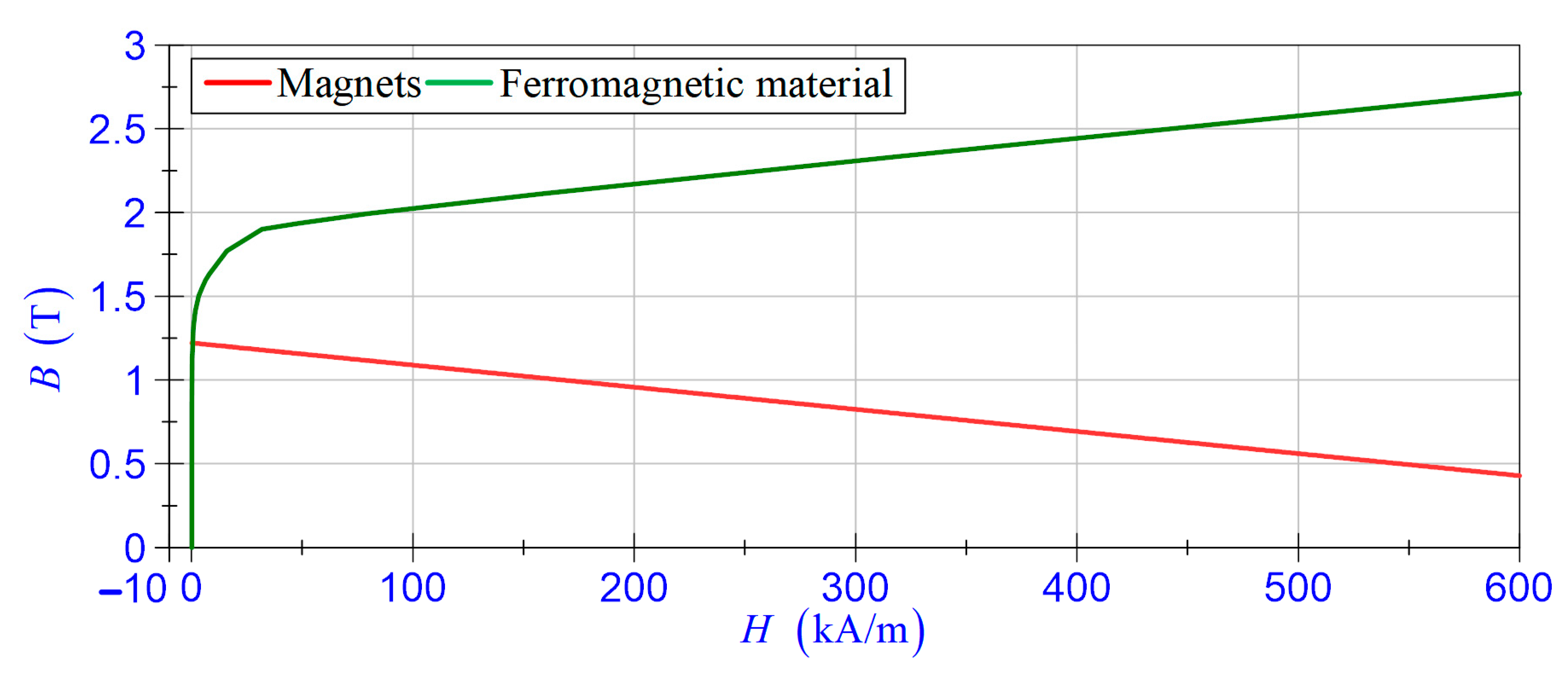
The structure of the EV-EH with the dimensions of its structural components are shown in Figure 1. The unit is symmetrical and features a non-magnetic rod with two sets of six radially magnetised neodymium magnets and a coil placed inside a housing, which acts as a shield against magnetic disturbances. The magnet assemblies are faced with each other and separated by a ring. Inside the housing, there is a carcass on which the foil winding (260 turns) is made of the one-side insulated coil. The details of EV-EH components are described in [24]. According to Faraday’s law, the EV-EH produces electrical energy from the relative motion of magnets against the coil. The e m f induced in the coil is linked to the product of the velocity and the flux linkage gradient, which is dependent on the applied magnets to produce the field, the arrangement of the magnets, the area, and the number of turns of the coil. The magnetic characteristics B ( H ) of the magnets and ferromagnetic material used are provided in Figure 2. The measured resistance and the inductance of the EV-EH coil are R h = 0.25   Ω and L h = 4.78   mH , the electric constant is 18.5   Vs / m .

3. Magnetorheological Damper

The structure of the MR damper is shown in Figure 3. This is a typical mono-tube range MR damper (RD-8040-1 short-stroke series of Lord Corporation) [25] with is suitable for most development applications. The annular flow path in the piston assembly and the chamber is filled with MR fluid. In the lower part of the chamber, there is a diaphragm separating MR fluid from the gas-charged accumulator. The control coil is wrapped around a piston core. The damper force is controlled by the magnetic field induced via input current in the control coil. The key mechanical and electrical properties of the damper are as follows: stroke 55   mm , min. force < 667   N (for 20   mm / s and 0   A ), max. force > 2447   N (for 50   mm / s and 1   A ), input current (continuous for 30   s ) – max. 1   A , (intermittent) 2   A max., supply voltage 12   V DC. The measured resistance of the control coil is R d = 5.5   Ω and the inductance L d = 125   mH [26].

4. Experimental Tests and Analysis of Self-Sensing and Self-Powered Capability

4.1. Test Rig and Measurement System

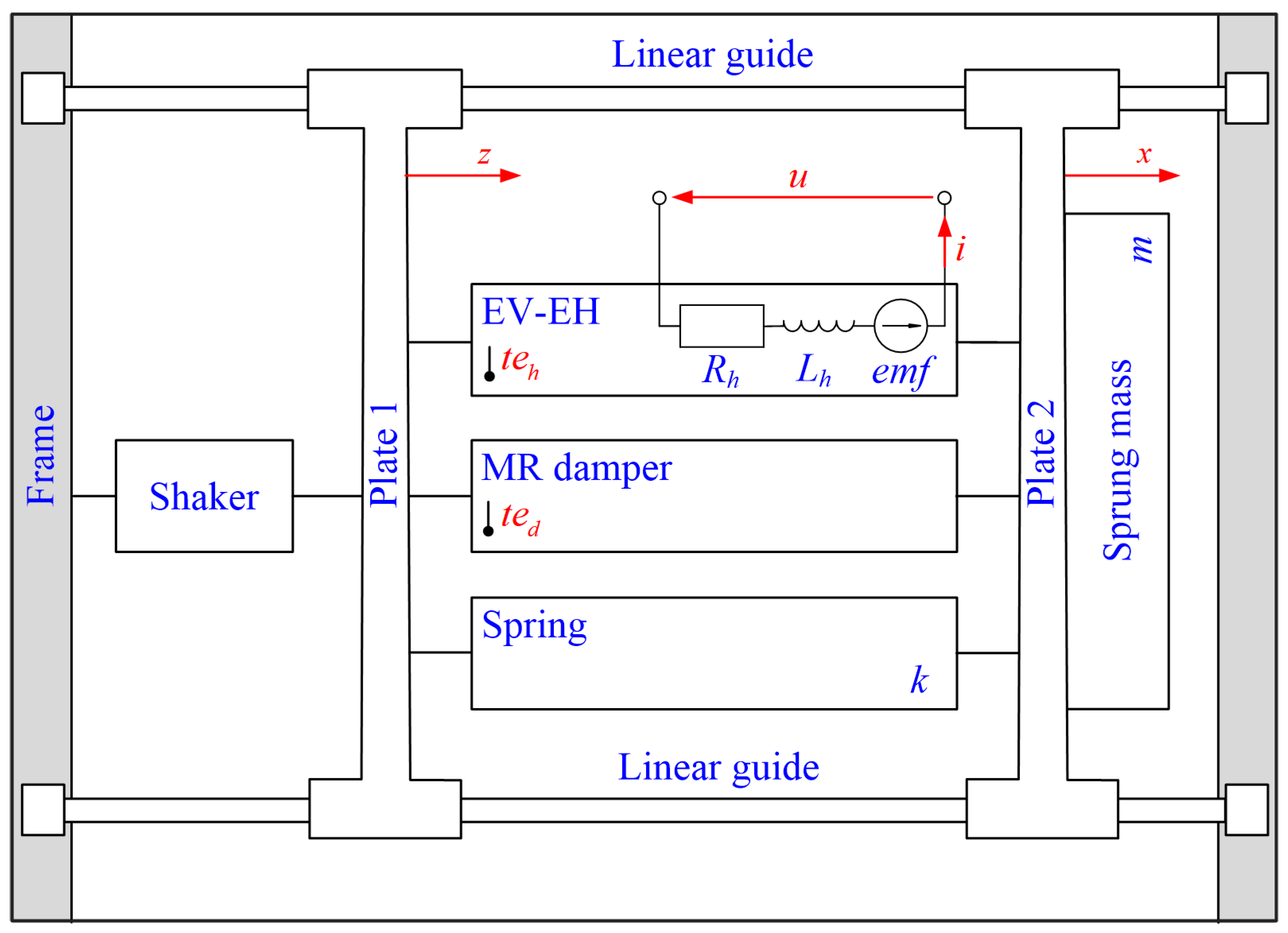
The aim of the research was to demonstrate that the EV-EH exhibited self-sensing and self-powered capabilities and can be applied to control an MR damper in a vibration reduction system. The tests were conducted in a test rig equipped with the electrodynamic shaker LDS V780 [27]. The test rig (see Figure 4) consisted of a steel frame and plates 1 and 2, which could move horizontally on linear guides. The EV-EH, the MR damper, and the spring are installed in parallel between plate 1 and plate 2. The sprung mass was m = 150   kg and the spring stiffness coefficient was k = 10 5   N / m . Such selection of m and k parameters allow for compensating the MR damper diaphragm stiffness. This is important for the correct operation of EV-EH. The geometrical structure of EV-EH is designed to ensure linear operation in the range of ± 12   mm . The parameters defining the structure of the remaining elements of the test rig were selected so that in the standby mode, the EV-EH ring was in the middle position in relation to the coil, and in the operating mode, the displacement of the magnets in relation to the coil was within a defined range.
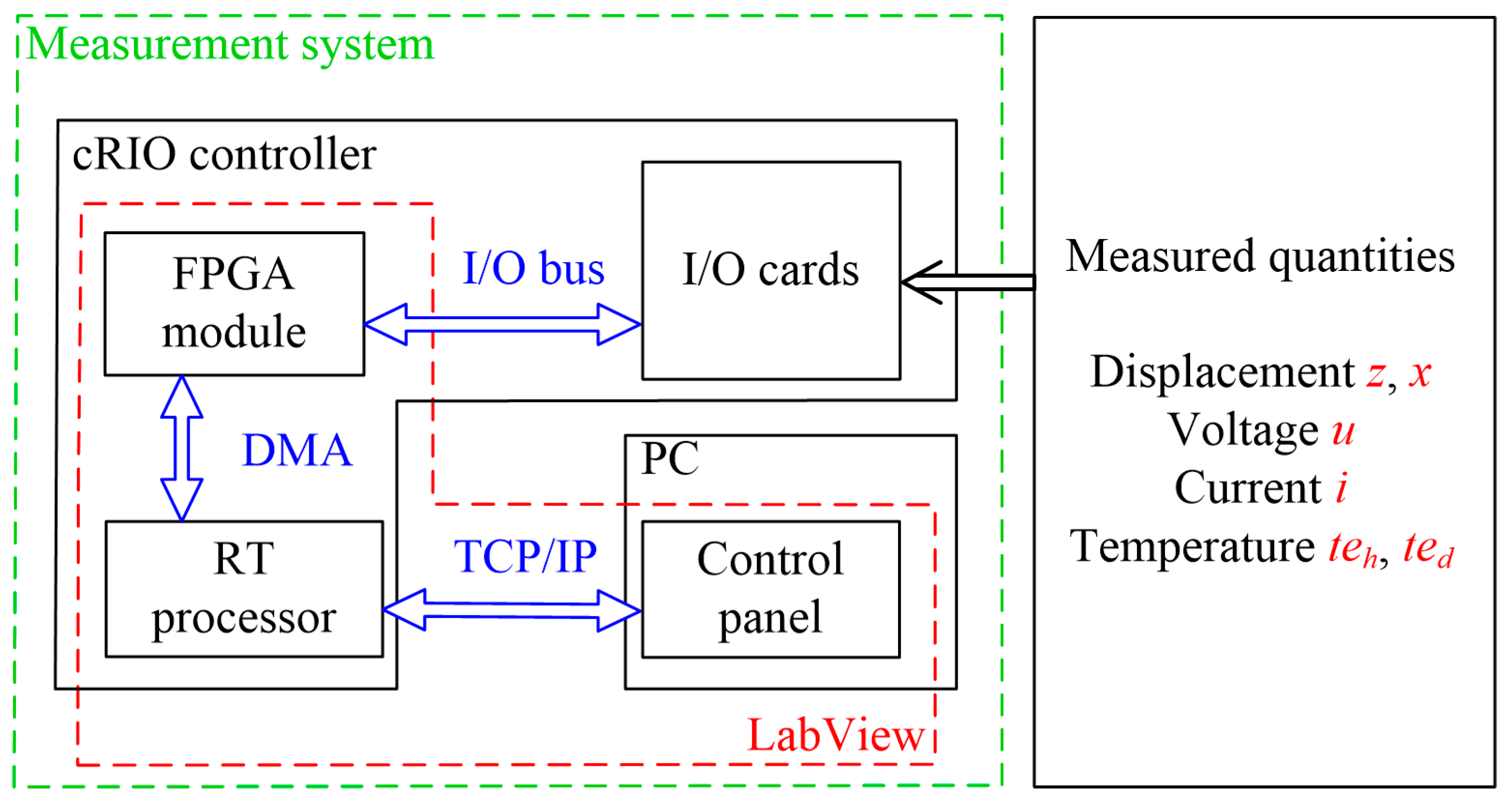
The measurement system dedicated to the test rig consisted of a cRIO 9063 [28] controller, a personal computer, a set of transducers, and measurement cards (see Figure 5). The application layer of the system was developed in the LabView environment, taking into account the hardware architecture of the cRIO controller. The controller included a real-time processor (RT-Linux environment) and a module of field programmable gate array (FPGA). The FPGA module was used for operating the measurement cards (I/O bus), calculating z ˙ and x ˙ velocities, buffering, and sending the measurement data to the RT processor (DMA channel). The data sent by the FPGA module were scaled and stored on an external SSD disk. The RT processor was also responsible for the data exchange (TCP/IP protocol) with a control panel application implemented on an external PC.
The measurement system allowed for measuring the following values: excitation generated by the shaker z (kinematic displacement), sprung mass displacement x , voltage and current in the EV-EH coil u , i , and temperature on the surface of the EV-EH housing and the MR damper t e h , t e d . The displacements z and x were determined using two linear incremental encoders SME54-YC-2-PROG-R-L2 [29] and an NI-9401 fast digital input card ( 10   MHz ). The instantaneous value of current i was measured using a current-to-voltage converter containing a current sense resistor ( 0.01   Ω ), operational amplifiers (AD629 and AD8622), and an NI-9215 measurement card. This card was also used to measure the instantaneous value of voltage u . The instantaneous value of temperatures t e h and t e d were measured using type K thermocouples and an NI-9211 card.

4.2. Data Acquisition

The data were acquired at a sinusoidal excitation z with amplitude A z = 3.5   mm and frequency f z varied in the ( 2 , 10 )   Hz range for nine cases (see Figure 6):
  • Case C 1 —idle run (the EV-EH coil was disconnected);
  • Cases C 21 , C 22 , C 23 , C 24 —under load R a : 1   Ω , 2.5   Ω , 5   Ω in t e h ( 0 ) = 23.7   ,   5   Ω in t e h ( 0 ) = 21.4   (the maximum value of R a was nearly equal to R d , the minimum value was chosen so that voltage u generated by the EV-EH did not exceed the measured range of the NI 9215 card);
  • Case C 31 —under load R b L b ( R b = 5.2   Ω , L b = 100   mH ) and C 32 ( R b = 5.2   Ω , L b = 200   mH ) ;
  • Cases C 41 , C 42 —under load R d L d in t e d ( 0 ) = 21.4   for C 41 and t e d ( 0 ) = 28.8   for C 42 .
The measured quantities were recorded with a sampling frequency of 10   kHz , and the MR damper was only connected to the source of power in cases C 41 and C 42 . Considering the designations, the standard deviation value   σ for each registered quantity was equal: σ z ˙ = 1.17   mm / s , σ x ˙ = 0.25   mm / s , σ u = 0.021   V and σ i = 0.015   A . The calculations were performed with the excitation system in on-state and the set value z = 0   mm . The acquired data enabled us to analyse displacement transmissibility in the system, to determine the self-sensing function and to investigate the self-powered capability.

4.3. Data Analysis

4.3.1. Displacement Transmissibility

Assuming that A x is the amplitude of the sprung mass displacement and A z and f z are the amplitude and frequency of the excitation z , the displacement transmissibility coefficient of the system can be expressed as:
T x z ( f z ) = A x ( f z ) A z ( f z )
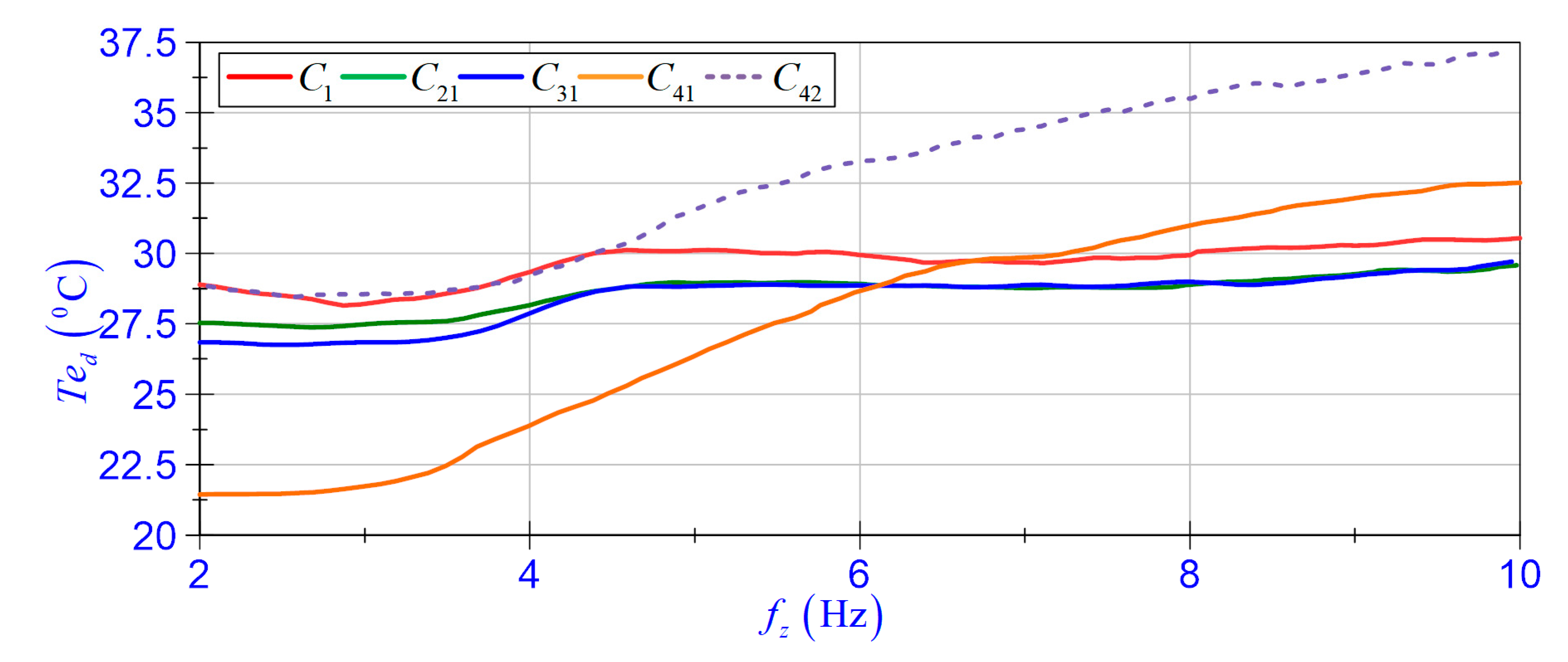
Figure 7 presents the T x z ( f z ) plots for cases C 1 , C 21 , C 31 , C 41   and C 42 . As can be observed, the value T x z depends on the current level in the EV-EH coil circuit. One can also observe the boundary frequency f b = 4.82   Hz , below which the energy supplied to the MR damper control coil decreased the sprung mass vibration amplitude. At frequencies higher than f b , the MR damper control coil should be disconnected from the EV-EH coil and replaced by an energy storage unit. Additionally, the plots in Figure 8 present the relationship of the average MR damper housing temperature T h d in a function of frequency f z ( T h d = mean (   t e d ) ), indicating that in the ( 20 , 29 )   range, the temperature does not have a significant impact on the T x z coefficient value (cases C 41 and C 42 ). In a wider range, a possible impact of temperature on the T x z coefficient value can be adjusted using a temperature-sensitive controller, as shown by Batterbee et al. [30].

4.3.2. Self-Sensing Function

The procedure of determination of the self-sensing function consisted of six steps. In step one, moving mean filtration with a fixed window width of 40 samples was used to process data of relative velocity v r = x ˙ z ˙ , voltage u , and current i . The velocity x ˙ and z ˙ were determined as a quotient of constant displacement 1   μ m and the time-lapse was measured by a clock with 40   MHz oscillator. In step two, the time shift Δ t between velocity v r and voltage u was calculated using the cross-correlation function. In step three, the time shift correction of voltage u and current i data were determined (the quantities accounting for the Δ t correction calculated in step two are denoted u t   and i t ). In step four, the velocity self-sensing function v u according to Equation (2) was identified:
v u = a · u t + b
Taking into account the relative velocity v r as a reference, the values of gain a and offset b were calculated using the singular value decomposition method. In step five, the relationship between gain a and frequency f u , resulting from the change of voltage u for cases C 1 C 42 , was determined. In step six, the linear correlation coefficient r (known as Pearson’s correlation) between v u and v r was calculated.
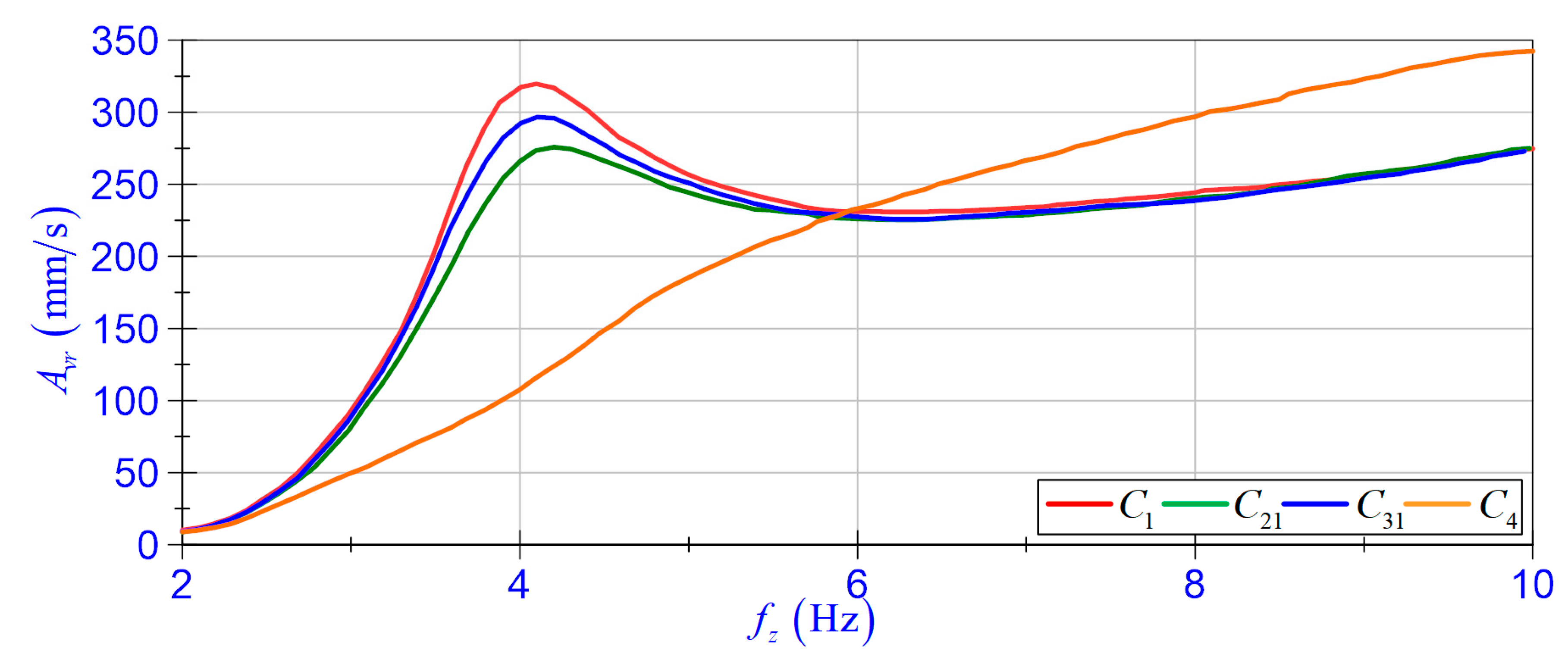
The self-sensing function was determined in the frequency range of relative velocity v r achievable on the test rig. The v r was a sinusoidally variable value with amplitude A v r . Figure 9 shows the relationship A v r ( f z ) , considering the limitation for the amplitude value A z as a function of frequency f z .
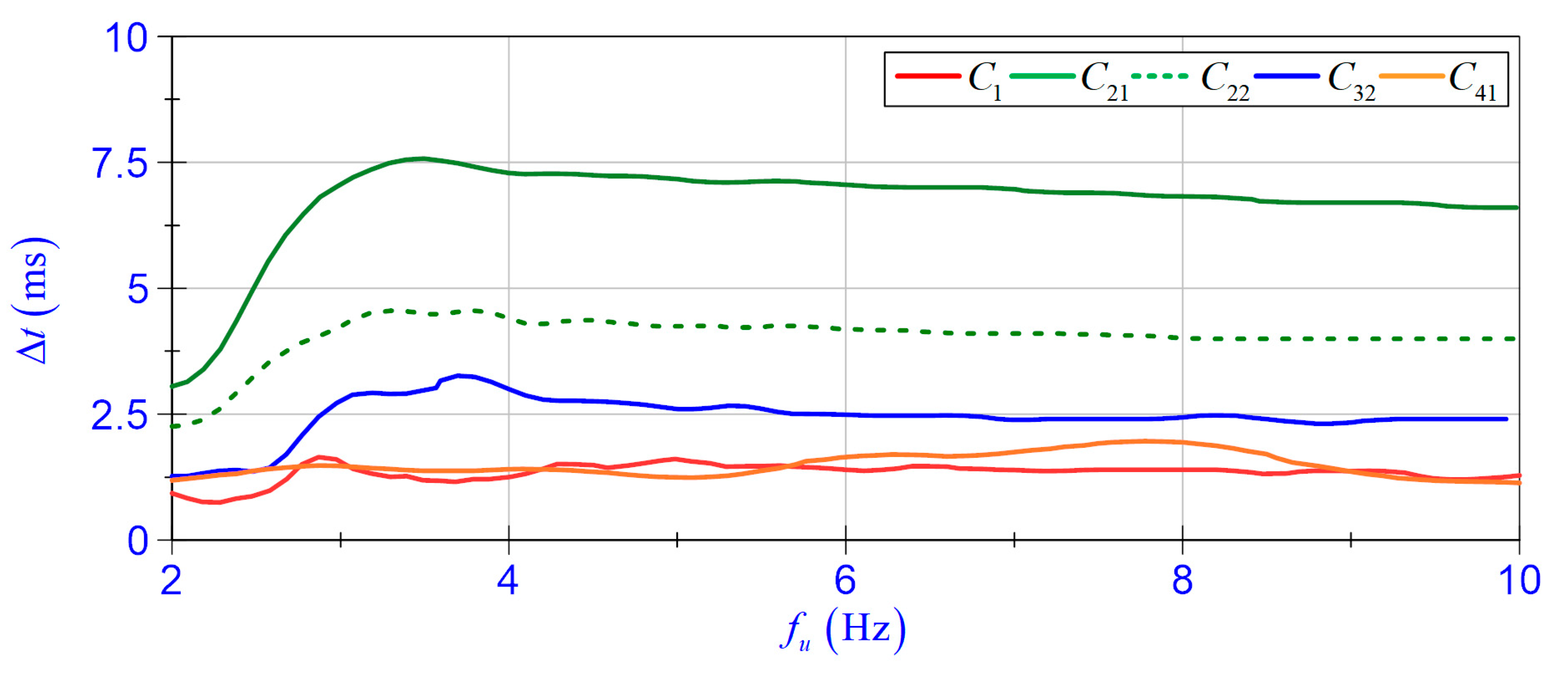
It should be noted that the time shift coefficient Δ t depends on the load of the EV-EH coil and frequency f u (see Figure 10). The adopted sampling frequency of measured values u , v r enabled determining the time shift coefficient Δ t with an accuracy of 0.1   ms .
The value of offset b was close to zero; therefore, it could be omitted. Moreover, at ambient temperatures from 20   to 29   , no significant impacts of the average EV-EH housing temperature T e h = mean (   t e h )   on the values of a and Δ t coefficients were noted (see Figure 11).
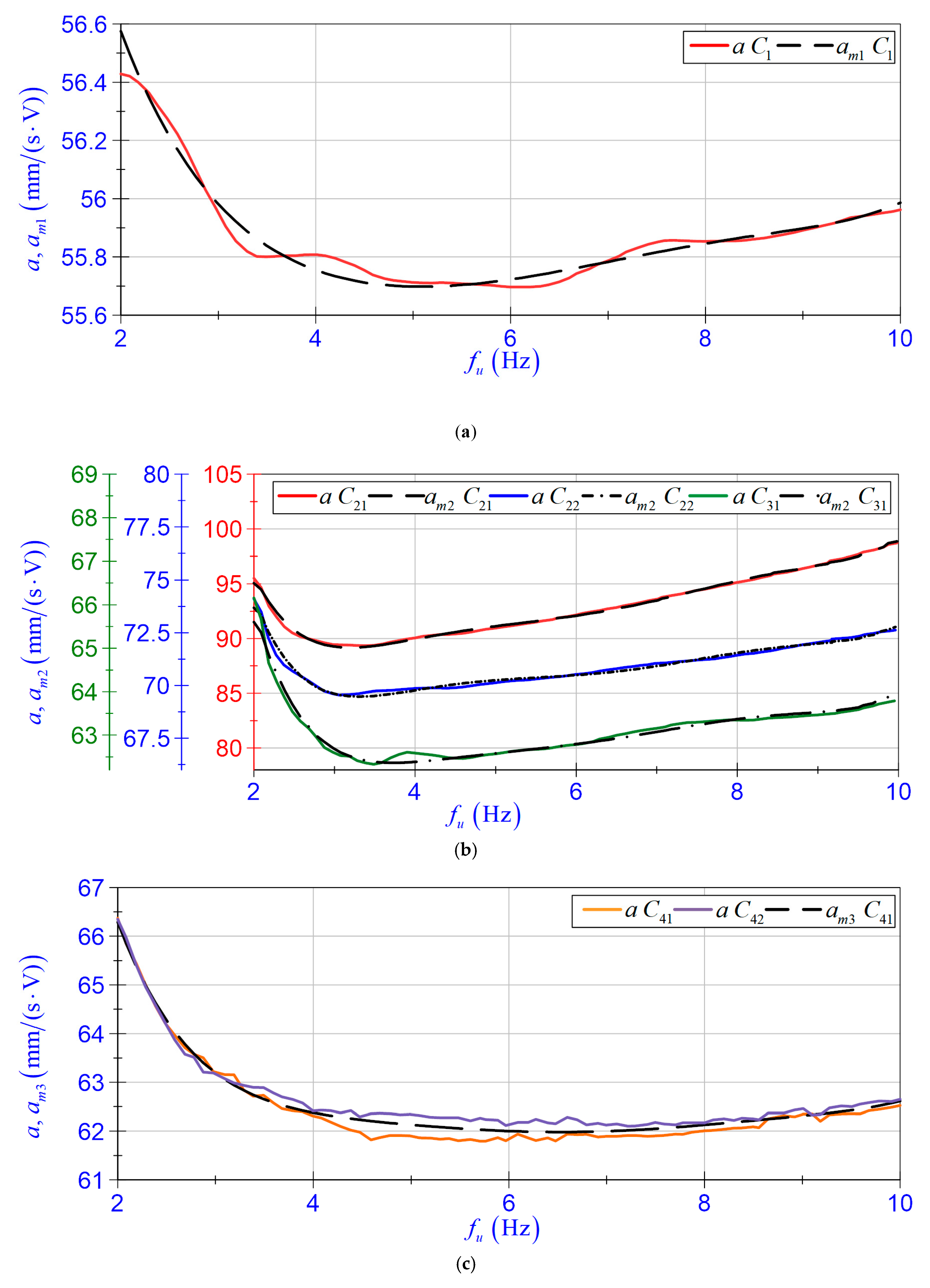
The relationship between gain a and frequency f z can be approximated with a sixth-degree polynomial:
a m = i = 0 6 a i · f u i
In order to determine the coefficients of a polynomial a m presented in Figure 6, the EV-EH coil load cases were divided into four groups:
  • Group 1 relates to case C 1 and the polynomial is denoted as a m 1 ;
  • Group 2 relates to cases C 21 , C 22 , C 23 , C 24 (where R l = R a ) and the polynomial is denoted as a m 2 ;
  • Group 3 relates to cases C 31 and C 32 (where R l = R b ) and the polynomial is denoted as a m 2 ;
  • Group 4 relates to cases C 41 and C 42 and the polynomial is denoted as a m 3 .
The calculated coefficients of polynomials a m 1 , a m 2 , and a m 3 are presented in Table 1. Polynomial a m 2 describes a generalised case where the EV-EH load resistance R l is known. The calculated coefficients of the polynomial a m 2 are a function of R l . Figure 12 shows the relationship between gain a and coefficients of polynomials a m 1 , a m 2 , and a m 3 as a function of frequency f u .
Polynomials a m 1 , a m 2 , and a m 3 correctly describe the changes of gain a ; therefore, the self-sensing function expressed in Equation (2) can be re-written as:
v u = ( i = 0 6 a i · f u i ) u t
The correctness of the determined v u function is proven by the values of linear correlation coefficient r given in Table 2, and the time patterns of v r and v u shown in Figure 13.

4.3.3. Self-Powered Capability

EV-EH’s primary function is to convert the mechanical energy of the magnets’ movement relative to the coil into electrical energy. The electrical energy generated by the harvester generates the instantaneous power defined as:
p a ( t ) = u ( t ) · i ( t )
Taking into account the energy conversion, the power flow p a depends on the relative velocity v r and the EV-EH coil load. As a result of the insignificant impact of the MR damper coil inductance L d ( C 41 , C 42 ) or L b ( C 31 , C 32 ), the power factor (ratio of active power and apparent power) is close to one, thus the self-powered capability can be expressed as a mean value of instantaneous power:
P a = mean ( p a )
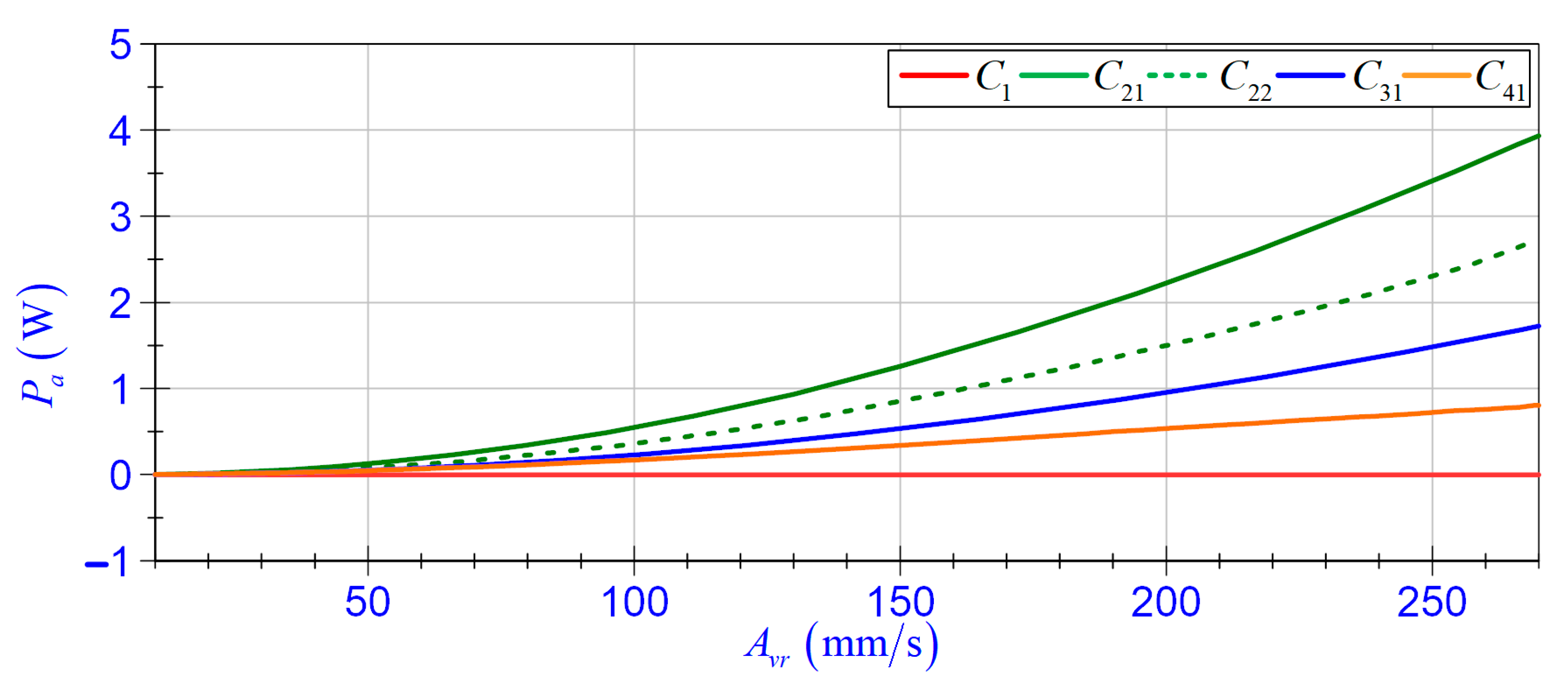
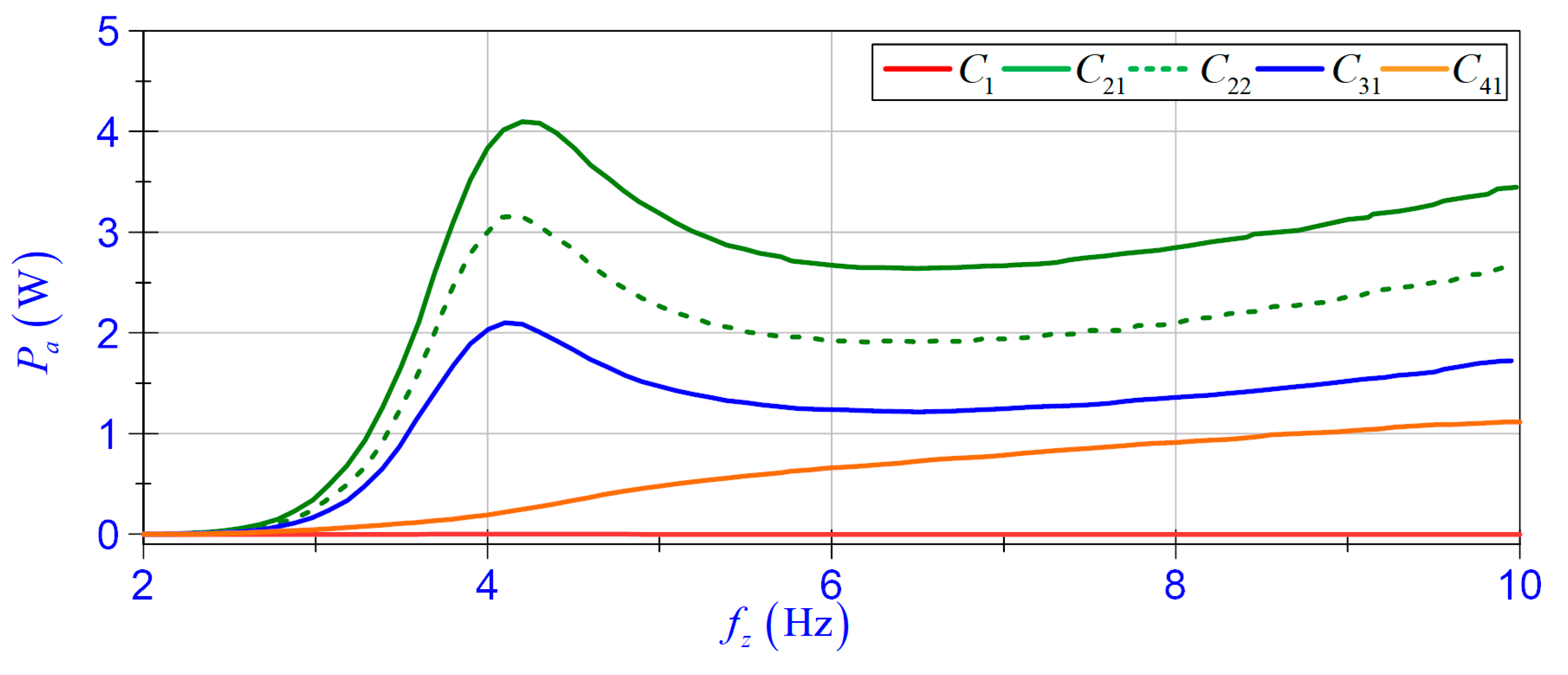
Figure 14 shows the active power P a as a function of the amplitude A v r . It should be noted that the amplitude A v r is a function of frequency f z (see Figure 15).

5. Self-Sensing and Self-Powered Action for Magnetorheological Damper Control

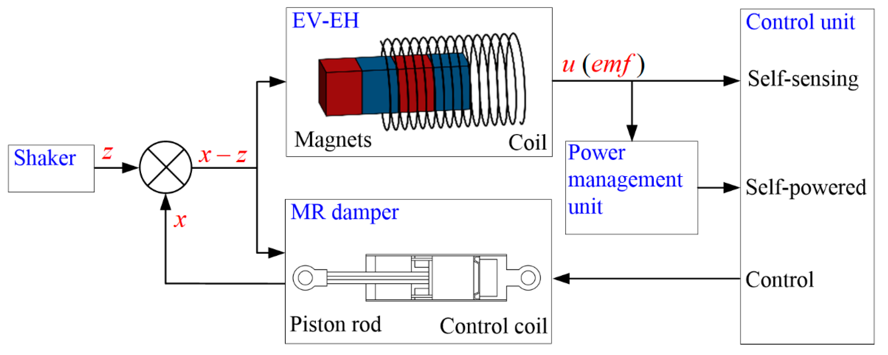
The diagram of the vibration reduction system with the self-sensing and self-powered action of the EV-EH to control the MR damper is shown in Figure 16. The EV-EH coil can be either directly connected to the MR control coil (case C41, C42) or via the power management unit and the control unit. It is apparent that the mechanical energy related to excitation z is converted to electrical energy. However, it should be considered that a portion of the mechanical energy is dissipated in the system as heat [31].
The control unit can be built based on a microprocessor system that forms a signal following the adopted control algorithm or based on a battery of bipolar electrolytic capacitors [32]. Regardless, it is important that the amount of recovered energy is greater than the electrical energy demand for the control unit, or in the case of its absence, the vibration reduction system acts in the configuration of a direct connection between the MR damper control coil and the EV-EH coil. The analysis of plots in Figure 15 indicates that the amount of recovered energy in some cases may be insufficient to power the control unit. Bearing this in mind, the implemented control unit was based on the low power consumption FPGA module, and the self-sensing function v u was used as a feedback signal in the control algorithm.
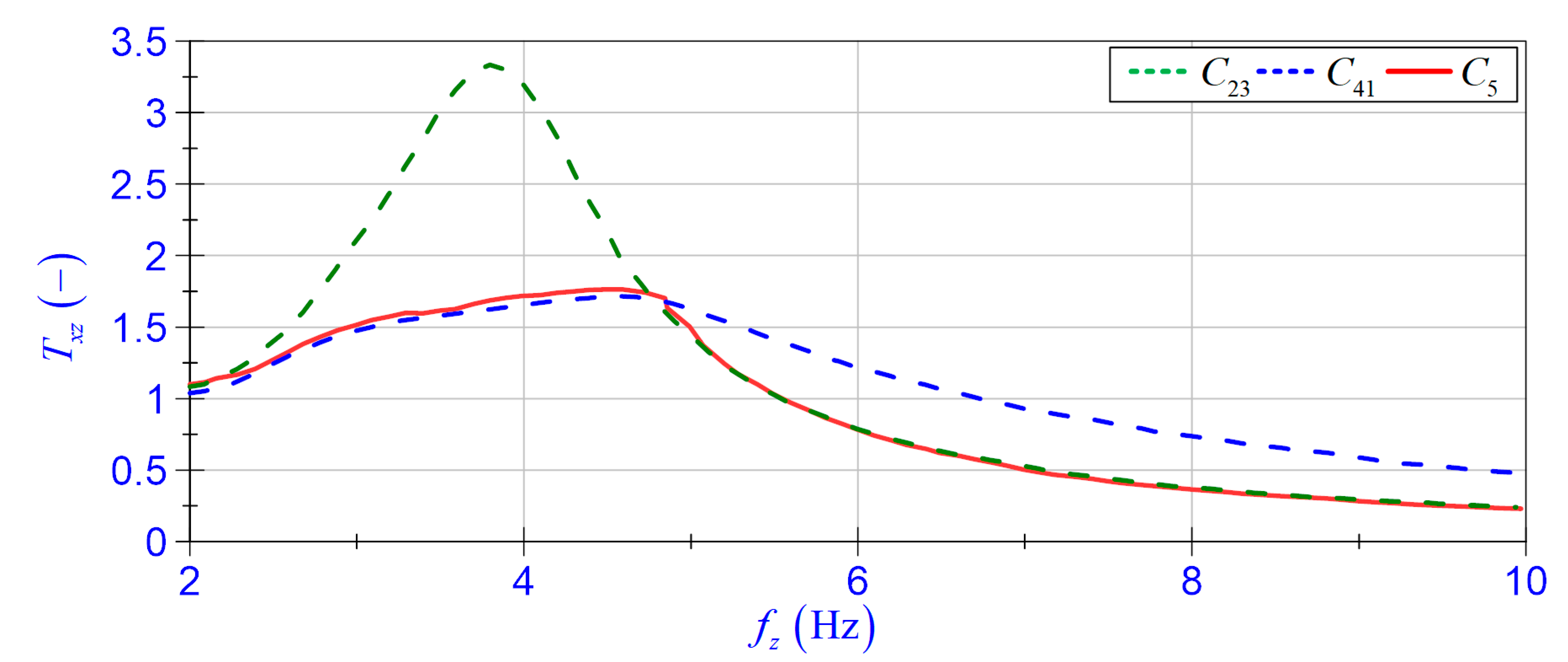
Figure 17 presents a practical implementation of the self-sensing and self-powered action in the vibration reduction system. The main elements of the system include the EV-EH, the MR damper, the resistance of the load R a = 5   Ω , the control unit, the energy meter, and the measurement system. The control unit consists of an ADC driver (analogue to digital converter), signal relay and embedded FPGA module DE10-Lite [33]. The application layer of the control algorithm was developed in the Quartus environment. The input voltage u was first converted into 0 5   V standard ( u s signal), then measured by a built-in FPGA ADC core. The control algorithm calculates the frequency f u and determines the self-sensing function. The self-sensing function was used to decide to switch the load using the I/O port and the relay from the MR damper coil to the R a resistance. Taking into account the displacement transmissibility T x z ( f z )   plots in Figure 7, the following values of control signal c s were used:
c s = { 0         f u 4.82   Hz 1         f u > 4.82   Hz
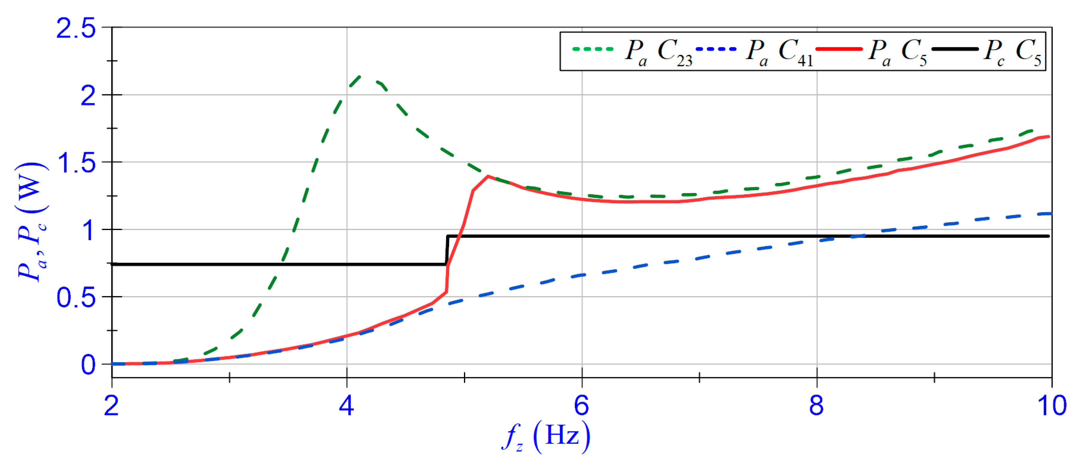
The energy meter was used to calculate the average power, P c , consumed by the control unit, and the active power. P a , generated by EV-EH. The self-sensing function v u determined by the control unit was sent (I2C) to the measurement system and was synchronised with relative velocity v r . Tests of the vibration reduction system, marked as a case C 5 , were performed for excitations ( 2 , 10 )   Hz and the temperature range ( 20 , 29 )   . The obtained results were used to determine displacement transmissibility T x z ( f z ) , self-sensing function v u ( t ) , power consumption P c ( f z ) , and active power P a ( f z ) (see Figure 18, Figure 19 and Figure 20).
The vibration reduction system effectiveness is determined by the coefficient T x z (see Figure 18). It can be seen that in the ( 2 , 4.9 )   Hz frequency range, the values of T x z coefficient in case C 5 are nearly the same as in case C 41 . However, at frequencies higher than 4.9   Hz , the values are nearly the same as in case C 23 . This proves that the studied system operated correctly.
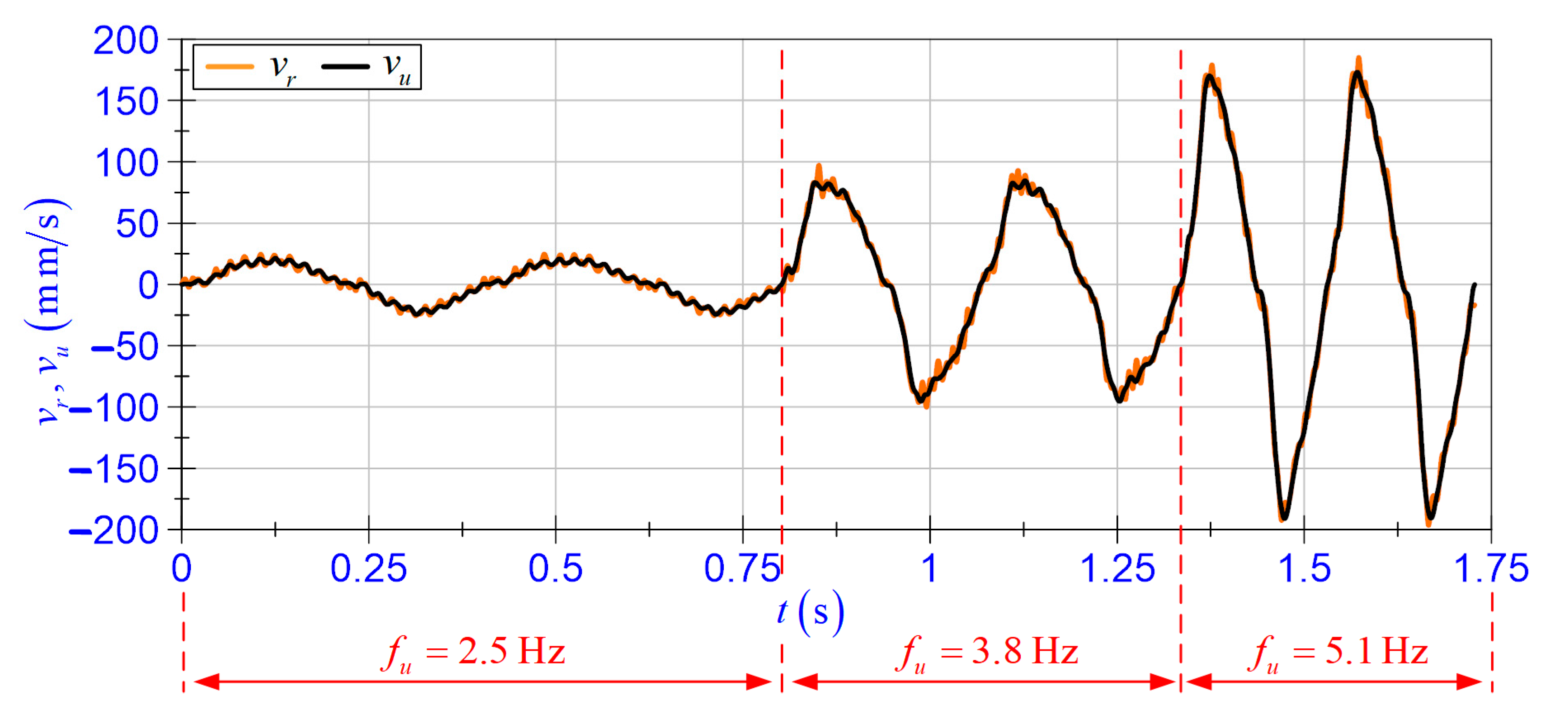
The self-sensing function v u was calculated by the control unit according to Equation (4) and gain function adopted in accordance with the values of polynomial coefficients a m 3 . The quality of representation of the relative velocity v r by self-sensing function v u can be assessed based on the values of linear correlation coefficient r and time patterns (see Table 4 and Figure 19). Figure 19 presents the time pattern of the self-sensing function v u and relative velocity v r at frequency f z = 3.8   Hz . As can be observed, the self-sensing function v u exhibited high accuracy when compared to the relative velocity v r .
In order to evaluate the benefits of using the self-sensing function, one should also take into account the energy consumption resulting from the use of additional transducers for the velocity measurement. Therefore, we also determined the power consumption and the standard deviation of measured velocity for the following transducers:
  • Polytec OFV-505 [34] laser vibrometer cooperating with an OFV-5000 decoder (direct velocity measurement);
  • FT50-RLA-70-PL5 [35] optical sensor running in speed mode with   1   kHz sampling frequency (in order to determine the velocity, differentiation of the recorded displacement is required);
  • Lika SME54-YC-2-PROG-R-L2 incremental linear encoder running at the programmed resolution 1   μ m (the velocity was determined as a quotient of constant displacement 1   μ m and the time-lapse measured by a clock with 40   MHz oscillator).
The results of measurements are presented in Table 3.
Taking into consideration power flows   P a and P c , it was shown that the value of average power consumption, P c , depended on the control signal, c s , and was equal to 0.74   W when c s = 0 and 0.95   W when c s = 1 . Additional energy consumption is a result of the current flow through the relay coil. The amount of consumed energy when c s = 1 can be reduced by modifying the switching function and using a latching relay with a double coil. The active power P a , calculated according to Equation (6), takes the values as nearly the same as in case C 41 (in the frequency range ( 2 , 4.9 )   Hz ) and C 23 (in the frequency range ( 4.9 , 10 )   Hz , see Figure 20).
Table 4 presents the selected parameters describing the self-sensing and self-powered action operation for the MR damper switching control. By comparing power flows P a and P c , it can be concluded that the amount of energy generated by EV-EH in the frequency range ( 4.9 , 10 ) Hz exceeded the amount of energy needed for a correct operation of the control unit. However, for frequencies below 4.9   Hz , the control unit requires an external source of energy or a store of energy generated from vibration.

6. Conclusions

This study included an investigation of the EV-EH self-sensing action. The research demonstrated that the EV-EH with a specific self-powered feature could also serve as a relative velocity sensor. For this purpose, the self-sensing function was proposed, and then the self-sensing action of the EV-EH was studied experimentally. The test results indicated a highly accurate monitoring capability of the device. The self-sensing and self-powered EV-EH features were applied to control the MR damper in the vibration reduction system. The results lead us to the following conclusions:
  • In the assumed range of excitations and the EV-EH coil load cases, the proposed self-sensing function v u represented the relative velocity v r with high accuracy;
  • The maximum values of the time shift coefficient Δ t revealed that the self-sensing function v u can be employed as a feedback signal in the vibration control systems;
  • The measure of uncertainty of the velocity v u depends on the standard deviation of voltage u and the EV-EH coil load resistance. Moreover, the standard deviation of the velocity value v u is comparable with standard deviation of the velocity obtained for commercial transducers;
  • In terms of the ambient temperature at which the study was conducted, it is not necessary to adjust the self-sensing function. In addition, the change in ambient temperature does not have a significant impact on the displacement transmissibility coefficient T x z of the system;
  • The average ratio of energy generated by the EV-EH may not be sufficient to power an industrial controller equipped with additional measuring transducers. However, replacing a transducer with a self-sensing function v u and use of a controller unit with low power consumption ensures powering the MR damper in the vibration control system;
  • The practical implementation of the self-sensing and self-powered actions for the MR damper switching control was demonstrated for loading an EV-EH coil with R a = 5   Ω resistance, although the reduction in this resistance increased the amount of recovered energy.
Further research will focus on developing the power management system and test other switching control algorithms.

Author Contributions

Conceptualisation, B.S.; validation of measurement sensors, P.O.; software implementation for the measurement and control systems, P.O.; planned and carried out experiments, B.S. and P.O.; processed data, B.S. and P.O.; data validation B.S.; supervision, B.S. Both authors have read and agreed to the published version of the manuscript.

Funding

This research was funded by the AGH University of Science and Technology within the scope of the research program No. 16.16.130.942 and Excellence Initiative—Research University.

Conflicts of Interest

The authors declare no conflict of interest.

References

  1. Cho, S.-W.; Jung, H.-J.; Lee, I.-W. Smart Passive System Based on Magnetorheological Damper. Smart Mater. Struct. 2005, 14, 707–714. [Google Scholar] [CrossRef]
  2. Choi, K.-M.; Jung, H.-J.; Lee, H.-J.; Cho, S.-W. Feasibility Study of an MR Damper-Based Smart Passive Control System Employing an Electromagnetic Induction Device. Smart Mater. Struct. 2007, 16, 2323–2329. [Google Scholar] [CrossRef]
  3. Sapiński, B. Energy-Harvesting Linear MR Damper: Prototyping and Testing. Smart Mater. Struct. 2014, 23, 035021. [Google Scholar] [CrossRef]
  4. Zhang, Y.; Huang, K.; Yu, F.; Gu, Y.; Li, D. Experimental Verification of Energy-Regenerative Feasibility for an Automotive Electrical Suspension System. In Proceedings of the 2007 IEEE International Conference on Vehicular Electronics and Safety, Beijing, China, 13–15 December 2007; pp. 1–5. [Google Scholar]
  5. Yu, M.; Peng, Y.; Wang, S.; Fu, J.; Choi, S.B. A New Energy-Harvesting Device System for Wireless Sensors, Adaptable to on-Site Monitoring of MR Damper Motion. Smart Mater. Struct. 2014, 23, 077002. [Google Scholar] [CrossRef]
  6. Chu, K.S.; Zou, L.; Liao, W.-H. A Mechanical Energy Harvested Magnetorheological Damper with Linear-Rotary Motion Converter. In Proceedings of the SPIE Smart Structures and Materials + Nondestructive Evaluation and Health Monitoring, Las Vegas, NV, USA, 20 April 2016; p. 980309. [Google Scholar]
  7. Choi, Y.-T.; Wereley, N.M. Self-Powered Magnetorheological Dampers. J. Vib. Acoust. 2009, 131, 044501. [Google Scholar] [CrossRef]
  8. Jung, H.-J.; Jang, D.-D.; Lee, H.-J.; Lee, I.-W.; Cho, S.-W. Feasibility Test of Adaptive Passive Control System Using MR Fluid Damper with Electromagnetic Induction Part. J. Eng. Mech. 2010, 136, 254–259. [Google Scholar] [CrossRef]
  9. Jung, H.-J.; Jang, D.-D.; Koo, J.-H.; Cho, S.-W. Experimental Evaluation of a ‘Self-Sensing’ Capability of an Electromagnetic Induction System Designed for MR Dampers. J. Intell. Mater. Syst. Struct. 2010, 21, 827–835. [Google Scholar] [CrossRef]
  10. Wang, D.H.; Bai, X.X.; Liao, W.H. An Integrated Relative Displacement Self-Sensing Magnetorheological Damper: Prototyping and Testing. Smart Mater. Struct. 2010, 19, 105008. [Google Scholar] [CrossRef]
  11. Wang, D.-H.; Bai, X.-X. A Magnetorheological Damper with an Integrated Self-Powered Displacement Sensor. Smart Mater. Struct. 2013, 22, 075001. [Google Scholar] [CrossRef]
  12. Peng, G.; Li, W.; Hu, G.; Alici, G. Design and Simulation of a Self- Sensing MR Damper. In Proceedings of the 15th International Conference on Mechatronics Technology, Melbourne, Australia, 30 November–2 December 2011; pp. 112–117. [Google Scholar]
  13. Chen, C.; Liao, W.-H. A Self-Sensing Magnetorheological Damper with Power Generation. Smart Mater. Struct. 2012, 21, 025014. [Google Scholar] [CrossRef]
  14. Rosół, M.; Sapiński, B. Ability of Energy Harvesting Mr Damper to Act as a Velocity Sensor in Vibration Control Systems. Acta Mechanica et Automatica 2019, 13, 135–145. [Google Scholar] [CrossRef] [Green Version]
  15. Zhu, S.; Shen, W.; Xu, Y. Linear Electromagnetic Devices for Vibration Damping and Energy Harvesting: Modeling and Testing. Eng. Struct. 2012, 34, 198–212. [Google Scholar] [CrossRef] [Green Version]
  16. Li, Z.; Zuo, L.; Kuang, J.; Luhrs, G. Energy-Harvesting Shock Absorber with a Mechanical Motion Rectifier. Smart Mater. Struct. 2012, 22, 025008. [Google Scholar] [CrossRef]
  17. Li, Z.; Zuo, L.; Luhrs, G.; Lin, L.; Qin, Y. Electromagnetic Energy-Harvesting Shock Absorbers: Design, Modeling, and Road Tests. IEEE Trans. Veh. Technol. 2013, 62, 1065–1074. [Google Scholar] [CrossRef]
  18. Ni, Y.Q.; Chen, Z.H.; Or, S.W. Experimental Identification of a Self-Sensing Magnetorheological Damper Using Soft Computing. J. Eng. Mech. 2015, 141, 04015001. [Google Scholar] [CrossRef]
  19. Chen, Z.H.; Ni, Y.Q.; Or, S.W. Characterization and Modeling of a Self-Sensing MR Damper under Harmonic Loading. Smart Struct. Syst. 2015, 15, 1103–1120. [Google Scholar] [CrossRef]
  20. Hu, G.; Ru, Y.; Li, W. Design and Development of a Novel Displacement Differential Self-Induced Magnetorheological Damper. J. Intell. Mater. Syst. Struct. 2015, 26, 527–540. [Google Scholar] [CrossRef] [Green Version]
  21. Hu, G.; Zhou, W.; Li, W. A New Magnetorheological Damper with Improved Displacement Differential Self-Induced Ability. Smart Mater. Struct. 2015, 24, 087001. [Google Scholar] [CrossRef]
  22. Xinchun, G.; Yonghu, H.; Yi, R.; Hui, L.; Jinping, O. A Novel Self-Powered MR Damper: Theoretical and Experimental Analysis. Smart Mater. Struct. 2015, 24, 105033. [Google Scholar] [CrossRef]
  23. Guan, X.; Ru, Y.; Huang, Y. A Novel Velocity Self-Sensing Magnetorheological Damper: Design, Fabricate, and Experimental Analysis. J. Intell. Mater. Syst. Struct. 2019, 30, 497–505. [Google Scholar] [CrossRef]
  24. Sapiński, B. Vibration Power Generator for a Linear MR Damper. Smart Mater. Struct. 2010, 19, 105012. [Google Scholar] [CrossRef]
  25. MR Damper, RD-8048-1, Technical Documentation. Available online: https://www.lord.com (accessed on 1 March 2021).
  26. Sapiński, B. Experimental Study of a Self-Powered and Sensing MR-Damper-Based Vibration Control System. Smart Mater. Struct. 2011, 20, 105007. [Google Scholar] [CrossRef]
  27. Electromagnetic Vibration Systems, LDSV780, Technical Documentation. Available online: https://www.bksv.com/en/instruments/vibration-testing-equipment/lds-shakers/low-force-shakers/lds-v780 (accessed on 1 March 2021).
  28. CompactRIO Controller, CRIO 9063, Technical Documentation. Available online: https://www.ni.com/pl-pl/support/model.crio-9063.html (accessed on 4 March 2021).
  29. Programmable Linear Incremental Encoder, SME54-YC-2-PROG-R-L2, Technical Documentation. Available online: https://www.lika.it/eng/products/linear-encoders/incremental-1/sme54 (accessed on 30 October 2020).
  30. Batterbee, D.; Sims, N.D. Temperature Sensitive Controller Performance of MR Dampers. J. Intell. Mater. Syst. Struct. 2009, 20, 297–309. [Google Scholar] [CrossRef] [Green Version]
  31. Sapiński, B.; Orkisz, P.; Jastrzębski, Ł. Experimental Analysis of Power Flows in the Regenerative Vibration Reduction System with a Magnetorheological Damper. Energies 2021, 14, 848. [Google Scholar] [CrossRef]
  32. Jastrzębski, Ł.; Sapiński, B. Magnetorheological Self-Powered Vibration Reduction System with Current Cut-Off: Experimental Investigation. Acta Mech. Autom. 2018, 12, 96–100. [Google Scholar] [CrossRef] [Green Version]
  33. Terasic DE10-Lite, User Manual. Available online: https://www.terasic.com.tw/cgi-bin/page/archive.pl?Language=English&CategoryNo=218&No=1021&PartNo=4 (accessed on 10 March 2021).
  34. Measuring Vibrations, Polytec OFV-505, Technical Documentation. Available online: https://www.polytec.com/us/vibrometry/products/single-point-vibrometers (accessed on 1 March 2021).
  35. Optical Sensor, FT 50RLA, Technical Documentation. Available online: https://www.sensopart.com/en (accessed on 30 October 2020).
Figure 1. Harvester structure (note: the dimensions are shown in millimetres).
Energies 14 02845 g001
Figure 2. Magnetic characteristics of magnets and ferromagnetic material.
Energies 14 02845 g002
Figure 3. MR damper structure.
Energies 14 02845 g003
Figure 4. Test rig layout.
Energies 14 02845 g004
Figure 5. Measurement system layout.
Energies 14 02845 g005
Figure 6. Harvester coil: (a) idle run; (b) under the load R a ; (c) under the load R b L b ; (d) under the load R d L d (MR damper coil).
Energies 14 02845 g006
Figure 7. Displacement transmissibility T x z vs. frequency f z .
Energies 14 02845 g007
Figure 8. MR damper housing temperature T e d vs. frequency f z .
Energies 14 02845 g008
Figure 9. Relative velocity amplitude A v r vs. frequency f z .
Energies 14 02845 g009
Figure 10. Time shift coefficient Δ t vs. frequency f u .
Energies 14 02845 g010
Figure 11. (a) Mean value of harvester housing temperature T e h vs. frequency f u ; (b) gain a and time shift coefficient Δ t vs. frequency f u .
Energies 14 02845 g011
Figure 12. Gain coefficients a and a m vs. frequency f u for (a) C 1 ; (b) C 21 , C 22 , C 31 ; (c) C 41 , C 42 .
Energies 14 02845 g012
Figure 13. Time patterns of velocity v r and v u for C 41 .
Energies 14 02845 g013
Figure 14. Active power P a vs. relative velocity amplitude A v r .
Energies 14 02845 g014
Figure 15. Active power P a vs. frequency f z .
Energies 14 02845 g015
Figure 16. Vibration reduction system with MR damper using self-sensing and self-powered action.
Energies 14 02845 g016
Figure 17. Self-sensing and self-powered action for MR damper switching control.
Energies 14 02845 g017
Figure 18. Displacement transmissibility T x z vs. frequency f z .
Energies 14 02845 g018
Figure 19. Time patterns of velocity v r and v u for C 5 and f z = 3.8   Hz .
Energies 14 02845 g019
Figure 20. Active power P a and consumed power P c vs. frequency f z .
Energies 14 02845 g020
Table 1. Values of polynomial a m coefficients.
Factor a m 1 a m 2 a m 3
a 0 60.8054 301.057 74.356 · R l + 7.3386 · R l 2 99.3889
a 1 3.9928 213.458 + 57.6952 · R l 5.0494 · R l 2 34.7622
a 2 1.3537 95.5819 26.2113 · R l + 2.2804 · R l 2 13.5935
a 3 0.2598 21.9491 + 6.1191 · R l 0.5352 · R l 2 2.8176
a 4 2.9669 e 2 2.7486 0.7823 · R l + 6.9506 e 2 · R l 2 0.3234
a 5 1.8620 e 3 0.1780 + 5.1761 e 2 · R l 4.6924 e 3 · R l 2 1.9399 e 2
a 6 4.9073 e 5 4.6674 e 3 1.3857 e 3 · R l + 1.2831 e 4 · R l 2 4.7525 e 4
Table 2. Values of linear correlation coefficient r .
Frequency   f u Coefficient   r   for   a m 1   ( C 1 ) Coefficient   r   for   a m 2   ( C 31 ) Coefficient   r   for   a m 3   ( C 41 )
2.5   Hz 0.9760 0.9842 0.9761
3.0   Hz 0.9958 0.9956 0.9913
4.0   Hz 0.9969 0.9975 0.9939
5.5   Hz 0.9976 0.9983 0.9966
7.0   Hz 0.9971 0.9980 0.9940
9.0   Hz 0.9972 0.9970 0.9907
Table 3. The standard deviation of measured velocity and power consumption of transducers.
TransducersStandard Deviation of Velocity
mm / s
Power Consumption
W
Laser vibrometer Polytec OFV-505 0.52 67.216
Optical distant sensor FT50-RLA-70-PL5 2.57 0.912
Linear encoder SME54-YC-2-PROG-R-L2 1.23 0.313
Absence (self-sensing function for case ( C 41 ) 1.66 0
Table 4. Factors of self-sensing and self-powered operation at the various frequency in case C 5 .
Frequency   f z   Hz Displacement   Transmissibility   T x z Correlation   Coefficient   r between   v u   and   v r Active   Power   P a   W Power   Consumption   P c   W Power   Excess   P a P c   W
2.0 1.100 0.8734 0.002 0.74 0.738
3.0 1.516 0.9903 0.048 0.74 0.692
4.0 1.720 0.9931 0.207 0.74 0.533
5.0 1.505 0.9961 1.034 0.95 0.084
6.0 0.782 0.9984 1.223 0.95 0.273
7.0 0.506 0.9981 1.219 0.95 0.269
8.0 0.366 0.9964 1.324 0.95 0.374
9.0 0.284 0.9966 1.484 0.95 0.534
10.0 0.230 0.9977 1.690 0.95 0.740
Publisher’s Note: MDPI stays neutral with regard to jurisdictional claims in published maps and institutional affiliations.