Article

PV Modules Interfacing Isolated Triple Active Bridge for Nanogrid Applications

1
Department of Architecture and Engineering, University of Parma, Parco Area delle Scienze, 181/A, 43124 Parma, Italy
2
Electronic Technology Department, Faculty of Engineering in Bilbao, University of the Basque Country (UPV/EHU), Alameda de Urquijo s/n, 48013 Bilbao, Spain
*
Author to whom correspondence should be addressed.
Energies 2021, 14(10), 2854; https://doi.org/10.3390/en14102854
Submission received: 17 March 2021 / Revised: 5 May 2021 / Accepted: 10 May 2021 / Published: 15 May 2021
(This article belongs to the Special Issue Conversion and Generation from Renewable Energy)

Abstract

:
DC nanogrid architectures with Photovoltaic (PV) modules are expected to grow significantly in the next decades. Therefore, the integration of multi-port power converters and high-frequency isolation links are of increasing interest. The Triple Active Bridge (TAB) topology shows interesting advantages in terms of isolation, Zero Voltage Switching (ZVS) over wide load and input voltage ranges and high frequency operation capability. Thus, controlling PV modules is not an easy task due to the complexity and control stability of the system. In fact, the TAB power transfer function has many degrees of freedom, and the relationship between any of two ports is always dependent on the third one. In this paper we analyze the interfacing of photovoltaic arrays to the TAB with different solar conditions. A simple but effective control solution is proposed, which can be implemented through general purpose microcontrollers. The TAB is applied to an islanded DC nanogrid, which can be useful and readily implemented in locations where the utility grid is not available or reliable, and applications where isolation is required as for example More Electric Aircraft (MEA). Different conditions have been simulated and the control loops are proved for a reliable bus voltage control on the load side and a good maximum power point tracking (MPPT).

1. Introduction

Distributed generation (DG) research is pressed from the environmental issues and the global need to increase a sustainable access to electricity. The main disadvantages of DG can be identified in the intermittent nature of its power output and financial capital required. Therefore, DG pushes research for smart energy management and dedicated architectures. DC nanogrids result as an interesting option and are proposed in numerous system architectures and strategic future visions [1]. Already today, we can see how important DC nanogrids can be for everyday-use applications such as the energy management in laptops or electric vehicles. At the same time, many advantages compared to AC nanogrids have been stated for DC nanogrids, first of all, an improved overall efficiency [2]. Thus, the implementation in today’s industrialized countries of residential DC nanogrid architectures requires an important retrofit, either replacing AC loads with the limited DC compatible loads available on the market, or modifying the AC loads to work in DC mode [3].
A different situation can be identified in developing countries, but also in small islands, rural and mountain areas, or transport vehicles, where grid-islanded architectures are of important interest due to: the high cost of the utility grid connection (e.g., long cables for small loads); not reliable local power grid; inability to connect to a local grid with fixed cables (e.g., power distribution on aircrafts, or ships). In these applications, DC nanogrids could be easily implemented with multi-port DC/DC converters, such as TAB converters. The TAB converter topology has been of growing interest in the last years. Applications, where it is mostly proposed, are nanogrids or microgrids for storage backup interface for data centers [4], MEA [5] and ships [6].
In a future view, other applications can gain a particular interest in TAB-based nanogrids with PV panels. For example, MEA could include solar panels for hybrid systems and a battery charge through solar energy. For security purposes, the buses on a conventional passenger aircraft should be electrically insulated from each other. Therefore, high-frequency link DC/DC converters are the most adopted solution, and TAB has important potentialities [7].
First simulations and experimental results of TAB converters are shown in [8], then continued in [9], where a TAB interfaces a fuel cell, a battery and loads. In these applications, the TAB needs a power flow control in order to facilitate the exchange of power between the low transient response of fuel cells and the faster battery.
In this work, the TAB is proposed to interface PV modules, batteries and DC loads. Interfacing a PV array to the TAB is not an easy task and not deeply studied in the literature. The converter should be able to achieve a good MPPT and bus voltage control. In literature, similar architectures can be found, but with different characteristics or control objectives. In [10], the modeling of a TAB converter is proposed for electric vehicle on-board charger applications. Here the control loops are current-oriented, and the voltages on the three-ports are fixed. In [11] the PV is interfaced through a converter with MPPT algorithm, and the control strategy is applied to achieve fixed bus voltage and power flow from or to the grid by fixing the PV side port voltage. This could be an effective solution also for the architecture considered here with the addition of an MPPT converter, thus introducing a conversion stage and reducing the overall efficiency. In [12] a current control strategy is proposed on the same architecture based on the decoupling matrix defined in [13]. Thus, precise, fast and reliable current sensors, conditioning circuits and calculation algorithms are required. Furthermore, considering PV modules interfacing the TAB, setting the reference current from an MPPT controller is not trivial due to the voltage non-linear dependence on both power transfer and MPPT tracking. In fact, the decoupling matrix is calculated assuming constant voltages, and gains are calculated based on the voltages themselves. The same is true for [14,15], where the architecture is proposed in a larger grid-integrated system, where PV modules compensated with batteries adjust the power flow into the grid. In [16], PV is interfaced through a boost converter to a non-isolated DC link, and the battery is connected through a bidirectional converter in order to control the power flow.
This paper analyzes the TAB as a key element of an islanded DC nanogrid with galvanic isolation between source, storage, and DC bus, where the conversion stages are limited to the TAB and possible DC/DC converters on the load side (Figure 1). Applications where it can be applied are residential energy management, but also MEA with solar panels, ships or electric vehicles where port isolation is required. The architecture can be expanded with a Dual Active Bridge (DAB) for a grid connection and a smart central control can be applied as proposed in [17].
In this work, accurate models are used to prove the control loops, and simulation results are provided to show the PV, battery and bus powers, voltages and currents. The control algorithms for the PV and battery interface are simulated with different irradiation and temperature conditions. The main contribution of the proposed control is the simple implementation. Using complex matrix decoupling systems is not always possible with general-purpose microcontrollers. Design considerations on PV and battery sizing can be made starting from the required output power and the State of Charge (SoC) provided by simulations. Section 2 of the paper introduces the TAB and analyzes the nanogrid architecture. The main power transfer equations, the requirements and the specifications are shown. Section 3 and Section 4 show the bus control loop and the MPPT control loop definition, respectively. In this work, the transfer functions have been extracted with MATLAB Simulink and SISOtool (Release 2020a, The MathWorks, Inc., Natick, MA, USA). The simulated model and parameters are described in Section 5. In this section, the mathematical modeling of PV and battery is shown, together with the asymmetric PWM generation algorithm. In Section 6, early experimental results are shown only for model validation through a first prototype. Finally, simulation results are shown and discussed in Section 7.

2. TAB and Analyzed Nanogrid Architecture

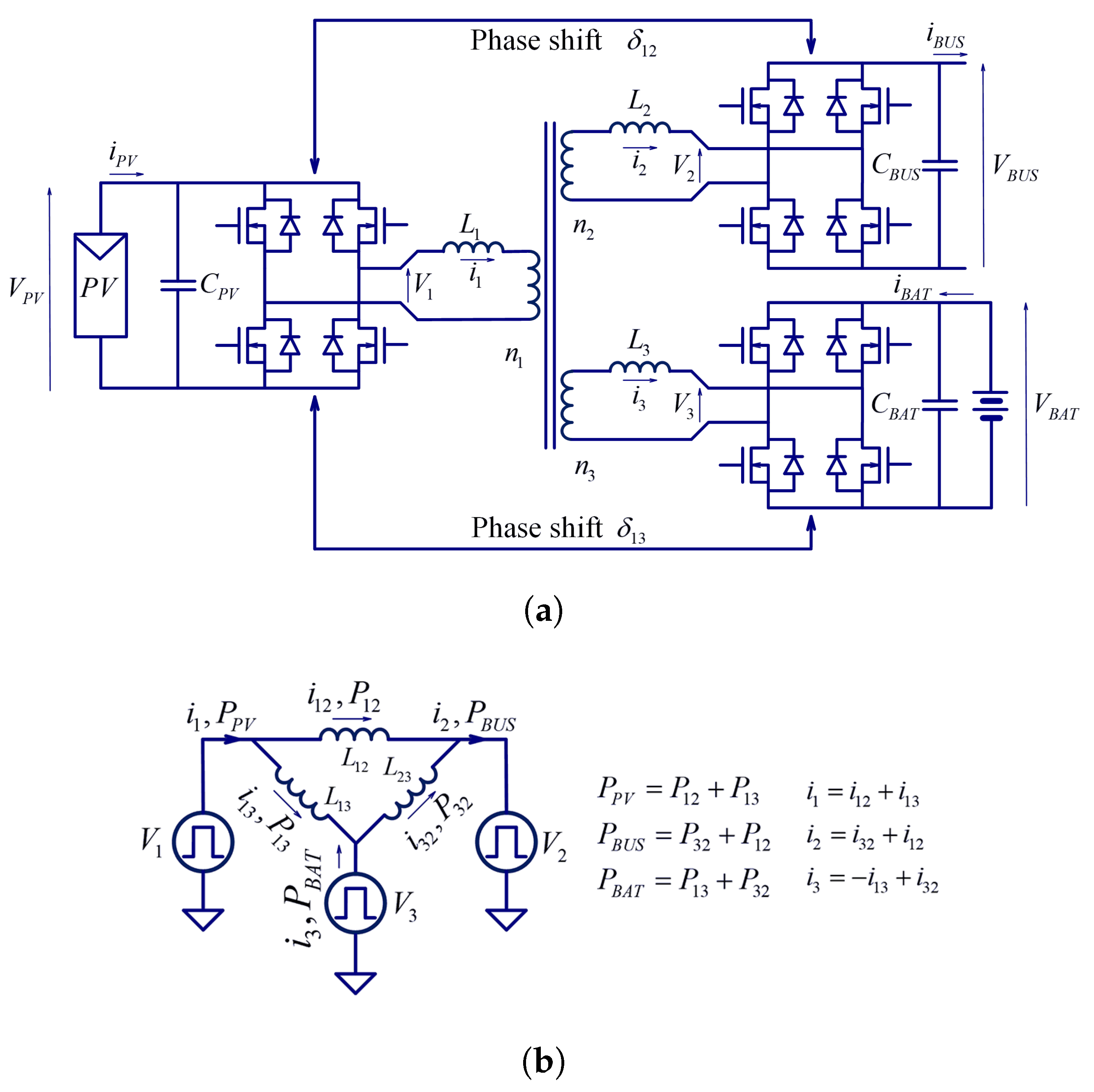
The circuit diagram and the Δ -transformed equivalent model of the TAB used in this paper are shown in Figure 2a,b, respectively.
The TAB power transfer equations can be extracted from the Δ -equivalent model analysis, where the magnetizing current is negligible with respect to the load current, under loaded condition. Therefore, the magnetizing inductance L m is not considered in the power transfer equations. With load convention on the load side, the three-port power transfer equations can be defined as [18]:
P P V = V P V V b u s 2 f S L 12 δ 12 ( 1 | δ 12 | ) + V P V V B A T 2 f S L 13 δ 13 ( 1 | δ 13 | ) ,
P b u s = V P V V b u s 2 f S L 12 δ 12 ( 1 | δ 12 | ) + V B A T V b u s 2 f S L 23 ( δ 12 δ 13 ) ( 1 | δ 12 δ 13 | ) ,
P B A T = V B A T V b u s 2 f S L 23 ( δ 12 δ 13 ) ( 1 | δ 12 δ 13 | ) V P V V B A T 2 f S L 13 δ 13 ( 1 | δ 13 | ) ,
where:
L 12 = L 1 L 2 + L 1 L 3 + L 2 L 3 L 3 ,
L 13 = L 1 L 2 + L 1 L 3 + L 2 L 3 L 2 ,
L 23 = L 1 L 2 + L 1 L 3 + L 2 L 3 L 1
δ 12 and δ 13 are the π -normalized phase shifts between the three square voltages applied to the transformer. P P V represents the power transfer from the PV module to the system, P b u s the total power absorbed by the load, P B A T the power balance on the battery side, which results negative if the battery is absorbing power. V P V , V B A T and V b u s represent the voltages on the PV, battery and bus ports, respectively. L 1 , L 2 and L 3 represent the leakage inductances and possible external inductors between the full bridges, and the transformer and f s represent the switching frequency.
Considering Equations (1)–(3), the transferable power is determined from the voltage levels, the two-phase shifts, the working frequency f s and the inductances L 12 , L 23 , L 13 . Voltages are defined by the application, and the two normalized phase shifts are limited from 0 to 0.25. Therefore, a trade-off must be identified between the maximum transferable power and the passive component sizes. In fact, if the working frequency is reduced, the transformer will be unavoidably bigger. At the same time, the value of the leakage inductance can be reduced to increase the power transfer.
In this paper we consider a 1:1:1 turns ratio transformer. Due to the wide capable operating conditions of the TAB, the control loop definition is not heavily affected by the transformer turn ratio. To optimize and improve the TAB efficiency, a different turn ratio on the side of the PV modules can be defined in dependence of the connected array voltage, as well as an optimized design of series inductance, zero voltage switching (ZVS) control or different phase-modulation [19,20,21]. In fact, the switching frequency and series inductance are key parameters for defining a trade-off between the control simplicity, power transfer capability, current peaks, and converter costs and sizes. From Equations (1)–(3), increasing the switching frequency or series inductance results in a reduced power transfer capability. Nevertheless, reducing series inductance leads to lower voltage drops between the transformer ports. Therefore, limiting the voltage deviation range between the TAB ports.
The PV interface analysis is provided on a low voltage DC nanogrid architecture where the TAB is inserted as a key element. PV modules are used as generators only source, battery as a storage unit and a 48 V voltage bus is controlled, where loads can be applied directly, or through DC/DC converters. Table 1 lists the parameters of the chosen architecture.
The maximum PV power is defined from three series-connected 240 W PV modules. The maximum load capacity is an approximation obtained from Equation (2), calculated with the architecture parameters.
Defining the control strategy for a TAB interfacing PV modules is not an easy task. The non-linear, mutual-dependent transfer functions of the power transfers over phase shift can be synthesized only assuming constant voltages on two ports. In this case, linear controllers can be applied with a properly calculated decoupling matrix as in [22]. A strategy to avoid a complex decoupling matrix has been presented in [23], but in the case of PV modules, power-sharing changes both with phase shift and PV voltage, according to an interdependent and complex transfer function. Therefore, assuming PV modules connected directly to the TAB, one linear controller can be applied for the bus voltage, while the power-sharing between the three ports can be controlled with a proper MPPT algorithm and the proposed feed-forward control on the load current, which acts as a simple decoupling network.

3. Bus Control Loop

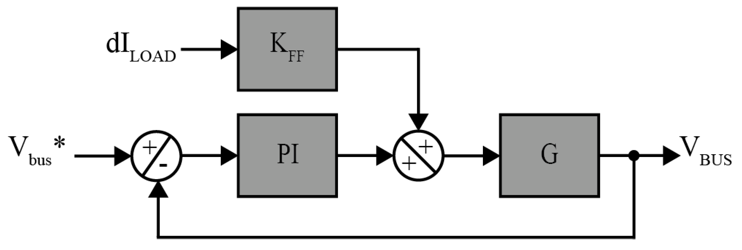
The bus control loop architecture is shown in Figure 3. The transfer function G is a linearization of the more complex transfer function between the output voltage and phase shift between the first and the second port. In this work, the transfer function has been extracted with MATLAB SISOtool.
Extracting from the equations shown in [24], the second port output voltage can be expressed as follows:
V b u s = R L O A D · { [ V P V 2 f S L 12 ( 1 | 2 δ 12 | ) + V B A T 2 f S L 23 ( 1 | 2 δ 12 2 δ 13 | ) ] × δ 12 τ s + 1 + [ V B A T 2 f S L 23 ( | 2 δ 12 2 δ 13 | 1 ) ] × δ 13 τ s + 1 + [ 1 2 f S L 12 δ 12 ( 1 | δ 12 | ) ] × V P V τ s + 1 + [ 1 2 f S L 23 ( δ 12 δ 13 ) ( 1 | δ 12 δ 13 | ) ] × V B A T τ s + 1 } .
In this equation, considering as dominant the pole due to the output capacitor, τ can be evaluated as follows:
τ = R L O A D · C b u s = 4.23 × 10 3 s .
Therefore, if we apply a fast controller for the bus voltage loop and a ten-times slower controller on the MPPT control loop, some terms can be considered as constants and the V b u s reaction over δ 12 around notable points can be defined:
V b u s δ 12 = R L O A D · [ V P V 2 f S L 12 4 δ 12 V P V 2 f S L 12 + V B A T 2 f S L 23 4 δ 12 V B A T 2 f S L 23 + 2 δ 13 V B A T 2 f S L 23 + V P V 2 f S L 12 2 δ 12 V P V 2 f S L 12 + V B A T 2 f S L 23 2 δ 12 V B A T 2 f S L 23 + 2 δ 13 V B A T 2 f S L 23 ] × 1 τ s + 1 ,
V b u s δ 12 | δ 12 = 0 , δ 13 = 0 , V P V = 0 = 1136.84 4.23 × 10 3 s + 1 ,
V b u s δ 12 | δ 12 = 0.25 , δ 13 = 0 , V P V = 0 = 284.21 4.23 × 10 3 s + 1 ,
V b u s δ 12 | δ 12 = 0.25 , δ 13 = 0.1 , V P V = V P V M P P = 816.09 4.23 × 10 3 s + 1 .
The MATLAB SISOtool can be used to speed up design. By applying a step signal on δ 12 , with δ 13 = 0 , a 93.4% fit to estimation data is found on the extracted transfer function in open loop:
V b u s δ 12 = 921.78 4.12 × 10 3 s + 1 .
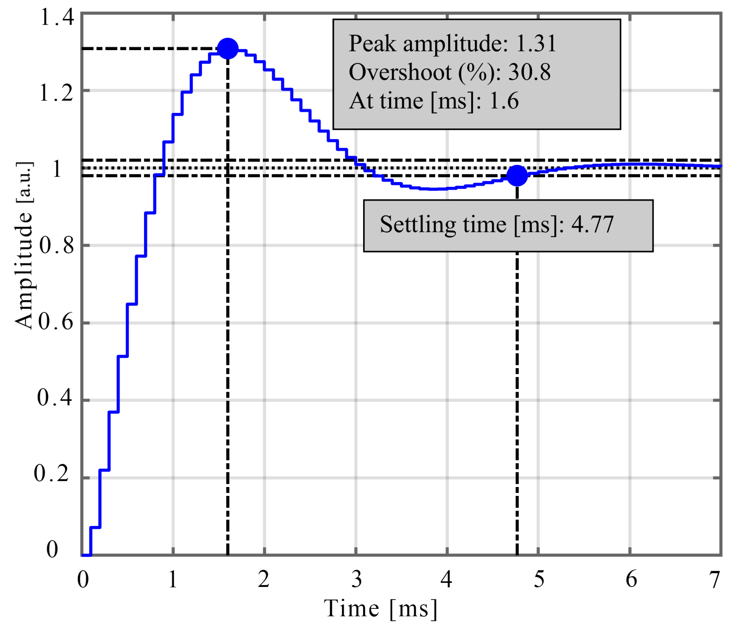
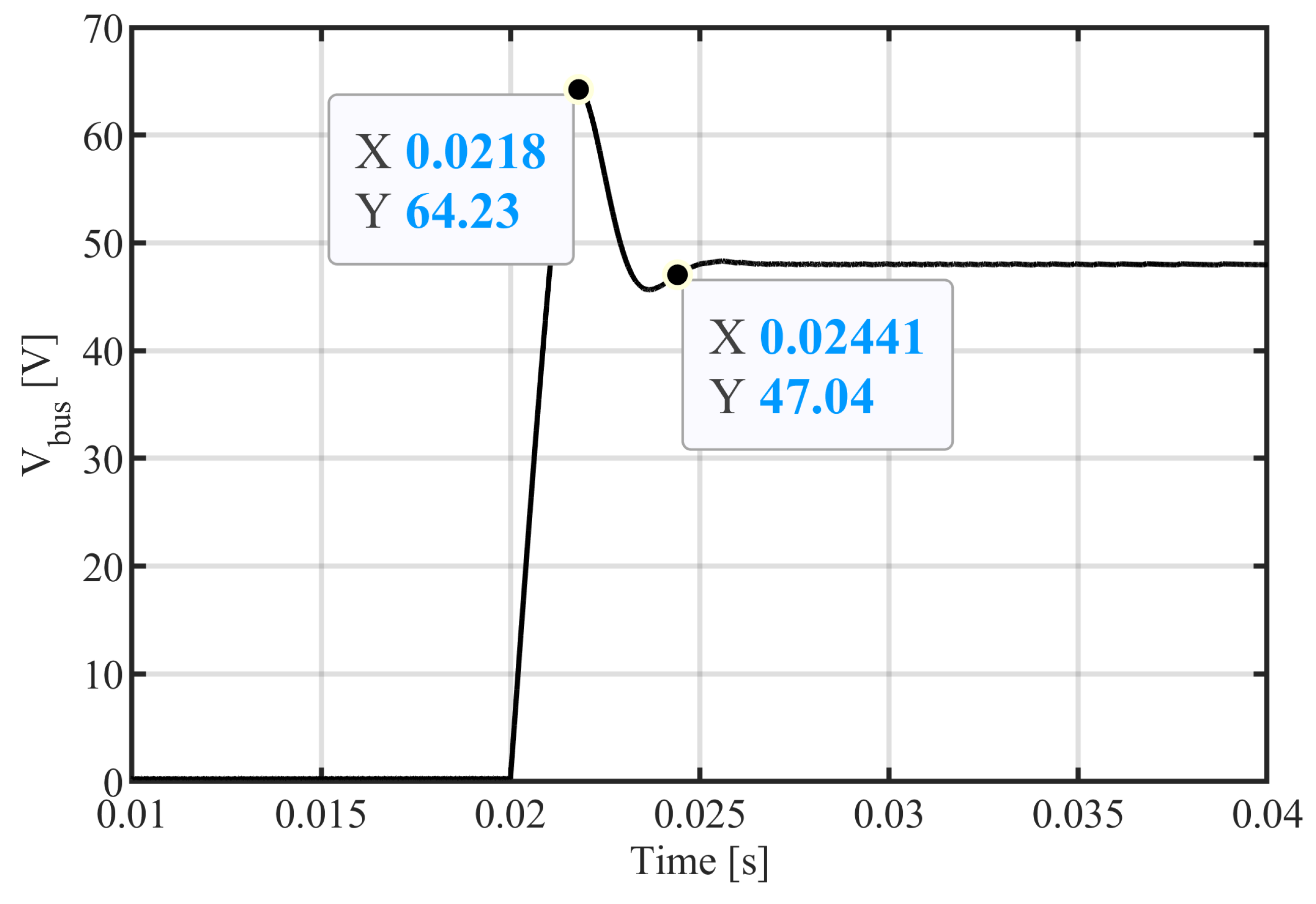
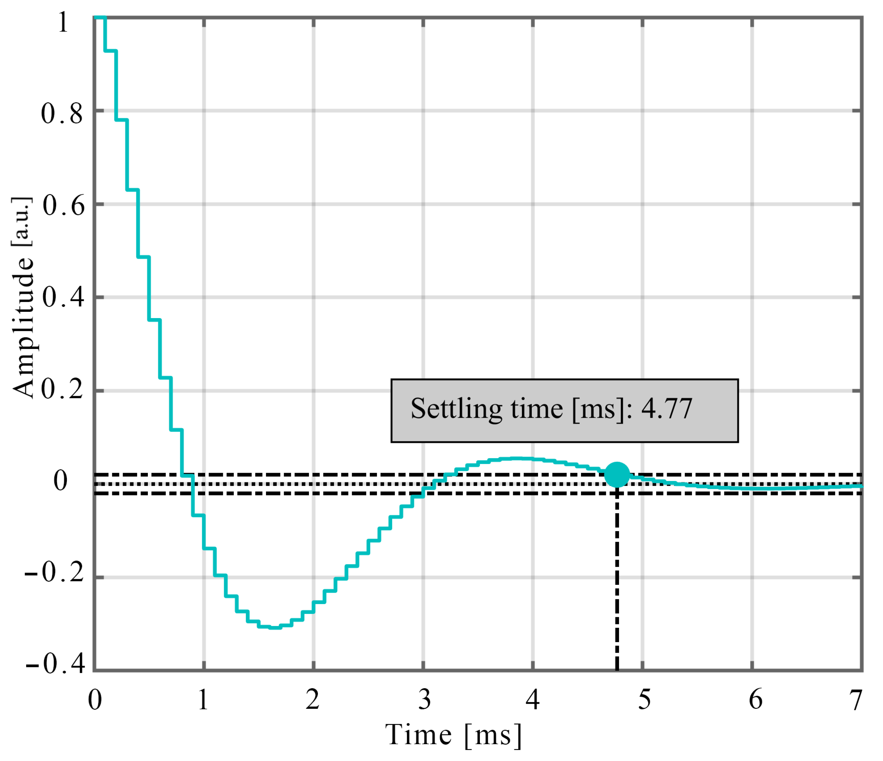
Therefore, proportional and integral constants have been defined, allowing a good rejection of step disturbance, with the aim of keeping the voltage constant on the load bus with a low ripple. Considering also a current feedforward, that will be explained in Section 4, the integral constant has been chosen to be 10 and the proportional constant 6 × 10 3 . In Figure 4 the response to step command is shown through MATLAB SISOtool, while Figure 5 shows the simulation results for a bus voltage step from 0 to 48 V, with a load of 9 Ω (without current feed-forward).
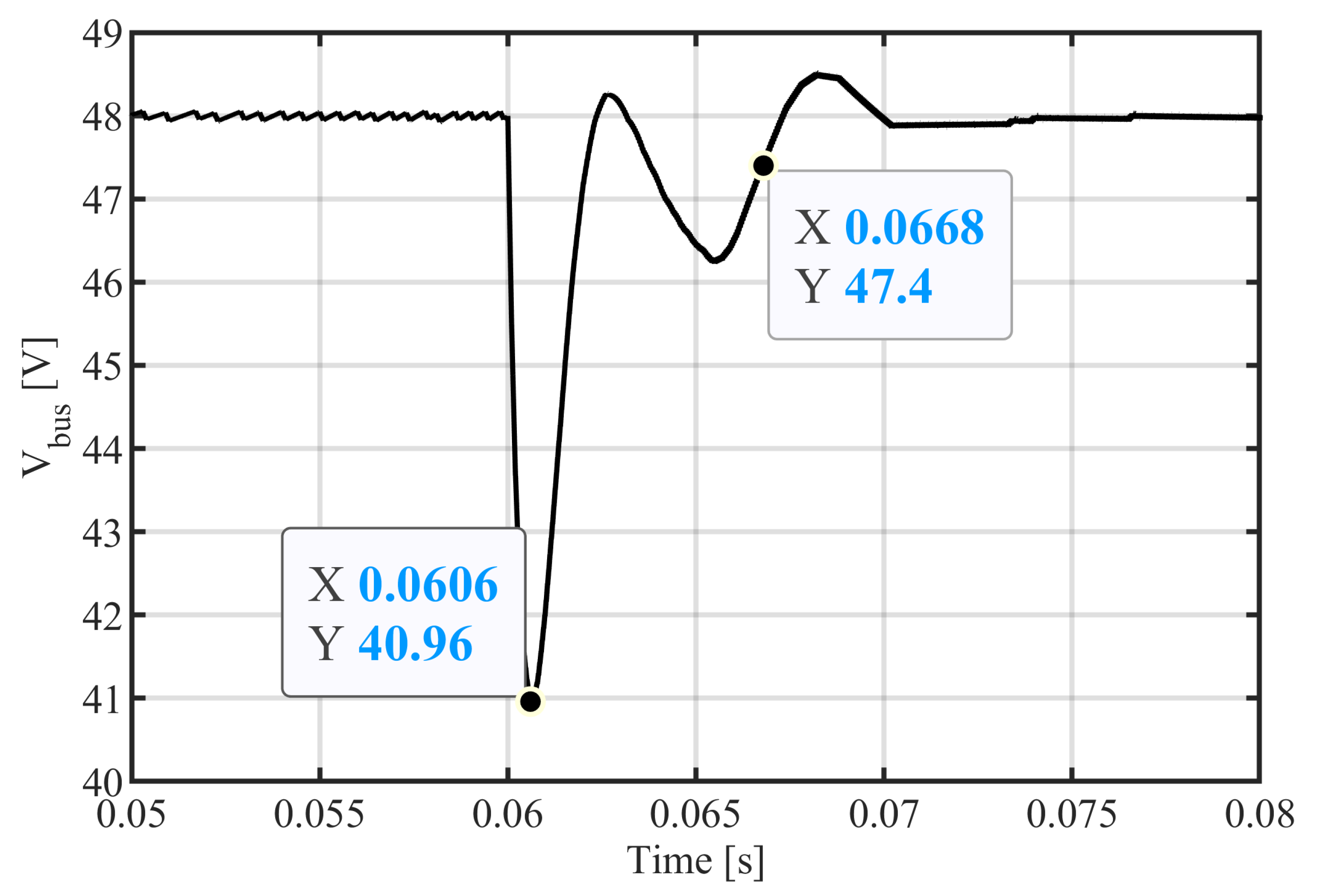
Figure 6 shows the SISOtool step rejection response, while in Figure 7 the simulation result of the rejection of step disturbance is shown with a change in load from 36 to 9 Ω , with no power flow from the PV module.

4. MPPT Control Loop

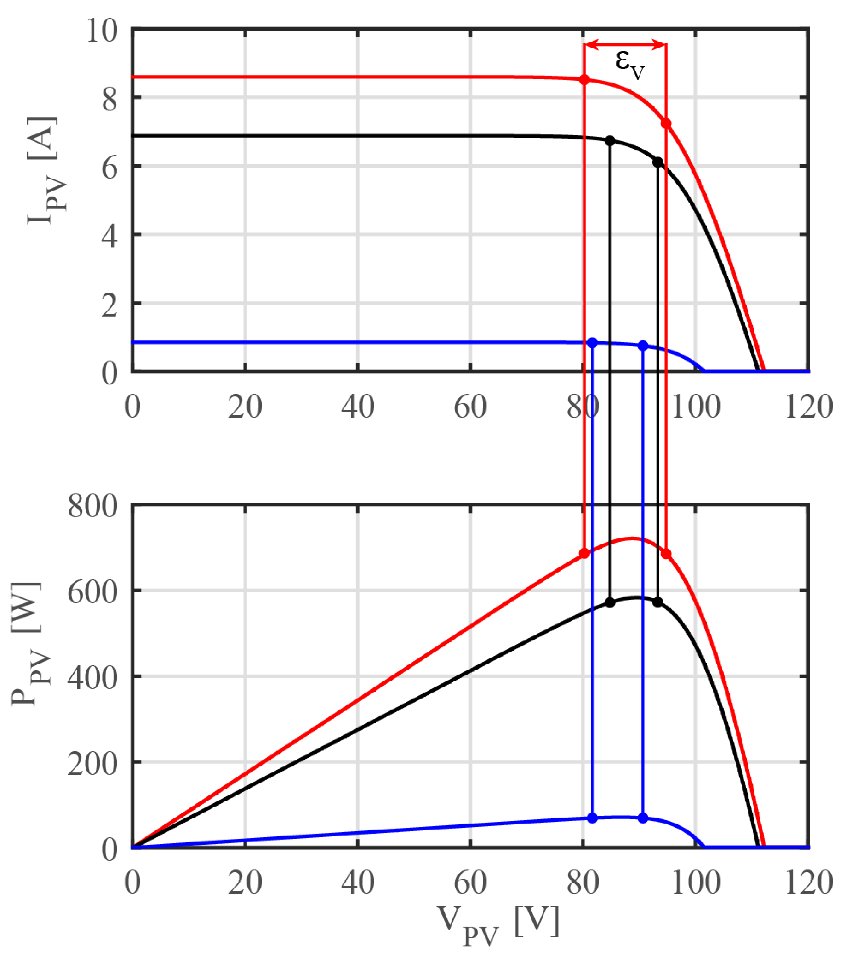
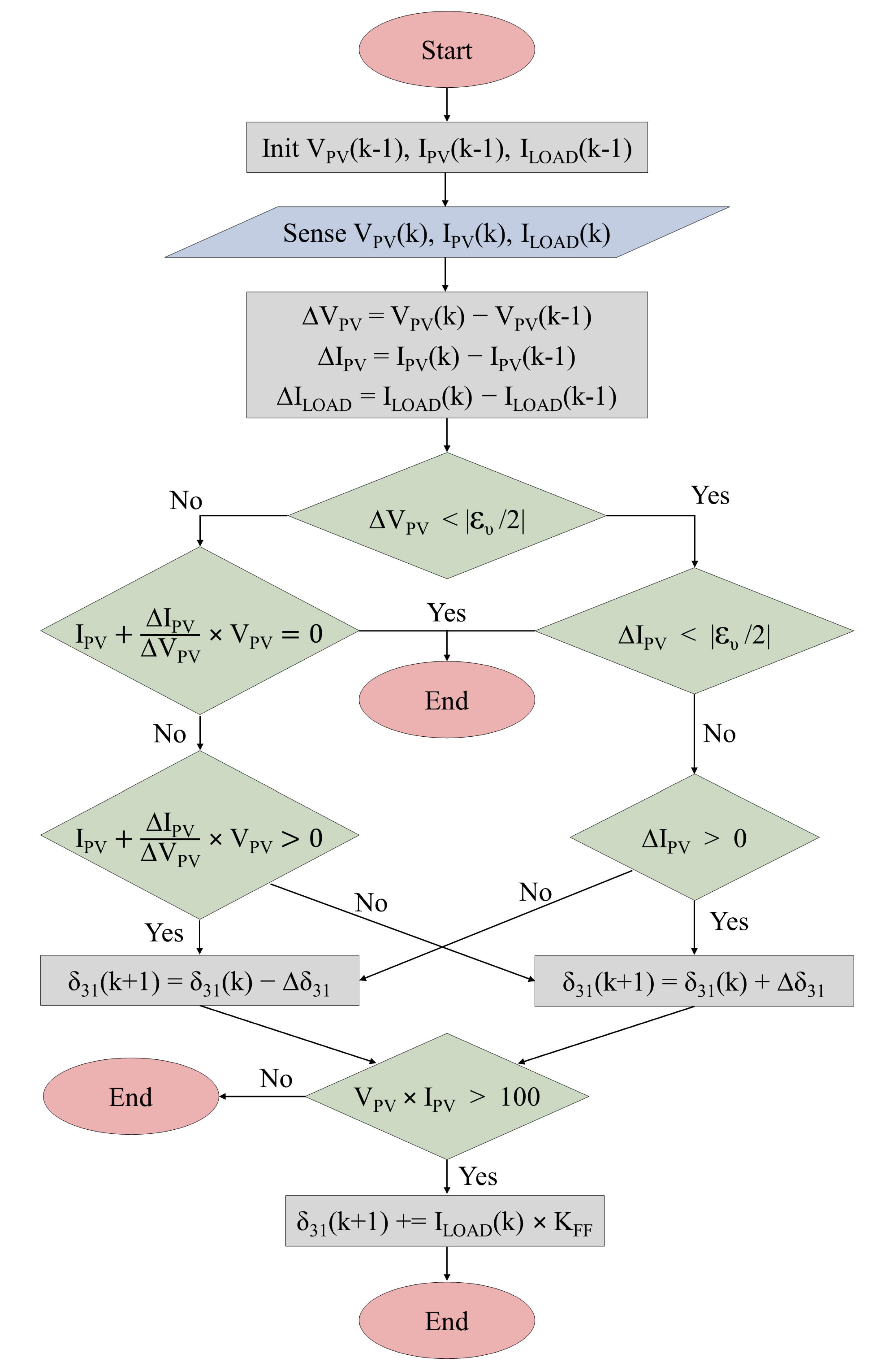
For the MPPT control loop, the incremental conductance algorithm has been used with an additional feed-forward. The algorithm control time has been settled to 1 ms, which is enough for a good MPPT without affecting the bus voltage control loop. The algorithm path determines if δ 13 must increase or decrease by the 1 × 10 4 incremental constant. With steady load conditions and a step change in solar irradiance from 0 to 1000 W/m 2 , the MPP is reached within about 1 s, which can be considered enough to follow the irradiance dynamics without a ripple. In fact, the algorithm has been chosen for small perturbation of the control signal when MPP is achieved. This means that in theory, when the voltage is exactly the V M P P , the phase shift is kept constant. Thus, in practice, a small error has to be included. Considering a 40 MHz microcontroller timer frequency, 400 counter periods must be defined to achieve the 100 kHz PWM frequency. Therefore, the resolution of the phase shift over half of the PWM period is 1/200. The power transfer control resolution can be divided in a non-linear way over the possible phase shift steps. From Equations (1)–(3), the worst error would be when the MPP corresponds to low phase shift values where the power transfer relation slope is higher. In Figure 8, the error is defined around the MPPs. The related simulation (same as Figure 9) considers solar irradiation of 1000 W/m 2 and zero power transfer to the bus. In this case, a δ 13 change from 0 to 0.005 shows the maximum possible error E V of 8 V.
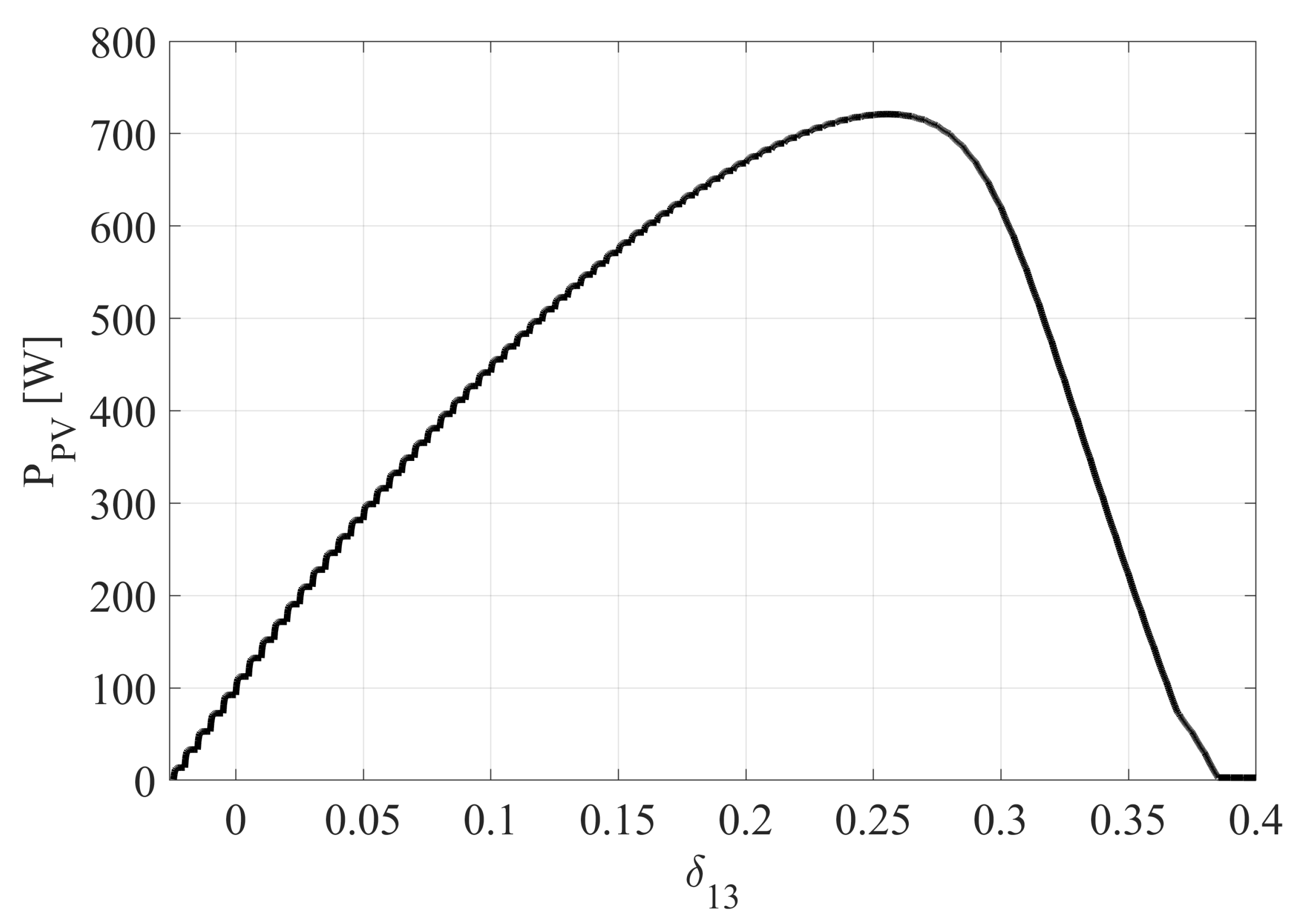
It has to be specified that for the power flow from PV to bus or battery, the theoretical relation shown in Equation (1) has to be used carefully, because of the PV panel voltage dependence. Figure 9 shows the power transfer between PV and battery without load and with maximum irradiation is shown. It is clear that δ 13 should not be greater than 0.25 to achieve maximum power flow. If we consider also a PV to bus power transfer, the maximum value of δ 13 used for the TAB control will be even lower.
In case of load variations, the current feed-forward is used for both keeping the MPP and constant bus voltage with a low ripple. This feed-forward acts therefore on both phase shifts as a power flow decoupling system. In a first approximation, considering the case of PV power availability (shining sun), the voltage of the PV module can be considered almost constant with respect to the fast load change and the aim of the feed-forward should be to keep a constant power flow between the PV array and both bus and battery. We can calculate d P P V = 0 from (14):
P P V = K 1 δ 12 ( 1 | δ 12 | ) + K 2 δ 13 ( 1 | δ 13 | ) = K 1 δ 12 ( 1 | δ 12 | ) + K 2 δ 13 ( 1 | δ 13 | ) = P P V .
We could observe the relation between load power derivative and phase shifts derivatives in order to adequate the control reaction from the following equations:
P L O A D = K 1 δ 12 ( 1 | δ 12 | ) + K 3 ( δ 12 δ 13 ) ( 1 | δ 12 δ 13 | ) ,
P L O A D δ 12 = K 1 ( 1 | δ 12 | ) K 1 δ 12 2 | δ 12 | K 3 ( δ 12 δ 13 ) 2 | δ 12 δ 13 | K 3 | δ 12 δ 13 | + K 3 ,
P L O A D δ 13 = K 3 ( δ 12 δ 13 ) 2 | δ 12 δ 13 | + K 3 | δ 12 δ 13 | K 3 ,
P L O A D δ 12 = V b u s δ 12 × I L O A D + I L O A D δ 12 × V b u s = 0 + I L O A D δ 12 × V b u s ,
where
K 1 = V P V V b u s 2 f s L 12 ,
K 2 = V P V V B A T 2 f s L 13 ,
K 3 = V B A T V b u s 2 f s L 23 .
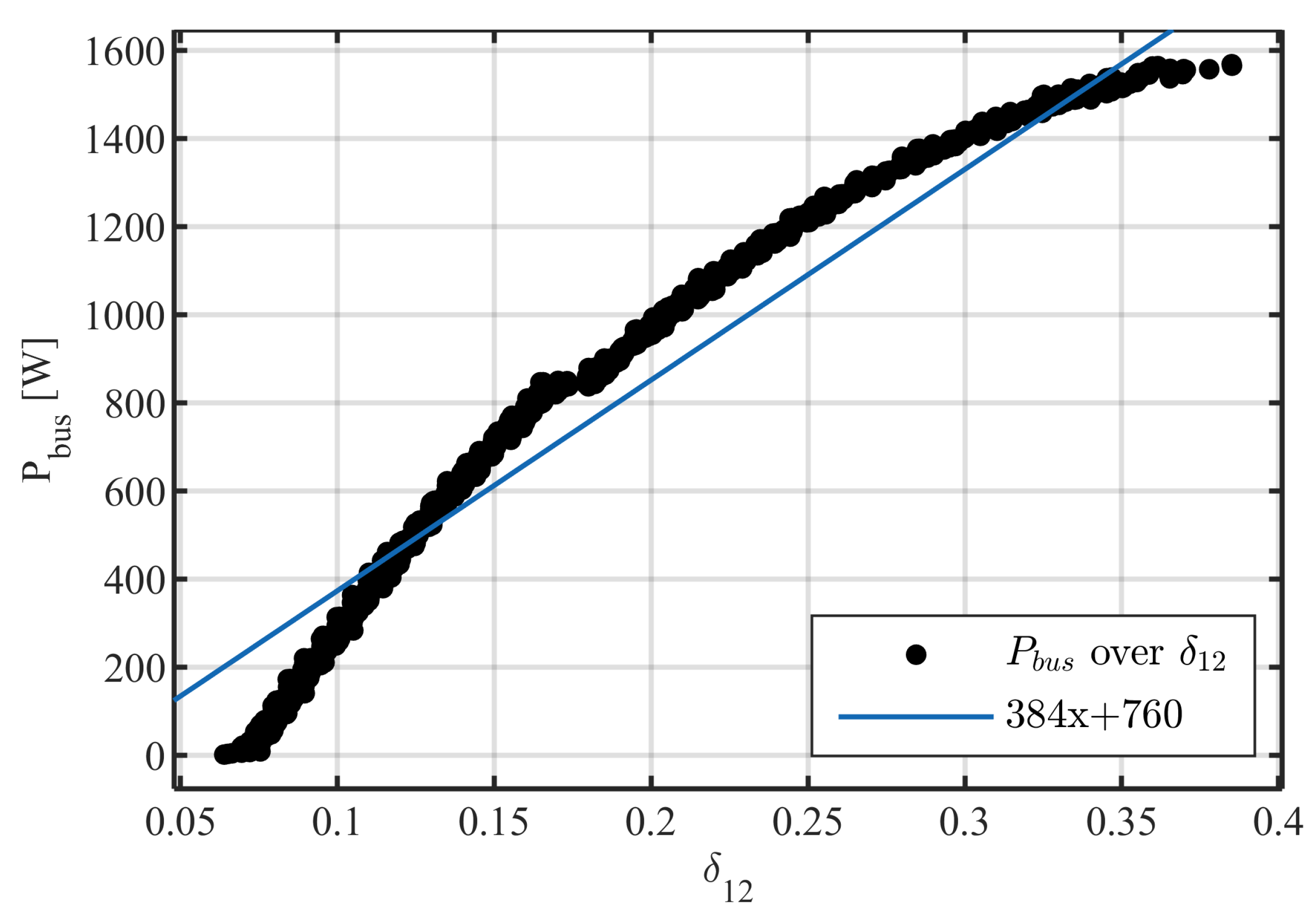
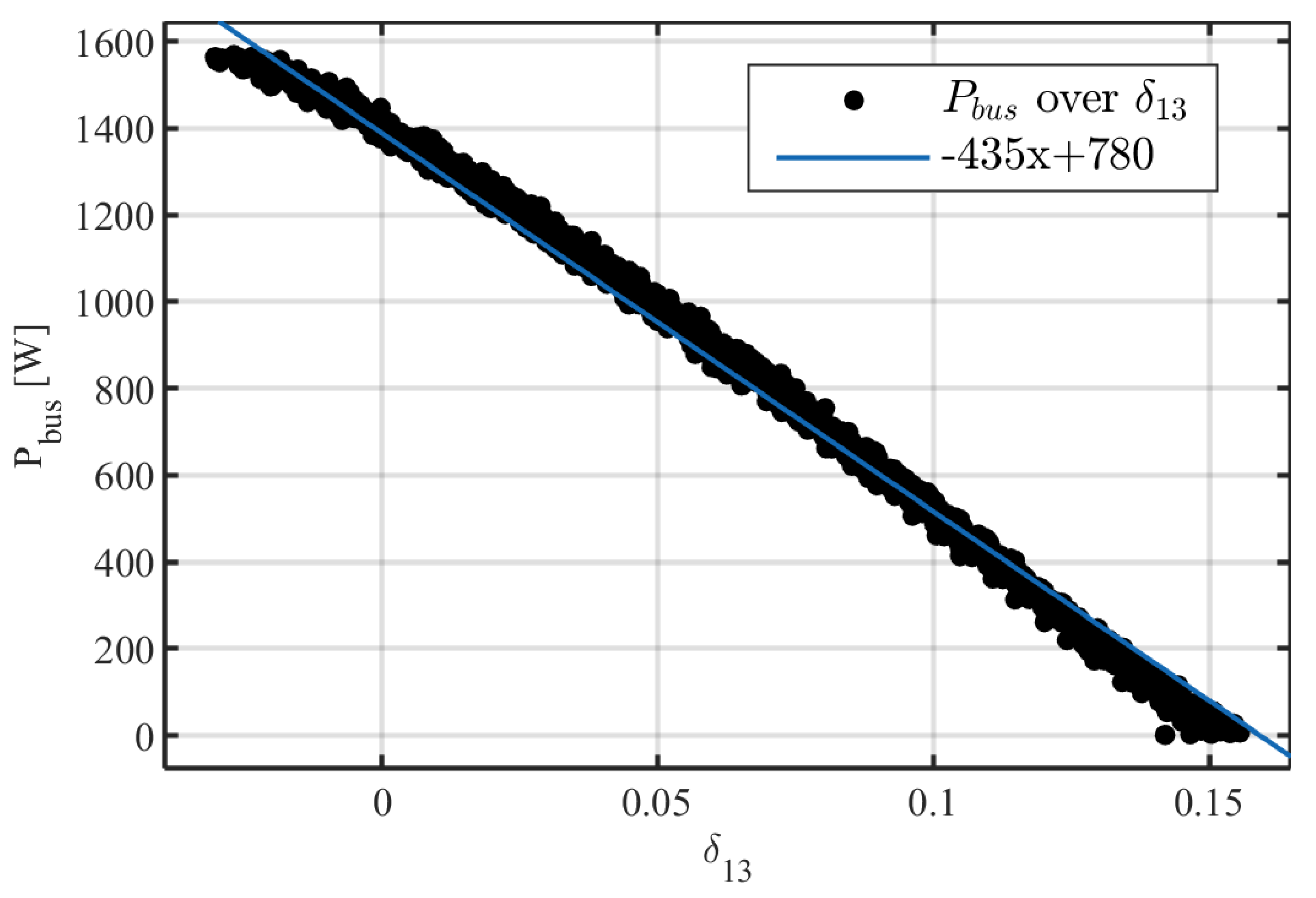
From the Equations (17) and (18), the correlation between the load current derivative and both phase shifts can be analyzed. Thus, these relations can be validated only considering the PV array as a voltage source, which is not. For this reason, the feed-forward parameters can be extracted observing the relation between P L O A D and both δ 12 and δ 13 with constant irradiation. Figure 10 and Figure 11 show the power to phase shift relations applying a slow and constant current load ramp from 0 to 32 A. In this simulation, the MPPT algorithm and bus control loop are applied without any feed-forward. These results have been obtained with an irradiation of 800 W/m 2 . Same simulations have been carried out with different irradiation values. With 1000 W/m 2 , the slope is slightly different, while at very low irradiation values, such as 200 W/m 2 , the algorithm should avoid a feed-forward which would result in a too high phase shift change. This is due to a higher power transfer gain obtained by the higher voltage on the PV modules, which at the same time reduces the power to load transfer slopes in relation to phase shifts.
Therefore, the MPPT control loop cycles have been defined as shown in the flow chart of Figure 12.

5. Simulated Model

The proposed architecture has been simulated with MATLAB Simulink on an OPAL Real Time simulator (Hardware platform OP4510, OPAL-RT Technologies, Inc., Montreal, QC, Canada), dividing the model into two subsystems. The electrical model of the TAB, shown in Figure 13, and the control subsystem.
Parasitic elements have been added for an overall efficiency estimation and second-order effects evaluation. Equivalent series resistances have been chosen as 10 m Ω , equivalent series inductances as 1 nH. The simulation parameters are shown in Table 2. A simulation step of 25 ns has been chosen in order to have enough resolution for the power transfer control. In fact, considering the relation between phase shift and power transfer between two ports, the control resolution is up to 0.01 p.u. normalized over the power transfer in the worst case.
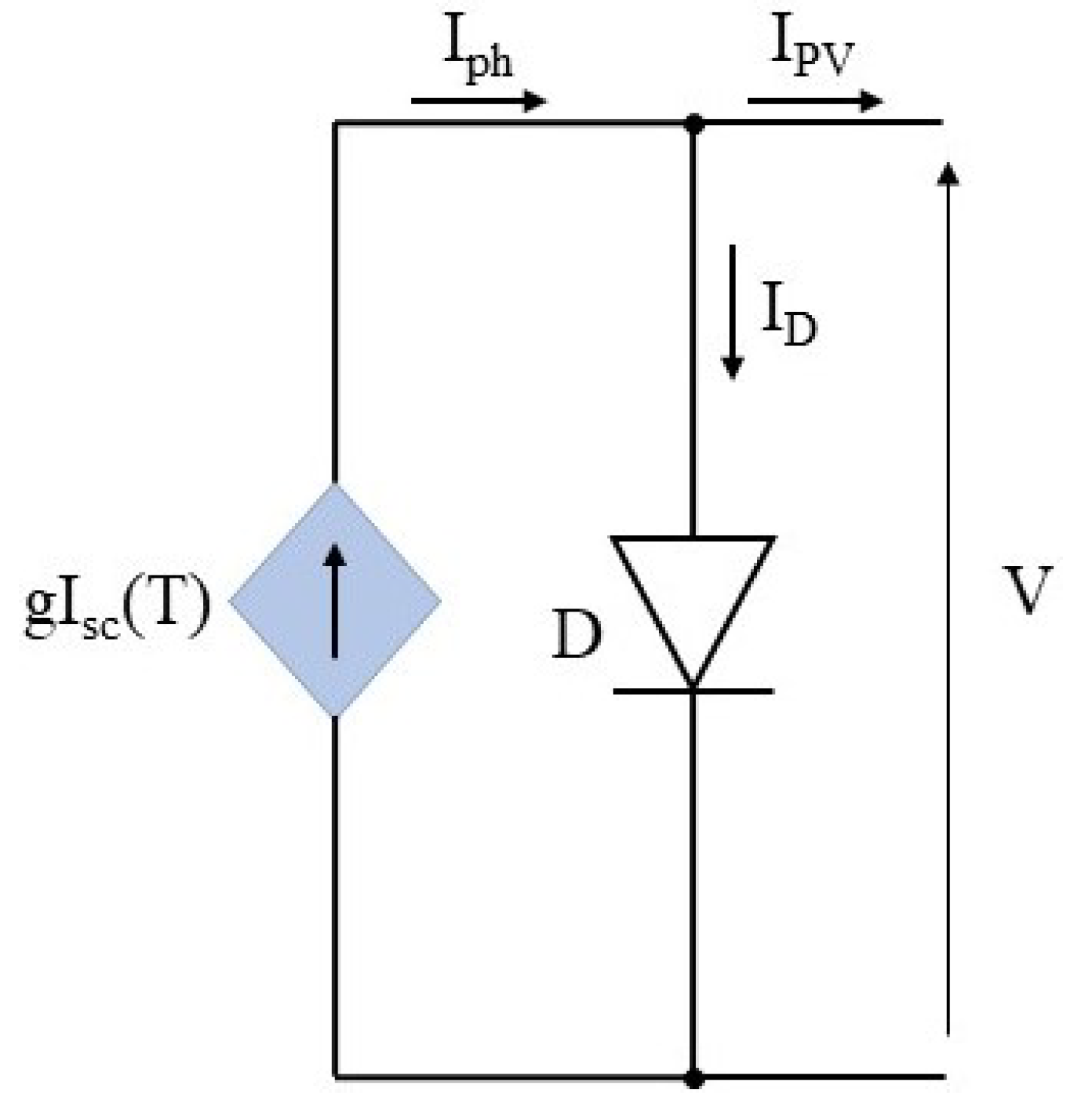
The PV model is a current-controlled source. The photovoltaic mathematical expressions are based on the equivalent circuit of a single diode model (Figure 14).
The following expressions are implemented in MATLAB/Simulink [25]:
I P V = I p h I D ,
where
I D = I s ( e q V k B A T 1 ) ,
I p h = g S T C [ I s c , S T C + K T i ( T T S T C ) ] ,
V = V P V + I P V R s ,
g S T C = G G S T C ,
I p h is the photo-generated current, I D is the PV dark current, I s is the reverse saturation current, q is the electron charge, k B is the Boltzmann’s constant, A is the diode ideality factor, T is the temperature, g S T C is the normalized solar irradiance, I s c , S T C is the short circuit current at Standard Test Conditions (STC), K T i is the temperature coefficient of the short circuit current I s c , T S T C is the reference temperature (298.15 K), R s is the PV series resistance, G is the solar irradiance and G S T C is 1000 W/m 2 .
The saturation current I s depends on the short circuit current I s c and on the open circuit voltage V o c of the PV module. In this case, we consider PV modules with monocrystalline silicon cells. Therefore, I s can be described with the following expression [26]:
I s = I s , S T C · ( T T S T C ) 3 · e q ϵ G k B A ( 1 T S T C 1 T ) ,
where I s , S T C is the reverse saturation current at STC, ϵ G is the material band gap energy (eV), K T v is the temperature coefficient of the open circuit voltage V o c .
The battery model is based on the same principle, controlling a voltage source as defined from [27]:
V B A T = E 0 K · Q Q i t + A · e B · i t ,
where
i t = Q + I B A T ,
and E 0 is a constant voltage, K is the polarization constant, Q is the maximum battery capacity, A is the exponential voltage, B is the exponential capacity.
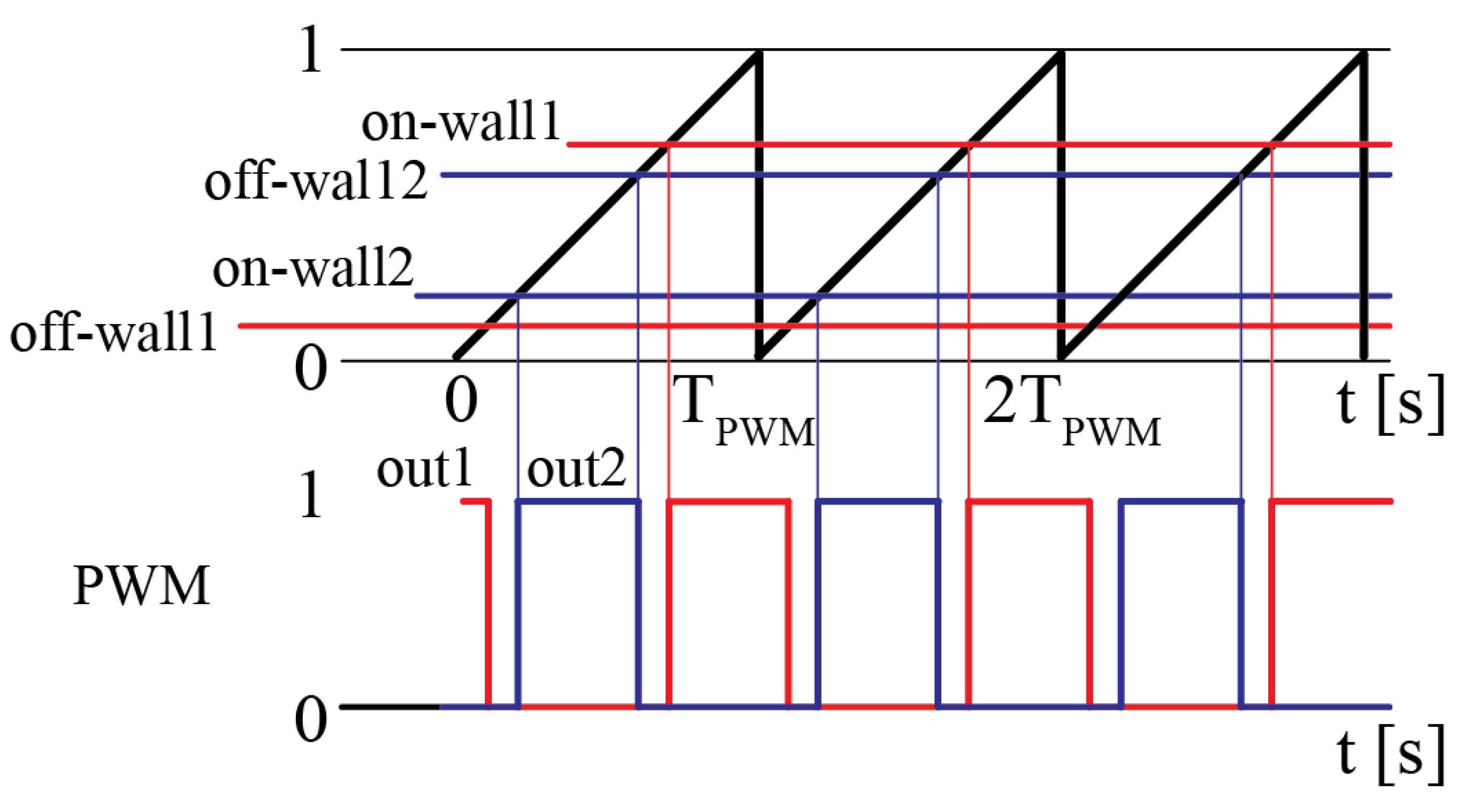
Asymmetric PWMs are generated with a sawtooth reference wave, compared with an offset signal to obtain the required phase shifts and a duty-cycle signal in order to eventually reduce the half periods below 50% (or to add a dead time). The flow chart of the asymmetric PWM generation algorithm is shown in Figure 15. In Figure 16 an example is shown with an offset of 0.2 and a duty-cycle of 0.4. The two outputs are sent directly to the four switches of the full bridges in order to obtain the desired transformer voltages.

6. Model Validation with Early Experimental Results

Early tests have been carried out with the aim to validate the simulated model under certain conditions. As reference, we took the transformer voltages and currents, and the power transfer from one port to the load. For this purpose, PV modules and batteries can be replaced with DC generators connected to the first and second ports. Although a DC voltage generator does not model a PV module, this choice is taken to simplify the tuning of the control parameters on V b u s side. In this way, MPPT parameters are separated from V b u s control loop parameters. This setup allows only to transfer power from the PV and battery port to the load connected on the third port. Nevertheless, voltages and currents on the transformer can be compared with those of the simulation. Figure 17 shows the laboratory prototype of the TAB converter based on 6 development boards [28] with TPH3212PS GaN transistors by Transphorm ( V d s = 650 V, I d = 27 A, R o n = 72 m Ω ).
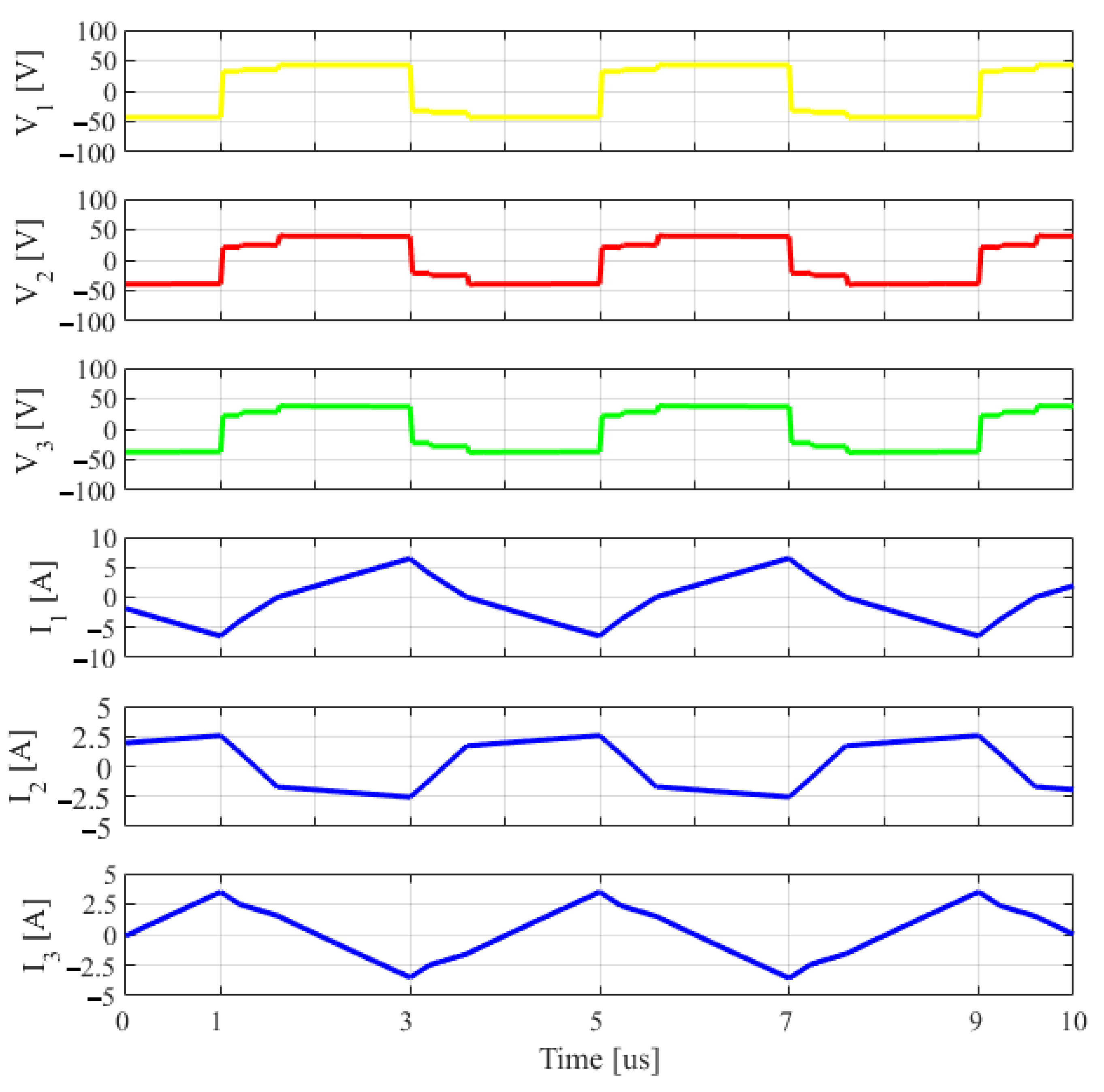
The first experimental results have been compared to the simulated model looking at the currents and voltages on the TAB transformer in order to validate the model at the transistor level. In Figure 18 the transformer voltages V 1 , V 2 , V 3 and the currents I 1 , I 2 , I 3 are shown applying the voltages V P V = 50 V, V B A T = 12 V, the load R L O A D = 20 Ω and the phase shifts δ 12 = 0.15 and δ 13 = 0.05. The simulation results in the same conditions are shown in Figure 19. The comparison shows a good match, proving the reliability of simulations carried on the same model at different working conditions.
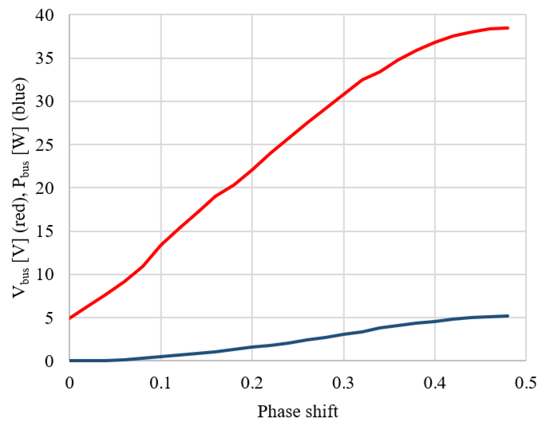
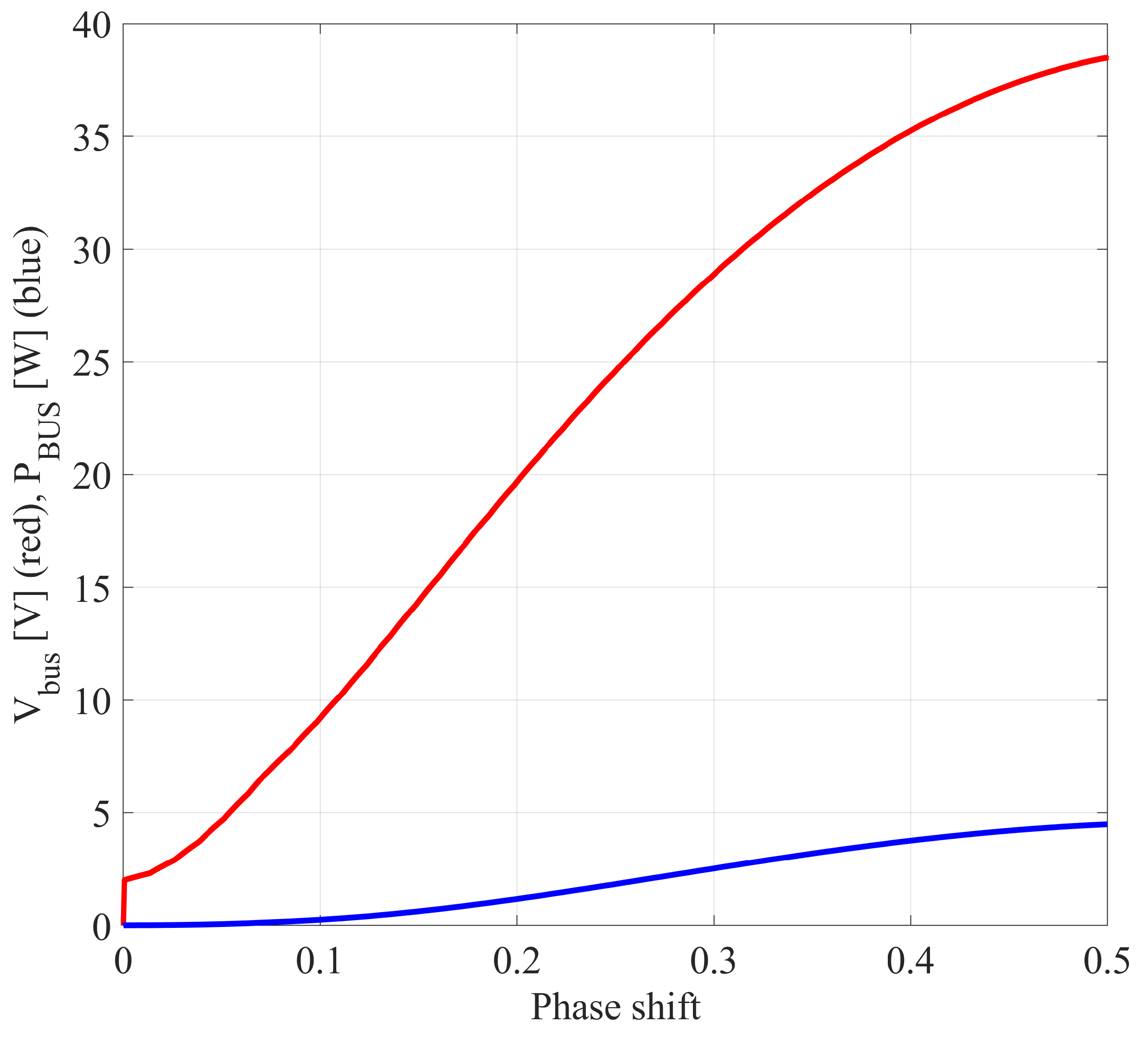
A second test has been done applying a sweep to δ 12 from 0 to 0.48, fixing δ 13 to 0, with a V P V of 10 V, V b a t = 0 V and a load R L O A D of 330 Ω . Figure 20 shows the experimental results, while Figure 21 the simulation results with same conditions. The measurements are in good agreement both with the numerical model and the approximated theoretical power transfer relation (1).

7. Simulation Results and Discussion

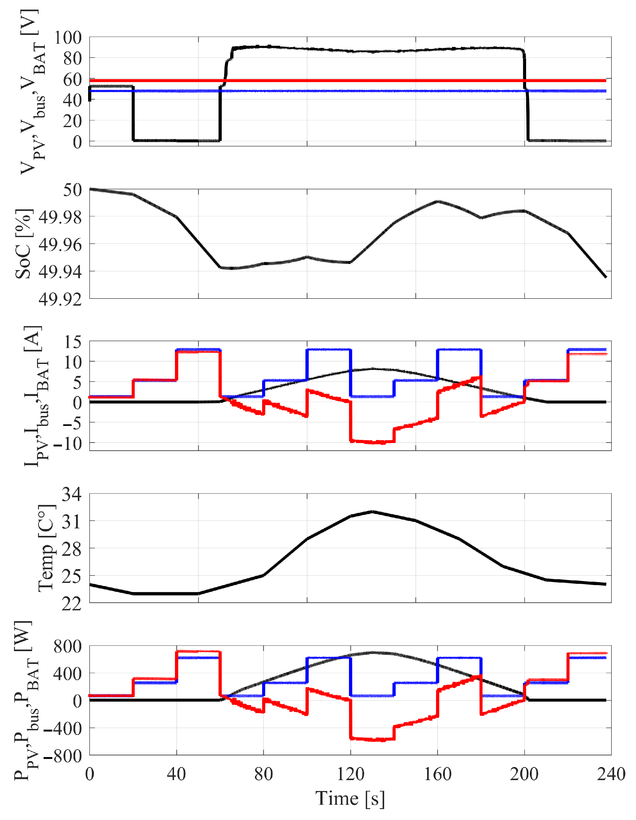
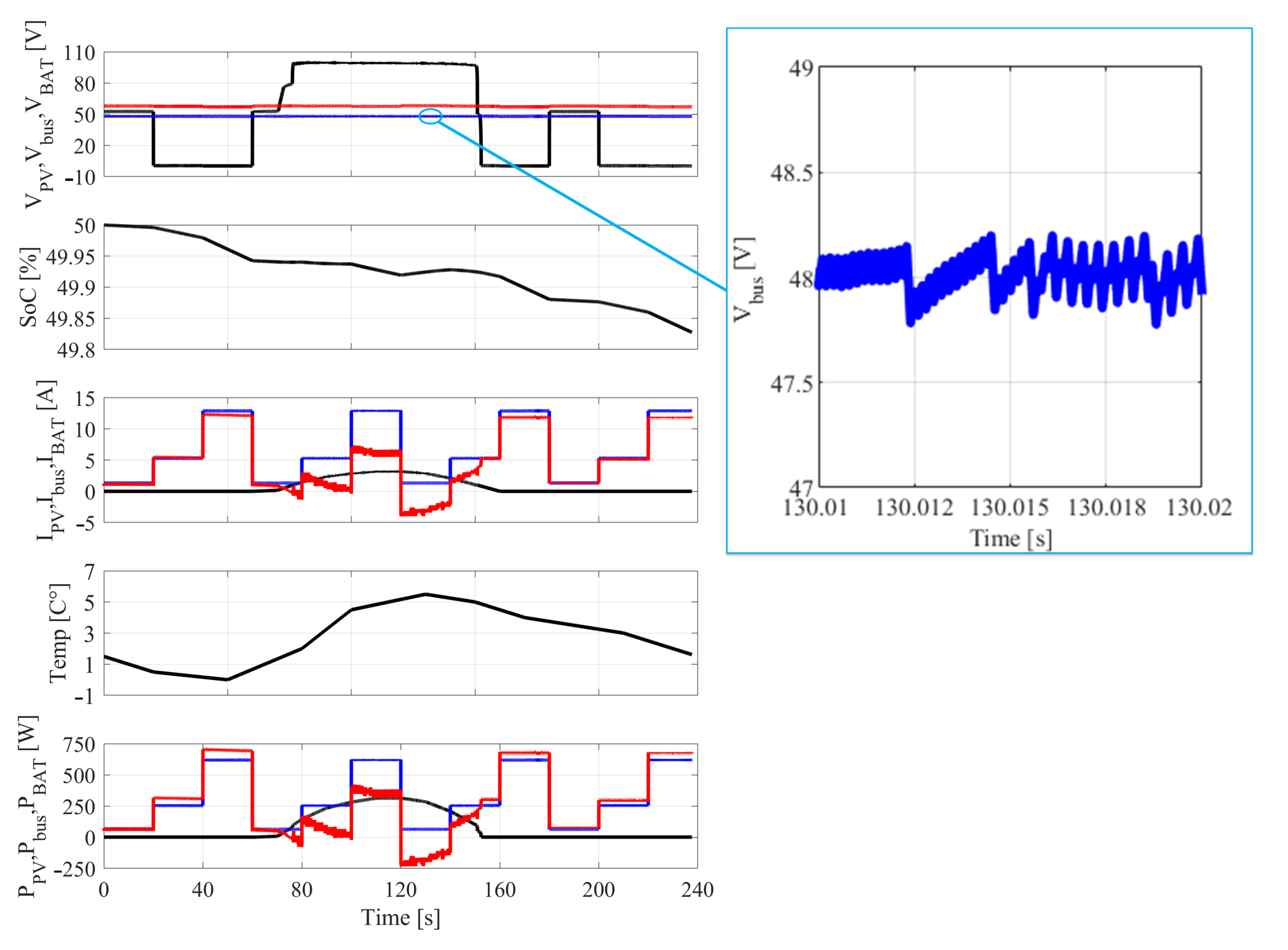
Different simulations have been executed to validate the control strategy. Figure 22 and Figure 23 show the results of a one-day irradiation profile, compressed in 240 s, with both winter and summer irradiation and temperature conditions. The results show a low ripple on V b u s (blue), below 0.5 V, applying three load power profiles P b u s of 64 W, 256 W, 620 W (blue), changing every 20 s. The fast load current I b u s (blue) changes are supplied with the battery current I B A T (red), maintaining the PV current I P V (black) on the MPP. V P V (black) is 0 V when the irradiation is 0 W/m 2 and the capacitor C P V is discharged.
Starting with an SoC of 50%, the battery has been slightly discharged with summer conditions, and more heavily with winter ones. In both simulations, the MPP is followed over the whole time, taking full advantage of the PV array available power.
Considering the model accuracy and the small simulation step of 25 ns, the time needed for the 240 s of simulations was about 8 h with the OPAL Real Time simulator set in simulation mode.
It can be noticed that in the case of low irradiation and heavy load, the power losses are higher and the TAB efficiency is reduced. This is due to the general increase of losses with a high load factor and a low distributed ratio between the ports [29]. To be considered is that a disadvantage of the TAB consists in the reactive currents, always present in the ports also without power transfer [30].

8. Conclusions

Interfacing a PV array to the TAB is not a trivial task due to the complexity and numerous degrees of freedom. Compared to the state of the art, in this work, the PV panels are not interfaced through dedicated MPPT converters but directly to one of the three ports of the TAB. On the other ports, battery and load are directly connected as well. These simulations need a combined methodology of analytic analysis and several simulation comparisons. A critical point of the TAB is the difficulty of integrating the classical theoretical two-port analysis, not perfectly suitable for the proposed architecture. Nevertheless, it is possible to achieve a good MPPT over a wide operating area, maintaining a fast and reliable bus voltage control.
Many aspects of the TAB have been analyzed and a simple but effective control strategy has been explored, without matrix calculations. The instructions to be implemented can be considered the three voltage and current sensing, the proportional-integral calculations for the bus voltage control, the load current feed-forward, the MPPT algorithm. The firmware needed for the proposed control can be implemented on a general-purpose 32 bit microcontroller.
Accurate models of the TAB, PV modules and battery have been developed for reliable step response and fast load current changes. A real-time simulator has been used with a 25 ns simulation step in order to approach real behavior conditions, obtaining useful results in a reasonable time. The TAB power flow equations have been analyzed and algebraic calculations have been used for the control loop definition. The model has been validated through early experimental results. More experimental at nominal power rates are the subject of future works. Finally, different operating conditions have been simulated and the usefulness of the architecture has been proved.
Considering an adequate sizing of the PV array and battery, in relation to the power required, the proposed architecture shows an alternative to the existing self-sufficient systems, interesting for grid-islanded architectures such as MEA with solar panels, ships or residential applications.

Author Contributions

Conceptualization, I.K., A.T. and N.D.; Formal analysis, D.S.; Investigation, D.S. and A.T.; Methodology, C.C. and P.C.; Project administration, N.D.; Resources, I.K.; Supervision, N.D.; Writing—original draft, D.S.; Writing—review and editing, I.K., A.T., C.C., P.C. and N.D. All authors have read and agreed to the published version of the manuscript.

Funding

This research received no external funding.

Conflicts of Interest

The authors declare no conflict of interest.

References

  1. Boroyevich, D.; Cvetković, I.; Dong, D.; Burgos, R.; Wang, F.; Lee, F. Future electronic power distribution systems—A contemplative view. In Proceedings of the International Conference on Optimisation of Electrical and Electronic Equipment, Brasov, Romania, 20–22 May 2010. [Google Scholar]
  2. Goikoetxea, A.; Canales, J.M.; Sanchez, R.; Zumeta, P. DC versus AC in residential buildings: Efficiency comparison. In Proceedings of the International Conference IEEE EuroCon 2013, Zagreb, Croatia, 1–4 July 2013. [Google Scholar]
  3. Burmester, D.; Rayudu, R.; Seah, W.; Akinyele, D. A review of nanogrid topologies and technologies. Renew. Sustain. Energy Rev. 2017, 67, 760–775. [Google Scholar] [CrossRef]
  4. Yu, Y.; Wada, K.; Masumoto, K.; Kado, Y. A DC power distribution system In a data center using a triple active bridge DC-DC converter. IEEJ J. Ind. Appl. 2018, 7, 202–209. [Google Scholar] [CrossRef] [Green Version]
  5. Liu, R.; Xu, L.; Kang, Y.; Hui, Y.; Li, Y. Decoupled TAB converter with energy storage system for HVDC power system of more electric aircraft. J. Eng. 2018, 13, 593–602. [Google Scholar] [CrossRef]
  6. Wang, Z.; Castellazzi, A. SiC-based Triple Active Bridge Converter for Shipboard Micro-grid Applications with Efficient Energy Storage. In Proceedings of the 6th IEEE International Conference on Smart Grid icSmartGrids, Nagasaki, Japan, 4–6 December 2018. [Google Scholar]
  7. Giuliani, F.; Buticchi, G.; Liserre, M.; Delmonte, N.; Cova, P.; Pignoloni, N. GaN-based Triple Active Bridge for Avionic Application. In Proceedings of the 2017 IEEE 26th International Symposium on Industrial Electronics (ISIE), Edinburgh, UK, 19–21 June 2017. [Google Scholar]
  8. Michon, M.; Duarte, J.L.; Hendrix, M.; Simões, M.G. A three-port bi-directional converter for hybrid fuel cell systems. In Proceedings of the International Conference PESC Record—IEEE Annual Power Electronics Specialists Conference, Aachen, Germany, 20–25 June 2004. [Google Scholar]
  9. Duarte, J.L.; Hendrix, M.; Simões, M.G. Three-port bidirectional converter for hybrid fuel cell systems. IEEE Trans. Power Electron. 2007, 22, 480–487. [Google Scholar] [CrossRef] [Green Version]
  10. Zou, S.; Lu, J.; Khaligh, A. Modelling and control of a triple-activebridge converter. IET Power Electron. 2020, 13, 961–969. [Google Scholar] [CrossRef]
  11. Dos Santos, W.M.; Marcon, R.C.; Martins, D.C. Application of the voltage fed TAB converter as energy source coupler. IEEE Lat. Am. Trans. 2011, 9, 510–515. [Google Scholar] [CrossRef]
  12. Chattopadhyay, R.; Acharya, S.; Gohil, G.; Bhattacharya, S. One switching cycle current control strategy for Triple Active Bridge phaseshifted DC-DC converter. In Proceedings of the 2017 IEEE Industry Applications Society Annual Meeting, Cincinnati, OH, USA, 1–5 October 2017; pp. 1–8. [Google Scholar]
  13. Zhao, C.; Round, S.D.; Kolar, J.W. An isolated three-port bidirectional dc-dc converter with decoupled power flow management. IEEE Trans. Power Electron. 2008, 23, 2443–2453. [Google Scholar] [CrossRef]
  14. Ilango, S.; Viju Nair, R.; Chattopadhyay, R.; Bhattacharya, S. Photovoltaic and energy storage grid integration with fully modular architecture using triple port active bridges and cascaded H-bridge inverter. In Proceedings of the IECON 2018—44th Annual Conference of the IEEE Industrial Electronics Society, Washington, DC, USA, 21–23 October 2018. [Google Scholar]
  15. Nair, R.V.; Gulur, S.; Chattopadhyay, R.; Beddingfield, R.; Mathur, S.; Bhattacharya, S.; Gohil, G.; Ohodnicki, P. Large Scale Grid Integration of Photovoltaic and Energy Storage Systems Using Triple Port Dual Active Bridge Converter Modules. In Proceedings of the International Conference IEEE Power and Energy Society General Meeting, Portland, OR, USA, 5–10 August 2018. [Google Scholar]
  16. Chao, K.H.; Huang, C.H. Bidirectional DC-DC soft-switching converter for stand-alone photovoltaic power generation systems. IET Power Electron. 2014, 7, 1557–1765. [Google Scholar] [CrossRef]
  17. Delmonte, N.; Cova, P.; Santoro, D.; Toscani, A. Development of a GaN based triple-active-bridge for DC nanogrid. In Proceedings of the 20th European Conference on Power Electronics and Applications, EPE 2018 ECCE Europe, Riga, Latvia, 17–21 September 2018. [Google Scholar]
  18. De Doncker, R.W.; Divan, D.M.; Kheraluwala, M.H. A Three-Phase Soft-Switched High-Power-Density DC/DC Converter for High-Power Applications. IEEE Trans. Ind. Appl. 1991, 27, 63–73. [Google Scholar] [CrossRef]
  19. Pham, V.L.; Wada, K. Design of Series Inductances in Triple Active Bridge Converter Using Normalization Procedure for Integrated EV and PV System. In Proceedings of the ICPE 2019—ECCE Asia-10th International Conference on Power Electronics, Bexco, Busan, Korea, 27–30 May 2019. [Google Scholar]
  20. Tao, H.; Duarte, J.L.; Hendrix, M.A. Three-port triple-half-bridge bidirectional converter with zero-voltage switching. IEEE Trans. Power Electron. 2008, 23, 782–792. [Google Scholar]
  21. Luo, S.; Wu, F.; Wang, G. Improved TPS control for DAB DC-DC converter to eliminate dual-side flow back currents. IET Power Electron. 2020, 13, 32–39. [Google Scholar] [CrossRef]
  22. Wang, L.; Wang, Z.; Li, H. Asymmetrical duty cycle control and decoupled power flow design of a three-port bidirectional DC-DC converter for fuel cell vehicle application. IEEE Trans. Power Electron. 2012, 27, 891–904. [Google Scholar] [CrossRef]
  23. Sim, J.; Lee, J.; Choi, H.; Jung, J.-H. High Power Density Bidirectional Three-port DC-DC Converter for Battery Applications in DC microgrids. In Proceedings of the ICPE 2019—ECCE Asia—10th International Conference on Power Electronics, Bexco, Busan, Korea, 27–30 May 2019. [Google Scholar]
  24. Yang, J.; Buticchi, G.; Gu, C.; Gunter, S.; Yan, H.; Wheeler, P. Transfer Function Based Input Impedance Determination of Triple Active Bridge Converter. In Proceedings of the ECON 2019—45th Annual Conference of the IEEE Industrial Electronics Society, Lisbon, Portugal, 14–17 October 2019. [Google Scholar]
  25. Mahmoud, Y.; El-Saadany, E. Accuracy improvement of the ideal PV Model. IEEE Trans. Sustain. Energy 2015, 6, 909–911. [Google Scholar] [CrossRef]
  26. Elkholy, A.; Abou El-Ela, A.A. Optimal parameters estimation and modelling of photovoltaic modules using analytical method. Heliyon 2019, 5, 7. [Google Scholar] [CrossRef] [PubMed]
  27. Carter, R.; Cruden, A.; Hall, P.J.; Zaher, A.S. An improved lead-acid battery pack model for use in power simulations of electric vehicles. IEEE Trans. Energy Convers. 2012, 27, 21–28. [Google Scholar] [CrossRef]
  28. Transphorm. TDHBG2500P100: 2.5kW Half-bridge Evaluation Board. User Guide. 2017. Available online: https://www.transphormusa.com/en/document/tdhbg2500p100-user-guide/ (accessed on 1 March 2021).
  29. Kado, Y.; Katagiri, K. Autonomous Distributed Power Network Consisting of Triple Active Bridge Converters. In Proceedings of the International Conference Energy and Sustainability in Small Developing Economies, Funchal, Portugal, 9–12 July 2018. [Google Scholar]
  30. Katagiri, K.; Nakagawa, S.; Kado, Y. Analysis on Load-Factor Dependence of Triple Active Bridge Converter’s Transmission Efficiency for Autonomous Power Networks. In Proceedings of the International Conference IEEE Region 10 Conference (TENCON), Penang, Malaysia, 5–8 November 2017. [Google Scholar]
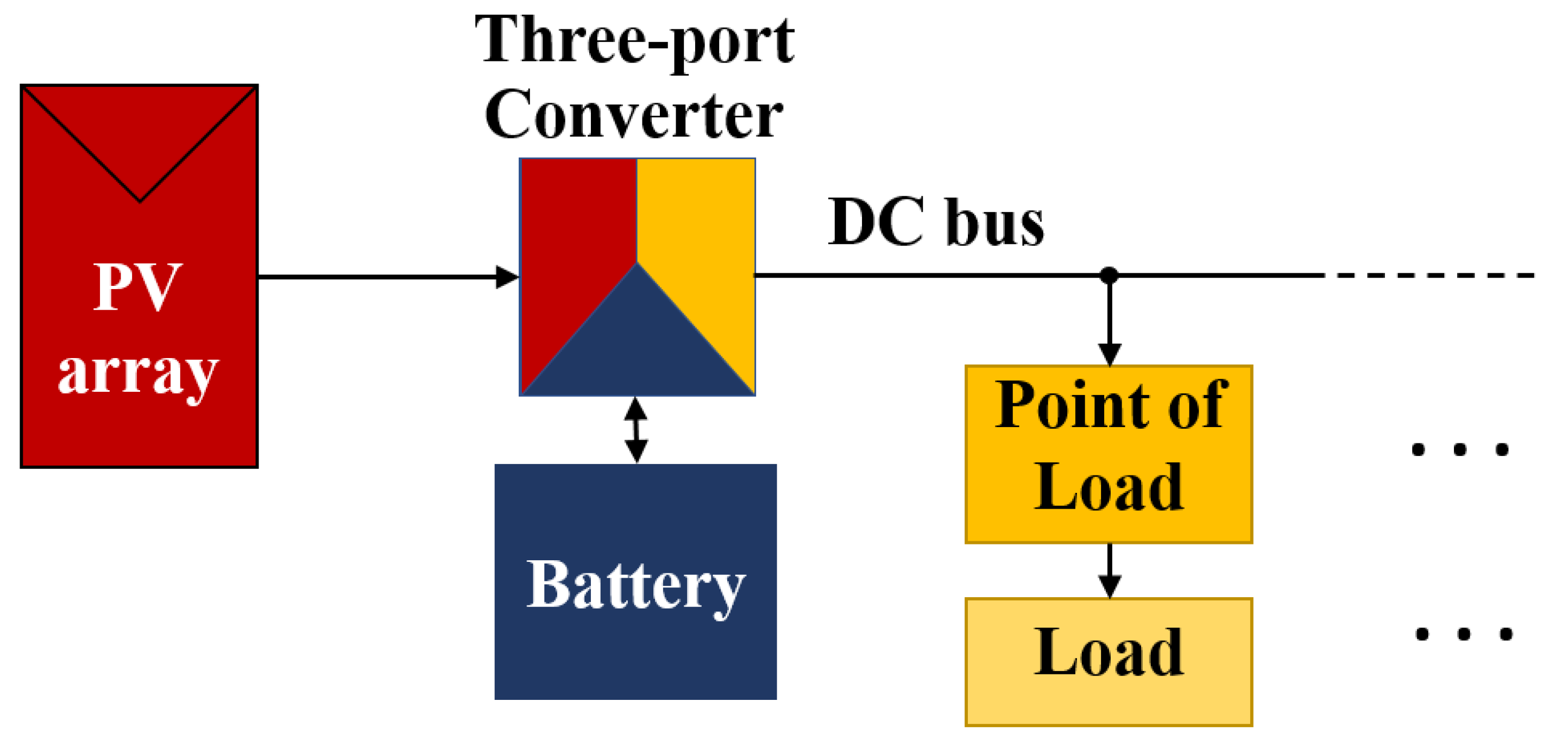
Figure 1. The islanded DC nanogrid considered.
Energies 14 02854 g001
Figure 2. (a) TAB circuit topology. (b) Δ -transformed equivalent model.
Energies 14 02854 g002
Figure 3. V b u s control architecture.
Energies 14 02854 g003
Figure 4. Voltage control step response estimated with SISOtool.
Energies 14 02854 g004
Figure 5. Simulation result with a bus voltage reference step change.
Energies 14 02854 g005
Figure 6. Voltage step rejection response estimated with SISOtool.
Energies 14 02854 g006
Figure 7. Simulation result with a load change from 36 to 9 Ω .
Energies 14 02854 g007
Figure 8. Error estimation on PV module I–V curve and P–V curve at different irradiation values @Tref.
Energies 14 02854 g008
Figure 9. Simulation results of the PV module power transfer in relation to the phase shift between the PV port and the battery port.
Energies 14 02854 g009
Figure 10. Power to load transfer over δ 12 , keeping MPPT.
Energies 14 02854 g010
Figure 11. Power to load transfer over δ 13 , keeping MPPT.
Energies 14 02854 g011
Figure 12. One control cycle MPPT algorithm flow chart.
Energies 14 02854 g012
Figure 13. Simulink electrical model.
Energies 14 02854 g013
Figure 14. Schematic of the PV model.
Energies 14 02854 g014
Figure 15. Asymmetric PWM generator algorithm flow chart.
Energies 14 02854 g015
Figure 16. Asymmetric PWM generation example.
Energies 14 02854 g016
Figure 17. Test bench for early experimental results.
Energies 14 02854 g017
Figure 18. Experimental results of the transformer voltages V 1 (yellow), V 2 (red), V 3 (green) and currents I 1 , I 2 and I 3 (blue), with V P V = 50 V, V B A T = 12 V, R L O A D = 20 Ω , δ 12 = 0.15 and δ 13 = 0.05. Settings of the oscilloscope are: 100 V/div for the voltages; 5 A/div for the currents; time base of 1 μs/div.
Energies 14 02854 g018
Figure 19. Simulation results of the transformer voltages V 1 (yellow), V 2 (red), V 3 (green) and currents I 1 , I 2 and I 3 (blue), with V P V = 50 V, V B A T = 12 V, R L O A D = 20 Ω , δ 12 = 0.15 and δ 13 = 0.05.
Energies 14 02854 g019
Figure 20. Experimental results of the voltage V b u s and the power P b u s versus one phase shift, with the other at zero constant value, V P V = 10 V, V b a t = 0 V and R L O A D = 330 Ω .
Energies 14 02854 g020
Figure 21. Simulation results of the voltage V b u s and the power P b u s versus one phase shift, with the other at zero constant value, V P V = 10 V, V b a t = 0 V and R L O A D = 330 Ω .
Energies 14 02854 g021
Figure 22. Simulation results in summer standard conditions for Parma, 44 45 53 N 10 18 26 E, Italy. V P V , I P V , P P V (black), V b u s , I b u s , P b u s (blue), V B A T , I B A T , P B A T (red), SoC, Temp.
Energies 14 02854 g022
Figure 23. Simulation results in winter standard conditions for Parma, 44 45 53 N 10 18 26 E, Italy. V P V , I P V , P P V (black), V b u s , I b u s , P b u s (blue), V B A T , I B A T , P B A T (red), SoC, Temperature. In the inset it is magnified a part of the DC bus voltage ripple.
Energies 14 02854 g023
Table 1. Architecture parameters.
(a) PV Parameters
Max P P V [W] V o c [V] I S C [A] C P V [ μ F]
721112.28.6470
(b) Bus parameters
Max P b u s [W] V b u s [V] C b u s [ μ F]
157048470
(c) Battery parameters
Capacity [Ah] V N O M [V] C B A T [ μ F] I M A X [A]
20048470450
(d) Transformer parameters
f s [kHz] n 1 : n 2 : n 3 L m [mH]
1001:1:10.2
L 1 [ μ H] L 2 [ μ H] L 3 [ μ H]
2.81.41.6
Table 2. Simulation parameters.
T s Simulation [ns] T s Control [μs] T s Control MPPT [ms]
251001
K F F Feed Forward δ 12 K p A δ 13 Step
2.6 × 10 3 6 × 10 3 1 × 10 4
K I Feed Forward δ 13 K i A
2.3 × 10 3 10
Publisher’s Note: MDPI stays neutral with regard to jurisdictional claims in published maps and institutional affiliations.