Effective Method for Diagnosing Continuous Welded Track Condition Based on Experimental Research
Abstract
:1. Introduction
2. Literature Review
- Average rail temperature ,
- Nominal rail temperature Ts—the most advantageous from the point of view of rail attachment to sleepers, with a value higher than the average temperature by 1–10 °C,
- The temperature of the rail lay Ty corresponding to the temperature of the rails after they have been unloaded and placed on the sleepers but before they are attached,
- Rail attachment temperature Tp and its range (Ts ± 3 °C),
- Neutral temperature Tn at which no thermal stresses occur in the rail.
- α—thermal expansion coefficient of the rail steel (1/°C),
- E—Young modulus of steel (MPa),
- ΔTp—temperature difference of the rail in relation to the neutral temperature (temperature at which there is no thermal stress in the rail) (°C).
- A—rail cross-section area (m2),
- Other symbols as in formula (1).
3. Description of the Method of Continuous Welded Track Condition Diagnosis Based on Experimental Tests (Measurements)
3.1. Assumptions of the Method
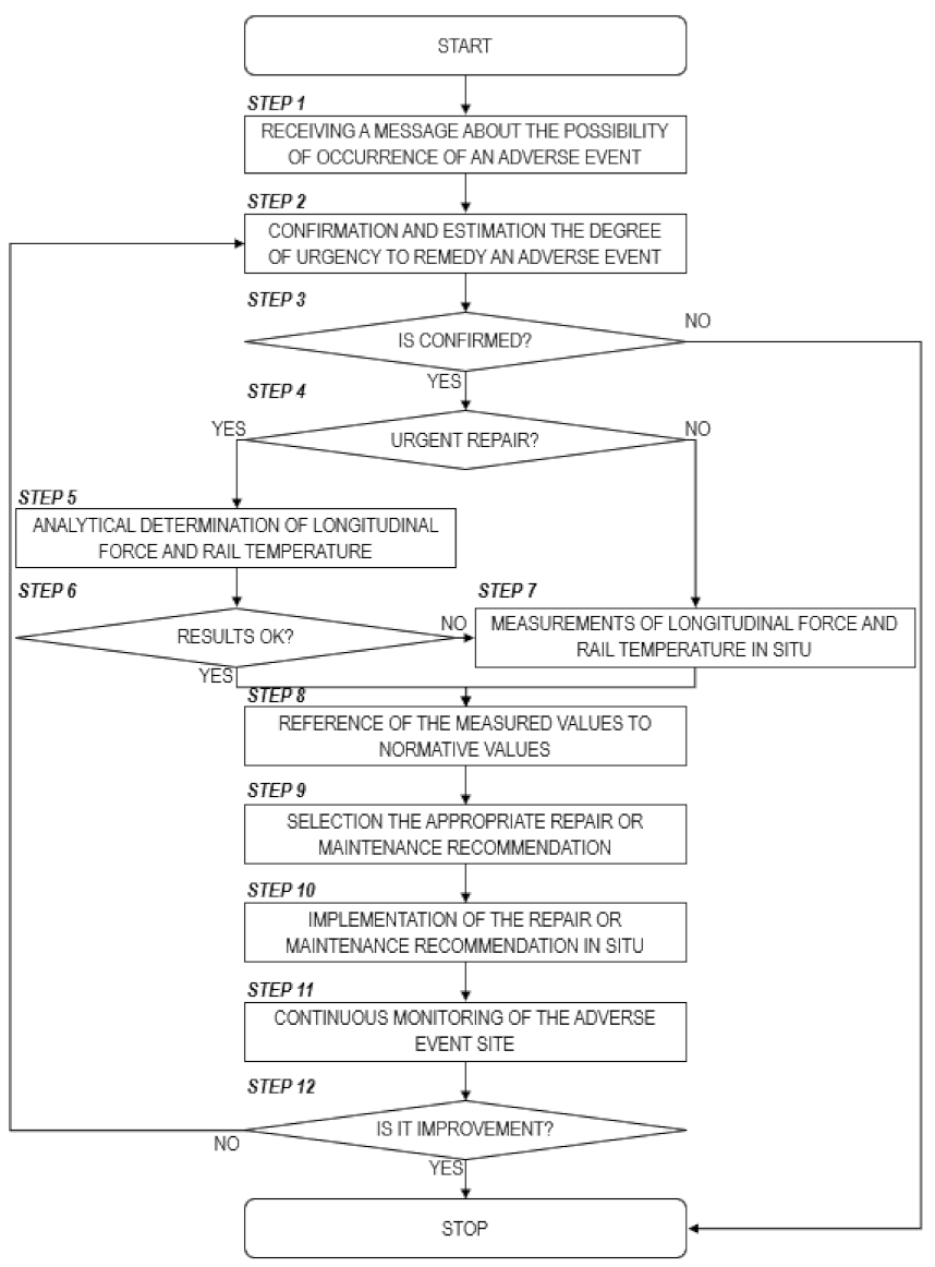
- Step 1: the infrastructure manager’s unit responsible for continuous welded track maintenance receives a message from a duty manager/dispatcher, based on information from the driver, about the possibility of occurrence of an adverse event that may have a direct impact on railway traffic safety; then proceed to step 2,
- Step 2: the infrastructure manager’s unit responsible for continuous welded track maintenance confirms the occurrence of the adverse event (usually by visual inspection of the site) and estimates the degree of urgency to remedy it (taking into account the traffic load on the site, the probability of primary and secondary delays, etc.); then proceed to step 3,
- Step 3: Confirmation of the adverse event takes place; if the event has been confirmed then proceed to step 4, otherwise the method ends,
- Step 4: The urgency of the repair is determined; if the urgency is high then proceed to step 5, otherwise proceed to step 7,
- Step 5: if the repair is urgent, there is no time to make measurements on the ground to determine which type of repair or maintenance recommendation to implement; it is therefore proposed to use analytical relationships to determine the value of the longitudinal force and the temperature of the rail based on the analytical formulas proposed by the authors—see Section 6 of the article—and to make a choice on that basis; however, it is first necessary to proceed to step 6,
- Step 6: a verification is made to see if the values of longitudinal force and rail temperature obtained from the analytical calculations are correct according to the maintenance unit, if so, proceed to step 8, otherwise proceed to step 7,
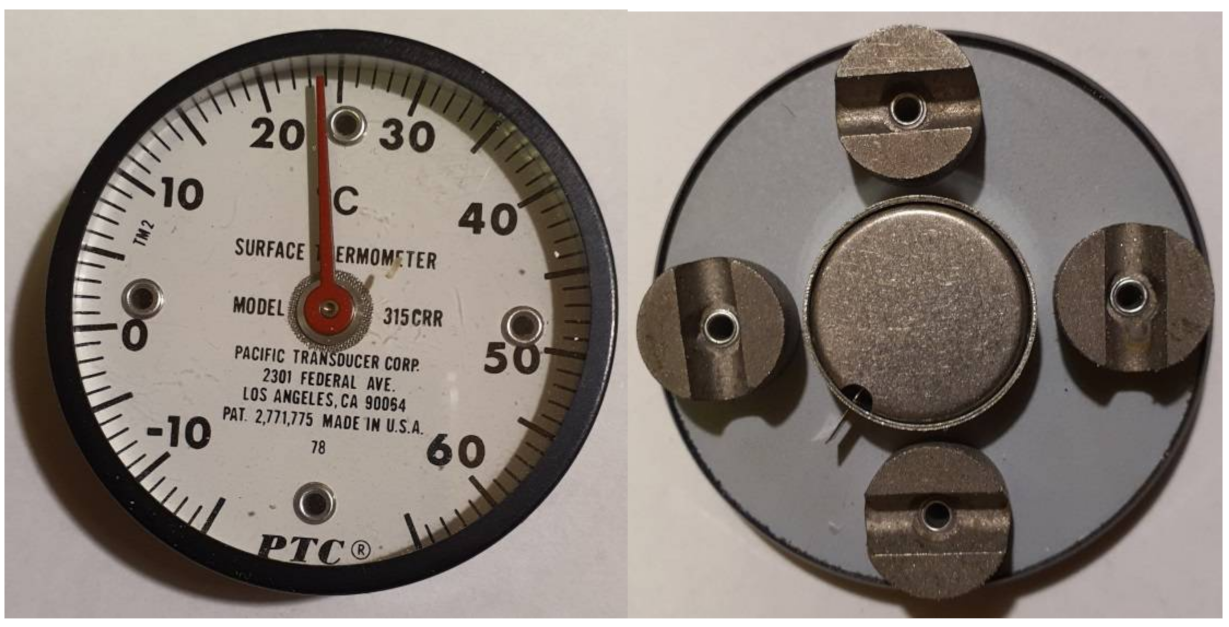
- Step 7: if there is relatively much time to correct the failure or the results of the analytical calculations performed in Step 5 are not satisfactory, the longitudinal force and temperature of the rail on the ground should be measured using an extensometer and a thermometer; then proceed to step 8,
- Step 8: The longitudinal force and rail temperature values obtained by calculation or measurement should be placed into the analytical formulas in Section 3.3 of this article, which contain normative values that allow reference to the set values that allow qualification for implementation of a specific repair or maintenance measure; then proceed to step 9,
- Step 9: Based on the formulas in Section 3.3, select the appropriate repair or maintenance recommendation for the values measured; then proceed to step 10,
- Step 10: The identified repair or maintenance recommendation should be implemented on the ground; the next step is step 11,
- Step 11: After implementing a repair or maintenance recommendation, conduct continuous monitoring of the adverse event site; then proceed to step 12,
- Step 12: the infrastructure manager’s unit responsible for continuous welded track maintenance establishes whether the implemented recommendation has had a positive impact; if so, the procedure ends, otherwise proceed to step 2.
3.2. Parameter Record
| N | – | , where: 1—immediate repair, 2—speed limit, 3—planned repair, 4—standard track supervision, 5—additional track supervision including dangerous places, |
| n | – | recommendation number, n ∊ N, |
| i | – | event number (current or potential), i ∊ I, |
| lk | – | railway line number, lk ∊ LK, |
| km | – | position of the event on railway line lk (km ∊ <0,llk>, llk—length of the line lk, |
| t | – | railway line track number lk, t ∊ T, |
| ts | – | rail number, |
| lok | – | the location vector of the event occurrence, lok = [i,lk,km,t,ts], |
| totocz | – | value of the ambient temperature at the site of the event lok (°C), |
| αsz | – | value of the coefficient of thermal expansion of the rail steel at the event location lok (1/°C), |
| r | – | value of the curve radius at the event location lok (m), |
| oi | – | parameter specifying whether the event has occurred at the engineering structure, if yes: oi = 1, otherwise oi = 0, |
| naw | – | parameter which specifies whether the event has occurred on a conventional surface, if yes: naw = 1, otherwise naw = 0, |
| podk | – | parameter specifying whether the event took place on concrete sleepers, if yes: podk = 1, otherwise (on wooden sleepers) podk = 0. |
3.3. Record of Measured and Normative Parameters
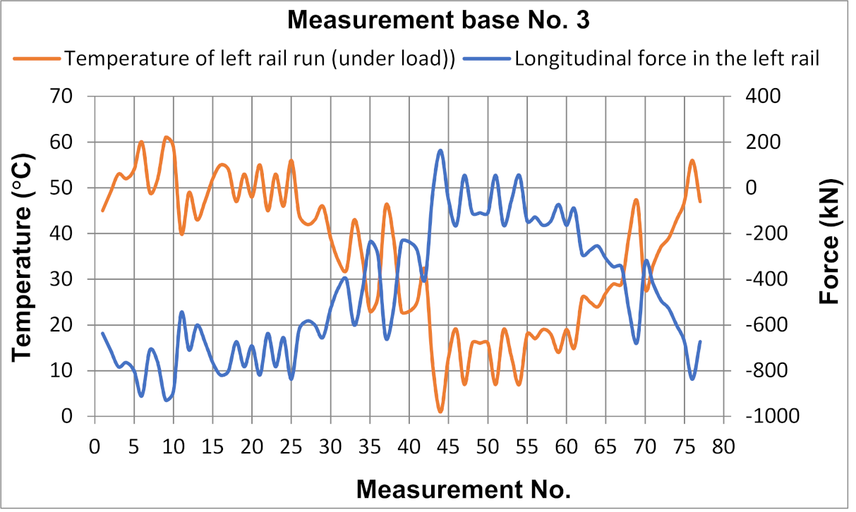
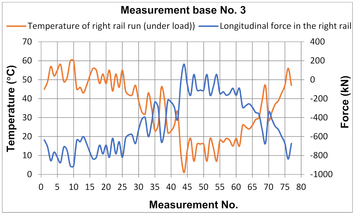
| Fpo | – | the value of the longitudinal force in the rail under load at the location of the event lok (when measurements are taken, the following must also be recorded totocz, αsz, r, oi, naw, podk) (kN), |
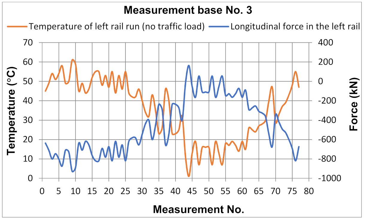
| Fpbo | – | value of the longitudinal force in the unloaded rail at the location of the event lok (when measurements are taken, the following must additionally be recorded totocz, αsz, r, oi, naw, podk) (kN), |
| Tpo | – | value of the temperature of the rail under load at the location of the event lok (when measurements are taken, the following must additionally be recorded totocz, αsz, r, oi, naw, podk) (°C), |
| Tpbo | – | value of the unloaded rail temperature at the location of the event lok (when measurements are taken, the following must additionally be recorded totocz, αsz, r, oi, naw, podk) (°C). |
| Fp,no,min | – | minimum value of the longitudinal force in the rail under load, allowing the effects of the event to be qualified for recommendation number n (kN), |
| Fp,no,max | – | the maximum value of the longitudinal force in the rail under load, allowing the effects of the event to be qualified for recommendation number n (kN), |
| Fp,nbo,min | – | minimum value of the longitudinal force in the unloaded rail, allowing the effects of the event to be qualified for recommendation number n (kN), |
| Fp,nbo,max | – | the maximum value of the longitudinal force in the unloaded rail, allowing the effects of the event to be qualified for recommendation number n (kN), |
| Tp,no,min | – | minimum value of the temperature in the rail under load, allowing the effects of the event to be qualified for recommendation number n (°C), |
| Tp,no,max | – | maximum value of the temperature in the rail under load, allowing the effects of the event to be qualified for recommendation number n (°C), |
| Tp,nbo,min | – | minimum value of the temperature in the unloaded rail, allowing the effects of the event to be qualified for recommendation number n (°C), |
| Tp,nbo,max | – | maximum value of the temperature in the unloaded rail, allowing the effects of the event to be qualified for recommendation number n (°C). |
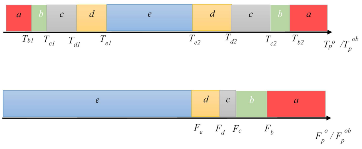
- n(Fpo)—recommendation number resulting from the measured value of the longitudinal force in the rail under load,
- n(Fpbo)—recommendation number resulting from the measured value of the longitudinal force in the unloaded rail,
- n(Tpo)—recommendation number resulting from the measured value of the bus temperature under load,
- n(Tpbo)—recommendation number resulting from the measured value of the temperature of unloaded rail.
4. Research Object
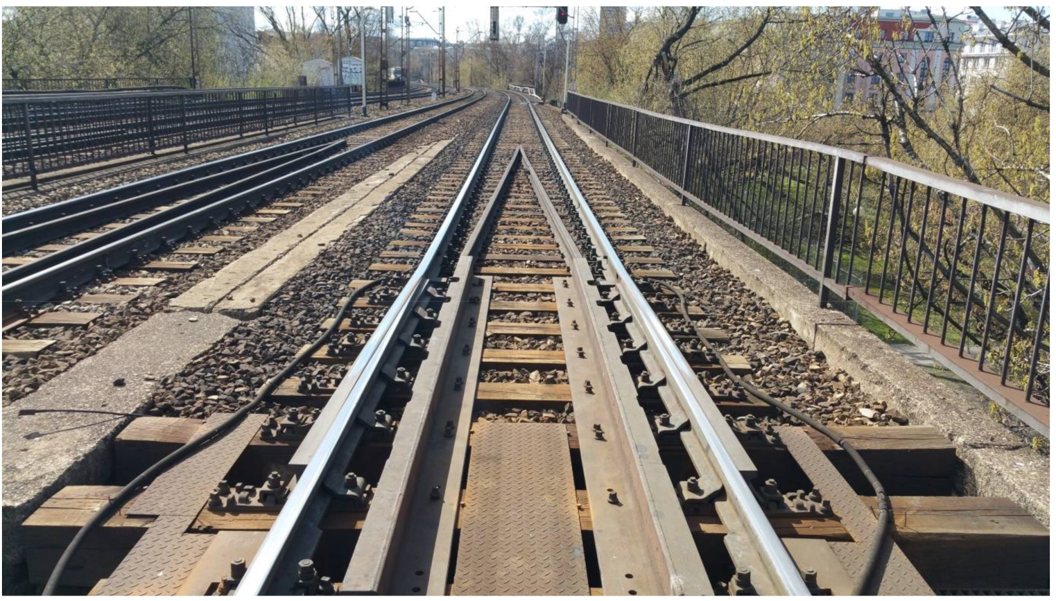
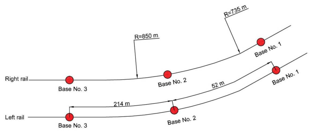
4.1. Description of the Experimental Research Object
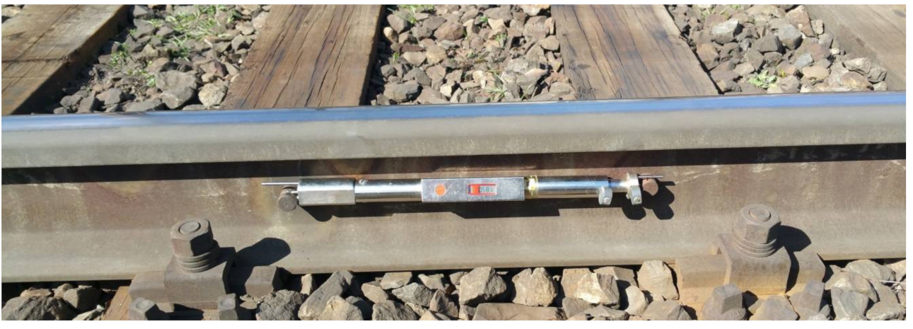
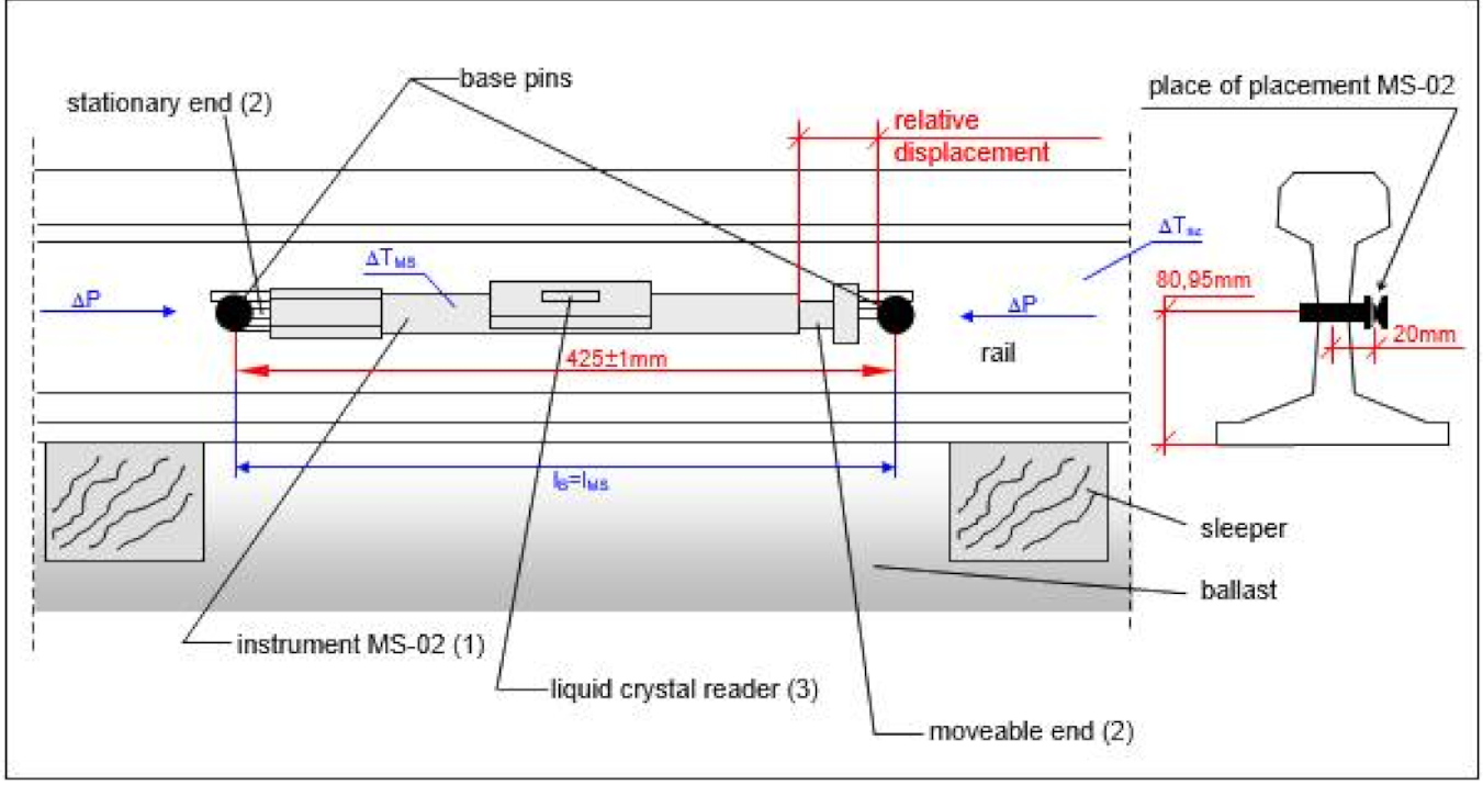
4.2. Description of the Measuring Apparatus
- The casing,
- Two tips (movable and fixed), used to stabilize the position of the instrument relative to the pins during measurement,
- A digital display for direct reading of the instrument indication values expressed in (kN).
5. Experimental Research
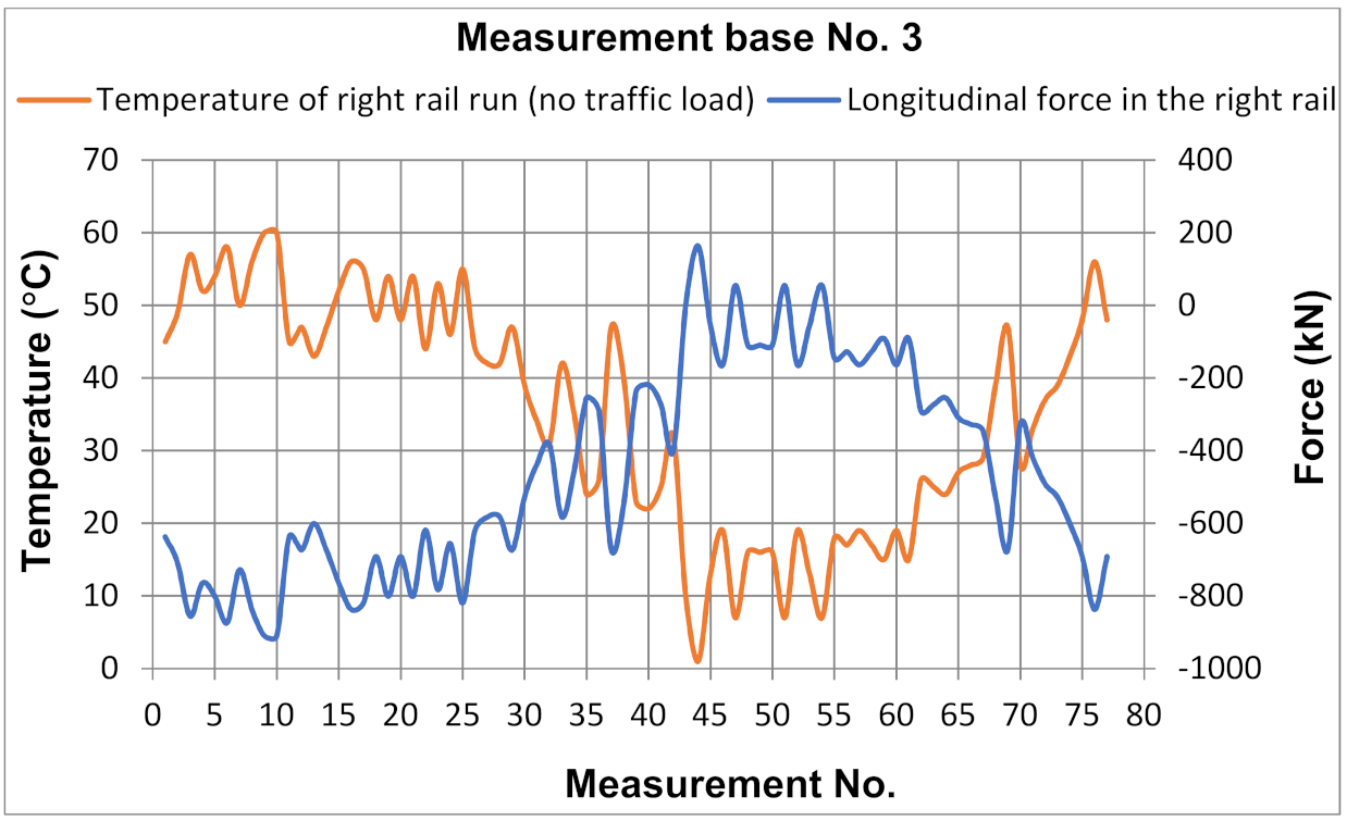
5.1. Assumptions—Test Procedure
- ΔLB—change of the measurement base length on the rail,
- ΔLMS—change in length of the instrument’s measuring base,
- αsz—thermal expansion coefficient of the rail steel,
- αMS—coefficient of thermal expansion of the instrument,
- ΔTsz—change of temperature of the rail,
- ΔTMS—change in the instrument temperature,
- lB—length of the measurement base on the rail,
- lMS—length of the measurement base of the instrument.
- etm—maximum probable error resulting from the difference in thermal properties of the instrument and the rail and the eccentricity of load application equal to 3.08 (K),
- ek—maximum probable error resulting from the existence of horizontal curvature of the track equal to 0.7 (K),
- ep—maximum probable error resulting from the accuracy of applying the instrument to the rail pins equal to 0.55 (K).
5.2. Test Results
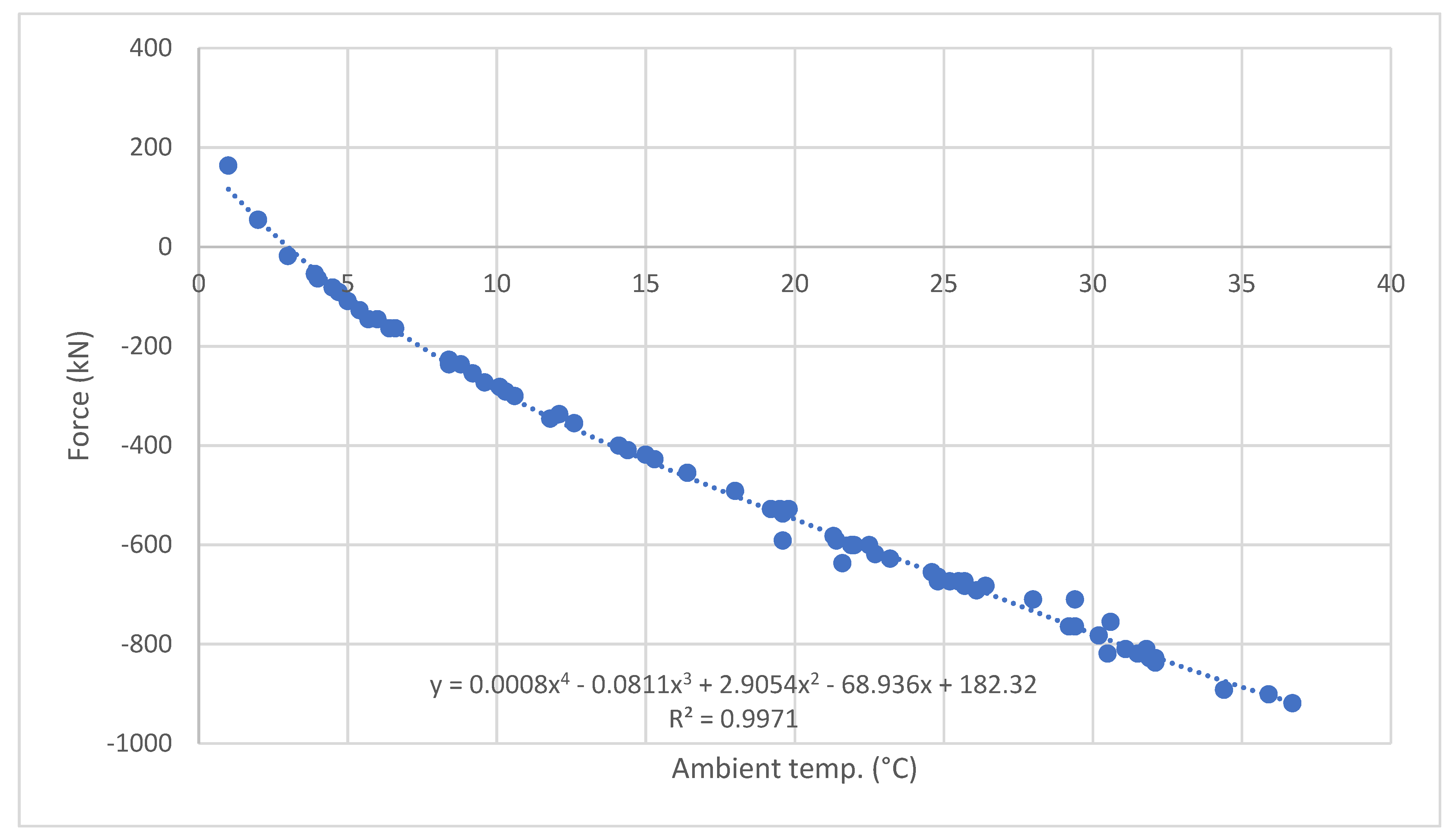
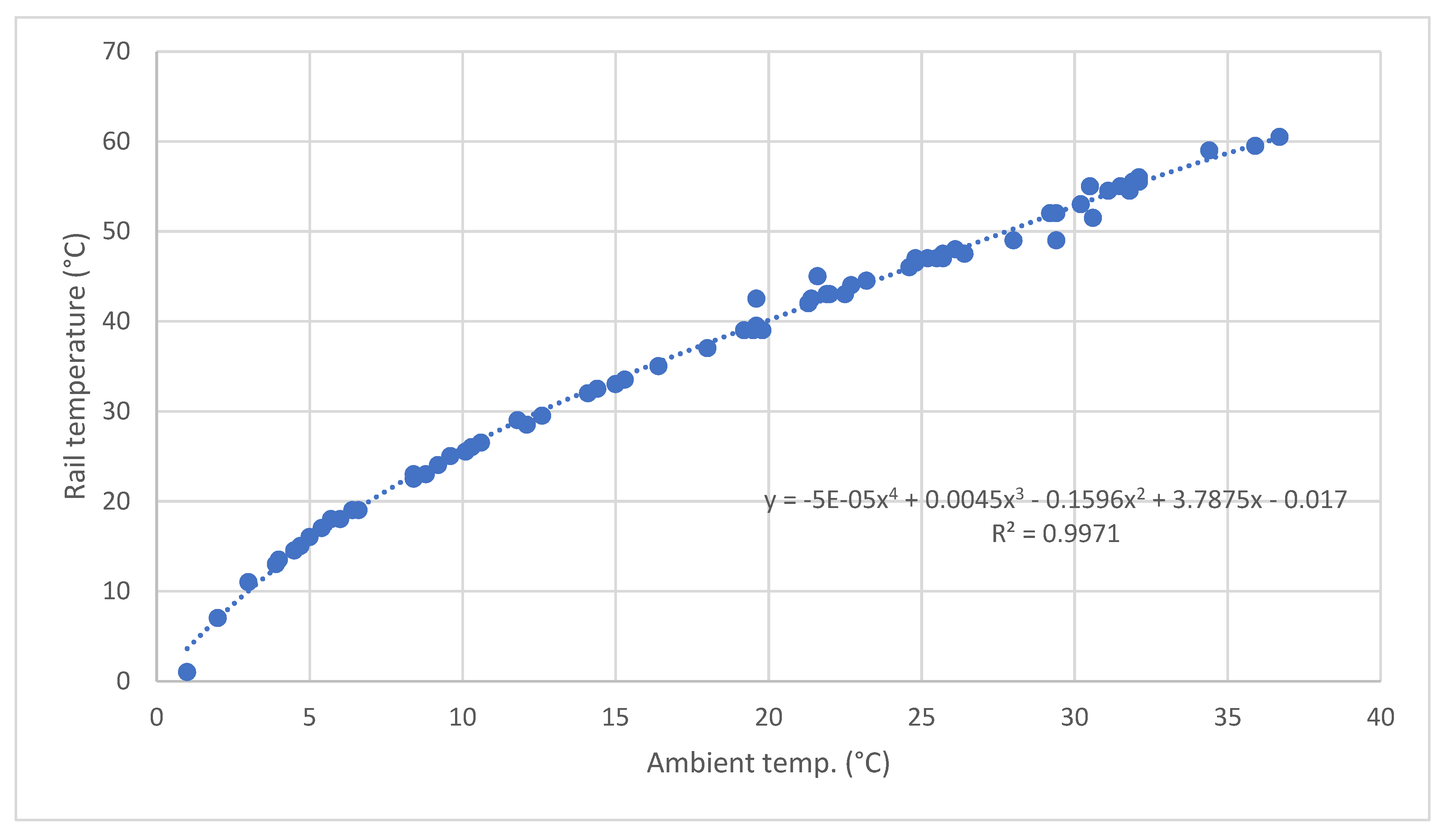
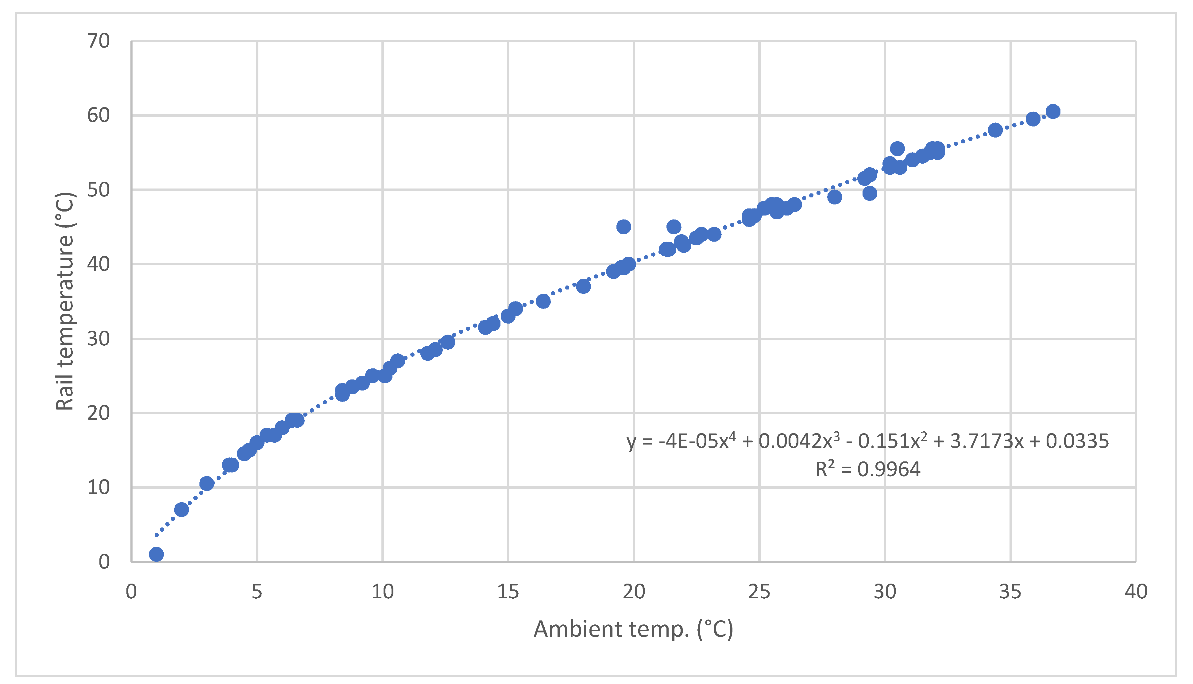
6. Analytical Determination of Rail Temperature and Longitudinal Force Values from a Known Ambient Temperature Value
7. Conclusions
Author Contributions
Funding
Institutional Review Board Statement
Informed Consent Statement
Data Availability Statement
Conflicts of Interest
References
- Gołębiowski, P.; Kukulski, J. Preliminary study of shaping the railway track geometry in terms of their maintenance costs and capacity. Arch. Transp. 2020, 53, 115–128. [Google Scholar] [CrossRef]
- Urbaniak, M.; Kardas-Cinal, E.; Jacyna, M.; Cinal, K. Optimization of Energetic Train Cooperation. Symmetry 2019, 11, 1175. [Google Scholar] [CrossRef] [Green Version]
- Sobota, A.; Żochowska, R.; Szczepański, E.; Gołda, P. The influence of tram tracks on car vehicle speed and noise emission at four-approach intersections located on multilane arteries in cities. J. Vibroeng. 2018, 20, 2453–2468. [Google Scholar] [CrossRef]
- Kasraei, A.; Zakeri, J.A. Effective time interval for railway track geometry inspection. Arch. Transp. 2020, 53, 53–65. [Google Scholar] [CrossRef]
- Kish, A.; Samavedam, G. Risk Analysis Based CWR Track Buckling Safety Evaluations. In Proceedings of the International Conference on Innovations in the Design & Assessment of Railway. 1999. Available online: https://rosap.ntl.bts.gov/view/dot/8514 (accessed on 4 May 2021).
- Burdzik, R.; Nowak, B.; Rozmus, J.; Słowiński, P.; Pankiewicz, J. Safety in the railway industry. Arch. Transp. 2017, 44, 15–24. [Google Scholar] [CrossRef]
- The Heat’s So Strong in Rural Australia, It Bent a Railway Track. Available online: https://www.stuff.co.nz/world/australia/101459018/the-heats-so-strong-in-rural-australia-it-bent-a-railway-track (accessed on 15 April 2021).
- Jacyna, M.; Szczepański, E.; Izdebski, M.; Jasiński, S.; Maciejewski, M. Characteristics of event recorders in Automatic Train Control systems. Arch. Transp. 2018, 46, 61–70. [Google Scholar] [CrossRef]
- Luo, Y. A model for predicting the effect of temperature force of continuous welded rail track. Proc. Inst. Mech. Eng. Part F J. Rail Rapid Transit 1999, 213, 117–124. [Google Scholar] [CrossRef]
- Zakeri, J.A. Lateral resistance of railway track. In Reliability and Safety in Railway; Xavier Perpinya, IntechOpen, 2012; pp. 357–374. Available online: https://www.intechopen.com/books/reliability-and-safety-in-railway/lateral-resistance-of-railway-track (accessed on 4 May 2021).
- Luo, Y.; Li, L.; Yin, H. A dynamic analysis of a continuous welded rail track under a longitudinal stress caused by temperature changes. Proc. Inst. Mech. Eng. Part F J. Rail Rapid Transit 2009, 224, 91–101. [Google Scholar] [CrossRef]
- Kumar, R.; Upadhyay, A. Effect of temperature gradient on track-bridge interaction. Interact. Multiscale Mech. 2012, 5, 1–12. [Google Scholar] [CrossRef]
- Wang, C.Y.; Tsai, H.C.; Chen, C.S.; Wang, H.L. Railway track performance monitoring and safety warning sys-tem. J. Perform. Constr. Facil. 2011, 25, 577–586. [Google Scholar] [CrossRef]
- Kish, A.; Samavedam, G. Track Buckling Prevention: Theory, Safety Concepts, and Applications (No. DOT/FRA/ORD-13/16); John, A., Ed.; Volpe National Transportation Systems Center: Washington, DC, USA, 2013. [Google Scholar]
- Martínez, I.N.; Fernández, P.M.; Sanchis, I.V.; Franco, R.I. Analytical model for predicting the buckling load of continuous welded rail tracks. Proc. Inst. Mech. Eng. Part F J. Rail Rapid Transit 2014, 229, 542–552. [Google Scholar] [CrossRef] [Green Version]
- Rybkin, V.V.; Nastechyk, M.P.; Nastechik, N.P.; Marcul, R.V. Stability issues of the continuous welded rail track on the concrete sleepers on the curves with radius R ≤ 300 m. Sci. Cold Arid Reg. 2013. [Google Scholar] [CrossRef]
- Ciotlaus, M.; Köllő, G. Ballast bed cleaning and recycling—Influence on stability of continuously welded rail track. Procedia Manuf. 2018, 22, 294–300. [Google Scholar] [CrossRef]
- Popović, Z.; Lazarević, L.; Vilotijević, M.; Mirković, N. Interaction phenomenon between train, track and bridge. In Energy Management of Municipal Transportation Facilities and Transport; Springer: Cham, Switzerland, 2017; pp. 3–11. [Google Scholar]
- Li, L.; Luo, Y. CWR track vibration characteristics varying with the change of supporting condition. WIT Trans. Built Environ. 2012, 127, 745–752. [Google Scholar] [CrossRef] [Green Version]
- Chen, R.; Wang, P.; Wei, X.-K. Track-Bridge Longitudinal Interaction of Continuous Welded Rails on Arch Bridge. Math. Probl. Eng. 2013, 2013, 1–8. [Google Scholar] [CrossRef] [Green Version]
- Czyczuła, W.; Sokołowski, J.; Towpik, K. Interaction between CWR track and bridges. Arch. Civ. Eng. 1997, 43, 51–69. [Google Scholar]
- Towpik, K. Variability of stress and longitudinal force distributed in continuous welded rail tracks. Arch. Civ. Eng. 1997, 43, 51–69. [Google Scholar]
- Koc, W.; Wilk, A. Investigations of methods to measure longitudinal forces in continuous welded rail tracks using the tamping machine. Proc. Inst. Mech. Eng. Part F J. Rail Rapid Transit 2009, 223, 61–73. [Google Scholar] [CrossRef]
- Bednarek, W.A. Local subgrade unevenness of lengthwise profile influence on the work conditions of a CWR track. Found. Civil Environ. Eng. 2012, 15, 19–40. [Google Scholar]
- Czyczuła, W.; Massel, A.; Sokołowski, J.; Towpik, K. Empirical investigation of longitudinal creep and breathing of tight curves. In Interim Report PKP/TU-Kraków for ERRI D 202 Committee; European Rail Research Institute: Utrecht, The Nederlands, 1996. [Google Scholar]
- Zhao, W.; Wang, P.; Cao, Y. Simplified algorithms for continuous welded rail design on large-span steel truss cable-stayed bridge. In Proceedings of the 1st International Workshop on High-Speed and Intercity Railways; Springer: Berlin/Heidelberg, Germany, 2012; pp. 173–178. [Google Scholar]
- Adamski, M.; Szelążek, J. Assessment of Stresses in Rails of a CWR Track. Research Report; Laboratory of Ultrasonic Materials Testing, IPPT-PAN: Warsaw, Poland, 1998. (In Polish) [Google Scholar]
- Lo, C.C.H.; Paulsen, J.A.; Kinser, E.R.; Jiles, D.C. Quantitative evaluation of stress distribution in magnetic materials by Barkhausen effect and magnetic hysteresis measurements. IEEE Trans. Magn. 2004, 40, 2173–2175. [Google Scholar] [CrossRef]
- Gomes, R.; Batista, A.; Ortigueira, M.; Rato, R.; Baldeiras, M. Railscan: A Tool for the Detection and Quantification of Rail Corrugation. In Emerging Trends in Technological Innovation. DoCEIS 2010. IFIP Advances in Information and Communication Technology; Camarinha-Matos, L.M., Pereira, P., Ribeiro, L., Eds.; Springer: Berlin/Heidelberg, Germany, 2010; Volume 314. [Google Scholar] [CrossRef] [Green Version]
- Zarembski, A.M.; Palese, J.W. Managing risk on the railway infrastructure. In Proceedings of the 7th World Congress on Railway Research, Montreal, QC, Canada, 4–8 June 2006. [Google Scholar]
- Kukulski, J.; Towpik, K. Ocena naprężeń własnych w procesie produkcji szyn i stalowych elementów rozjazdów. In Scientific Papers of the Warsaw University of Technology; Transport; WUT Journal of Transportation Engineering: Warsaw, Poland, 2006; pp. 87–104. [Google Scholar]
- Nucera, C.; Lanza di Scalea, F. Nondestructive measurement of neutral temperature in continuous welded rails by nonlinear ultrasonic guided waves. J. Acoust. Soc. Am. 2014, 136, 2561–2574. [Google Scholar] [CrossRef]
- Barker, C.; Hoult, N.A.; Zhang, M. Development of an Axial Strain Measurement System for Rails. J. Perform. Constr. Facil. 2021, 35, 04020145. [Google Scholar] [CrossRef]
- Wang, P.; Xie, K.; Shao, L.; Yan, L.; Xu, J.; Chen, R. Longitudinal force measurement in continuous welded rail with bi-directional FBG strain sensors. Smart Mater. Struct. 2016, 25, 015019. [Google Scholar] [CrossRef]
- Urakawa, F.; Abe, K.; Takahashi, H. Improvement of occuracy of method for measuring axial forces of rail based on natural fre-quency. Q. Rep. RTRI 2016, 27, 125–132. [Google Scholar] [CrossRef] [Green Version]
- Kukulski, J.; Jacyna, M.; Gołębiowski, P. Finite Element Method in Assessing Strength Properties of a Railway Surface and Its Elements. Symmetry 2019, 11, 1014. [Google Scholar] [CrossRef] [Green Version]
- Wattmann, J. Lägskräfte im Eisenbahngleis; Otto Elsner Verlag: Darmstadt, Germany, 1957. [Google Scholar]
- IRS 70712—Rail Defects. 2018. Available online: https://www.normadoc.com/english/uic-70712-2018-05.html (accessed on 4 May 2021).
- UIC Leaflet 720- Laying and Maintenance of CWR Track. 2005. Available online: https://www.shop-etf.com/en/leaflet-720-r-laying-and-maintenance-of-cwr-track (accessed on 4 May 2021).
- Feng, Q.-S.; Zong, D.-M.; Lei, X.-Y. Finite element model for analyzing the stability of continuously welded rail track. Proc. Inst. Mech. Eng. Part F J. Rail Rapid Transit 2004, 218, 225–233. [Google Scholar]
- Ižvolt, L.; Dobeš, P.; Pieš, J. Verification of boundary conditions of numerical modeling of the track substructure thermal regime – influence of the snow cover. Arch. Transp. 2018, 4, 51–60. [Google Scholar] [CrossRef] [Green Version]
- Kish, A.; Samavedam, G. Dynamic Buckling of Continuous Welded Rail Track. In Transportation Research Record; European Rail Research Institute: Boston, MA, USA, 1991. [Google Scholar]
- Kish, A.; Samavedam, G. Recent investigations on track lateral limits for highspeed rail applications. In WCRR Materials; European Rail Research Institute: Florence, Italy, 1997. [Google Scholar]
- Kish, A. CWR—BUCKLE, Version 2.0. Program and User’s Guide; ERRI D202/DT 365; European Rail Research Institute: Utrecht, The Nederlands, 1997. [Google Scholar]
- Pucillo, G.P. Thermal buckling and post-buckling behaviour of continuous welded rail track. Veh. Syst. Dyn. 2016, 54, 1785–1807. [Google Scholar] [CrossRef] [Green Version]
- Miri, A.; Dhanasekar, M.; Thambiratnam, D.; Weston, B.; Chan, T.H.T. Chan Analysis of buckling failure in continuously welded railway tracks. Eng. Fail. Anal. 2021, 119, 104989. [Google Scholar] [CrossRef]
- Yang, G.; Bradford, M.A. Bradford Thermal-induced buckling and postbuckling analysis of continuous railway tracks. Int. J. Solids Struct. 2016, 97–98, 637–649. [Google Scholar] [CrossRef]
- Sysyn, M.; Gerber, U.; Kovalchuk, V.; Nabochenko, O. The complex phenomenological model for prediction of inhomogeneous deformations of railway ballast layer after tamping works. Arch. Transp. 2018, 47, 91–107. [Google Scholar] [CrossRef] [Green Version]
- Jamka, M. A new method of measuring longitudinal forces in the rails of a WWR track. In Zeszyty Naukowo-Techniczne Oddziału SITkom w Krakowie; zeszyt 21; Zesyty Naukowo: Krakow, Poland, 1992. [Google Scholar]
- Czyczuła, W.; Lajos, I.; Towpik, K.; Massel, A. Long-term investigations of CWR track behaviour. In Report PKP, MAV and TU-Kraków for ERRI D 202 Committee; European Rail Research Institute: Utrecht, The Nederlands, 1997. [Google Scholar]

Publisher’s Note: MDPI stays neutral with regard to jurisdictional claims in published maps and institutional affiliations. |
© 2021 by the authors. Licensee MDPI, Basel, Switzerland. This article is an open access article distributed under the terms and conditions of the Creative Commons Attribution (CC BY) license (https://creativecommons.org/licenses/by/4.0/).
Share and Cite
Kukulski, J.; Gołębiowski, P.; Makowski, J.; Jacyna-Gołda, I.; Żak, J. Effective Method for Diagnosing Continuous Welded Track Condition Based on Experimental Research. Energies 2021, 14, 2889. https://doi.org/10.3390/en14102889
Kukulski J, Gołębiowski P, Makowski J, Jacyna-Gołda I, Żak J. Effective Method for Diagnosing Continuous Welded Track Condition Based on Experimental Research. Energies. 2021; 14(10):2889. https://doi.org/10.3390/en14102889
Chicago/Turabian StyleKukulski, Jacek, Piotr Gołębiowski, Jacek Makowski, Ilona Jacyna-Gołda, and Jolanta Żak. 2021. "Effective Method for Diagnosing Continuous Welded Track Condition Based on Experimental Research" Energies 14, no. 10: 2889. https://doi.org/10.3390/en14102889
APA StyleKukulski, J., Gołębiowski, P., Makowski, J., Jacyna-Gołda, I., & Żak, J. (2021). Effective Method for Diagnosing Continuous Welded Track Condition Based on Experimental Research. Energies, 14(10), 2889. https://doi.org/10.3390/en14102889


