Abstract
Static eccentricity (SE) is frequently generated by manufacturing processes. As the nonuniformity of the air-gap length is caused by the SE, the torque ripple and cogging torque increase in the motor. This study analyzes the distorted back electromotive force (EMF) and cogging torque due to SE. Further, a motor design considering SE is performed for stable back EMF and low cogging torque. First, the SE was diagnosed and analyzed using the back EMF and cogging torque measured from the test results of the base model. In addition, the rotor position was calculated using the unbalanced back EMF due to the SE. The calculated rotor position is used when analyzing phenomena due to SE and applied to robust design. Subsequently, robust design optimization was performed to improve the unbalanced back EMF and cogging torque due to SE. Using finite element analysis (FEA) considering SE, the shape of the stator was designed based on the base model. The estimated rotor position from the base model was applied to the optimum model to confirm its robustness from SE’s effects. Finally, the base and optimum models were compared through the test results.
1. Introduction
Permanent magnet synchronous motors (PMSMs) are widely used in industrial and automotive applications. PMSMs are classified as surface-mounted permanent magnet synchronous motor (SPMSM) and interior permanent magnet synchronous motor (IPMSM) according to the location of the PM. In particular, SPMSM is used in various applications owing to its low cogging torque and torque ripple [,]. However, cogging torque and torque ripple of motors increase due to rotor eccentricity. Rotor eccentricity is frequently generated for various reasons, such as the assembly tolerances of bearings or housings, defects in bearings, and the manufacturing process of the motor [,,,,,]. Rotor eccentricity is classified into static eccentricity (SE) and dynamic eccentricity (DE). SE and DE are caused by the eccentricity displacement between the central axis of the stator and rotor []. Therefore, cogging torque and torque ripple increase because the air-gap length due to SE and DE becomes nonuniform [,,].
Rotor eccentricity can be diagnosed and analyzed using simulation and test results of cogging torque, vibration, phase current, and impedance. The periodicity of the cogging torque is the least common multiple (LCM) of the number of poles and slots in a healthy motor. However, the additional harmonic order of cogging torque is generated by the rotor eccentricity. SE or DE is diagnosed using the additional harmonic order [,,,,,,]. Vibration caused by rotor eccentricity is analyzed by measuring the amplitude and frequency of the vibration and calculating the deformation of the motor. As a vibration phenomenon caused by rotor eccentricity, an additional vibration order is created, or the amplitude of vibration increases compared to a healthy motor [,,]. Further, an imbalance between the phase current and impedance occurs due to the rotor eccentricity. By measuring the phase current, impedance, and sensor, the type of rotor eccentricity can be distinguished by using the deviation of the amplitude [,,,,,]. Next, a control technique is used to solve the unstable motor performance caused by rotor eccentricity with various diagnostic methods [,,,]. Owing to the current imbalance caused by rotor eccentricity, current harmonics are injected using the inverter and control []. However, this operation involves complex algorithms and high-quality electronic components. Therefore, it is necessary to study the methods that can effectively minimize the influence of rotor eccentricity.
The contribution of this study is to diagnose the type of rotor eccentricity and predict the rotor position by analyzing the back electromotive force (EMF) and cogging torque. Further, a robust design process considering rotor eccentricity was proposed for stable back EMF and low cogging torque. The rotor position is necessary to accurately analyze rotor eccentricity. However, it is very difficult to estimate the rotor position by measuring eccentric displacement and angle. Unlike other papers, this manuscript not only diagnoses rotor eccentricity but also estimates eccentric displacement and angle. The rotor eccentricity type is diagnosed from the test results of the back EMF. In addition, the eccentric displacement and angle were estimated using the FEA simulation and the variance of the test results for the back EMF. The calculated rotor position was applied in the robust design to improve the unstable back EMF and cogging torque. The torque ripple or cogging torque increases as the air gap length is nonuniform due to the rotor eccentricity. Therefore, a motor design considering the rotor eccentricity is necessary to reduce the cogging torque and torque ripple. To solve the problem caused by rotor eccentricity, this manuscript proposes a robust design process. The stability of the designed optimum model over the base model from rotor eccentricity is verified using finite element analysis (FEA), including the measured rotor position.
This paper is organized as follows: In Section 2, the rotor eccentricity is defined analytically. In Section 3, the type of rotor eccentricity is distinguished through harmonic analysis by measuring the back EMF and cogging torque in the base model. Then, the rotor position is identified based on the analyzed back EMF. In Section 4, a robust design is developed based on rotor eccentricity. The optimum model is determined using robust design optimization. The estimated rotor position is applied as an analysis condition to confirm the robustness of the optimum model to rotor eccentricity. In Section 5, the base and optimum models are compared through the test results of the back EMF and cogging torque. It is verified that the optimum model is more robust to rotor eccentricity than the base model.
2. Static and Dynamic Eccentricity
Rotor eccentricity is generated by various reasons, such as mass production, bearing defects, and assembly tolerances. It can be typically classified into SE and DE, as shown in Figure 1. The SE and DE are expressed as:
where e is the eccentricity displacement, Os is the stator axis, Or is the rotor axis, Oω is the rotation axis, k is the relative eccentricity, and go is the air-gap length in a healthy condition. A healthy motor rotates with Os, Or, and Oω positioned at the origin. Therefore, the air-gap length is uniform. In the case of SE, Os is located at the origin. However, Or and Oω is located at eccentricity displacement. In the case of DE, Os and Oω are located at the origin. However, Or is located at eccentricity displacement. The SE and DE are such that the air-gap length is nonuniform. The air-gap length is expressed as:
where α is the mechanical angle of the rotor, p is pole pair, θ is the eccentricity angle, and ω is the angular velocity of the electrical angle. The air-gap length is time-independent in the case of the SE since Or and Oω are located in the same position. When the SE is generated, the air-gap length is t = 0 in (3). The air-gap length is time-dependent in the case of the DE since Or and Oω are not located in the same position. Therefore, when DE is generated, the air-gap length is considered according to the time.
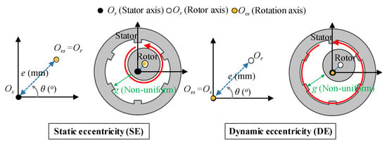
Figure 1.
Definition for static and dynamic eccentricity.
The main factor determining motor performance is air-gap flux density, which is related to the amplitude and waveform of the back EMF and the cogging torque. The air–gap flux density is defined as:
where Bg is the air-gap flux density, Fpm is the magnetomotive force (MMF) caused by the PM, and Λ is the relative permeance of the air gap. The MMF caused by the PM is expressed as:
where μ is the spatial harmonic order of the air-gap MMF caused by the PM. The relative permeance is defined as:
where μ0 is the vacuum permeability, and kc is Carter’s coefficient. Consequently, the nonuniformity of the air-gap length caused by the rotor eccentricity affects the relative permeance. Therefore, the amplitude and frequency of the air-gap flux density are determined based on the occurrence of SE or DE.
3. Diagnosis and Analysis of Base Model
Figure 2 summarizes the process for diagnosing the rotor eccentricity of the base model. Figure 3 shows the structure and winding arrangement of the base model. The specifications of the base model are listed in Table 1. The type of rotor eccentricity can be diagnosed from the back EMF waveform of the test result and the 8-pole 9-slot winding arrangement. In addition, the rotor position can be identified by analyzing the amplitude of the back EMF. The identified rotor position is reflected in the base model, and FEA simulation is performed to confirm the cogging torque waveform. Moreover, it compares and analyses cogging torque waveforms from test and simulation results.
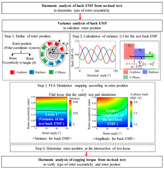
Figure 2.
Diagnosis process for determining the type of rotor eccentricity and rotor position.
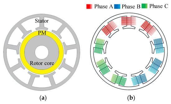
Figure 3.
Base model (a) structure (b) winding arrangement.

Table 1.
Specifications of the base model.
3.1. Back EMF Analysis to Diagnose Rotor Eccentricity
The flux linkage is related to the air-gap flux density, which is influenced by the air-gap length of (3). When the air-gap length becomes nonuniform due to SE or DE, the flux linkage is generated to be unbalanced. In particular, as the coils of A, B and C phases are concentrated in one region of the winding arrangement, the difference in the flux linkage of A, B, and C phases becomes large due to SE or DE. To confirm the difference in the back EMF waveform due to SE and DE, the FEA simulation was performed based on the specification of the base model in Table 1.
As a simulation condition, the relative eccentricity was half of the air-gap length. Figure 4 shows the simulation results of the back EMF considering the SE. By using the back EMF waveform and the harmonic analysis result, it can be confirmed that a deviation in the back EMF amplitude of each phase is generated during the mechanical cycle. As the rotor rotates at a specific position, the back EMF of the A phase, which is closest to the rotor position, has the largest amplitude. Figure 5 shows the simulation results of the back EMF considering the DE. By using the back EMF waveform and the harmonic analysis result, it can be confirmed that the maximum values of the back EMF in the A, B, and C phases are the same during the mechanical cycle. Therefore, the difference between SE and DE can be confirmed from the back EMF waveform and harmonic analysis of the simulation result.
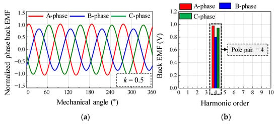
Figure 4.
Simulation result of back EMF considering static eccentricity (a) waveform (b) harmonic analysis.
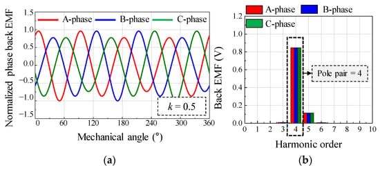
Figure 5.
Simulation result of back EMF considering dynamic eccentricity (a) waveform (b) harmonic analysis.
To diagnose the type of rotor eccentricity for the base model, a no-load test was performed. Figure 6 shows the test equipment for measuring the back EMF and cogging torque. When electrical energy is supplied to the AC servo motor from the power supply, the test motor rotates to generate back EMF and cogging torque. The back EMF was measured through a voltage probe. The cogging torque was measured through a torque sensor. The oscilloscope was used to record and store data of back EMF and cogging torque waveform. The reducer was used to lower the speed range. Figure 7 shows the test results of the back EMF at 1000 rpm. The test results of the back EMF harmonic analysis are summarized in Table 2. There was a deviation in the measured phase back EMF owing to the rotor eccentricity. The amplitude of the A-phase back EMF was the largest, and the C-phase back EMF was the smallest. Further, since the deviation of the phase back EMF was maintained when the motor was rotating, it could be diagnosed as SE.

Figure 6.
Test equipment for measuring back EMF and cogging torque.
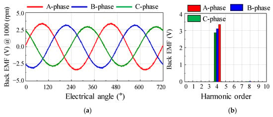
Figure 7.
No-load test result of back EMF for the base model (a) waveform (b) harmonic analysis.

Table 2.
No-load test result of back EMF harmonic analysis.
The rotor position was calculated to analyze the phenomenon of SE. The rotor position could be divided into eccentricity displacement and angle. Figure 8 shows the simulation condition of the eccentricity displacement and angle using the polar coordinate system. The range of eccentricity displacement was determined from 0 mm to 0.25 mm. In Figure 4, simulation was performed considering the eccentricity displacement of 0.25 mm (k = 0.5) in the base model. The deviation of the back EMF obtained from the result of the FEA simulation was about 20%. In Figure 7, the deviation of the back EMF obtained from the test result was about 10%. Therefore, in Figure 8, the eccentric displacement of the base model was included within 0 mm to 0.25 mm. The range of eccentricity angle was determined considering the winding arrangement of 8-pole and 9-slot. The test results are shown in Table 2. In Figure 8, the windings of the A phase are located within 0° to 120°. In addition, 0° to 60° and 0° to 120° were symmetric. The amplitude of the back EMF of the test result was the smallest in the C phase back EMF. If the eccentricity angle ranged between 60° and 120°, the A-phase back EMF was the largest, and the B phase back EMF was the smallest. Therefore, to predict the eccentricity angle from the test result, it was determined that the range of the eccentricity angle for analyzing the FEA simulation was 0° to 60°. Figure 9 shows the simulation results of the back EMF variance and the amplitude of the A-phase back EMF according to the eccentricity displacement and angle. The variance was expressed as:
where u is the average value, n is the number of variables, and xi is the variable. The variance is the mean of the squared deviations. The variables are the amplitude of the back EMF in the A, B, and C phases. The relationship between the back EMF and SE could be confirmed indirectly from the simulation results. Therefore, the eccentricity displacement and angle could be determined at the point that satisfies both the test and the simulation resulted using the back EMF variance and the amplitude of the A-phase back EMF. Using the FEA simulation of the base model, the back EMF in the A, B, and C phased was analyzed according to the eccentricity displacement and angle. Subsequently, the back EMF variance was calculated from the back EMF test results to estimate the eccentricity displacement and angle.
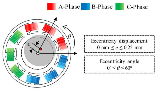
Figure 8.
Condition of eccentricity displacement and angle.
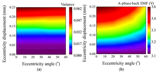
Figure 9.
Simulation result of according to eccentricity displacement and angle (a) back EMF variance (b) back EMF amplitude.
Figure 10 shows the process of determining the eccentricity displacement and angle. First, the variance in the base model of the 8-pole 9-slot was calculated using (7) from the test result of the back EMF in Table 2. The A phase back EMF with the largest amplitude was selected because the B phase and C phase back EMF were considered in the FEA simulation according to the eccentricity displacement and angle. Next, the locus was expressed to match the test and simulation results with each other. The locus of variance was satisfied with a comparison of the test and simulation results for the back EMF variance. The locus of amplitude was satisfied with a comparison of the test and simulation resulted for the amplitude of the A phase back EMF. The intersection point of the loci of variance and amplitude was considered as the eccentricity displacement and angle. Therefore, the SE could be diagnosed, and the eccentricity displacement and angle could be calculated.
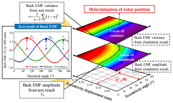
Figure 10.
Determination of eccentricity displacement and angle.
3.2. Cogging Torque Analysis to Diagnose Rotor Eccentricity
The cogging torque was determined by the magnetic stored energy generated from the air-gap flux density. Ignoring the slot effect and considering that the permeability of the iron core is infinite, the magnetic stored energy generated in the air gap of the SPMSM can be calculated as:
where Br is the remanence of the PM, and hm is the thickness of the PM. The cogging torque is determined by the air-gap length and flux density. The air-gap length and flux density become nonuniform due to SE. Therefore, the periodicity of the cogging torque is generally the LCM of the number of poles and the number of slots, but additional harmonic order is also generated by SE.
Figure 11 shows the test and simulation results of the cogging torque for the base model. The test setup is shown in Figure 6. Two types of simulation resulted were considered: one was performed under healthy conditions using FEA simulation, and the other was performed by applying the estimated eccentricity displacement and angle using FEA simulation. The periodicity of the cogging torque in a healthy motor was the LCM of the number of poles and slots. Furthermore, the amplitude of the cogging torque was considerably small. However, when the simulation was performed by applying the predicted eccentricity displacement and angle, the 8th harmonic order was the largest in the simulation results. In the base model of the 8-pole 9-slot motor, it could be confirmed that the harmonic order for the number of poles was caused by SE. In addition, the SE could be analyzed through the harmonic orders of the cogging torque from the test resulted. In particular, the 8th harmonic order was most remarkable. The amplitude and harmonic order of the cogging torque were similar in the test and simulation results. Therefore, the SE was confirmed using the simulation and test result of the cogging torque.
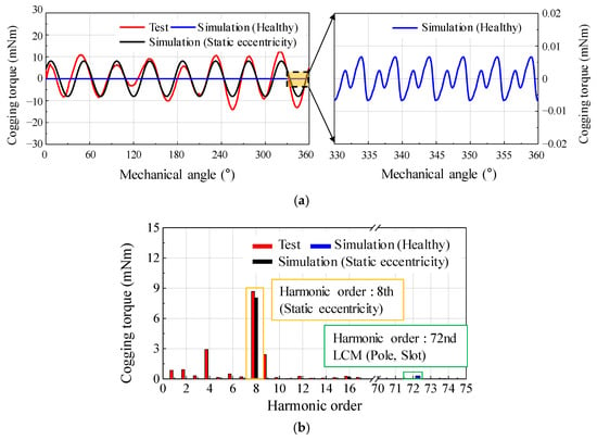
Figure 11.
Comparison of simulation (healthy, static eccentricity) and test result of cogging torque (a) waveform (b) harmonic analysis.
4. Robust Design Optimization Considering Static Eccentricity
As mentioned in Section 3, the unbalanced back EMF and cogging torque due to SE are confirmed in the base model of the 8-pole 9-slot motor. SE is an unavoidable phenomenon caused by various manufacturing processes or conditions. The design goal of this study is to improve the stable back EMF and low cogging torque while including the SE. The design process for reducing the unbalanced back EMF and cogging torque is summarized in Figure 12. The number of slots in the stator is changed from 9 to 12 to remove the unbalanced back EMF. Robust design optimization is employed to reduce the cogging torque. First, the design of the experiment (DOE) is established using a combination of optimal Latin hypercube design (OLHD) and sequential maximin distance design (SMDD) to create a kriging surrogate model.
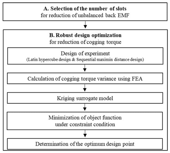
Figure 12.
Design processes for minimizing the effect of static eccentricity.
Subsequently, the FEA simulation was used to analyze the cogging torque based on DOE and calculate the cogging torque variance. By using the generated kriging surrogate model, the design point was determined for the minimization of the objective function under the constraint condition. Finally, the eccentricity displacement and angle predicted in Section 3 were applied to the optimum model. Subsequently, it was confirmed that the back EMF and cogging torque were improved when the optimum model compared with the base model even if SE was generated.
4.1. Selection for the Number of Slots
The unbalanced back EMF due to the SE can be effectively removed by changing the number of slots. Figure 13 shows a comparison of the winding arrangements of the 8-pole 9-slot and the 8-pole 12-slot motor. To confirm the back EMF considering SE according to the change in the number of slots, the design conditions were based on the base model of stator outer diameter, outer rotor diameter, number of poles, and power specifications. As discussed in Section 3, if the SE were generated in an 8-pole 9-slot motor, the back EMF became unstable. In the 8-pole 9-slot motor, the windings of the A, B, and C phases were, respectively, placed in a single region of the stator. Therefore, the deviation of the back EMF in the A, B, and C phases was generated by the interaction of the nonuniform in the air–gap length and the 8-pole 9-slot winding arrangement. However, in the 8-pole 12-slot motor, the windings of the A, B, and C phases were evenly placed in the stator. The amplitude of the back EMF in the A, B, and C phases was generated by constant even if the nonuniform in the air-gap length occurred. The maximum number of slots that could be manufactured was 12 slots, considering the thickness of the teeth. Therefore, the number of slots was decided as 12 slots, considering the robustness of the back EMF due to SE and manufacturing conditions.
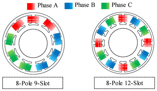
Figure 13.
Comparison of winding arrangement between the 8-pole 9-slot and 8-pole 12-slot motor.
4.2. Robust Design Optimization
4.2.1. Definition of the Design and Cogging Torque Variables
For accurate design, robust design optimization was conducted based on the base model specified in Table 1. Stator outer diameter, outer rotor diameter, pore length, core material, and magnet material are the same. Figure 14 shows a summary of the design variables. They are the tooth tip, slot opening, and tooth thickness. Further, the slot area was maintained constant to determine the yoke thickness according to the tooth thickness. To confirm the variation of cogging torque due to SE, the design parameters with uncertainties were determined as eccentricity displacement and angle as described in Section 3. Table 3 summarizes the maximum and minimum values of the design variables and the design parameters with uncertainties. Statistically, the cogging torque variance could be calculated to evaluate the cogging torque due to the SE. The cogging torque variance was based on Taylor’s expansion in the approximate variance []. As design parameters with uncertainties, the eccentricity displacement and angle were assumed to be from Gaussian distributions. The cogging torque variance was defined as:
where σf is the standard deviation of cogging torque variance, σp is the standard deviation of the Gaussian distribution for the design parameter, μp is the mean of the Gaussian distribution for the design parameter, and h is the derivative of the design parameter. By calculating the cogging torque variance according to design variables, the relationship between the effect of SE and the design variables could be confirmed. Finally, the design variables were determined by selecting for minimizing the cogging torque variance.
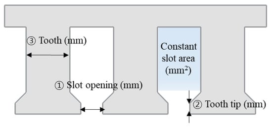
Figure 14.
Design variable.

Table 3.
Boundaries of design variable and design parameter with uncertainties.
4.2.2. Kriging Surrogate Model and Determination of the Optimum Design Point
The kriging surrogate model, such as a response surface model and an artificial neural network, is mainly applied to the optimal design of an electric motor []. The kriging surrogate model is used to anticipate the cogging torque variance within the range of design variables and parameters with uncertainties. Further, the kriging surrogate model is generated by applying OLHD and SMDD as DOE []. Figure 15 shows sample points according to design variables using OHLD and SMDD as DOE. The number of sample points was determined as 270 through the DOE. Sample points within the range of the design variable were properly distributed by applying OLHD and SMDD. Figure 16 represents the established part of the kriging surrogate model. From the determined sample points in Figure 15, the cogging torque was calculated using FEA simulation. Kriging was used as a method for interpolating data within a surrogate model.
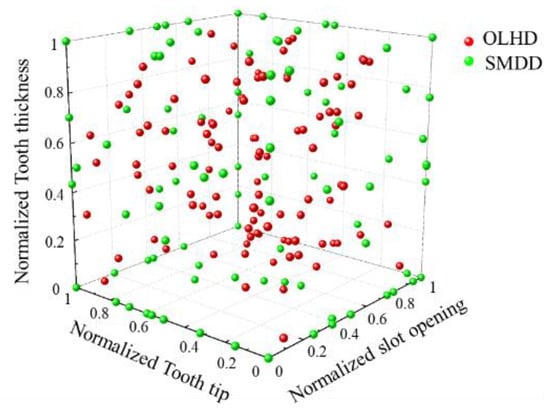
Figure 15.
Design of the experiment using a combination of OLHD and SMDD.
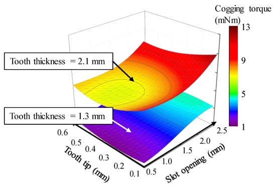
Figure 16.
Kriging surrogate model.
The kriging surrogate model was needed for verification using the leave-one-out cross-validation method []. The normalized root-mean-square error (NRMSE) was defined as:
where ns is the number of sample points, and x is the vector of parameters with uncertainties and design variables. Y(x) is the vector of the response values, which can be the cogging torque. Y(xi) is the response at the ith point estimated from the FEA simulation. is the anticipated response at the ith point estimated from the kriging surrogate model []. The NRMSEs for the cogging torque variance were calculated to be 1.3%. The objective function and constraint condition were used to determine the optimum design point from the kriging surrogate model. They were defined as:
where V is the vector of the design variables, P is the vector of the design parameters with uncertainties, F is the objective function for minimizing the cogging torque variance, G is the constraint condition, and Vdc is the DC link voltage. The constraint condition was considered to not exceed the DC link voltage, as shown in Table 1. The optimum design point was determined considering the objective function and constraint condition.
As part of the kriging surrogate model, Figure 17 shows the results of the cogging torque variance according to the slot opening and tooth tip with a tooth thickness of 1.3 mm. The optimum design point was selected as the point with the smallest cogging torque variance while satisfying the DC voltage limit.
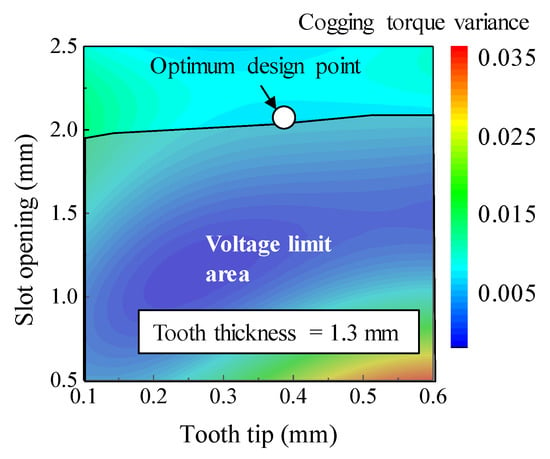
Figure 17.
Cogging torque variance according to the design variables.
4.2.3. Optimum Model
Figure 18 shows the optimum model of the 8-pole 12-slot motor using robust design optimization. When comparing the base and the optimum model, the stator shape is different. Further, the optimum model is simulated by applying the eccentricity displacement, and angle predicted from the base model in Section 3. The robustness of the back EMF and cogging torque due to SE is analyzed by comparing it with the results obtained from the optimum model.
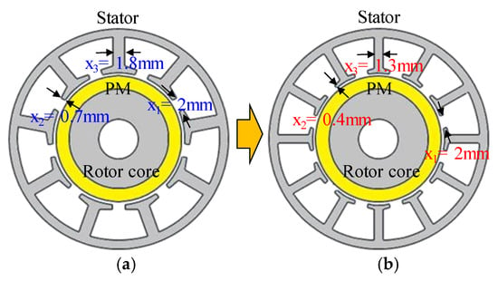
Figure 18.
Motor shape (a) base model (b) optimum model.
Figure 19 shows the simulation results of the back EMF for the optimum model. Figure 20 shows the simulation results of the cogging torque for the optimum model. Even if SE occurs in the optimum model, a balanced back EMF is generated. The cogging torque could be confirmed that the 8th harmonic order occurred owing to the SE and the 24th harmonic order harmonic occurred according to the LCM for the numbers of poles and slots. Notably, the cogging torque amplitude did not increase significantly. Consequently, a balanced back EMF and low cogging torque were generated in the optimum model.
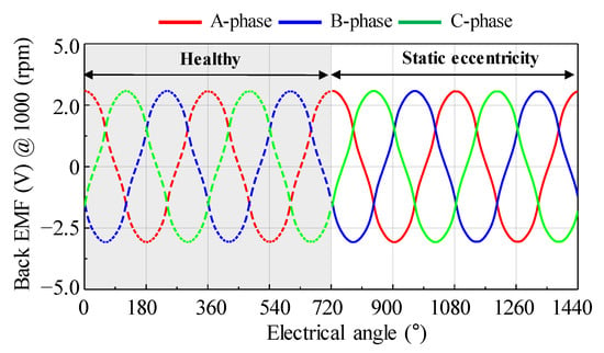
Figure 19.
Simulation result of back EMF for the optimum model considering healthy and static eccentricity condition.
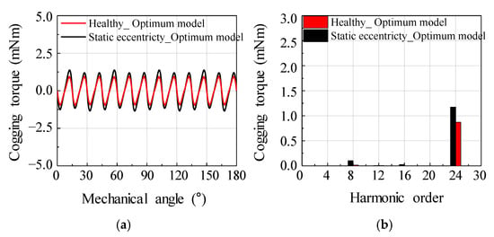
Figure 20.
Simulation result of cogging torque for the optimum model considering health and static eccentricity condition (a) waveform (b) harmonic analysis.
5. Design Result and Verification
A motor with stator, rotor and assembly was used to verify the performance of the optimum model, as shown in Figure 21. The number of stator teeth was 12. The stator shape was determined by the dimensional information obtained from the optimum design resulted. The rotor, bearing, and housing were manufactured with the same specifications as the base model, like manufacturing quality. Therefore, the base and the optimum models differed only in the stator shape but had the same motor size.
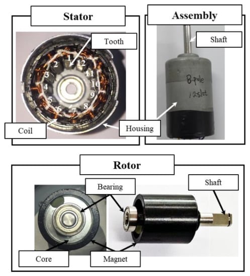
Figure 21.
Stator, rotor and assembly for the optimum model.
Figure 22 shows the results of the back EMF waveform for the base and optimum models. Figure 23 shows the results of the cogging torque waveform for the base and optimum models. Figure 24 shows the simulation result of torque ripple for the base and the optimum model by applying the eccentricity displacement and angle. The optimum model had better back EMF and cogging torque performance than the base model, reducing torque ripple.
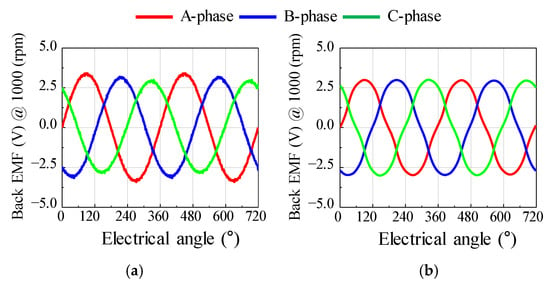
Figure 22.
The test result of back EMF (a) base model (b) optimum model.
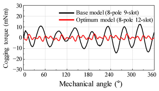
Figure 23.
The test result of cogging torque for the base and optimum model.
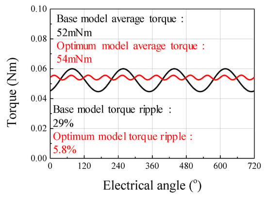
Figure 24.
The simulation result of torque ripple for the base and optimum model.
The base and optimum models were compared based on the test results, as shown in Figure 25. When SE occurred, an unbalanced back EMF was generated in the base model, whereas a balanced back EMF was generated in the optimum model. Comparing the difference between the maximum and minimum amplitudes of the phase back EMF on the test results, the deviation for the base model was 0.27, and that for the optimum model was 0.04. The cogging torque of the optimum model was reduced by approximately 73.7% compared to that of the base model.
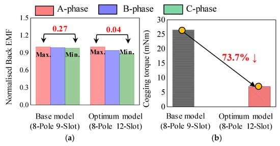
Figure 25.
Comparison of test results (a) back EMF (b) cogging torque.
6. Conclusions
In this study, the SE generated in SPMSM was diagnosed and analyzed. Further, a motor design method using robust design optimization was proposed to improve the unstable back EMF and cogging torque caused by SE. It was possible to classify the type of rotor eccentricity by harmonic analysis of the measured back EMF and cogging torque in the base model of an 8-pole 9-slot motor. The eccentricity displacement and angle were analyzed and estimated using the 8-pole 9-slot winding arrangement and the deviation of the back EMF. Subsequently, the stator shape was designed through robust design optimization. The deviation of the back EMF was reduced by changing the number of slots in the stator from 9 to 12. Then, the stator shape with the lowest cogging torque variance was designed. It was confirmed that the optimum model was more robust to the effect of SE than the base model. Finally, the back EMF and cogging torque test results of the base and optimum models were compared and verified. As future work, except for the 8-pole and 9-slot confirmed in this study, there was a need to investigate other combinations of the number of poles and slots to estimate the eccentricity displacement and angle. It was also necessary to study whether it was possible to diagnose DE or magnet fault other than SE.
Author Contributions
Methodology, J.-C.P.; investigation, J.-C.P., S.-H.P. and J.-H.K.; validation, J.-C.P. and S.-G.L.; visualization, S.-H.P.; supervision, G.-H.L. and M.-S.L.; writing—review and editing, J.-C.P., S.-H.P., J.-H.K., S.-G.L., G.-H.L. and M.-S.L. All authors have read and agreed to the published version of the manuscript.
Funding
This work was supported by the National Research Foundation of Korea funded by the Korea government (Ministry of Science, ICT & Future Planning) under Grant 2018R1C1B5085447.
Institutional Review Board Statement
Not applicable.
Informed Consent Statement
Not applicable.
Conflicts of Interest
The authors declare no conflict of interest.
References
- Lee, C.-S.; Cha, K.-S.; Park, J.-C.; Lim, M.-S. Tolerance-Insensitive Design of the Magnet Shape for a Surface Permanent Magnet Synchronous Motor. Energies 2020, 13, 1311. [Google Scholar] [CrossRef]
- Song, B.-K.; Kim, D.-K.; Kim, S.-I.; Park, H.-J.; Lee, G.-H.; Lim, M.-S. Comparative Study on Surface-Mounted Permanent Magnet Motors With Segmented and Connected Core for Brake System. IEEE Access 2020, 8, 167930–167938. [Google Scholar] [CrossRef]
- Park, S.-H.; Park, J.-C.; Hwang, S.-W.; Kim, J.-H.; Park, H.-J.; Lim, M.-S. Suppression of Torque Ripple Caused by Misalignment of the Gearbox by Using Harmonic Current Injection Method. IEEE/ASME Trans. Mechatron. 2020, 25, 1990–1999. [Google Scholar] [CrossRef]
- Tong, W.; Li, S.; Pan, X.; Wu, S.; Tang, R. Analytical Model for Cogging Torque Calculation in Surface-Mounted Permanent Magnet Motors with Rotor Eccentricity and Magnet Defects. IEEE Trans. Energy Convers. 2020, 35, 2191–2200. [Google Scholar] [CrossRef]
- Lee, H.-K.; Shin, K.-H.; Bang, T.-K.; Nah, J.-H.; Choi, J.-Y. Experimental Verification and Analytical Study of Influence of Rotor Eccentricity on Electromagnetic Characteristics of Permanent Magnet Machine. IEEE Trans. Appl. Supercond. 2020, 30, 1–5. [Google Scholar] [CrossRef]
- Rajagopalan, S.; Le Roux, W.; Habetler, T.G.; Harley, R.G. Dynamic Eccentricity and Demagnetized Rotor Magnet Detection in Trapezoidal Flux (Brushless DC) Motors Operating Under Different Load Conditions. IEEE Trans. Power Electron. 2007, 22, 2061–2069. [Google Scholar] [CrossRef]
- Goktas, T.; Zafarani, M.; Akin, B. Discernment of Broken Magnet and Static Eccentricity Faults in Permanent Magnet Synchronous Motors. IEEE Trans. Energy Convers. 2016, 31, 578–587. [Google Scholar] [CrossRef]
- Ajily, E.; Ardebili, M.; Abbaszadeh, K. Magnet Defect and Rotor Eccentricity Modeling in Axial-Flux Permanent-Magnet Machines via 3-D Field Reconstruction Method. IEEE Trans. Energy Convers. 2015, 31, 486–495. [Google Scholar] [CrossRef]
- Faiz, J.; Ebrahimi, B.; Akin, B.; Toliyat, H. Comprehensive Eccentricity Fault Diagnosis in Induction Motors Using Finite Element Method. IEEE Trans. Magn. 2009, 45, 1764–1767. [Google Scholar] [CrossRef]
- Ogidi, O.O.; Barendse, P.S.; Khan, M.A. Influence of Rotor Topologies and Cogging Torque Minimization Techniques in the Detection of Static Eccentricities in Axial-Flux Permanent-Magnet Machine. IEEE Trans. Ind. Appl. 2016, 53, 161–170. [Google Scholar] [CrossRef]
- Barmpatza, A.C.; Kappatou, J.C. Study of a Combined Demagnetization and Eccentricity Fault in an AFPM Synchronous Generator. Energies 2020, 13, 5609. [Google Scholar] [CrossRef]
- Ebrahimi, B.M.; Faiz, J.; Roshtkhari, M.J. Static-, Dynamic-, and Mixed-Eccentricity Fault Diagnoses in Permanent-Magnet Synchronous Motors. IEEE Trans. Ind. Electron. 2009, 56, 4727–4739. [Google Scholar] [CrossRef]
- Del Pizzo, A.; Di Noia, L.P.; Fedele, E. A Simple Analytical Model of Static Eccentricity for PM Brushless Motors and Validation through FEM Analysis. Energies 2020, 13, 3420. [Google Scholar] [CrossRef]
- Faiz, J.; Nejadi-Koti, H. Eccentricity fault diagnosis indices for permanent magnet machines: State-of-the-art. IET Electr. Power Appl. 2019, 13, 1241–1254. [Google Scholar] [CrossRef]
- Madariaga, C.; Jara, W.; Riquelme, D.; Bramerdorfer, G.; Tapia, J.A.; Riedemann, J. Impact of Tolerances on the Cogging Torque of Tooth-Coil-Winding PMSMs with Modular Stator Core by Means of Efficient Superposition Technique. Electronics 2020, 9, 1594. [Google Scholar] [CrossRef]
- Kim, J.; Yoon, M.; Hong, J.; Kim, S. Analysis of cogging torque caused by manufacturing tolerances of surface-mounted permanent magnet synchronous motor for electric power steering. IET Electr. Power Appl. 2016, 10, 691–696. [Google Scholar] [CrossRef]
- Gasparin, L.; Cernigoj, A.; Markic, S.; Fiser, R. Additional Cogging Torque Components in Permanent-Magnet Motors Due to Manufacturing Imperfections. IEEE Trans. Magn. 2009, 45, 1210–1213. [Google Scholar] [CrossRef]
- Coenen, I.; Van Der Giet, M.; Hameyer, K. Manufacturing Tolerances: Estimation and Prediction of Cogging Torque Influenced by Magnetization Faults. IEEE Trans. Magn. 2011, 48, 1932–1936. [Google Scholar] [CrossRef]
- Ou, J.; Liu, Y.; Qu, R.; Doppelbauer, M. Experimental and Theoretical Research on Cogging Torque of PM Synchronous Motors Considering Manufacturing Tolerances. IEEE Trans. Ind. Electron. 2018, 65, 3772–3783. [Google Scholar] [CrossRef]
- Islam, R.; Husain, I. Analytical Model for Predicting Noise and Vibration in Permanent-Magnet Synchronous Motors. IEEE Trans. Ind. Appl. 2010, 46, 2346–2354. [Google Scholar] [CrossRef]
- Salah, A.A.; Dorrell, D.G.; Guo, Y. A Review of the Monitoring and Damping Unbalanced Magnetic Pull in Induction Machines Due to Rotor Eccentricity. IEEE Trans. Ind. Appl. 2019, 55, 2569–2580. [Google Scholar] [CrossRef]
- Veras, F.C.; Lima, T.L.V.; Souza, J.S.; Ramos, J.G.G.S.; Filho, A.C.L.; Brito, A.V. Eccentricity Failure Detection of Brushless DC Motors from Sound Signals Based on Density of Maxima. IEEE Access 2019, 7, 150318–150326. [Google Scholar] [CrossRef]
- Vaseghi, B.; Nahid-Mobarakh, B.; Takorabet, N.; Meibody-Tabar, F. Inductance Identification and Study of PM Motor with Winding Turn Short Circuit Fault. IEEE Trans. Magn. 2011, 47, 978–981. [Google Scholar] [CrossRef]
- Wu, Y.; Ma, G. Anti-Interference and Location Performance for Turn-to-Turn Short Circuit Detection in Turbo-Generator Rotor Windings. Energies 2019, 12, 1378. [Google Scholar] [CrossRef]
- Aggarwal, A.; Strangas, E.G. Review of Detection Methods of Static Eccentricity for Interior Permanent Magnet Synchronous Machine. Energies 2019, 12, 4105. [Google Scholar] [CrossRef]
- Lasjerdi, H.; Nasiri-Gheidari, Z.; Tootoonchian, F. Online Static/Dynamic Eccentricity Fault Diagnosis in Inverter-Driven Electrical Machines Using Resolver Signals. IEEE Trans. Energy Convers. 2020, 35, 1973–1980. [Google Scholar] [CrossRef]
- Park, J.-K.; Hur, J. Detection of Inter-Turn and Dynamic Eccentricity Faults Using Stator Current Frequency Pattern in IPM-Type BLDC Motors. IEEE Trans. Ind. Electron. 2015, 63, 1771–1780. [Google Scholar] [CrossRef]
- Ebrahimi, B.M.; Faiz, J. Feature Extraction for Short-Circuit Fault Detection in Permanent-Magnet Synchronous Motors Using Stator-Current Monitoring. IEEE Trans. Power Electron. 2010, 25, 2673–2682. [Google Scholar] [CrossRef]
- Park, J.-K.; Jeong, C.-L.; Lee, S.-T.; Hur, J. Early Detection Technique for Stator Winding Inter-Turn Fault in BLDC Motor Using Input Impedance. IEEE Trans. Ind. Appl. 2014, 51, 240–247. [Google Scholar] [CrossRef]
- Wang, B.; Wang, J.; Griffo, A.; Sen, B. Experimental Assessments of a Triple Redundant Nine-Phase Fault-Tolerant PMA SynRM Drive. IEEE Trans. Ind. Electron. 2019, 66, 772–783. [Google Scholar] [CrossRef]
- Shakouhi, M.; Mohamadian, M.; Afjei, E. Fault-Tolerant Control of Brushless DC Motors Under Static Rotor Eccentricity. IEEE Trans. Ind. Electron. 2015, 62, 1400–1409. [Google Scholar] [CrossRef]
- Wu, X.; Zhu, Z.Q.; Wu, Z.; Liu, T.; Li, Y. Analysis and Suppression of Rotor Eccentricity Effects on Fundamental Model Based Sensorless Control of Permanent Magnet Synchronous Machine. IEEE Trans. Ind. Appl. 2020, 56, 4896–4905. [Google Scholar] [CrossRef]
- Xia, C.L.; Xiao, Y.W.; Chen, W.; Shi, T.N. Torque ripple Reduction in Brushless DC drives Based on Reference Current Opti-mization Using Integral Variable Structure Control. IEEE Trans. Ind. Electron. 2014, 61, 738–752. [Google Scholar] [CrossRef]
- Park, G.-J.; Lee, T.-H.; Lee, K.H.; Hwang, K.-H. Robust Design: An Overview. AIAA J. 2006, 44, 181–191. [Google Scholar] [CrossRef]
- Kim, S.; Lee, S.-G.; Kim, J.-M.; Lee, T.H.; Lim, M.-S. Robust Design Optimization of Surface-Mounted Permanent Magnet Synchronous Motor Using Uncertainty Characterization by Bootstrap Method. IEEE Trans. Energy Convers. 2020, 35, 2056–2065. [Google Scholar] [CrossRef]
- Kim, S.; Lee, S.-G.; Kim, J.-M.; Lee, T.H.; Hong, J.-P. Uncertainty identification method using kriging surrogate model for industrial electromagnetic device. In Proceedings of the Tenth International Conference on Computational Electromagnetics (CEM 2019), Edinburgh, UK, 19–20 June 2019; Volume 14. [Google Scholar] [CrossRef]
- Queipo, N.V.; Haftka, R.T.; Shyy, W.; Goel, T.; Vaidyanathan, R.; Tucker, P.K. Surrogate-based analysis and optimization. Prog. Aerosp. Sci. 2005, 41, 1–28. [Google Scholar] [CrossRef]
- Lee, S.-G.; Kim, S.; Park, J.-C.; Park, M.-R.; Lee, T.H.; Lim, M.-S. Robust Design Optimization of SPMSM for Robotic Actuator Considering Assembly Imperfection of Segmented Stator Core. IEEE Trans. Energy Convers. 2020, 35, 2076–2085. [Google Scholar] [CrossRef]
Publisher’s Note: MDPI stays neutral with regard to jurisdictional claims in published maps and institutional affiliations. |
© 2021 by the authors. Licensee MDPI, Basel, Switzerland. This article is an open access article distributed under the terms and conditions of the Creative Commons Attribution (CC BY) license (https://creativecommons.org/licenses/by/4.0/).