1. Introduction
The main source of electrical power is a synchronous generator. The electric power system is complex, and a stable power system operates in equilibrium. In large-interconnected power systems, the variation in load and generation initiates rotors of synchronous machines to swing, causing changes in machine rotor angles, terminal voltages, and frequencies that affect the power system equilibrium. Furthermore, the efficiency of alternators, long transmission lines, distribution lines, and all appliances connected to the power system are affected by these changing characteristics. After a perturbation, synchronous machines attempt to regain equilibrium but at different rotor angles. Therefore, oscillations that are not damped completely may lead to an increase in low frequency oscillations in power networks, causing problems in system stability and reducing the power transfer capacity of transmission lines [
1,
2,
3]. The power system’s low frequency oscillations are classified into two types, one with local area modes of oscillation that have a frequency range from 0.8 to 3 Hz and the other with inter-area modes of oscillations that range from 0.2 to 0.7 Hz [
4].
The power system stability can be mainly divided into three types, namely, voltage, angle, and frequency. Voltage stability is the power system’s ability to maintain the required acceptable voltages at all nodes after perturbation, such as a change in active and reactive load demands under normal operating conditions. The change in node voltages due to active and reactive power demands are associated with the rotor angles, and is a local phenomenon, but it has widespread effects on a significant portion of the power system and can lead to voltage collapse. Angle stability is the ability of a power system’s synchronous machines to remain in a synchronized state or regain synchronism after being subjected to a physical disturbance. Any variations in load cause changes in rotor speed of the synchronous generator that further affect the generated output and rotor angle at different synchronous rotor speeds. Under equilibrium conditions, the rotor speed has synchronous speed and machines have a balance between electromagnetic and mechanical torques. Changes in rotor speed, rotor angle, and generated output cause synchronous machines to have oscillations in power networks due to an imbalance in the mechanical and electromagnetic torques [
1]. Frequency stability is the ability of a power system to maintain the required, acceptable frequency against large variations in load or generation. These variations include large loads suddenly being connected to or disconnected from a power system and large generating units being disconnected by a protection system, creating a power imbalance between what is delivered by the turbines and what is consumed by the load [
2].
In effectively dampening the electromechanical oscillations, the formulation of the objective function plays a key role by using a combination of indicators of the power system. In angle stability analysis, creating an objective function that efficiently locates the eigenvalues in a more stable region in the complex s-plane is important. The indicators that assess the angle stability are the damping ratio and a factor of the eigenvalues, determined from imaginary and real eigenvalues of complex power systems. The angle stability can be assessed using a damping factor that improves results by shifting eigenvalues towards the left of the imaginary axis of the complex s-plane using formulations of the maximized real parts of each eigenvalue as an objective function of minimization. The damping ratio shifts the eigenvalues towards the real axis of the complex s-plane using formulations of the minimum damping ratio of each eigenvalue as an objective function of maximization [
5].
Proper implementation of damping devices is required to dampen oscillations and thus maintain or improve the power system’s stability. Different schemes and modelling approaches have been used for damping, such as power system stabilizers (PSSs), flexible alternating current transmission systems (FACTS), and coordination control. The PSS controller, with the excitation system of synchronous machine controls, outputs power by providing the additional synchronizing torque in phase with speed deviations to dampen the required oscillations and improve the power angle stability [
1,
4].
The stability of a system is a primary concern because synchronous machines should remain in a synchronous state while working with other machines in a group or with generators of other regions to form large-interconnected power systems. Perturbation in the system produces low frequency oscillations and affects electrical generation that could lead to unstable machines that trip other units and collapse the system. Application of a PSS is a first measure to enhance the small signal stability. A PSS is the preferred method to improve the power system damping effect [
6,
7]; its installation is economical and effective for stabilizing low frequency oscillations within a system [
6,
8,
9].
Different types of FACTS devices—series, shunt, series shunt, and series-series—have been used to dampen oscillations in power systems through proper design of controllers by injecting or absorbing reactive power. Two FACTS shunt devices, static VAR compensators (SVC) and static synchronous compensators (STATCOM), have been used for damping to enhance small signal stability [
10]. A damping performance analysis [
11], dynamic control strategy to improve the power flow capabilities [
12], and enhancement of the low voltage ride through capability in power systems [
13] have also been described in the literature. In coordination control, PSS and FACTS devices with efficient coordination among controllers have been combined to dampen both types of oscillations in power systems, namely, local and inter-mode. The coordination control design for the thyristor-controlled series capacitor (TCSC), SVC, and PSS [
14,
15] and of the PSS and series capacitive reactance compensator (SCRC) were used to enhance damping [
16]. Furthermore, STATCOM has been coordinated with PSS-STATCOM and a unified power flow controller (UPFC), and UPFC has been coordinated with a PSS [
17,
18,
19,
20].
Optimization techniques have been widely used to calculate the suitable parameters of PSS and FACTS-based controllers. The controller parameters are tuned by optimization techniques, such as conventional, deterministic, heuristic, and hybrid. The heuristic technique solves the optimization problems using stochastic methods, and its improved techniques are known as metaheuristic algorithms. Various metaheuristic optimization techniques have been used to tune parameters of controllers of PSS and FACTS devices [
4]. The genetic algorithm (GA) was used to design a robust PSS and a coordinated PSS with UPFC [
21,
22,
23]. The particle swarm optimization (PSO) algorithm was used to design a damping controller [
5,
24,
25], as were cuckoo and BAT optimization algorithms [
26,
27]. The firefly optimization algorithm was used to design an SVC damping controller [
28,
29]. Various heuristic algorithms for optimization have used stochastic methods that have deficiencies in solution convergence. GA and PSO have deficiencies in convergence, that is, a local minimum stagnation problem. Several proposed methods provide good exploration in a search space but are limited in exploitation, or vice versa. The main advantage of the sine cosine algorithm (SCA) is in allowing both exploration and exploitation in a search space, that is, for the first and second halves of the iterations, respectively.
This research aimed to develop a model of a machine connected to large system and formulate the objective function based on a maximum damping factor to improve the angle stability of the power system. The PSS was chosen as the proposed device to improve the damping capability of the power system. For an efficient control capability of the PSS, the lead lag controller parameters were optimized. For comparison purposes, the performance of the PSS lead lag controller was tuned with the SCA and the resulting parameters were compared with those optimized with moth flame optimization (MFO) and evolutionary programming (EP) to accurately and effectively predict and assess the angle stability before a power system collapse.
This study presents the application of metaheuristic optimization algorithms and the objective function and then proposes a design for a robust controller of the excitation of a machine-connected infinite bus system. The objective function was formulated as a maximum value of the real part as an indicator, and the SCA was developed to tune the lead lag controller parameters. , , and are time constants for phase compensation and washout of the PSS under different loading conditions to improve damping efficiency in angle stability for a single machine infinite bus (SMIB) system. For comparison of optimization techniques, the PSS controller optimized with the SCA method was compared with the PSS parameters tuned with the MFO and EP algorithms.
In this paper, the small signal stability of a power system was improved by mathematical modelling of a SMIB and formulation of an objective function based on a maximum damping factor. The key highlights of the paper are as follows:
Novel machine parameters utilizing flux in the amortisseur windings are considered in the proposed model of the SMIB system.
The proposed SMIB model linearizes the state space model matrix and a 9 × 9 dimension is obtained that is applied in the eigenvalue analysis.
The SCA optimization technique shows improvement in exploration and exploitation processes and finds maxima or minima in the eigenvalue analysis.
The proposed SCA is validated with the MFO and EP techniques.
The rest of this paper is organized as follows: In
Section 2, a mathematical modelling of the SMIB system and the PSS damping controller parameters for improving damping capabilities of the controller are described. The formulation of the objection function for eigenvalue analysis is illustrated in
Section 3. An overview of the optimization techniques is given in
Section 4. The results under three loading conditions are presented in
Section 5. Conclusions are presented in
Section 6.
2. Mathematical Model of SMIB System with PSS
Figure 1 shows a simple representation of the SMIB power system, which is used for stability purposes, in operation.
Figure 2 shows a synchronous generator
G, with excitation system, amortisseurs, terminal voltage
and a PSS connected to an infinite bus with voltage
through transmission lines of impedance
, with
and
as real and imaginary parts, respectively, that is used to design excitation and PSS damping controllers [
1].
Then, by using a PSS with a basic structure model including AVR, is the exciter system gain constant and is the exciter system constant. , , , and are the gain, time constants for phase compensation, and washout of the PSS, respectively.
Figure 3 shows the block diagram of the SMIB with a PSS, AVR, and exciter.
H is the constant of inertia and
is the damping torque coefficient.
,
, and
are machine constants and
,
,
are the SMIB and excitation systems with PSS and AVR constants.
Referring to
Figure 3, the equations representing the SMIB can be derived as follows:
where
δ is the rotor angle; ω is the rotor speed;
is the field flux;
is the flux due to the d-axis amortisseur;
is the flux due to the q-axis first amortisseur; and
is the flux due to the q-axis second amortisseur. Referring to
Figure 2, the equations representing the excitor with the AVR and PSS are as follows:
The system in
Figure 3 linearized with state space model is given by:
,
and
are machine constants and
,
, and
are the SMIB and excitation system with PSS and AVR constants. The SMIB equations can be expressed in a d-q refence frame of the machine. The currents in the d-axis and q-axis of the machine in terms of state variables
and
δ and their perturbed values can be written as follows:
where
=
(
sin
−
cos
)/D,
=
(
sin
−
cos
)/D,
=
,
=
,
=
+
,
=
+
,
=
+
, and D =
+
.
The perturbed values of electrical torque and field current are obtained from the perturbed values currents
and
.
and
are saturated values of mutual inductances. The change in mechanical torque is zero with constant mechanical input torque.
where
=
(
+
) −
(
+
) and
=
(
+
) −
(
+
) +
.
In the small signal performance analysis, a difference is noted between saturation and incremental saturation for perturbed values of currents and flux linkages. The term saturation is related to total flux linkages and current and incremental saturation is related to the perturbed values of currents and flux linkages. The expressions for
and
are as follows:
The effect of field flux on the system stability with a constant field voltage and a perturbed
is zero, so the field flux changes due to feedback of Δ
δ through
, showing a demagnetizing effect of the armature reaction. The rotor angle variations with changes in air gap torque due to field flux changes are given as follows:
The perturbed linkage field flux, affects the damping torque and synchronizing torque components and depends on the oscillating frequency as follows:
Operating in a steady state and having very low oscillating frequencies. The armature reaction introduces a negative synchronizing torque, and when its value exceeds , the system become monotonically unstable and the steady state stability limit is reached at K1 = .
Operating at much higher oscillating frequencies than . The component of the air gap torque due to is in phase with Δω and leads by from Δδ. introduces a positive damping torque component.
Operating at a 1 Hz oscillating frequency. introduces a negative synchronizing torque component and positive damping torque component. The collective effect is to increase the damping torque and reduce the synchronizing torque. When remains positive, introduces a positive damping torque component due to the armature reaction. is negative on two conditions: (1) when the hydraulic generator without damper windings is operating at a light load and connected with high resistance to the reactance ratio line of a large system or (2) when the hydraulic generator is partly supplied by a large, local, connected load and partly supplied by a remote generator set. In this condition, induced torques are out of phase with Δω and yield a negative damping.
Next, we outline the effect of an excitation system on the damping torque and synchronizing components. Referring to the block diagram in
Figure 3, the equations of
with the AVR and change in air gap torque due to
are as follows:
With the AVR action, the effects of the perturbed linkage field flux , the damping torque, and synchronizing torque components depend on constant (negative) and oscillating frequency.
Steady state synchronizing torque coefficient.
The effect of the AVR is to increase the synchronizing torque components at a steady state by compensating for the effect of the armature reaction. When is positive, the AVR reduces the steady state synchronizing torque component.
The damping torque and synchronizing torque components at oscillating frequency. When
is negative for high values of the external system reactance and high generator outputs, the AVR increases the synchronizing torque component and reduces the damping torque component. The net synchronizing torque and damping torque are given as follows:
With equal to zero, the only source of is the armature reaction. reduces the increase of . The net damping is zero and is in phase with Δδ when is infinite. When is positive for low generator output and low values of external system reactance, the effect of the excitation system is to introduce a positive damping torque and negative synchronizing component torque. When has a high value, the net is greater than zero. However, the exciter introduces negative damping. The design of the exciter controller with a high response is meant to provide a compromise that results in sufficient damping and synchronizing torque components in the expected range of system operating conditions. An effective method to meet the incompatible exciter performance requirements regarding system stability is the use of a power system stabilizer (PSS).
The PSS produces a component air gap torque in phase with the rotor speed deviation; see the block diagram machine with excitation and a PSS shown in
Figure 2 and
Figure 3. The PSS provides pure damping torque at all oscillating frequencies in a system by phase compensation for the phase lag between the air gap torque and exciter input. The
due to the PSS, by neglecting
, is given as follows:
The PSS phase compensation introduces damping torque at any rotor oscillating frequency, determines the amount of damping required, and the washout block decides the PSS responses only to the change in rotor speed. The PSS ensures the overall system stability.
The effect of amortisseurs is to increase the damping ratio with a slight increase in frequency. This increase in frequency indicates an increment in synchronizing torque.
The effect of AVR is to introduce negative damping. The system is unstable for all higher values of
(above 14). The damping of the rotor angle mode increases by increasing the PSS gain and slightly decreasing in synchronizing torque [
1,
30]. Comprehensive calculation of the system in
Figure 3 and values of perturbed terminal voltage, air gap torque, transfer function of exciter with the AVR, field and mutual flux linkages neglecting stator transients, current variations in d-axis and q-axis, internal rotor angle, and saturation factor values for a synchronous generator can found in references [
1,
30].
5. Results and Discussion
In this study, simulations of a SMIB power system using SCA, MFO and EP techniques were carried out in MATLAB.
Table 1 shows the three PSS parameters
,
and
under three different loading conditions, optimized until the minimum value of objective function was obtained.
Four different approaches are discussed as follows:
SMIB system with an unoptimized PSS (PSSU)
SMIB system with a PSS optimized by the sine cosine algorithm (PSS-SCA)
SMIB system with a PSS optimized by the moth flame optimization (PSS-MFO)
SMIB system with a PSS optimized by evolutionary programming (PSS-EP)
Table 2 shows the generator, transmission line, exciter, and PSS parameters, where H is the constant of inertia; Et is the terminal voltage; X
d’, R
a, X
d, X
q, and T
d0’ are, respectively, the transient reactance, armature resistance, d-axis reactance, q-axis reactance, and the circuit field time constant of the generator; Ksd and Ksq are synchronizing torque coefficients in the d-axis and q-axis of the generator field, respectively; Re and Xe are resistance and reactance of the transmission line, respectively;
is load reactance;
and
are exciter gain and time constants, respectively; and
is a gain constant of the PSS.
Figure 7 shows the responses of the rotor angle deviation in the phase plane comparing PSS-SCA, PSS-MFO, PSS-EP, and PSS-U for case 1. The PSS-SCA system had the shortest damping time, approximately 1.8 s, and the smallest oscillation rate and damping performance of the SMIB system compared with those of the other approaches. PSS-MFO and PSS-EP followed with damping before 1.9 s and then PSS-U with damping before 5 s. The PSS-EP system required the fewest iterations (20–30) to converge on the minimum value objective function compared with those needed by the other approaches. The PSS-SCA and PSS-MFO systems required 75–150 iterations to converge on the solutions. The proposed method provided the maximum value of the objective function with only a little constraint to computational efficiency.
All eigenvalues are on the negative side of the complex s-plane, showing the stable condition of all systems for case 1, as shown in
Figure 8. The eigenvalues of PSS-SCA are on the left-most of the imaginary axis of the s-plane and are shifted towards the real axis of the s-plane compared with those of the other techniques.
Table 3 shows the PSS parameters,
,
and
of the lead lag controller tuned by the three optimization techniques with a minimum objective function for case 1. This shows that the proposed PSS-SCA technique can tune the PSS parameters with a minimum objective function and stabilize the signal in a small system.
Figure 9 shows the responses of rotor angle deviation in the phase plane comparing PSS-SCA, PSS-MFO, PSS-EP, and PSS-U for case 2. The PSS-SCA had the shortest damping time, approximately 2.6 s and the smallest oscillation rate and damping performance of the SMIB system compared with those of the other approaches. PSS-MFO and PSS-EP showed damping before 2.7 s and PSS-U before 6 s. The PSS-EP system required the fewest iterations (18–24) to converge on the minimum value objective function compared with those needed by the other approaches. The PSS-SCA and PSS-MFO systems required 52–130 iterations to converge on the solutions. The proposed method provided a maximum value of the objective function with only a little constraint to computational efficiency.
All eigenvalues are on the negative side of the complex s-plane, showing the stable condition of all systems for case 2, as shown in
Figure 10. The eigenvalue of PSS-SCA is on the left-most of the imaginary axis and is shifted towards the real axis of the s-plane as compared with those of other techniques such as PSS-MFO, PSS-EP, and PSS-U.
Table 4 shows the PSS parameters,
,
and
of the lead lag controller tuned by the three optimization techniques with the minimum objective function for case 2.
Figure 11 shows the responses of the rotor angle deviation in phase plane comparing PSS-SCA, PSS-MFO, PSS-EP, and PSS-U for case 3. The PSS-SCA system had the shortest damping time, approximately 2.9 s, and the smallest oscillation rate and damping performance of the SMIB system compared with those of the other approaches. PSS-MFO and PSS-EP followed with damping before 3 s and then PSS-U with damping before 10 s. The PSS-EP system required the fewest iterations (16–25) to converge on the minimum value objective function compared with those of the other approaches. The PSS-SCA and PSS-MFO systems required 60–130 iterations to converge on the solutions. The proposed method provided the maximum value of objective function with only a little constraint to computational efficiency.
All eigenvalues are on the negative side of the complex s-plane that show the stable condition of all systems for case 3, as shown in
Figure 12. The eigenvalue of PSS-SCA is on the left-most of the imaginary axis and is shifted towards the real axis of the s-plane as compared with those of the other techniques PSS-MFO, PSS-EP, and PSS-U.
Table 5 shows the PSS parameters,
,
and
of the lead lag controller tuned by the three optimization techniques with the minimum objective function for case 3.


 and
and 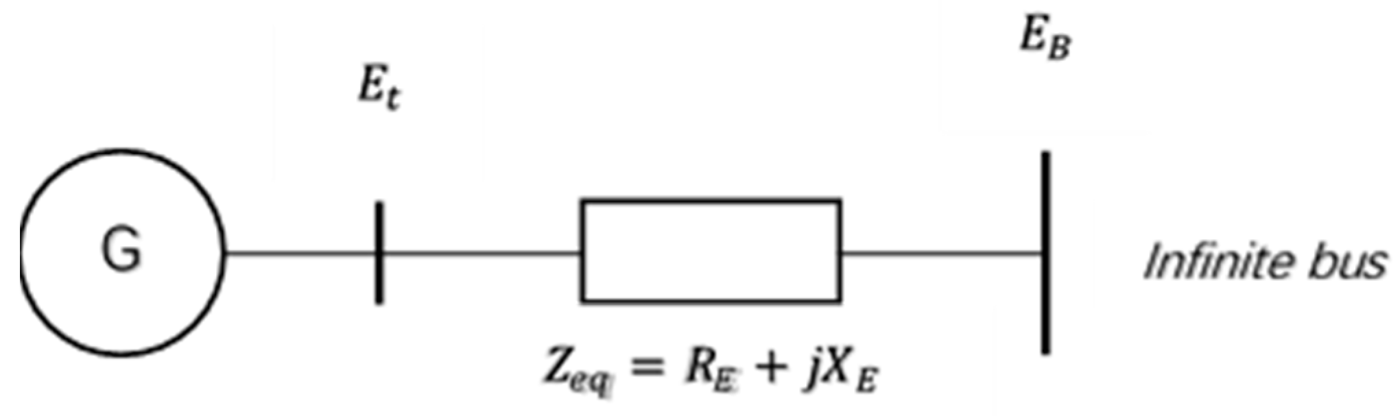


