1. Introduction
Modern technical systems, due to the high concentration of energy, require the use of systems that allow an efficient removal of heat energy. One of the most effective elements for transporting heat energy are so-called heat pipes. The principle of heat pipe operation is based on the use of the phase change material (PCM) phenomenon transporting heat in a confined space. This space is divided into a section within which evaporation takes place (the evaporator), an adiabatic space, and a condensation space called the condenser. The transport of thermal energy takes place from the evaporator to the condenser. The liquid working medium changes its state of aggregation under the influence of the heat of vaporisation. Under the influence of gravitational forces, the medium travels from its gaseous form through the heat pipe towards the condenser, where it changes back into its liquid state. This is accompanied by heat dissipation from the system. The mathematical models of heat transfer through heat pipes have been detailed in paper [
1].
Current research on the development of heat transport systems using a PCM in the form of heat pipes and their use in technology can be divided into several main areas. These are studies on the geometric structure, the type and amount of the working medium, the use of different PCMs, and the modelling of flow visualisation and heat transfer features of heat pipes.
The authors of [
2,
3,
4] analysed the impact of the ratio of the volume of the evaporator to working mediums such as R-134a, acetone, cyclopentane, and n-hexane, on the thermal efficiency of the heat pipe. The adiabatic section, the length of the heat pipes, and the efficiency as a function of the inclination angle were studied. The results obtained show a significant effect of the ratio of the heat pipe volume to the amount of the working medium. The best results were obtained for 15% filling with R-134a, while the tests using acetone indicated an optimum filling of 74%. It was also observed that the length of the adiabatic section did not significantly affect the performance of the heat pipe.
Studies on the construction of heat pipes were also presented in [
5,
6]. A heat pipe solution in the form of a “Pulsating Heat Pipe” was subjected to tests. A pulsating heat pipe is a special type of heat pipe, as it has a fork shape (
Figure 1). In contrast to the standard geometric structure, tests performed with water, ethanol, and methyl alcohol indicated similar thermal properties in this system, especially under a significant heat load. Furthermore, it is possible to obtain heat conduction properties under anti-gravity conditions.
Tests conducted on the degree of filling and the type of working medium used in miniature heat pipes are presented in [
7,
8]. The substances that were analysed included water, acetone, and methanol. The lowest value of thermal resistance was obtained when acetone and ethanol were used at 100% of the evaporator’s volume. When water was used, the highest heat transport coefficient was achieved when 85% of the evaporator volume was filled.
Research related to the modification of the geometric structure of the pulsating heat pipe has been presented in [
9]. The authors developed a harp design for a heat pipe system that was tested using acetone and ethanol. The experimental research results showed that the system efficiency was high at low heat pipe inclination angles.
The use of heat-pipe-type elements in flat solar collectors is presented in [
10]. The authors tested heat pipes with different cross-section shapes for the removal of heat from a solar collector. Circular, elliptical, and semi-circular cross-sections were analysed (
Figure 2). The results obtained showed that the elliptical cross-section heat pipe had the highest efficiency. In addition, the authors showed a correlation between the shape of the cross-section of the heat pipe and the amount of working medium with which it should be filled. The main conclusion was that the optimum amount of the working medium for the elliptical cross-section is 10% of the total volume of the heat pipe, while for the circular cross-section, this value is nearly 20%.
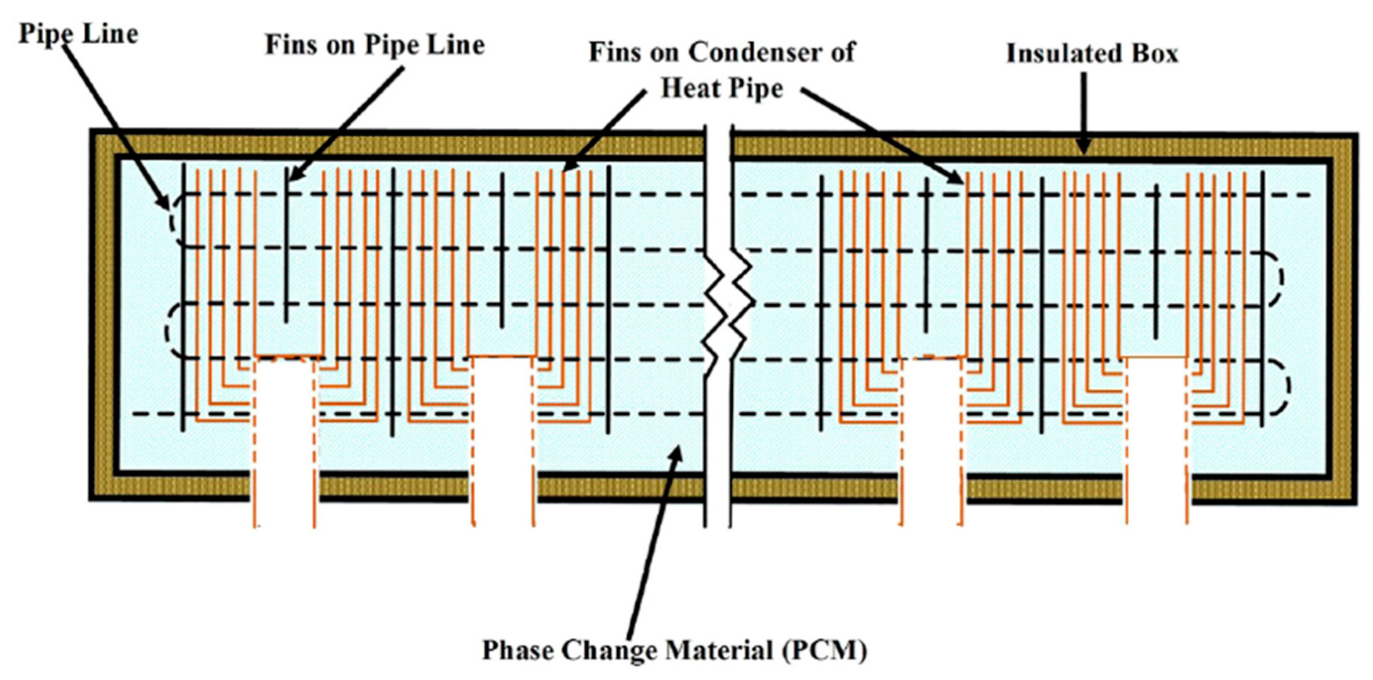
Solar thermal systems suffer from the following two main problems related to the operation of heat pipes: the heat pipe overheating and a low thermal conductivity of the phase change materials. An interesting way to eliminate these problems is to use a manifold filled with stearic acid as a heat storage material [
11]. A prototype of such a system is presented in
Figure 3.
This solution enables efficient heat transport to the PCM through the copper fins. Due to its high heat capacity, it does not lead to the overheating of the heat pipes. The use of paraffin in solar collectors and thermal energy storage containers is also presented in [
12]. The obtained test results confirmed the possibility of eliminating the overheating of vacuum tubes.
In practice, the use of heat pipes covers an increasingly wide range of equipment and technological processes. An interesting example of the innovative application of heat pipes is waste heat recovery in ventilation systems. The author of [
13] presented a prototype of a recuperator with an air-to-air heat exchanger in which the thermal energy of the exhaust stream is transferred through heat pipes to the supply air stream. The recuperator prototype presented by the author enables heat recovery from air and other high temperature gases.
Another innovative idea is the use of heat pipes in machining. The authors of [
14] presented a prototype milling tool with an integrated internal heat removal unit in the cutting zone. Based on the research carried out, it was found that it is possible to increase cutting efficiency and extend tool life by about 50% by lowering the temperature in the machining zone. Another interesting application is in transport infrastructure and the heating of railway and tram turnouts. This issue is discussed in the last part of this article.
Research on heat pipes covers many areas of technology. A review of previous research confirms the important role of these components in innovative technological implementations. The direction of this work can be divided into three main research areas. Publications on heat pipes grouped into these research areas are shown in
Table 1.
The main purpose of this work is to identify the causes of malfunctions in the evacuated tube solar collector. To achieve this goal, a diagnostic procedure was developed, which consists of testing the efficiency of the heat pipes based on infrared imaging of the manifold, measuring the condenser’s temperature during steady-state heat transfer tests in the open tank, and analysing the internal heat pipe structure.
The following activities were planned as part of the diagnostic work: inspection of the heat pipes taken for testing, tests of thermal efficiency characteristics, research on temperature distribution on the solar collector manifold, research on the geometric structure of the heat pipe, and filling with the working medium.
This article is divided into six sections. The remainder of the paper is organised as follows:
Section 2 presents the characteristics of the tested vacuum tube solar collector. The test stand and the method of conducting the research are described in
Section 3. The obtained results are presented in
Section 4, while
Section 5 contains a discussion of the obtained results and a description of additional chemical analysis of the working medium. The article ends with the conclusions presented in
Section 6.
2. Materials and Methods
This research was carried out at the request of one of the Polish companies distributing solar heating systems. The heat pipe solar collector unit delivered for testing showed low thermal efficiency according to the customer. The technical customer service confirmed these observations. Therefore, the manufacturer replaced the device and then asked the Laboratory of Solar Collectors at the Koszalin University of Technology to perform diagnostic tests on the faulty solar collector.
According to the manufacturer, the solar collector submitted for testing does not reach the nominal values of operating parameters. In addition, the performance of the collector is affected by shaking it violently. Such unusual symptoms prompted the manufacturer to undertake diagnostic activities in cooperation with the Koszalin University of Technology.
The solar collector delivered to the laboratory was subjected to a preliminary assessment of its technical condition and visual inspection. This assessment did not reveal any significant mechanical defects or manufacturing errors that could explain the noted dysfunctions of the specimen.
Figure 4 shows the solar collector submitted for testing.
The gross area of the solar collector is 4.3 m
2, and the absorber area is 3 m
2. The total weight of the unfilled collector is 87 kg. The device consists of an insulated manifold that removes heat from the heat pipe condensers. In the manifold, 20 vacuum tubes (
Figure 5), 65 mm in diameter and 1765 mm long, are installed in parallel.
The vacuum tubes are made of 1.8 mm thick tempered solar glass. Inside the tubes there are flat copper absorbers with a thickness of 0.2 mm, that are sputtered with selective coating with an absorption and emission of 95% and 5%, respectively. The thermal efficiency characteristic of the solar collector as declared by the manufacturer is shown in
Figure 6.
3. Experimental Setup
The collector tests were carried out on the test stand for field tests of solar collectors in the Laboratory of Solar Collectors at the Koszalin University of Technology.
Prior to the actual measurements, a visual inspection and recording of the samples submitted for testing were performed. The external surface of the samples was also cleaned, inspected for visible damage, and each vacuum tube was weighed.
The scope of work included a measurement of the thermal characteristics of the diagnosed specimen. In order to perform research on the thermal characteristics of the heat pipe collector, a test stand was constructed (
Figure 7). It consisted of a system for the stabilisation of working medium parameters, a data acquisition system, and a rotating platform for outdoor testing.
The hydraulic circuit worked together with a temperature stabilisation system (TSS) of the working medium. This allowed the solar collector to be supplied with a specific, stable temperature. The working medium (water) was prepared in the water tank (WT) with a capacity of 400 dm3. The mass flow rate of the collector feed was measured using an electromagnetic flow meter (FM1), while the temperature of the working medium was measured using an RTD sensor near the collector feed connector and at the collector outlet (Tin and Tout). The solar radiation intensity at the collector plane was recorded using a LP-PYRA02(PR) pyranometer, while the air parameters surrounding the collector were recorded using a LAMBRECHT14567(AN) anemometer.
The hydraulic system cooperated with an outdoor platform (
Figure 8), which allowed for the inclination angle βc and azimuth γs angle of the solar collector to be changed.
The values of the measured quantities were recorded using an NI-DAQ measurement card module. The accuracy of the measuring instruments used is shown in
Table 2. The atmospheric conditions during the outdoor measurements are presented in
Table 3.
The diagnostic tests performed were extended to include heat transfer measurements in the heat pipes removed from the vacuum tubes. These tests were performed by immersing the heat pipes in a water bath of a known temperature and then taking temperature measurements on the surface of the condensers. In order to ensure a uniform and constant water temperature in the open tank during the tests, the medium was forced to circulate in cooperation with the TSS system. The surface temperature of the condensers was recorded using a thermal imaging camera after applying a coating of a known emissivity εp to the condensers.
Figure 9 shows a diagram of a test stand for heat transfer efficiency in heat pipes.
The heat pipes subjected to the tests were placed successively in an open tank. After a steady state was achieved, the temperature value on the surface of the condensers was recorded. The heat pipe test stand is shown in
Figure 10.
4. Results
The evaluation of the technical condition of the supplied solar collector was carried out by testing the thermal efficiency characteristics. The solar collector was placed on an outdoor measurement platform in a south orientation at an inclination angle of βc = 40°. A measurement of the thermal efficiency of the solar collector was performed according to the requirements of ISO 9806:2017 [
42] at a steady state. The values of the results obtained at individual measurement points were approximated to a second-degree polynomial curve using the least squares method [
43], as follows:
The results of the solar collector thermal efficiency measurements are shown in
Figure 11.
Table 4 presents a comparison of the thermal efficiency curve coefficients resulting from measurements and values declared by the manufacturer.
The obtained results of the study of the thermal efficiency characteristics of the solar collector indicate a discrepancy between the experimental values and those declared by the manufacturer. Both the value of the optical efficiency coefficient as well as the thermal loss coefficients and indicate a reduction in energy efficiency resulting from the incorrect operation of the collector.
In order to determine the reasons for the malfunctioning of the tested object, the temperature distribution on the manifold surface was tested. To be able to correctly determine the temperature distribution on the surface of the manifold, its external surface was covered with a coating of a known emissivity εm, which required the disassembly of the insulated housing. The thermal imaging camera was then calibrated. A manifold with a coating of a known emissivity (εm = 0.97) is shown in
Figure 12.
The temperature distribution on the surface of the manifold condenser sockets was measured by taking two thermograms, one after the other (
Figure 13), at a thermal equilibrium state during a given measurement period. The temperature values of each measurement point on the manifold surface were averaged from an area covering half of the outer circumference of each condenser socket. FLIR QuickPlot software was used to process the results from the thermograms.
A series of measurements were performed for three different solar collector inclination angles β (20°, 40° and 60°). A series of thermograms were taken for each collector position, and then the temperature values were averaged for each evaporator socket. The results are shown in
Figure 14.
The graph shows the temperature values on the following heat pipe sockets: Socket 1 is located near the working medium entrance to the solar collector, while Socket 20 is the last socket before the medium exits the collector. The dashed line in
Figure 14 illustrates the approximated temperature distribution of the medium between the input and output of the solar collector. It determines the approximate value of the medium temperature along the manifold, assuming an equal linear temperature rise. In fact, the temperature of the medium along the manifold is not linear and depends on the efficiency of the individual vacuum tubes. However, such an assumption allows for an evaluation of the correct operation of each vacuum tube. By referring the temperature measured at the pipe socket to an assumed simple input–output temperature distribution, the energy efficiency of each of the 20 vacuum pipes tested can be determined. The greater the difference between the evaporator socket temperature and the approximate local temperature of the medium in the manifold is, the higher the thermal efficiency of a given vacuum tube is.
Based on the results of the thermographic examination of the manifold, nine vacuum tubes of the lowest efficiency were selected, i.e., tubes 2, 4, 6, 8, 11, 13, 14, 18, and 19.
By evaluating the sputtering condition of the getter (vacuum gauge), the vacuums in each tube were found to be normal (approximately 0.1 Pa). This ruled out defective thermal insulation in the heat pipes.
In order to ensure uniform test conditions for each sample, an open tank test stand was prepared. The samples were unsealed and taken out of the glass tubes. A coating of a known emissivity (εp = 0.97) was applied to the evaporator surfaces. Next, the temperature distribution on the surface of the heat pipe evaporators immersed in a hot water bath was investigated. Such activity was designed to evaluate the ability of heat pipes to transport thermal energy from the water tank to the environment. A summary of the thermograms for each of the nine samples tested is shown in
Figure 15.
For each test sample, the tank’s water temperature and the condenser’s surface temperature were measured after a steady state had been obtained. The temperature difference ΔT between the heating fluid surrounding the evaporator T
z and the condenser’s surface temperature T
s is proportional to the heat pipe’s ability to transport thermal energy. The lower the ΔT value is, the higher the performance of the heat pipe is. The ΔT values calculated for each of the tested heat pipes are summarised in
Table 5.
The samples numbered 2, 8, and 11 showed the best heat conductivity properties because the difference between the condenser and evaporator temperatures was the smallest. The samples numbered 4, 6, 18, and 19 turned out to be the worst in terms of thermal conductivity.
Figure 16 shows a summary of the heat pipe test results.
Then, the geometric structure of the heat pipes was visually inspected, and tests were carried out to analyse the influence of individual geometric features on the extent of the heat pipe’s correct operation. To visually inspect the internal surfaces of the heat pipes, individual sections of the samples were incised, and their internal structure was analysed. The appearance of the heat pipes after cutting is shown in
Figure 17.
The working media of the heat pipes were decanted into measuring cylinders. The volume measurement was performed at 20 °C. The measurement results are shown in
Figure 18.
5. Discussion
The experimental work carried out and the results obtained allowed for the formulation of the following conclusions:
Based on the study of the thermal efficiency characteristics (
Figure 19), it was confirmed that the solar collector transferred for testing did not reach the nominal operating parameters. The thermal efficiency characteristics performed under natural conditions were clearly below the nominal value declared by the manufacturer. The optical efficiency of the tested unit was 15% lower than the efficiency stated on the product data sheet. The values of heat loss coefficients
and
were higher by 49% and 17%, respectively. The results obtained confirmed the existence of malfunctions in the functioning of the tested specimen.
The thermographic study of the manifold made it possible to observe the temperature distribution on the surfaces of the heat pipe sockets. In the presented measurement results, the temperature of the input and output fluid from the collector was connected by a straight line. Such a representation of the results is a significant simplification and does not represent the real values of the fluid temperature in the individual manifold sections since the fluid going through the manifold does not obtain heat energy in a linear manner. However, for determining values to compare the performance of individual solar collector fins, this simplification was considered reasonable. The temperatures of the sockets cooperating with pipes 2, 4, 6, 8, 11, 13, 14, 18, and 19 were close to the local medium temperature, indicating their low efficiency.
In order to eliminate the design error of the manifold (differences in thermal contact between individual sockets and condensers), the tests were repeated for several different vacuum tube configurations. This allowed for the detection of differences in the effectiveness of the vacuum tubes. Based on these tests, the least efficient samples for further tests were selected. Ultimately, nine vacuum tubes found to be defective were designated for further diagnostic testing, which accounted for 45% of the total sample.
The measurements of the working fluid volume in the heat pipes showed significant discrepancies between the samples. The proper functioning of the heat pipe requires that the evaporator volume of 5 mL be 85% full. In samples 2, 6, and 13, the amount of working medium was over 4 mL, while in samples 2, 8, 11, 14, and 18 the amount of medium oscillated around the value of 2 mL, which is only 40% of the evaporator volume. The worst in this respect was sample 19, in which the amount of working fluid was only 24% of the evaporator volume. In addition, a chemical analysis of the working medium used was carried out (
Figure 20). These tests excluded the presence of acetone and methyl alcohol. The basic chemical composition of the medium in the form of demineralised water with corrosion inhibitor additives was established.
During diagnostic testing of the internal structure of the heat pipes, a design irregularity was observed in the condenser section. The design defect detected was the result of an incorrect connection between the condenser tank and the evaporator pipe in the soldering operation (
Figure 21 and
Figure 22).
The detected installation irregularity, consisting of the condenser being seated too deep, occurred in four of the nine (44.4%) samples tested, i.e., sample 4, 6, 11, and 13. As a result, suspension of the working fluid inside the condenser may occur (
Figure 23), and thus cause a significant reduction in the efficiency of the heat pipe.
The observed design defect was the condenser being seated too deep on the adiabatic conduit, which may cause a drop of the working liquid to hang in the evaporator, preventing its passage into the evaporator section.
The results of the diagnostic tests are summarised in
Table 6.
6. Conclusions
Diagnostic tests on a selected group of vacuum tubes confirmed the presence of structural defects. Design defects observed included the improper seating of the condenser on the neck of the adiabatic section and the improper filling of the heat pipe with the working medium. Irregularities in the form of improper installation of the heat pipe were diagnosed in four of the nine samples, while improper filling of the heat pipe was noted in six of the nine samples. The results clearly show that the functioning of the heat pipe significantly depends on its geometric structure and the amount of working medium. Any irregularity at the production stage contributes to a reduction in the thermal efficiency of the solar collector.
The elimination of the malfunctions indicated as a result of the diagnostic procedure will significantly reduce the number of product complaints. This, in turn, has a direct impact on the financial results achieved by the manufacturer. Ultimately, this may result in a lower unit price for the customer.
The diagnostic procedure scheme presented in this paper can be used to analyse solar systems and the organisation of solar collector manufacturing processes. The main advantages of this approach are high precision and certainty of the achieved results. The most significant disadvantage of this method is the necessity to disassemble the tested samples, making it impossible to conduct other comparative tests.
Directions for further research in diagnostics and the performance evaluation of solar systems will also include the identification of the thermophysical parameters of selective coatings, spectral transmittance analysis of glass, and broader analysis of the chemical composition of the working fluid for the high thermal efficiency of the heat pipes.
The results presented in this paper are of great importance in device diagnostics and the evaluation of the quality and feasibility of their implementation. Future action plans include extending the scope of the laboratory for the maintenance of rail transport infrastructure held at the Faculty of Transport of the Warsaw University of Technology by constructing turnout elements with a built-in turnout heating system using solar collectors. The use of the obtained results and the developed test procedure will allow extended research to assess the scale of the impact of structural imperfections on alternative energy sources in practical applications.
Author Contributions
Conceptualization, P.Z., K.K., N.C.-G., E.S. and J.K.; methodology, P.Z. and K.K.; software, P.Z. and K.K.; validation, P.Z., K.K. and N.C.-G.; formal analysis, P.Z., K.K., N.C.-G., J.K. and E.S.; resources, P.Z., K.K., N.C.-G. and E.S.; data curation, P.Z. and K.K.; writing—original draft preparation, P.Z. and K.K.; writing—review and editing, P.Z., K.K., N.C.-G., E.S. and J.K.; visualization, P.Z. and K.K.; supervision, N.C.-G., E.S. and J.K.; funding acquisition, E.S. and J.K. All authors have read and agreed to the published version of the manuscript.
Funding
This research was funded by the Warsaw University of Technology within the IDUB-Open Science Program.
Institutional Review Board Statement
Not applicable.
Informed Consent Statement
Informed consent was obtained from all subjects involved in the study.
Data Availability Statement
Data available in a publicly accessible repository.
Acknowledgments
The authors would like to gratefully acknowledge the reviewers that provided helpful comments and insightful suggestions on a draft of the manuscript.
Conflicts of Interest
The authors declare no conflict of interest. The funders had no role in the design of the study; in the collection, analyses, or interpretation of the data; in the writing of the manuscript; or in the decision to publish the results.
References
- Al Jubori, A.M.; Jawad, Q.A. Computational evaluation of thermal behavior of a wickless heat pipe under various conditions. Case Stud. Therm. Eng. 2020, 22, 100767. [Google Scholar] [CrossRef]
- Sukchana, T.; Jaiboonma, C. Effect of Filling Ratios and Adiabatic Length on Thermal Efficiency of Long Heat Pipe Filled with R-134a. Energy Procedia 2013, 34, 298–306. [Google Scholar] [CrossRef] [Green Version]
- Huang, G.; Tang, Y.; Wang, P.; Lu, L.; Yuan, W. Thermal Characterisation of Micro Flat Aluminium Heat Pipe Arrays by Varying Working Fluid and Inclination Angle. Appl. Sci. 2018, 8, 1052. [Google Scholar] [CrossRef] [Green Version]
- Andrzejczyk, R. Experimental Investigation of the Thermal Performance of a Wickless Heat Pipe Operating with Different Fluids: Water, Ethanol, and SES36. Analysis of Influences of Instability Processes at Working Operation Parameters. Energies 2018, 12, 80. [Google Scholar] [CrossRef] [Green Version]
- Barua, H.; Ali, M.; Nuruzzaman, M.; Islam, Q.; Feroz, C.M. Effect of Filling Ratio on Heat Transfer Characteristics and Per-formance of a Closed Loop Pulsating Heat Pipe. Procedia Eng. 2013, 56, 88–95. [Google Scholar] [CrossRef] [Green Version]
- Tseng, C.-Y.; Yang, K.-S.; Wang, C.-C. Non-Uniform Three-Dimensional Pulsating Heat Pipe for Anti-Gravity High-Flux Applications. Energies 2020, 13, 3068. [Google Scholar] [CrossRef]
- Mozumder, A.K.; Akon, A.F.; Chowdhury, M.S.H.; Banik, S.C. Performance of Heat Pipe for Different Working Fluids and Fill Ratios. J. Mech. Eng. 2011, 41, 96–102. [Google Scholar] [CrossRef] [Green Version]
- Winkler, M.; Rapp, D.; Mahlke, A.; Zunftmeister, F.; Vergez, M.; Wischerhoff, E.; Clade, J.; Bartholomé, K.; Schäfer-Welsen, O. Small-Sized Pulsating Heat Pipes/Oscillating Heat Pipes with Low Thermal Resistance and High Heat Transport Capability. Energies 2020, 13, 1736. [Google Scholar] [CrossRef] [Green Version]
- Shen, C.; Zhang, Y.; Wang, Z.; Zhang, D.; Liu, Z. Experimental investigation on the heat transfer performance of a flat parallel flow heat pipe. Int. J. Heat Mass Transf. 2021, 168, 120856. [Google Scholar] [CrossRef]
- Hussein, H.; El-Ghetany, H.; Nada, S. Performance of wickless heat pipe flat plate solar collectors having different pipes cross sections geometries and filling ratios. Energy Convers. Manag. 2006, 47, 1539–1549. [Google Scholar] [CrossRef]
- Chopra, K.; Tyagi, V.; Pathak, A.K.; Pandey, A.; Sari, A. Experimental performance evaluation of a novel designed phase change material integrated manifold heat pipe evacuated tube solar collector system. Energy Convers. Manag. 2019, 198, 111896. [Google Scholar] [CrossRef]
- Alshukri, M.J.; Eidan, A.A.; Najim, S.I. Thermal performance of heat pipe evacuated tube solar collector integrated with different types of phase change materials at various location. Renew. Energy 2021, 171, 635–646. [Google Scholar] [CrossRef]
- Elmas, E.T. Design and production of high temperature heat pipe heat recovery units. J. Mol. Struct. 2020, 1212, 127927. [Google Scholar] [CrossRef]
- Uhlmann, E.; Riemer, H.; Schröter, D.; Sammler, F.; Richarz, S. Substitution of Coolant by Using a Closed Internally Cooled Milling Tool. Procedia CIRP 2017, 61, 553–557. [Google Scholar] [CrossRef]
- Esmaeilzadeh, A.; Silakhori, M.; Ghazali, N.N.N.; Metselaar, H.S.C.; Bin Mamat, A.; Sanjani, M.S.N.; Iranmanesh, S. Thermal Performance and Numerical Simulation of the 1-Pyrene Carboxylic-Acid Functionalized Graphene Nanofluids in a Sintered Wick Heat Pipe. Energies 2020, 13, 6542. [Google Scholar] [CrossRef]
- Hansen, G.; Næss, E.; Kristjansson, K. Analysis of a Vertical Flat Heat Pipe Using Potassium Working Fluid and a Wick of Compressed Nickel Foam. Energies 2016, 9, 170. [Google Scholar] [CrossRef] [Green Version]
- Kujawska, A.; Zajaczkowski, B.; Wilde, L.; Buschmann, M. Geyser boiling in a thermosyphon with nanofluids and surfactant solution. Int. J. Therm. Sci. 2019, 139, 195–216. [Google Scholar] [CrossRef]
- Maddah, H.; Ghazvini, M.; Ahmadi, M.H. Predicting the efficiency of CuO/water nanofluid in heat pipe heat exchanger using neural network. Int. Commun. Heat Mass Transf. 2019, 104, 33–40. [Google Scholar] [CrossRef]
- Ramkumar, P.; Sivasubramanian, M.; Raveendiran, P.; Kanna, P.R. An experimental inquisition of waste heat recovery in electronic component system using concentric tube heat pipe heat exchanger with different working fluids under gravity assistance. Microprocess. Microsystems 2021, 83, 104033. [Google Scholar] [CrossRef]
- Song, E.-H.; Lee, K.-B.; Rhi, S.-H.; Kim, K. Thermal and Flow Characteristics in a Concentric Annular Heat Pipe Heat Sink. Energies 2020, 13, 5282. [Google Scholar] [CrossRef]
- Tariq, S.L.; Ali, H.M.; Akram, M.A.; Janjua, M.M.; Ahmadlouydarab, M. Nanoparticles enhanced phase change materials (NePCMs)—A recent review. Appl. Therm. Eng. 2020, 176, 115305. [Google Scholar] [CrossRef]
- Xiong, Y.; Wang, Z.; Wu, Y.; Xu, P.; Ding, Y.; Chang, C.; Ma, C. Performance enhancement of bromide salt by nano-particle dispersion for high-temperature heat pipes in concentrated solar power plants. Appl. Energy 2019, 237, 171–179. [Google Scholar] [CrossRef]
- Yang, K.-S.; Jiang, M.-Y.; Tseng, C.-Y.; Wu, S.-K.; Shyu, J.-C. Experimental Investigation on the Thermal Performance of Pulsating Heat Pipe Heat Exchangers. Energies 2020, 13, 269. [Google Scholar] [CrossRef] [Green Version]
- Abokersh, M.; El-Morsi, M.; Sharaf, O.; Abdelrahman, W. On-demand operation of a compact solar water heater based on U-pipe evacuated tube solar collector combined with phase change material. Sol. Energy 2017, 155, 1130–1147. [Google Scholar] [CrossRef]
- Essa, M.A.; Mostafa, N.H.; Ibrahim, M.M. An experimental investigation of the phase change process effects on the system performance for the evacuated tube solar collectors integrated with PCMs. Energy Convers. Manag. 2018, 177, 1–10. [Google Scholar] [CrossRef]
- Faegh, M.; Shafii, M.B. Experimental investigation of a solar still equipped with an external heat storage system using phase change materials and heat pipes. Desalination 2017, 409, 35–128. [Google Scholar] [CrossRef] [Green Version]
- Feliński, P.; Sekret, R. Effect of a low cost parabolic reflector on the charging efficiency of an evacuated tube collector/storage system with a PCM. Sol. Energy 2017, 144, 758–766. [Google Scholar] [CrossRef]
- Li, B.; Zhai, X.; Cheng, X. Experimental and numerical investigation of a solar collector/storage system with composite phase change materials. Sol. Energy 2018, 164, 65–76. [Google Scholar] [CrossRef]
- Papadimitratos, A.; Sobhansarbandi, S.; Pozdin, V.; Zakhidov, A.; Hassanipour, F. Evacuated tube solar collectors integrated with phase change materials. Sol. Energy 2016, 129, 9–10. [Google Scholar] [CrossRef] [Green Version]
- Wei, W.; Suzhou, D.; Zundi, L.; Yiping, D.; Junye, H.; Mengyang, L. Experimental study on the performance of a novel solar water heating system with and without PCM. Sol. Energy 2018, 171, 12–604. [Google Scholar]
- Almahmoud, S.; Jouhara, H. Experimental and theoretical investigation on a radiative flat heat pipe heat exchanger. Energy 2019, 174, 972–984. [Google Scholar] [CrossRef]
- Belhocine, A. Numerical study of heat transfer in fully developed laminar flow inside a circular tube. Int. J. Adv. Manuf. Technol. 2016, 85, 2681–2692. [Google Scholar] [CrossRef]
- Belhocine, A.; Wan Omar, W.Z. An analytical method for solving exact solutions of the convective heat transfer in fully de-veloped laminar flow through a circular tube. Heat Trans. Asian Res. 2017, 46, 1342–1353. [Google Scholar] [CrossRef]
- Belhocine, A.; Omar, W.W. Numerical study of heat convective mass transfer in a fully developed laminar flow with constant wall temperature. Case Stud. Therm. Eng. 2015, 6, 116–127. [Google Scholar] [CrossRef] [Green Version]
- Brahim, T.; Jemni, A. Numerical case study of packed sphere wicked heat pipe using Al 2 O 3 and CuO based water nanofluid. Case Stud. Therm. Eng. 2016, 8, 311–321. [Google Scholar] [CrossRef] [Green Version]
- Fadhl, B.; Wrobel, L.C.; Jouhara, H. Numerical modelling of the temperature distribution in a two-phase closed thermosyphon. Appl. Therm. Eng. 2013, 60, 122–131. [Google Scholar] [CrossRef] [Green Version]
- Jung, E.G.; Boo, J.H. A Novel Analytical Modeling of a Loop Heat Pipe Employing the Thin-Film Theory: Part I—Modeling and Simulation. Energies 2019, 12, 2408. [Google Scholar] [CrossRef] [Green Version]
- Jung, E.G.; Boo, J.H. A Novel Analytical Modeling of a Loop Heat Pipe Employing Thin-Film Theory: Part II—Experimental Validation. Energies 2019, 12, 2403. [Google Scholar] [CrossRef] [Green Version]
- Kudela, L.; Chylek, R.; Pospisil, J. Performant and Simple Numerical Modeling of District Heating Pipes with Heat Accumulation. Energies 2019, 12, 633. [Google Scholar] [CrossRef] [Green Version]
- Rosenberg, D. Methods for the Numerical Solution of Partial Differential Equations; American Elsevier Publishing Co.: New York, NY, USA, 1969. [Google Scholar]
- Wang, X.; Wang, Y.; Chen, H.; Zhu, Y. A combined CFD/visualization investigation of heat transfer behaviors during geyser boiling in two-phase closed thermosyphon. Int. J. Heat Mass Transf. 2018, 121, 703–714. [Google Scholar] [CrossRef]
- ISO 9806:2017. Solar Energy-Solar Thermal Collectors—Test Methods. Approach. Stand.; European Committee for Standardizations: Brussels, Belgium, 2017. [Google Scholar]
- Kamiński, K.; Krzyżyński, T. Modeling and Simulation of the Solar Collector Using Different Approaches. Artif. Intell. Comput. Softw. Eng. Adv. 2016, 414, 131–151. [Google Scholar] [CrossRef]
Figure 1.
Pulsating heat pipe [
5].
Figure 1.
Pulsating heat pipe [
5].
Figure 2.
Cross-sectional views of the prototype wickless heat pipe flat plate solar collector [
10].
Figure 2.
Cross-sectional views of the prototype wickless heat pipe flat plate solar collector [
10].
Figure 3.
Design of phase change material integrated manifold [
11].
Figure 3.
Design of phase change material integrated manifold [
11].
Figure 4.
Vacuum-tube solar collector.
Figure 4.
Vacuum-tube solar collector.
Figure 5.
Construction of the vacuum tube of a solar collector. 1—glass cover; 2—evaporator; 3—adiabatic section; 4—absorber; 5—top cover; 6—condenser.
Figure 5.
Construction of the vacuum tube of a solar collector. 1—glass cover; 2—evaporator; 3—adiabatic section; 4—absorber; 5—top cover; 6—condenser.
Figure 6.
Thermal efficiency characteristic of the the nominal collector.
Figure 6.
Thermal efficiency characteristic of the the nominal collector.
Figure 7.
Test stand diagram.
Figure 7.
Test stand diagram.
Figure 8.
Outdoor platform.
Figure 8.
Outdoor platform.
Figure 9.
The heat transfer test stand diagram. 1—thermally insulated tank; 2—heating fluid (water); 3—heat pipe evaporator; 4—heat pipe condenser; 5—thermal imaging camera; 6—heating liquid temperature sensor; 7—heating liquid inlet pipe; 8—heating liquid outlet pipe.
Figure 9.
The heat transfer test stand diagram. 1—thermally insulated tank; 2—heating fluid (water); 3—heat pipe evaporator; 4—heat pipe condenser; 5—thermal imaging camera; 6—heating liquid temperature sensor; 7—heating liquid inlet pipe; 8—heating liquid outlet pipe.
Figure 10.
The heat transfer test stand.
Figure 10.
The heat transfer test stand.
Figure 11.
Thermal efficiency of the tested solar collector.
Figure 11.
Thermal efficiency of the tested solar collector.
Figure 12.
A manifold with an applied coating of a known emissivity factor εm.
Figure 12.
A manifold with an applied coating of a known emissivity factor εm.
Figure 13.
Thermograms taken during testing of the temperature distribution of the manifold.
Figure 13.
Thermograms taken during testing of the temperature distribution of the manifold.
Figure 14.
Summary of the thermographic tests results of the manifold surface.
Figure 14.
Summary of the thermographic tests results of the manifold surface.
Figure 15.
Thermograms taken during the research.
Figure 15.
Thermograms taken during the research.
Figure 16.
Temperature differences on the condensers and evaporators of individual heat pipes.
Figure 16.
Temperature differences on the condensers and evaporators of individual heat pipes.
Figure 17.
Tested heat pipes after incision.
Figure 17.
Tested heat pipes after incision.
Figure 18.
Results of the working medium volume measurements in the heat pipes.
Figure 18.
Results of the working medium volume measurements in the heat pipes.
Figure 19.
Characteristics of the heat capacity of the collector tested, and the nominal ones based on the data sheet.
Figure 19.
Characteristics of the heat capacity of the collector tested, and the nominal ones based on the data sheet.
Figure 20.
Analysis of the chemical composition of the working medium.
Figure 20.
Analysis of the chemical composition of the working medium.
Figure 21.
Condenser connection to the adiabatic pipe: (a)—correct, (b)—incorrect.
Figure 21.
Condenser connection to the adiabatic pipe: (a)—correct, (b)—incorrect.
Figure 22.
A condenser not properly seated on the adiabatic pipe.
Figure 22.
A condenser not properly seated on the adiabatic pipe.
Figure 23.
Suspension of the working fluid inside the evaporator.
Figure 23.
Suspension of the working fluid inside the evaporator.
Table 1.
Research efforts correlated to selected areas.
Table 1.
Research efforts correlated to selected areas.
| Research Area | Description | Research |
|---|
| Working fluid and geometry | Impact of the geometry of the heat pipe, and the type and amount of the working medium on the thermal properties | [15,16,17,18,19,20,21,22,23] |
| Applications of Phase Change Materials | The use of different PCMs to increase the utility of energy storage systems | [24,25,26,27,28,29,30] |
| Modelling of heat exchange process | Studies on the modelling of the heat exchange process and identifying the flow parameters of the working medium | [31,32,33,34,35,36,37,38,39,40,41] |
Table 2.
Accuracy of measuring instruments.
Table 2.
Accuracy of measuring instruments.
| Measured Quantity | Measuring Instrument | Accuracy of Measurement |
|---|
| Radiation intensity | Pyranometer LP PYRA 02 | +/−25 W/m2 |
| Wind speed | Anemometer
LAMBRECHT 14567 | +/−2% |
| The working medium flow rate | Electromagnetic flow meter ENCO MPP6 | +/−0.5% |
| Inlet temperature | Pt100 | +/−0.1 K |
| Outlet temperature | Pt100 | +/−0.1 K |
| Ambient temperature | Pt100 | +/−0.1 K |
| Inclination angle | Outdoor platform | +/−5° |
| Surface temperature | Thermal imaging camera Flir T-335 | +/−0.1 K |
Table 3.
Outdoor conditions during the thermal efficiency characteristic ηc measurements.
Table 3.
Outdoor conditions during the thermal efficiency characteristic ηc measurements.
| Test Conditions | Value |
|---|
| Global radiation intensity | 950 +/− 50 W/m2 |
| Mass flow rate | 180 kg/h |
| Wind speed | 4 +/− 2 m/s |
| Working medium type | Water |
Table 4.
Coefficients of thermal efficiency characteristics of a solar collector.
Table 4.
Coefficients of thermal efficiency characteristics of a solar collector.
| | | | |
|---|
| The values declared by the manufacturer | 0.8 | 1.16 | 0.006 |
| The values obtained from the measurement | 0.68 | 1.73 | 0.007 |
Table 5.
The results of thermal energy transport test of heat pipes.
Table 5.
The results of thermal energy transport test of heat pipes.
| Sample Number | Heating Fluid
Temperature Tz [°C] | Surface Condenser
Temperature
Ts [°C] | ΔT = Tz − Ts |
|---|
| 2 | 62.9 | 59.9 | 3 |
| 4 | 63 | 58.8 | 4.2 |
| 6 | 62.9 | 58.4 | 4.5 |
| 8 | 63 | 59.9 | 3.1 |
| 11 | 63.1 | 60.1 | 3 |
| 13 | 63 | 58.9 | 4.1 |
| 14 | 62.9 | 58.7 | 4.2 |
| 18 | 63 | 58.2 | 4.8 |
| 19 | 62.9 | 55.8 | 7.1 |
Table 6.
Summary of diagnostic test results.
Table 6.
Summary of diagnostic test results.
| Sample Number | 2 | 4 | 6 | 8 | 11 | 13 | 14 | 18 | 19 |
|---|
| Working fluid volume [mL] | 2.1 | 4.1 | 4.2 | 2 | 2.1 | 4.1 | 2.2 | 2.1 | 1.2 |
| Improper connection of the condenser | NO | YES | YES | NO | YES | YES | NO | NO | NO |
| Publisher’s Note: MDPI stays neutral with regard to jurisdictional claims in published maps and institutional affiliations. |
© 2021 by the authors. Licensee MDPI, Basel, Switzerland. This article is an open access article distributed under the terms and conditions of the Creative Commons Attribution (CC BY) license (https://creativecommons.org/licenses/by/4.0/).


 ,
, 


