
Optimal Battery Energy Storage Dispatch Strategy for Small-Scale Isolated Hybrid Renewable Energy System with Different Load Profile Patterns


Abstract
:
1. Introduction
2. Dispatch Power and Cost Calculation
2.1. BES Available Charge and Discharge Power
2.2. Power Dispatch Setpoints
2.3. Component’s Marginal Cost
2.4. Financial Model
3. Control Strategies
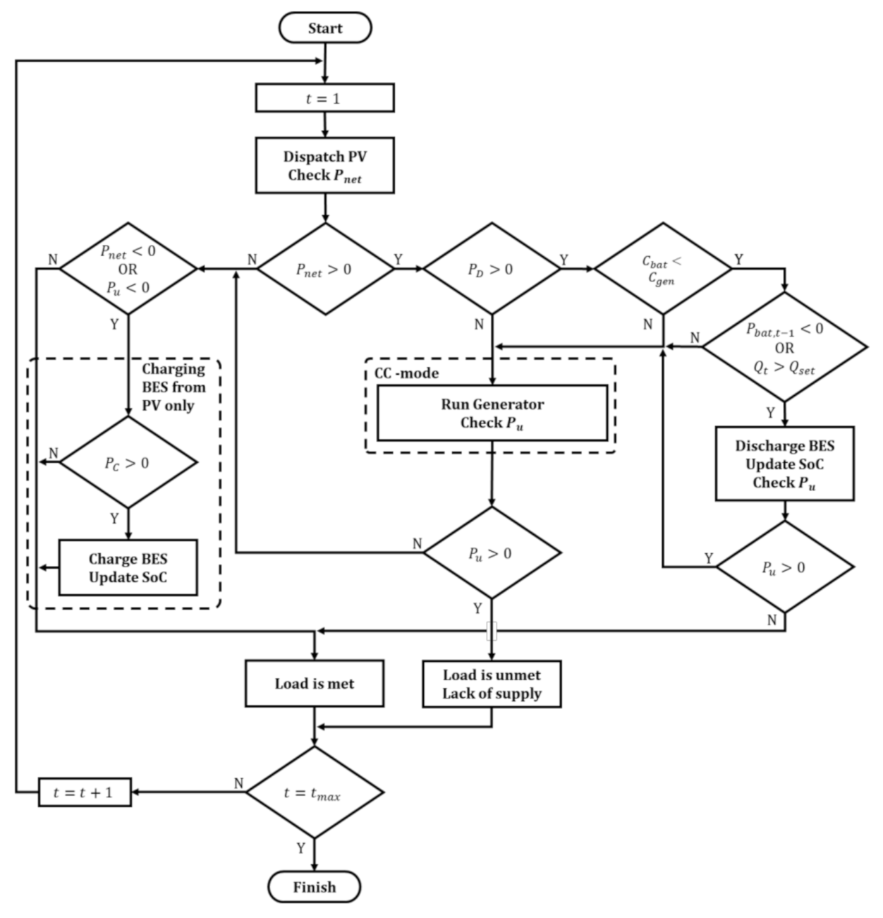
3.1. Load Following
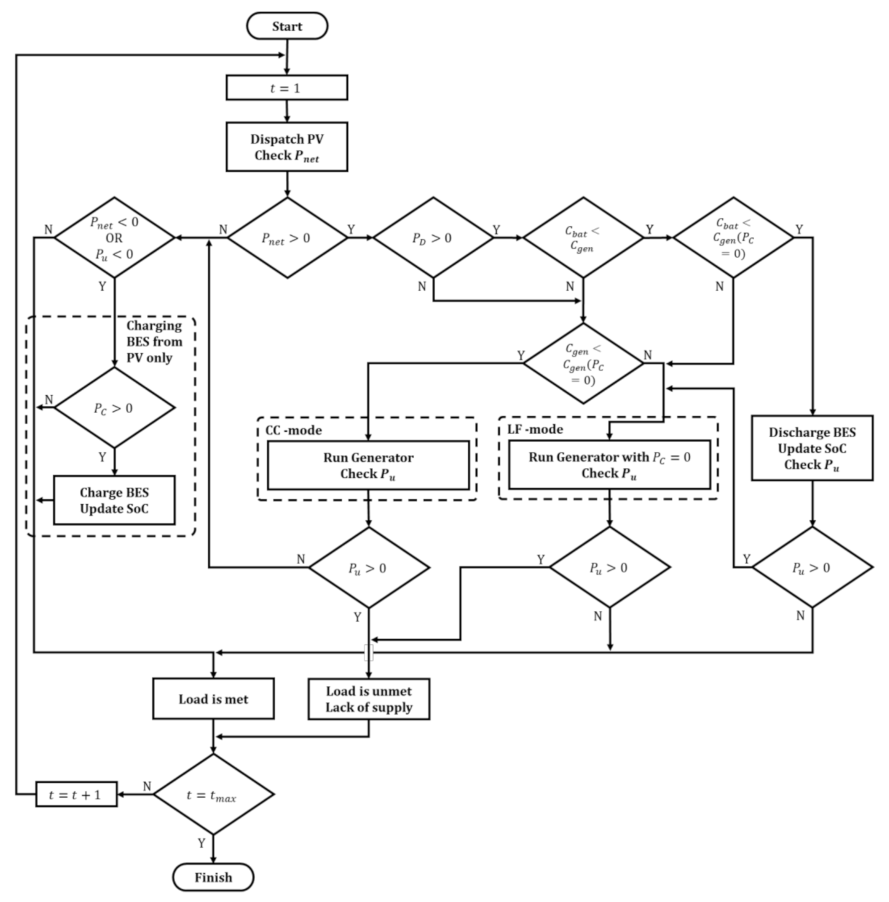
3.2. Cycle Charging
- The battery is discharged in the previous time step ( < 0);
- The SoC is higher than the setpoint SoC ( > ).
3.3. Combined Dispatch
- BES will be discharged if the stored energy in the battery is available ( > 0) and the cost of discharging the battery () is cheaper than the cost of running the generator to supply the load and to charge the battery () and the cost of running the generator only to supply the load ( (at = 0));
- The CC mode control strategy will be applied if the cost of running the generator to supply the load and to charge the battery () is lower than the cost of discharging the battery () and the cost of running the generator only to supply the load ( (at = 0));
- The LF mode control strategy will be applied if the cost of running the generator only to supply the load ( (at = 0)) is cheaper than the cost of discharging the battery () and the cost of running the generator to supply the load and to charge the battery (). Additionally, the LF mode control strategy is also applied if the BES is discharged but cannot satisfy the net required load.
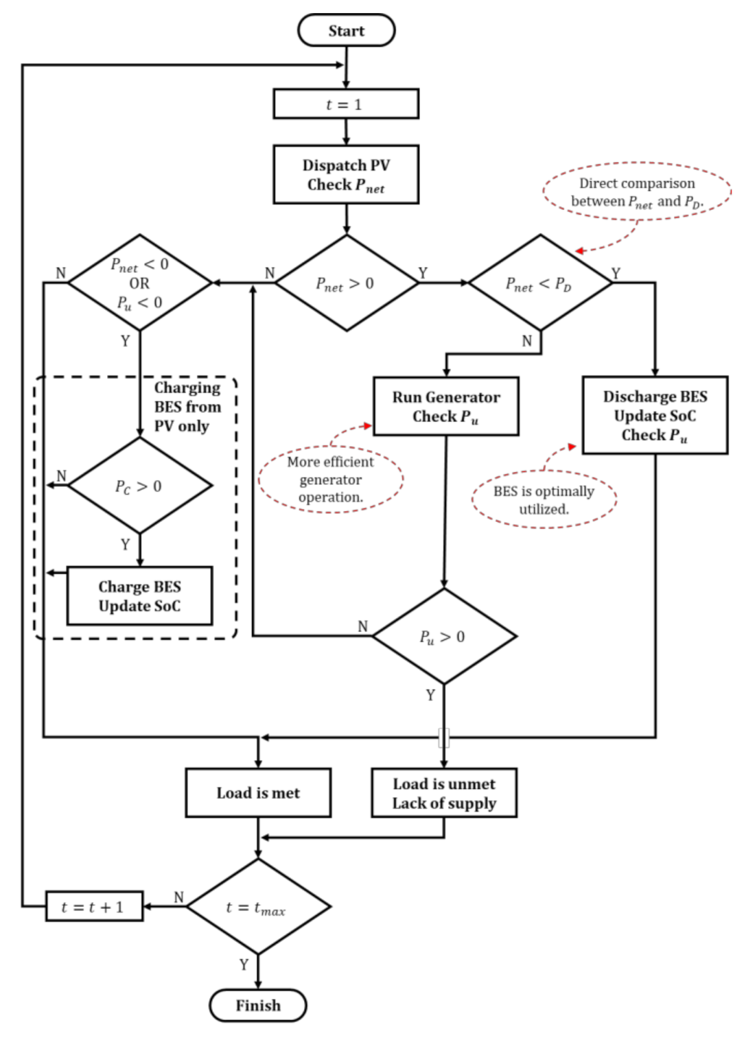
3.4. Optimized BES Discharge (OBD)
4. Simulation and Results
4.1. Systems’ Profile
4.2. Hybrid System Configuration and Component’s Unit Cost
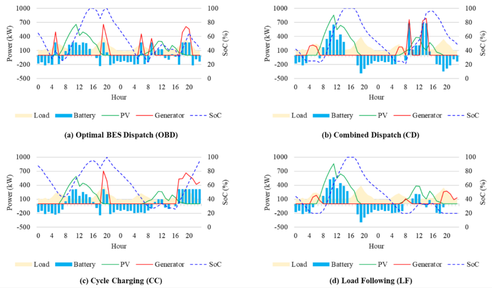
4.3. Simulation Result
4.4. Discussion
5. Conclusions
Author Contributions
Funding
Institutional Review Board Statement
Informed Consent Statement
Data Availability Statement
Acknowledgments
Conflicts of Interest
Nomenclature
| BES | Battery Energy System |
| CC | Cycle Charging |
| CD | Combined Dispatch |
| HOMER | Hybrid Optimization of Multiple Energy Resources |
| HRES | Hybrid Renewable Energy System |
| LCOE | Levelized Cost of Energy |
| LF | Load Following |
| NPC | Net Present Cost |
| OBD | Optimal BES Discharge |
| PV | Photovoltaic |
| RE | Renewable Energy |
| SFC | Specific Fuel Consumption |
| SOC | State of Charge |
References
- Budiyanto, A.; Kamil, M.I.; Aryani, D.R.; Jufri, F.H.; Ardita, I.M. Performance analysis of a hybrid natural gas generator/photovoltaic system for residential use. IOP Conf. Ser. Earth Environ. Sci. 2020, 599, 012018. [Google Scholar] [CrossRef]
- Aprilianti, K.P.; Baghta, N.A.; Aryani, D.R.; Jufri, F.H.; Utomo, A.R. Potential assessment of solar power plant: A case study of a small island in Eastern Indonesia. IOP Conf. Ser. Earth Environ. Sci. 2020, 599, 012026. [Google Scholar] [CrossRef]
- Garniwa, I.; Herdiansyah, H. Sustainability Index of Solar Power Plants in Remote Areas in Indonesia. Technol. Econ. Smart Grids Sustain. Energy 2021, 6, 1–14. [Google Scholar]
- Government of Indonesia. Keputusan Menteri Energi dan Sumber Daya Mineral Republik Indonesia No. 55K/20/MEM/2019 tentang Besaran Biaya Pokok Penyediaan Pembangkitan PT Perusahaan Listrik Negara (Persero) Tahun 2018; Government of Indonesia: Jakarta, Indonesia, 2019; p. 7. [Google Scholar]
- Jakhrani, A.Q.; Rigit, A.R.H.; Othman, A.K.; Samo, S.R.; Kamboh, S.A. Estimation of carbon footprints from diesel generator emissions. In Proceedings of the 2012 International Conference on Green and Ubiquitous Technology, Bandung, Indonesia, 7–8 July 2012; pp. 78–81. [Google Scholar] [CrossRef]
- Government of Indonesia. Undang-Undang Republik Indonesia No. 16 Tahun 2016 Tentang Pengesahan Paris Agreement to the United Nations Framework Convention on Climate Change; Government of Indonesia: Jakarta, Indonesia, 2016; p. 71. [Google Scholar]
- BPPT. Indonesia Energy Outlook 2020—Special Edition; BPPT: Jakarta, Indonesia, 2020. [Google Scholar]
- Government of Indonesia. Peraturan Pemerintah Republik Indonesia No. 79 Tahun 2014 Tentang Kebijakan Energi Nasional. Indonesia; Government of Indonesia: Jakarta, Indonesia, 2014; p. 36. [Google Scholar]
- Government of Indonesia. Peraturan Presiden Republik Indonesia No. 22 Tahun 2017 Tentang Rencana Umum Energi Nasional; Government of Indonesia: Jakarta, Indonesia, 2017; p. 227. [Google Scholar]
- Morrison, G.L.; Sudjito. Solar radiation data for indonesia. Sol. Energy 1992, 49, 65–76. [Google Scholar] [CrossRef]
- Baghta, N.A.; Aprilianti, K.P.; Aryani, D.R.; Jufri, F.H.; Utomo, A.R. Optimization of Battery Energy Storage System (BESS) sizing for solar power plant at remote area. IOP Conf. Ser. Earth Environ. Sci. 2020, 599, 012030. [Google Scholar] [CrossRef]
- Nejabatkhah, F. Optimal Design and Operation of a Remote Hybrid Microgrid. CPSS Trans. Power Electron. Appl. 2018, 3, 3–13. [Google Scholar] [CrossRef]
- HOMER Energy Homer Pro Knowledgebase. Available online: https://www.homerenergy.com/products/pro/docs/latest/viewing_the_knowledgebase.html (accessed on 29 October 2020).
- Sureshkumar, U.; Manoharan, P.S.; Ramalakshmi, A.P.S. Economic cost analysis of hybrid renewable energy system using HOMER. In Proceedings of the IEEE-International Conference on Advances in Engineering, Science and Management (ICAESM-2012), Nagapattinam, Tamil Nadu, India, 30–31 March 2012; pp. 94–99. [Google Scholar]
- Bahramara, S.; Moghaddam, M.P.; Haghifam, M.R. Optimal planning of hybrid renewable energy systems using HOMER: A review. Renew. Sustain. Energy Rev. 2016, 62, 609–620. [Google Scholar] [CrossRef]
- Aziz, A.S.; Tajuddin, M.F.N.; Adzman, M.R.; Azmi, A.; Ramli, M.A.M. Optimization and sensitivity analysis of standalone hybrid energy systems for rural electrification: A case study of Iraq. Renew. Energy 2019, 138, 775–792. [Google Scholar] [CrossRef]
- Oladigbolu, J.O.; Ramli, M.A.M.; Al-Turki, Y.A. Feasibility Study and Comparative Analysis of Hybrid Renewable Power System for off-Grid Rural Electrification in a Typical Remote Village Located in Nigeria. IEEE Access 2020, 8, 171643–171663. [Google Scholar] [CrossRef]
- Azahra, A.; Syahindra, K.D.; Aryani, D.R.; Jufri, F.H.; Ardita, I.M. Optimized configuration of photovoltaic and battery energy storage system (BESS) in an isolated grid: A case study of Eastern Indonesia. IOP Conf. Ser. Earth Environ. Sci. 2020, 599, 012017. [Google Scholar] [CrossRef]
- Aziz, A.S.; Tajuddin, M.F.N.; Adzman, M.R.; Ramli, M.A.M.; Mekhilef, S. Energy management and optimization of a PV/diesel/battery hybrid energy system using a combined dispatch strategy. Sustainability 2019, 11, 683. [Google Scholar] [CrossRef] [Green Version]
- Nurunnabi, M.; Roy, N.K.; Hossain, E.; Pota, H.R. Size optimization and sensitivity analysis of hybrid wind/PV micro-grids—A case study for Bangladesh. IEEE Access 2019, 7, 150120–150140. [Google Scholar] [CrossRef]
- Torreglosa, J.P.; García, P.; Fernández, L.M.; Jurado, F. Energy dispatching based on predictive controller of an off-grid wind turbine/photovoltaic/hydrogen/battery hybrid system. Renew. Energy 2015, 74, 326–336. [Google Scholar] [CrossRef]
- Velasquez, M.A.; Barreiro-Gomez, J.; Quijano, N.; Cadena, A.I.; Shahidehpour, M. Distributed model predictive control for economic dispatch of power systems with high penetration of renewable energy resources. Int. J. Electr. Power Energy Syst. 2019, 113, 607–617. [Google Scholar] [CrossRef]
- Jung, J.; Villaran, M. Optimal planning and design of hybrid renewable energy systems for microgrids. Renew. Sustain. Energy Rev. 2017, 75, 180–191. [Google Scholar] [CrossRef]
- Ramesh, M.; Saini, R.P. Dispatch strategies based performance analysis of a hybrid renewable energy system for a remote rural area in India. J. Clean. Prod. 2020, 259, 120697. [Google Scholar] [CrossRef]
- Das, B.K.; Zaman, F. Performance analysis of a PV/Diesel hybrid system for a remote area in Bangladesh: Effects of dispatch strategies, batteries, and generator selection. Energy 2019, 169, 263–276. [Google Scholar] [CrossRef]
- Murugaperumal, K.; Srinivasn, S.; Satya Prasad, G.R.K.D. Optimum design of hybrid renewable energy system through load forecasting and different operating strategies for rural electrification. Sustain. Energy Technol. Assess. 2020, 37, 100613. [Google Scholar] [CrossRef]
- Obaro, A.Z.; Munda, J.L.; Siti, M.W.; Yusuff, A.A. Energy dispatch of decentralized hybrid power system. Int. J. Renew. Energy Res. 2018, 8, 2131–2145. [Google Scholar]
- Sundén, B. Thermal management of batteries. Hydrog. Batter. Fuel Cells 2019, 93–110. [Google Scholar] [CrossRef]
- Mu, H.; Xiong, R. Modeling, Evaluation, and State Estimation for Batteries; Elsevier Inc.: Amsterdam, The Netherlands, 2018; ISBN 9780128131091. [Google Scholar]
- Larsson, P.; Borjesson, P. Cost models for battery energy storage systems. Bachelor’s Thesis, KTH School of Industrial Engineering and Management, Stockholm, Sweeden, 2018; p. 31. [Google Scholar]
- Das, I.; Canizares, C.A. Renewable Energy Integration in Diesel-Based Microgrids at the Canadian Arctic. Proc. IEEE 2019, 107, 1838–1856. [Google Scholar] [CrossRef]
- Rendall, C.O. Economic feasibility analysis of microgrids in Norway: An application of HOMER Pro. Master’s Thesis, Norwegian University of Life Sciences, Ås, Norway, 2018. [Google Scholar]
- Saputra, Y.T.W.; Garniwa, I. Techno-economy study of battery energy storage system for electricity grid peak generation. IOP Conf. Ser. Earth Environ. Sci. 2021, 716, 012070. [Google Scholar] [CrossRef]
- Taylor, M.; Ralon, P.; Anuta, H.; Al-Zoghoul, S. IRENA Renewable Power Generation Costs in 2019; IRENA: Abu Dhabi, United Arab Emirates, 2020; ISBN 978-92-9260-244-4. [Google Scholar]
- Asian Development Bank. Handbook on Battery Energy Storage System; Asian Development Bank: Mandaluyong, Philippines, 2018; ISBN 9789292614713. [Google Scholar]
- Mongird, K.; Fotedar, V.; Viswanathan, V.; Koritarov, V.; Balducci, P.; Hadjerioua, B.; Alam, J. Energy Storage Technology and Cost Characterization Report; Pacific Northwest National Laboratory: Richland, WA, USA, 2019; pp. 1–120. [Google Scholar]
- BloombergNEF. A Behind the Scenes Take on Lithium-ion Battery Prices. Available online: https://about.bnef.com/blog/behind-scenes-take-lithium-ion-battery-prices/ (accessed on 29 October 2020).
- HOMER Energy. LLC HOMER Pro Version 3.7 User Manual; HOMER Energy: Boulder, CO, USA, 2016; p. 416. [Google Scholar]


| Description | Unit | System-1 | System-2 |
|---|---|---|---|
| Energy consumption | kWh/day | 4000 | 5000 |
| Annual peak load | kW | 529 | 504 |
| Hourly average load | kW | 167 | 208 |
| Load Factor | % | 32 | 41 |
| Diesel generator rating | kW | 1000 | 1200 |
| SFC | - | 0.03 + 0.26 | 0.025 + 0.25 |
| Existing LCOE | $/kWh | 0.2500 | 0.1920 |
| Parameter | Control Strategy | System-1 | System-2 |
|---|---|---|---|
| PV system size (kWp) | LF | 1234 | 1405 |
| CC | 550 | 966 | |
| CD | 1268 | 1396 | |
| OBD | 610 | 1081 | |
| BES system size (kWh) | LF | 2981 | 3614 |
| CC | 524 | 3021 | |
| CD | 2922 | 3357 | |
| OBD | 1273 | 2177 | |
| Net Present Cost (NPC) ($) | LF | 3.83 M | 4.05 M |
| CC | 3.61 M | 4.26 M | |
| CD | 3.76 M | 4.02 M | |
| OBD | 3.53 M | 3.87 M | |
| LCOE ($/kWh) | LF | 0.2028 | 0.1718 |
| CC | 0.1914 | 0.1804 | |
| CD | 0.1994 | 0.1704 | |
| OBD | 0.1872 | 0.1640 | |
| Renewable Energy Fraction (%) | LF | 74.7 | 83.8 |
| CC | 22.4 | 56.3 | |
| CD | 72.6 | 79.2 | |
| OBD | 34.0 | 58.1 | |
| Excess Electricity (%) | LF | 13.7 | 11.2 |
| CC | 12.5 | 6.7 | |
| CD | 16.7 | 14.2 | |
| OBD | 8.37 | 9.9 |
Publisher’s Note: MDPI stays neutral with regard to jurisdictional claims in published maps and institutional affiliations. |
© 2021 by the authors. Licensee MDPI, Basel, Switzerland. This article is an open access article distributed under the terms and conditions of the Creative Commons Attribution (CC BY) license (https://creativecommons.org/licenses/by/4.0/).
Share and Cite
Jufri, F.H.; Aryani, D.R.; Garniwa, I.; Sudiarto, B. Optimal Battery Energy Storage Dispatch Strategy for Small-Scale Isolated Hybrid Renewable Energy System with Different Load Profile Patterns. Energies 2021, 14, 3139. https://doi.org/10.3390/en14113139
Jufri FH, Aryani DR, Garniwa I, Sudiarto B. Optimal Battery Energy Storage Dispatch Strategy for Small-Scale Isolated Hybrid Renewable Energy System with Different Load Profile Patterns. Energies. 2021; 14(11):3139. https://doi.org/10.3390/en14113139
Chicago/Turabian StyleJufri, Fauzan Hanif, Dwi Riana Aryani, Iwa Garniwa, and Budi Sudiarto. 2021. "Optimal Battery Energy Storage Dispatch Strategy for Small-Scale Isolated Hybrid Renewable Energy System with Different Load Profile Patterns" Energies 14, no. 11: 3139. https://doi.org/10.3390/en14113139