Article

Bi-Directional Power Flow in Switchgear with Static Transfer Switch Applied at Various Renewable Energies

Department of Electrical and Computer Engineering, Sungkyunkwan University, Suwon 16419, Korea
*
Author to whom correspondence should be addressed.
Energies 2021, 14(11), 3187; https://doi.org/10.3390/en14113187
Submission received: 10 March 2021 / Revised: 25 May 2021 / Accepted: 28 May 2021 / Published: 29 May 2021
(This article belongs to the Special Issue Challenge and Research Trends of Power System Simulation)

Abstract

:
In this study, we describe the development of a plug-in type of switchgear that can control bidirectional power flow. This switchgear system can connect distributed generations such as photovoltaic and wind turbine generation, and AC and DC loads. The proposed switchgear system consists of an inverter for connecting distributed generations and DC load, a static transfer switch (STS) that can control and interrupt the bidirectional power flow, and an intelligent electronic device (IED) that can control each facility using a communication system. Since the topology inside the switchgear is composed of DC bus, it can be operated as a plug-in type of system that can be used by simply connecting the converters of various distributed generations to the inverter in the developed switchgear system. In this study, we describe the overall structure of the proposed switchgear system and the operation of the components. In addition, prototypes of each facility are developed and the results of building a small testbed are presented. Finally, we verify the operation of the inverter by performing an experiment on the testbed and show that throughout a test sequence the proposed switchgear system works normally. The contributions of this study are the development of a plug-in type of switchgear for AC/DC and the actual test results presented through prototype development and testbed configuration.

1. Introduction

Electrical energy can be converted into many different forms; therefore, since the Industrial Revolution, it has been considered an important source of energy for managing human lives. Due to the recent depletion of fossil fuels and increased demand for energy, we now use many different forms of energy such as nuclear fuel, wind turbines, and photovoltaics. Currently, electrical installations are quickly changing from analog to a digital era [1,2].
The heavy electrical mechanics in electric power systems are no exception. Recently, the development of digital relay and digital electrical measurement show that heavy mechanics are quickly becoming digitalized. Initially, a switchgear panel was also analog, and everything was therefore done manually; however, since the mid-1990s, it has become integrated and digitalized. Following such changes, microprocessors are now built inside a switchgear panel and countless data are stored inside [3,4]. The rapid development of computers is leading to massive and diverse data in data memory systems that are impossible for humans to grasp. Therefore, efficient methods are needed for managing the massive data of system realization for basic users and developers of information systems that operate with switchgear [5,6,7].
Renewable energy development has led to the installation of photovoltaics and wind turbine equipment in individual residences as well as industrial estates. However, many forms of renewable energy development are not identical to AC and DC outputs; therefore, it is sometimes difficult to use them without getting all mixed up [8,9,10,11,12,13]. Prototypes of switchgear have begun to be developed for DC distribution systems that consider the characteristics of photovoltaic and energy storage systems, which are representative of distributed generations. Simulation results for voltage stability have been reported by modeling a DC microgrid connected to a photovoltaic generation system [14]; however, the results only showed the operation of each facility, and there were no operational plans and verifications for connecting between devices. In fact, in order to introduce a real power system, it would be necessary to verify through an experimental testbed. In this study, a testbed is built to perform the verification work, and we also show that it is possible to control bidirectional power flow through a static transfer switch (STS).
In [15], various DGs and AC systems can be inter-connected, or microgrids that can be operated alone are configured and the results of the testing experience are presented. If an inverter is connected to each DG, the connection conditions such as synchronization must be considered in each inverter when connecting the AC grid. In addition, the output characteristics of each DG must be considered when compensating for voltage variation in the AC grid. Thus, complexity can be added, especially when multiple DGs are connected. Therefore, in this paper—photovoltaic, wind turbine, and energy storage systems (ESS)—are connected to the DC bus and this DC bus is connected to the grid through an integrated inverter. In this case, since the number of inverters is reduced, loss due to power conversion can be reduced, and control is relatively simple when multiple DGs and ESSs are connected.
In contrast to conventional studies, the contributions of this study are as follows:
A.
A plug-in type of switchgear for AC/DC is developed. Since the topology inside the switchgear is composed of DC bus, it can be operated as a plug-in type of system, which can be used by simply connecting the converters of various distributed generations to the inverter in the developed switchgear system.
B.
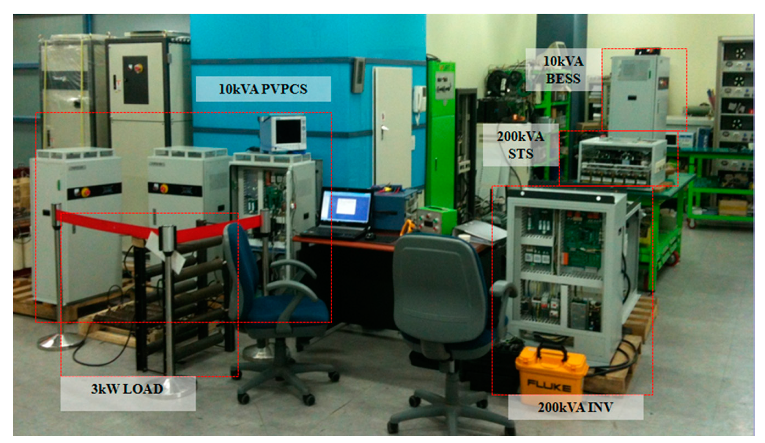
Prototypes of the components of the proposed switchgear are developed, and the test results are presented by constructing an actual testbed.
C.
An intelligent electronic device (IED) is constructed to control bidirectional power flow and to collect and process related information.
In this study, the overall structure of the proposed switchgear system and the operation of the components are described. In addition, prototypes of each component are developed and the results of building a small testbed are presented. Finally, we verify the operation of the inverter by performing an experiment on a testbed, and we show that the proposed switchgear system works normally throughout the test sequence.
This paper is organized as follows: In Section 2, we describe the overall configuration and basic control method of the bidirectional switchgear system and IED. In Section 3, we describe the testbed constructed by developing the prototype of the static transfer switch and the inverter. In Section 4, we present the test results and discuss in detail the experiment conducted on the testbed. Finally, the conclusions are given in Section 5.

2. Bidirectional Switchgear System

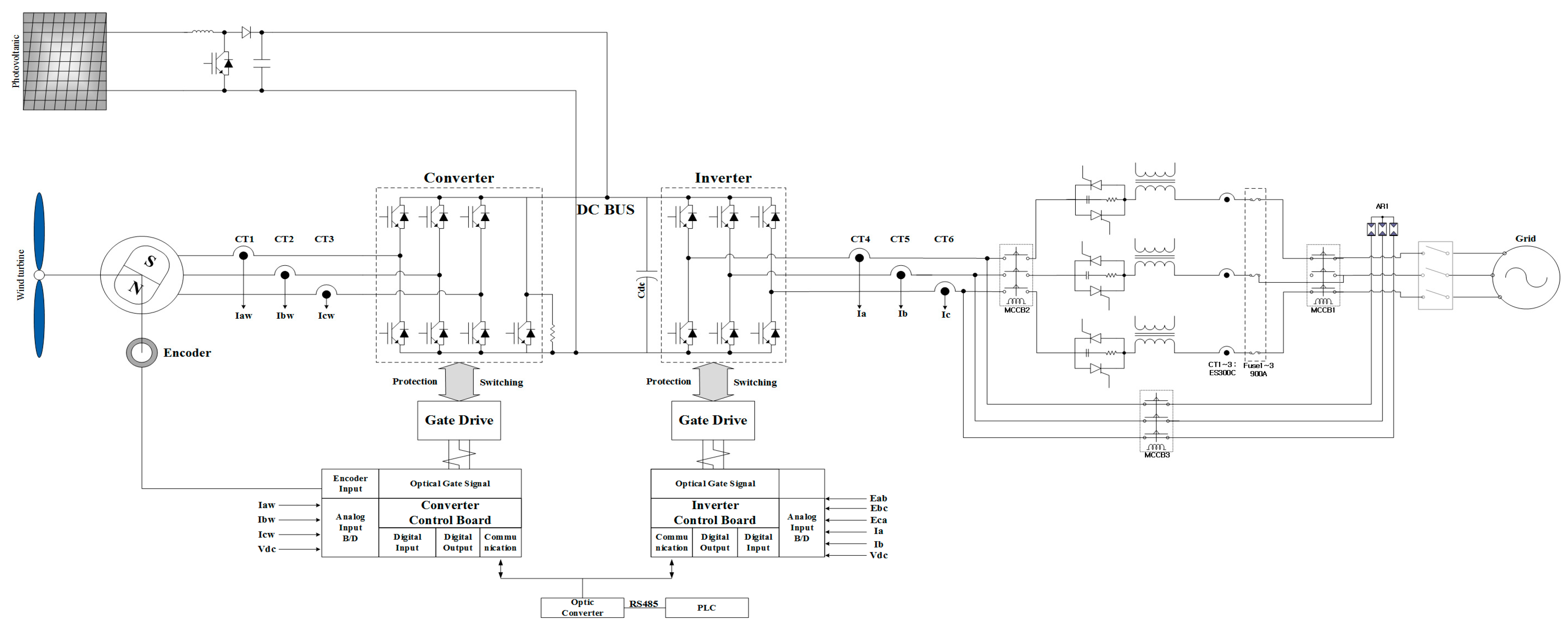
2.1. Overall System Configuration

Figure 1 illustrates the developed grid-connected system is integrated with wind turbines and photovoltaics, which is made up of a multi-input type which connects using the inverter of renewable energy equipment.
This system can reduce the number of converters; therefore, it can decrease conversion losses, but the control algorithm becomes more complicated. The system is built with a plug-in method; therefore, it can be used with distributed generations and renewable energy and its converter capacity is designed to change according to the inverter capacity [10,11].
For each distributed generation, photovoltaic equipment and fuel cells are equipped with an inverter control board. In addition, the wind turbine equipment and power generators are equipped with an inverter and converter control board, and therefore the distributed generations’ capacity can be controlled according to its output of generation.

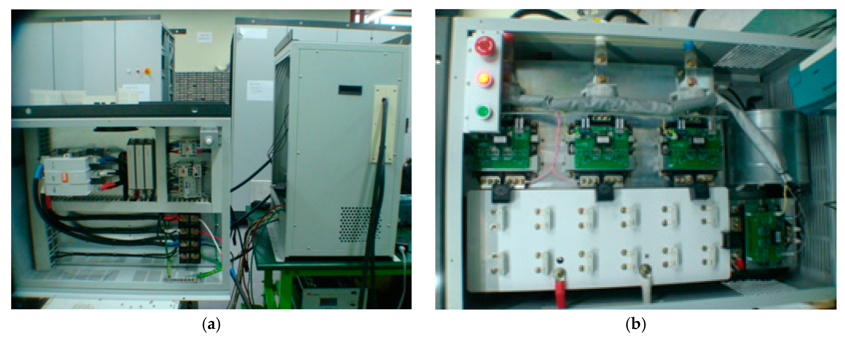
2.2. AC/DC Switchgear Panel

Figure 2 illustrates the system composition of the power carrying device (PCD) that connects the AC/DC switchgear panel with distributed generations. Power that is more than 22.9 kV is supplied from the Korea Electric Power Corporation and the supplied power is converted through a pole transformer or switchgear panel transformer, in accordance with the form of voltage preferred by consumers.
The power generated by photovoltaics and wind turbines is converted into 380 V voltage, and then transferred to consumers. The distributed generations improve the quality of energy by applying bilateral power store equipment that can supply the power to consumers after saving generated power. The PCD acts as a static switch by supplying a power distribution system and distributed generations to the lower parts, according to the IED’s control signals; it can also shut off distributed generations for system protection in the case of accidents. In addition, the PCD can perform a system shut off for protection, in the case of accidents in distributed generations, the distribution system, and incoming abnormal power [12,13].

2.3. Intelligent Electronic Device

An IED is a communication system which controls power utilities by using various sensor signals and power measurement information collected from a bilateral switchgear panel linked with distributed generations. Various distributed generations can communicate between each power equipment in order to perform bilateral power flow by linking with the switchgear panel using a plug-in method. It is also an integrated communication system for power utilities and measurement which can collect all information using various data required for digital power measurement [16,17].
A switchgear panel and distributed generation require information on power measurement in order to stabilize and control the supply of power. Such information is collected by RS-485 communication using control equipment from each power utility.
Until now, digital control power information within a switchgear panel has been collected through RS-485 serial communication due to its convenience. However, in a multi-drop network, full-duplex communication is not possible, and the number of connected lines increases as the network configuration increases. In addition, since it is controlled by a software program, software work is required for errors; therefore, it is difficult to deal with information on power in real time.
In this study, we applied a standardized CANopen communication system for single communication, in order to collect real-time information on power measurement of a switchgear panel and distributed generations. This integrated communication system applies a communication standard for power utilities with switchgear panel and distributed generations, and therefore we can conveniently collect power information required for controlling power utilities.
This integrated communication system arranges measurement information of power utilities based on CANopen communication to the main power utility and collects all the information on the power status from each power utility. Through an auto power distribution system and IEC61850 communication, it exchanges information required for linking bilateral power flow and the system. A special feature is that it consists of a communication system device that is built to collect power information stably and quickly [18,19,20].

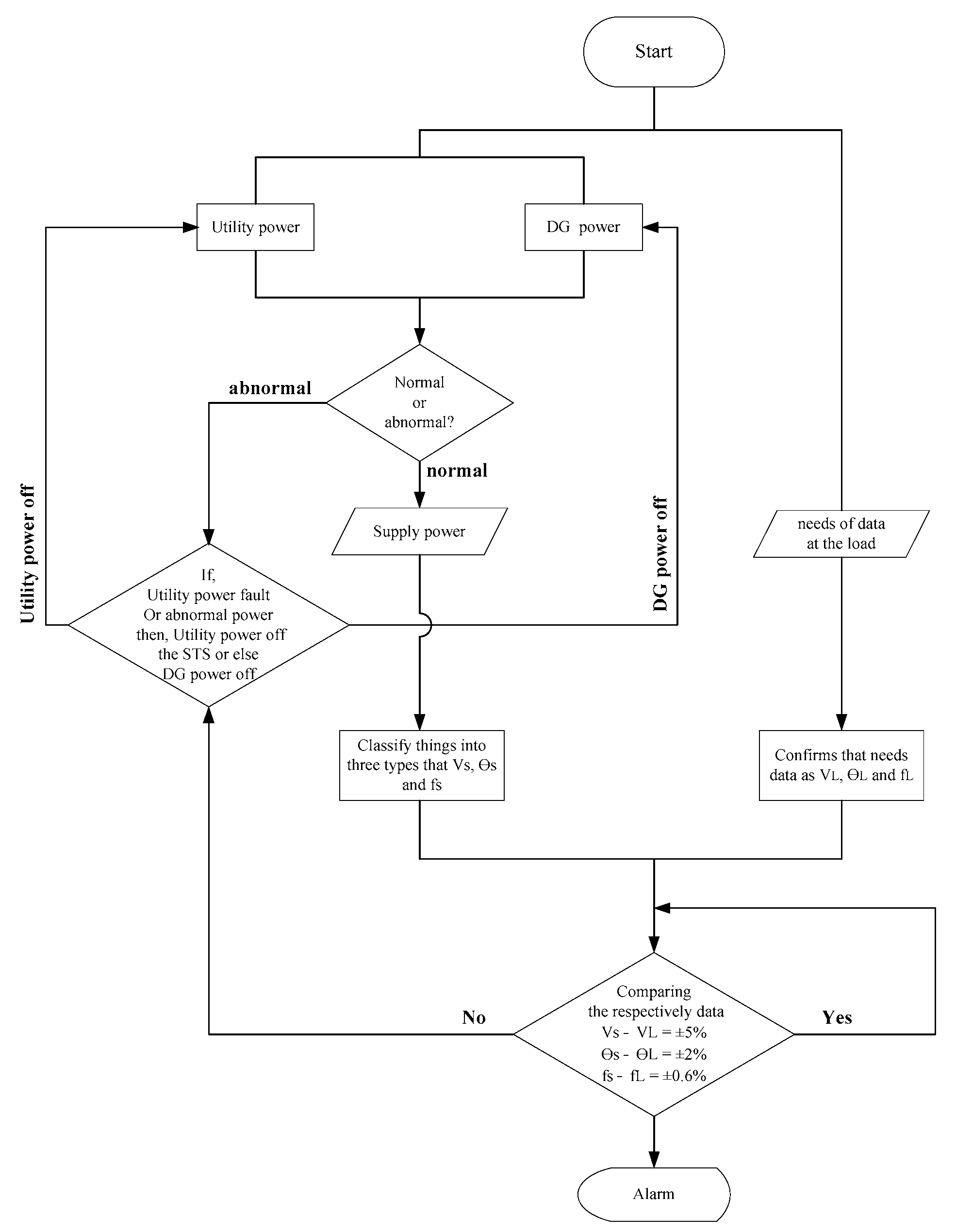
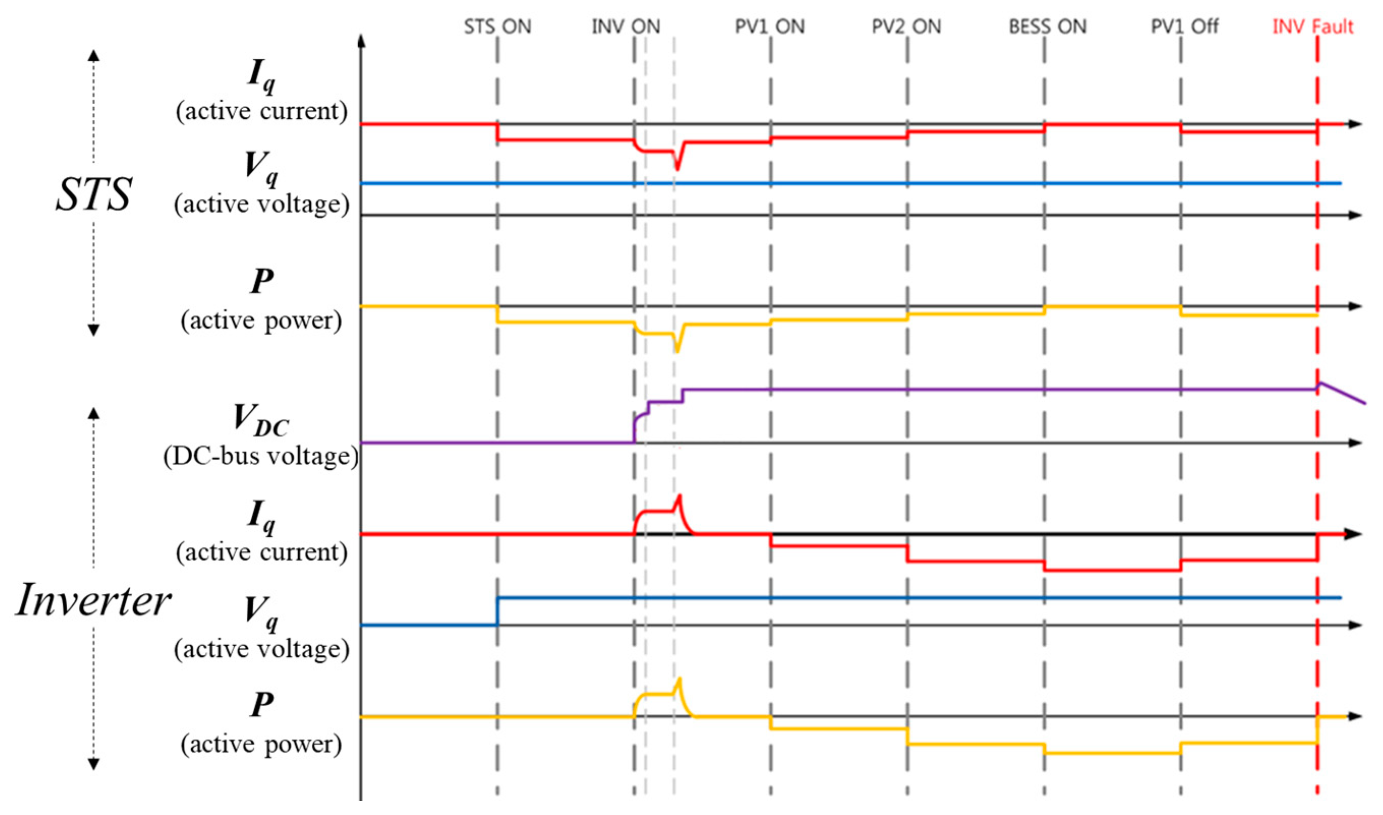
2.4. Switchgear System Control Algorithm

Figure 3 shows the algorithm for the interior of a switchgear panel’s switch control. The power supply provided to electric businesses and the distributed generations’ power linked to this power supply’s power status before it is transferred to users is categorized as voltage (V), power factor (θ), and frequency (f), and referred to as Vs, θs, and fs, respectively. Three data are identified in lower parts and they are referred to as VL, θL, and fL.
These detected data are compared to each other in the case of marginal error; therefore, it can continue to supervise without unusual events occurring. At this point, if there is more than one problem with Vs, θs, or fs, and if this problem is a signal of dysfunction and abnormal power for an electric business, then the circuit breaker which is connected to the electric business or the circuit breaker connected to the distributed generations is shut off.
In addition, first, the power of the electric business and distributed generations is compared and if there is any abnormality, the cause of abnormality is analyzed and the corresponding circuit breaker is shut off. The fluctuation rate of Vs, θs, and fs is developed so different set-ups are available in different circumstances.

3. Testbed Configuration

In this study, each prototype is developed and a testbed is built to verify the operation of the AC/DC switchgear panel. Each component is described below.

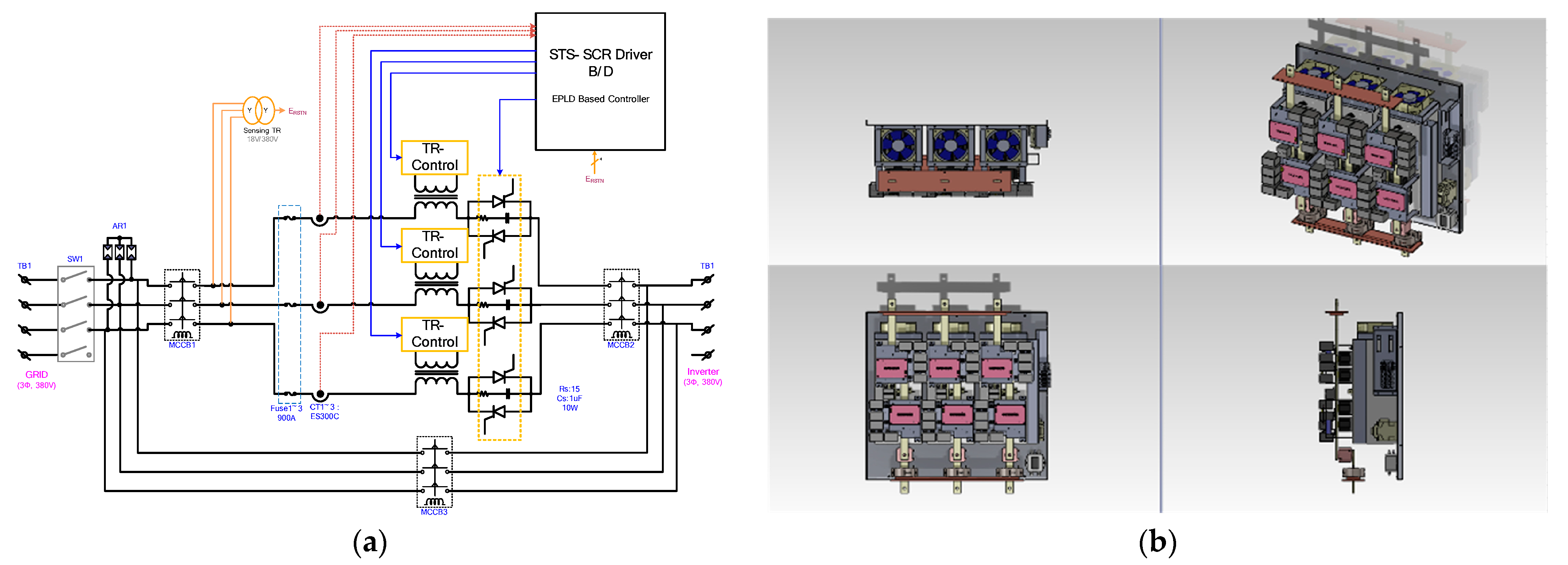
3.1. Static Transfer Switch

The conventional electromechanical transfer switches (EMTS) have been used to switch loads between two feeders. The switching operation of EMTS is slow and it needs several cycles for interruption. STS enables a large number of switching operations, no arcing during operation, and fast switching times. STS based on thyristor has a drawback regarding the total load transfer time, however it is robust and does not produce audible noise. Therefore, there is increasing interest in replacing EMTS with STS in order to accomplish fast switching. When considering bidirectional power flow, a pair of thyristor type silicon controlled rectifiers (SCRs) or triodes for alternating current (TRIACs) are commonly used in STS implementations [21,22].
In this study, the STS is a switch used to prevent system accidents by maintaining high power quality within the grid. Compared with other circuit breakers, it is fast and uses a SCR semiconductor to supply photovoltaics and wind turbine power from electric businesses to consumers, in accordance with safety ratings [7]. Figure 4 shows the configuration and diagram of the STS that was actually developed as a prototype.
Compared to a conventional automatic transfer switch (ATS) which can be mechanically converted into a solenoid device, this device is designed to control three-phase power flow at a faster rate. The composition of this system can be changed into a common power system driving mode and distributed generations’ independent driving mode in accordance with different driving situations. In addition, if there is a blackout in any system, then power can be supplied using an uninterruptible system within a one-quarter cycle using a different power system without any difficulties [21,23]. The contribution of this paper is not in the interrupting speed of STS, but in proposing a plug-in type switchgear system based on DC bus, and verifying the operation by making a prototype STS, one of its components. In operating this system, we aimed to manufacture the STS operate within at least a one-quarter cycle.

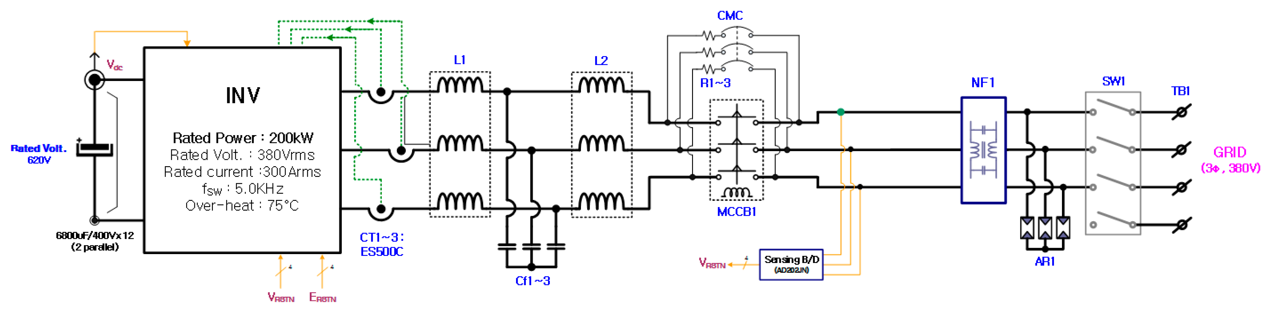
3.2. Inverter and LCL Filter in a Switchgear Panel

The power conversion system with DC/AC was developed to link the DC power produced by the DC bus commercial AC 380 V, as shown in Figure 5. The inverter is a conversion device that injects DC bus voltage into the system as a commercial AC current. The applied form is a three-phase full-bridge structure in the form of a general voltage source inverter (VSI). Each applied circuit is comprised of semiconductor element selection and passive element selection to optimally perform 200 kVA power conversion, and a digital controller to satisfy optimum conversion performance.
The inverter receives power supplies from each power conditioner system (PCS) that is connected to DC bus. Then, it is linked to the fixed frequency of the power system in order to print out the current flow. The motion state of the system inverter can be categorized into three different sections [24,25].
The filter part of the inverter was designed as an “LCL filter” due to size, weight, and economical efficiency. At this time, the resonance component of the system that can be generated by the LC does not use the general damping resistance and applies the active damping algorithm so that the resonance can be canceled. This has the advantage of reducing loss due to the use of damping resistors and not having to consider the cooling part for resistance heating. Through the simulation, when the inverter is rated at 200 kVA, the THD and power factor of the grid voltage and current are confirmed. At the rated output by the designed LCL filter, it was confirmed that the voltage and current of the system were 1.75% and 4.16%, respectively, and total THD was 5% or less. Figure 6 shows the exterior and gate drive of the inverter prototype.

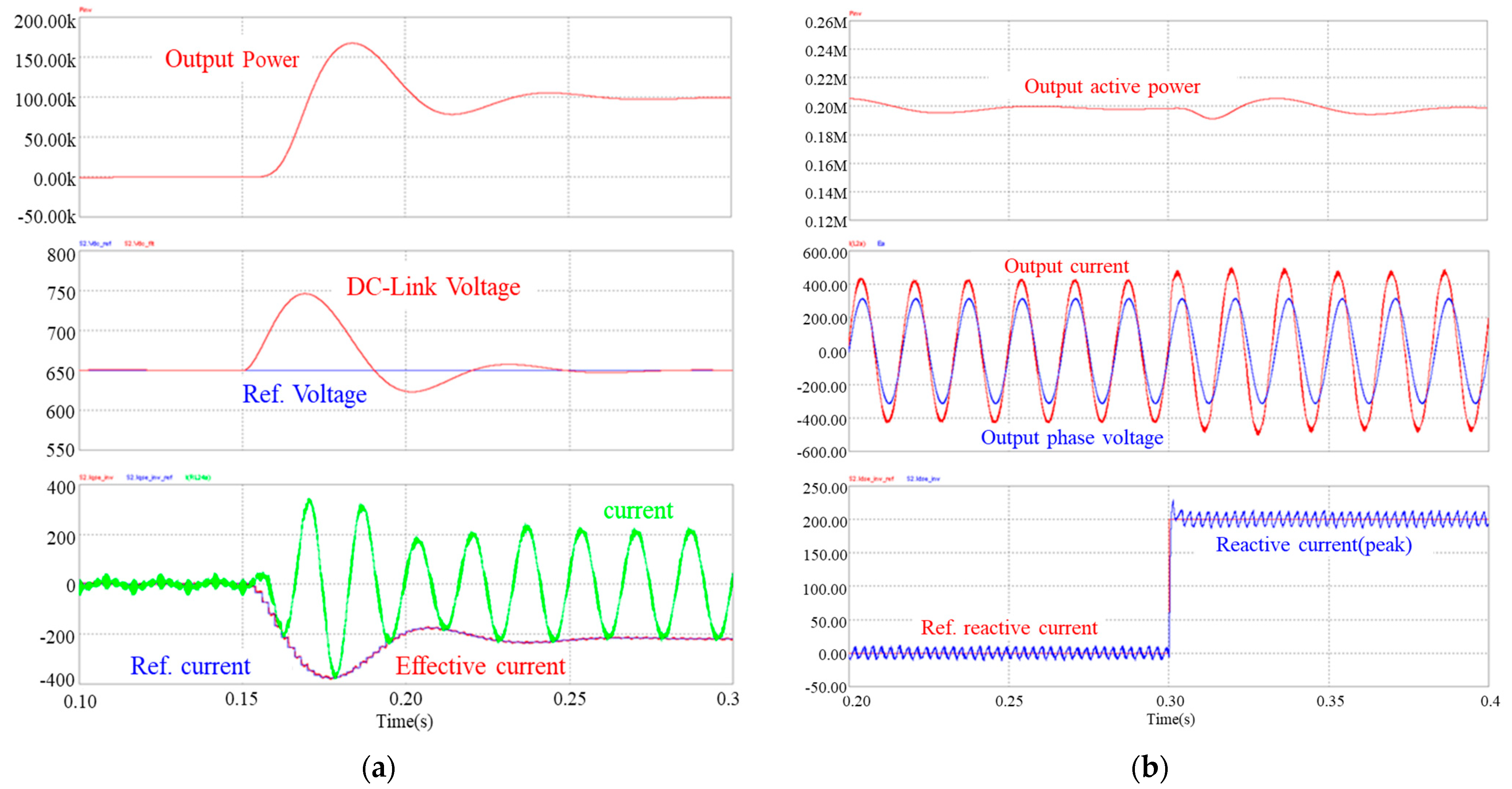
3.2.1. Normal Operation

The system inverter can be driven with a commercial power source in parallel. It can also use an islanded system and system drive which are interlocked with the power and battery management system (BMS) generated from photovoltaics based on a DC plug-in type and PCS of wind turbines. If there are any abnormalities with commercial electricity, then, the system drive is stopped and the STS automatically shuts off the system and continues with the islanded system. The input power capacity is decided by the standard of DC bus’ upper layer voltage and it is designed to perform only within normal boundaries.

3.2.2. Protective Operation

In the case of output overload or overheating, the protective operation of the system is activated under the same conditions as the automatic shut off function and short circuit.

3.2.3. Protective Operation of Generator System

Protective operation of the generator system is always driven by standard voltage. If it exceeds the drive domain, it is only able to drive within a secured domain under the limit for system protection and it is possible to command limits on outputs of each PCS. In the case of malfunction or overload of the inverter system, in order to minimize damage to the system, it is shut off using the protection function.

4. Test Result and Discussion

4.1. Test Result of Inverter Operation

Figure 7a shows the simulation result for the controller operation characteristics of the inverter when the inverter is connected to the grid, and then sudden power inflow occurs from the DC bus terminal. When approximately 100 kW of power flows from the DC-link at 0.15 sec point, about 100 kW is outputted to the system by the voltage and current controller, and the characteristics of the voltage and current controller at that time are also shown.
Inverters connected to the grid should basically be operated with a power factor value close to 1, and the power factor control should be possible within the range where capacity is possible. Figure 7b shows that the inverter injects reactive current (approximately 200A at peak) at the 0.3 s point during output operation of about 200 kW. From Figure 7b, the reactive current follows the reference value by the current controller, and the phase angle difference between the voltage and current of the system occurs.

4.2. Test Result of the Switchgear Panel

Figure 8 shows the overall configuration of the manufactured testbed for conducting the experiment. Photovoltaic PCS (PVPCS) input was used by rectifying the AC instead of the solar module and a 3 kW load was connected between the inverter and the STS. The voltage of the DC bus was 700 V and the AC system was composed of three-phase 380 V.
The grid-connected operation test was performed when the inverter detected a fault and the inverter stopped operation faster than the IED command. Figure 9 shows the sequence of the actual experiment. First, the STS starts operation, and then, if there is no problem, the inverter starts operation. Then, the PVPCS and battery ESS (BESS) start to operate. As a fault condition, it is assumed that, first, one PVPCS stops operation, and then a fault occurs in the inverter.
Figure 10 shows the experimental results according to the test sequence shown in Figure 9. When the PVPCS starts to operate after the STS and the inverter are operated, sequentially, it can be seen that the inverter generates more output. When the PVPCS stops, the output decreases accordingly. At this time, when a fault occurs in the inverter, the output of the inverter becomes zero and the voltage of the DC bus increases. Each PCS detects the increased voltage and stops operation. If the DC bus voltage has a value of 800 V or more, normal operation is possible by limiting it to not exceed 800 V through the control of the inverter, as shown in Figure 10.

5. Conclusions

In this study, we develop a plug-in type of switchgear system for controlling bidirectional power flow. Because the topology inside the switchgear is a plug-in type with DC bus, it enables the control of power flow by connecting the converters of various distributed generations to the inverter. The proposed switchgear system consists of an interconnected inverter, an STS that controls bidirectional power flow, and an IED based on CANopen. For the inverter in the switchgear system, the existing distributed generations can be connected to the system directly or use it only in accordance with consumer capacity. That is why, after development, the converters of the distributed generation can be connected separately to the inverter. In case there are abnormalities in the AC system, it is separated from the consumer, and the consumer can receive power supply from distributed generation through the switchgear system as an islanded system. The STS is responsible for the connecting function within the switchgear. If there is any abnormality in the system, it blocks the system from consumer parts within a one-quarter cycle. In this study, prototypes of the inverter and STS are developed and a testbed is built to verify the operation of the AC/DC switchgear panel. In addition, we verify the operation of the inverter and the switchgear system through an experiment on a testbed according to a test sequence. The proposed plug-in type of switchgear system including the DC bus is expected to provide a useful business model for the provider of distributed generation in response to an increase in the penetration of distributed generation and by enabling effective control.

Author Contributions

K.-W.P. conceived the idea and did preliminary work. C.-H.K. provided guidelines necessary to complete the work. C.-H.K. analyzed the results, reviewed the paper, and directed significant improvements. K.-W.P. wrote the paper. All authors have read and agreed to the published version of the manuscript.

Funding

This research received no external funding.

Institutional Review Board Statement

Not applicable.

Informed Consent Statement

Not applicable.

Data Availability Statement

Not applicable.

Conflicts of Interest

The authors declare no conflict of interest.

References

  1. Kim, J.H.; Kim, S.H.; Kim, J.H. Pressure Retarded Osmosis Process: Current Status and Future. J. Korean Soc. Environ. Eng. 2014, 36, 791–802. [Google Scholar]
  2. Kang, B.S.; Kim, J.C.; Moon, J.F.; Park, G.J.; Kweon, Y.B. Realization of the Information Visualization of Electric Power Monitoring System for MV/LV Distribution Customers. J. Korean Inst. Illum. Electr. Install. Eng. 2004, 18, 157–166. [Google Scholar]
  3. Jaekel, B.W. General Description and Assessment Concept for Magnetic Field Distribution Caused by Switchgear In-stallations. IEEE Trans. Power Deliv. 2007, 22, 167–177. [Google Scholar] [CrossRef]
  4. Treanton, B.; Palomo, J.; Kroposki, B.; Thomas, H. Advanced Power Electrics Interfaces for Distributed Energy Workshop Summary; NREL/BK-581-40480; National Renewable Energy Lab. (NREL): Golden, CO, USA, 2006. [Google Scholar] [CrossRef] [Green Version]
  5. Mettam, J. Insulation aging in 12kV switchger-a users perspective. In Proceeding of the 4th International Conference on Properties and Applications of Dielectric Materials, Brisbane, QLD, Australia, 3–8 July 1994; pp. 772–775. [Google Scholar]
  6. Okamoto, T.; Shibuya, M.; Takahashi, T.; Mizutani, Y.; Takahashi, T.; Takeda, T. Development of all solid substations. In Proceedings of the National Convention Record IEE Japan, Tokyo, Japan, 26 March 2002; p. 133. [Google Scholar]
  7. Shioiri, T.; Sao, J.; Ozaki, T.; Sakaguchi, O.; Kamikawaji, T.; Mjyagawa, M.; Homma, M.; Suzuki, K. Insulation technology for medium voltage solid insulated switchgear. In Proceedings of the Anual Report Conference on Electrical Insulation and Dielectric Phenomena, Albuquerque, NM, USA, 19–22 October 2003. [Google Scholar]
  8. Rodriguez-Diaz, E.; Vasquez, J.C.; Guerrero, J.M. Potential energy savings by using direct current for residential applications: A Danish household study case. In Proceedings of the 2017 IEEE Second International Conference on DC Microgrids, Nuremburg, Germany, 27–29 June 2017; pp. 547–552. [Google Scholar]
  9. Kong, X.; Yan, Z.; Guo, R.; Xu, X.; Fang, C. Three-Stage Distributed State Estimation for AC-DC Hybrid Distribution Network Under Mixed Measurement Environment. IEEE Access 2018, 6, 39027–39036. [Google Scholar] [CrossRef]
  10. Chakraborty, S.; Pink, C.; Kroposki, J.P.B.; Kem, G. Development of Standardized Power Electric Components, Sub-Systems and Systems for Increased Modularity and Scalability; NREL Technical Report; NREL: Golden, CO, USA, 2007. [Google Scholar]
  11. Lai, J.S. Power Conditioning Systems for Renewable Energies. In Proceedings of the International Conference on Electrical Machines and Systems, Seoul, Korea, 8–11 October 2007. [Google Scholar]
  12. Gerber, D.L.; Vossos, V.; Feng, W.; Khandekar, A.; Marnay, C.; Nordman, B. A simulation based comparison of AC and DC power distribution networks in buildings. Appl. Energy 2018, 210, 1167–1187. [Google Scholar] [CrossRef] [Green Version]
  13. Song, I.; Jung, W.; Kim, J.; Yun, S.; Choi, J.; Ahn, S. Operation Schemes of Smart Distribution Networks with Distributed Energy Resources for Loss Reduction and Service Restoration. IEEE Trans. Smart Grid 2013, 4, 367–374. [Google Scholar] [CrossRef]
  14. Park, C.W. Simulation of DC Microgrid with PV Generation. J. KIEE P 2017, 66, 267–273. [Google Scholar]
  15. Kroposki, B.; Lasseter, R.; Ise, T.; Morozumi, S.; Papathanassiou, S.; Hatziargyriou, N. Making microgrids work. IEEE Power Energy Mag. 2008, 6, 40–53. [Google Scholar] [CrossRef]
  16. Silos, Á.; Señís, A.; de Pozuelo, R.M.; Zaballos, A. Using IEC 61850 GOOSE Service for Adaptive ANSI 67/67N Protection in Ring Main Systems with Distributed Energy Resources. Energies 2017, 10, 1685. [Google Scholar] [CrossRef] [Green Version]
  17. Yi, Y.H.; Zhang, J.J.; Liu, B.; Xu, L.Z.; Cao, Y.J.; Guo, C.X. A new-style centralized IED based on IEC 61850. In Proceedings of the IEEE Power and Energy Society General Meeting—Conversion and Delivery of Electrical Energy in the 21st Century, Pittsburgh, PA, USA, 20–24 July 2008; pp. 1–5. [Google Scholar]
  18. Deng, W.; Pei, W.; Shen, Z.; Zhao, Z.; Qu, H. Adaptive Micro-Grid Operation Based on IEC 61850. Energies 2015, 8, 4455–4475. [Google Scholar] [CrossRef] [Green Version]
  19. Ingram, D.M.E.; Schaub, P.; Taylor, R.R.; Campbell, D.A. Performance Analysis of IEC 61850 Sampled value Process Bus Networks. IEEE Trans. Ind. Inform. 2013, 9, 1445–1454. [Google Scholar] [CrossRef]
  20. IEC Standard for Specific Communication Service Mapping (SCSM)—Mappings to MMS (ISO/IEC 9506-1 and ISO/IEC 9506-2) and to ISO/IEC 8802-3, 2nd ed.; IEC TC-57, IEC 61850-8-1; IEC: Geneva, Switzerland, 2011.
  21. Mokhtari, H.; Dewan, S.B.; Travani, M.R. Performance evaluation of thyristor based static transfer switch. IEEE Trans. Power Deliv. 2000, 15, 960–966. [Google Scholar] [CrossRef]
  22. Rodrigues, M.V.M.; da Silva, N.; Gonçalves, F.A.S. Static Transfer Switch Applied to Single-Phase Uninterruptible Power Supply. In Proceedings of the 2019 IEEE 15th Brazilian Power Electronics Conference and 5th IEEE Southern Power Electronics Conference (COBEP/SPEC), Santos, Brazil, 1–4 December 2019; pp. 1–6. [Google Scholar]
  23. Mokhtaru, H.; Travani, M.R. Effect of source phase difference on static transfer switch performance. IEEE Trans. Power Deliv. 2007, 22, 1125–1131. [Google Scholar] [CrossRef]
  24. Liu, F.; Xu, P.; Chen, G. Study on three-phase photovoltaic gridconnected control system with LCL filter. Acta Energae Sol. Sin. 2008, 29, 965–970. [Google Scholar]
  25. Teng, G.; Xiao, G.; Zhang, Z.; Qi, Y.; Lu, Y. A Single-loop Current Control Method for LCL-filtered Grid-connected Inverters Based on the Repetitive Controller. Proc. CSEE 2013, 33, 13–21. [Google Scholar]
Figure 1. Power conversion system using singular inverter connected photovoltaic and wind turbine generation.
Energies 14 03187 g001
Figure 2. System composition of the AC/DC switchgear panel.
Energies 14 03187 g002
Figure 3. Switchgear panel’s control algorithm.
Energies 14 03187 g003
Figure 4. (a) Diagram of the static transfer switch; (b) the internal configuration of the static transfer switch.
Energies 14 03187 g004
Figure 5. Block diagram of 200 kW inverter.
Energies 14 03187 g005
Figure 6. Prototype of a 200-kW inverter. (a) Exterior of inverter; (b) gate driver.
Energies 14 03187 g006
Figure 7. (a) DC-link controller power at 650 V after variable power and (b) power factor control.
Energies 14 03187 g007
Figure 8. Testbed configuration.
Energies 14 03187 g008
Figure 9. Test sequence.
Energies 14 03187 g009
Figure 10. Test results according to the test sequence.
Energies 14 03187 g010
Publisher’s Note: MDPI stays neutral with regard to jurisdictional claims in published maps and institutional affiliations.

