
Towards the Hydrogen Economy—A Review of the Parameters That Influence the Efficiency of Alkaline Water Electrolyzers


Abstract
:1. Introduction
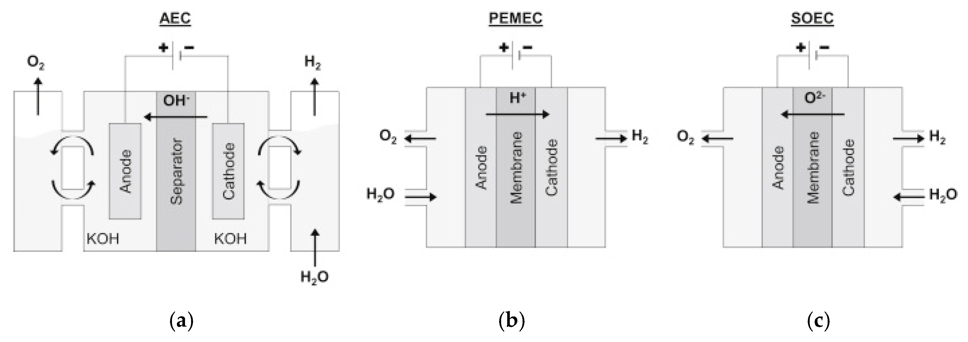
2. Water Electrolysis
3. Thermodynamics
3.1. Ohmic Overpotential
3.2. Activation Overpotential
3.3. Concentration Overpotential
4. Efficiency-Related Parameters
4.1. Electrocatalysts
4.1.1. HER Mechanism
4.1.2. HER Electrocatalysts
4.1.3. OER Mechanism
4.1.4. OER Electrocatalysts
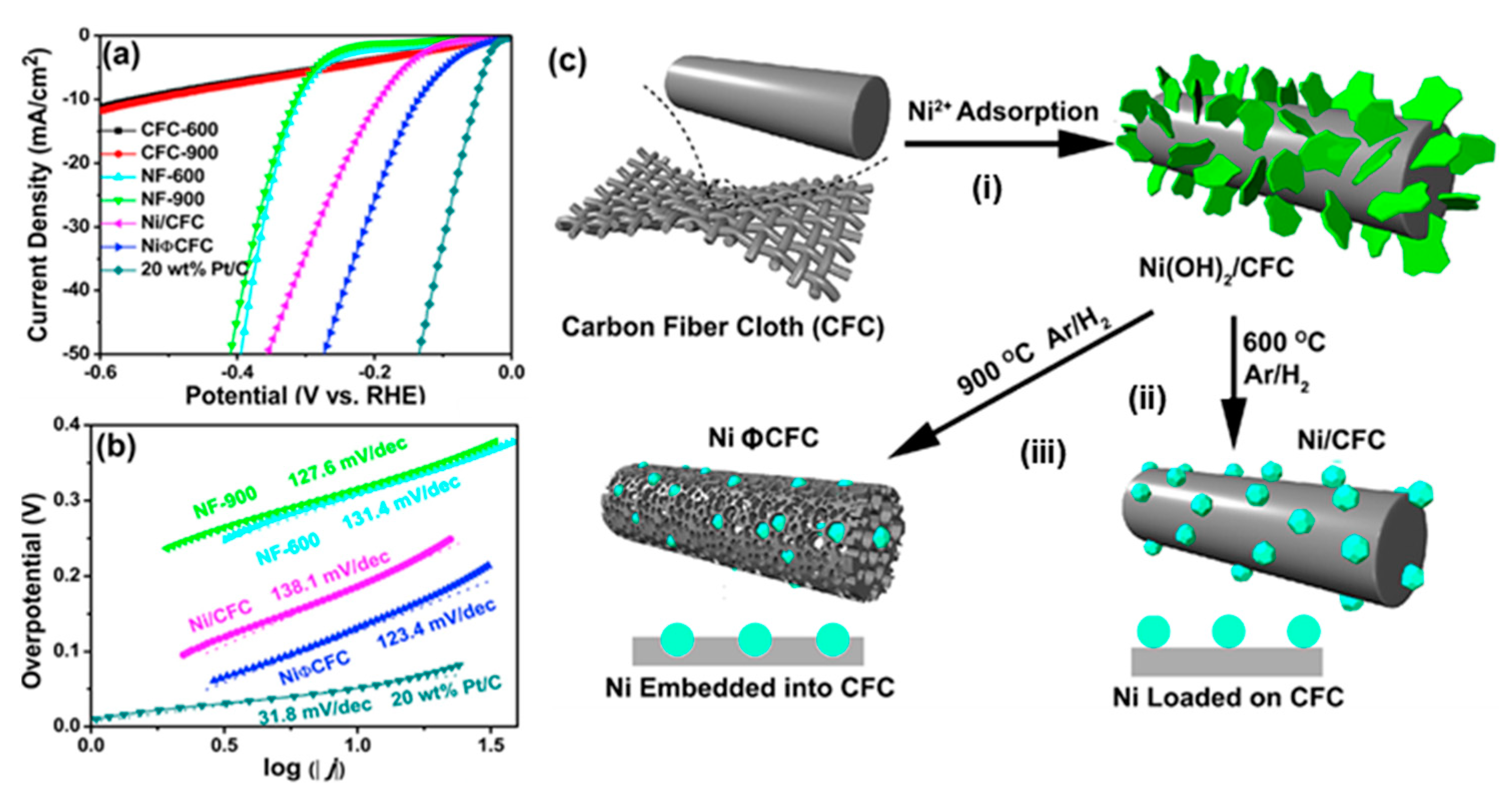
4.1.5. Preparation Methods
4.2. Electrolyte Concentration
Electrolyte Additives
4.3. Separator Material
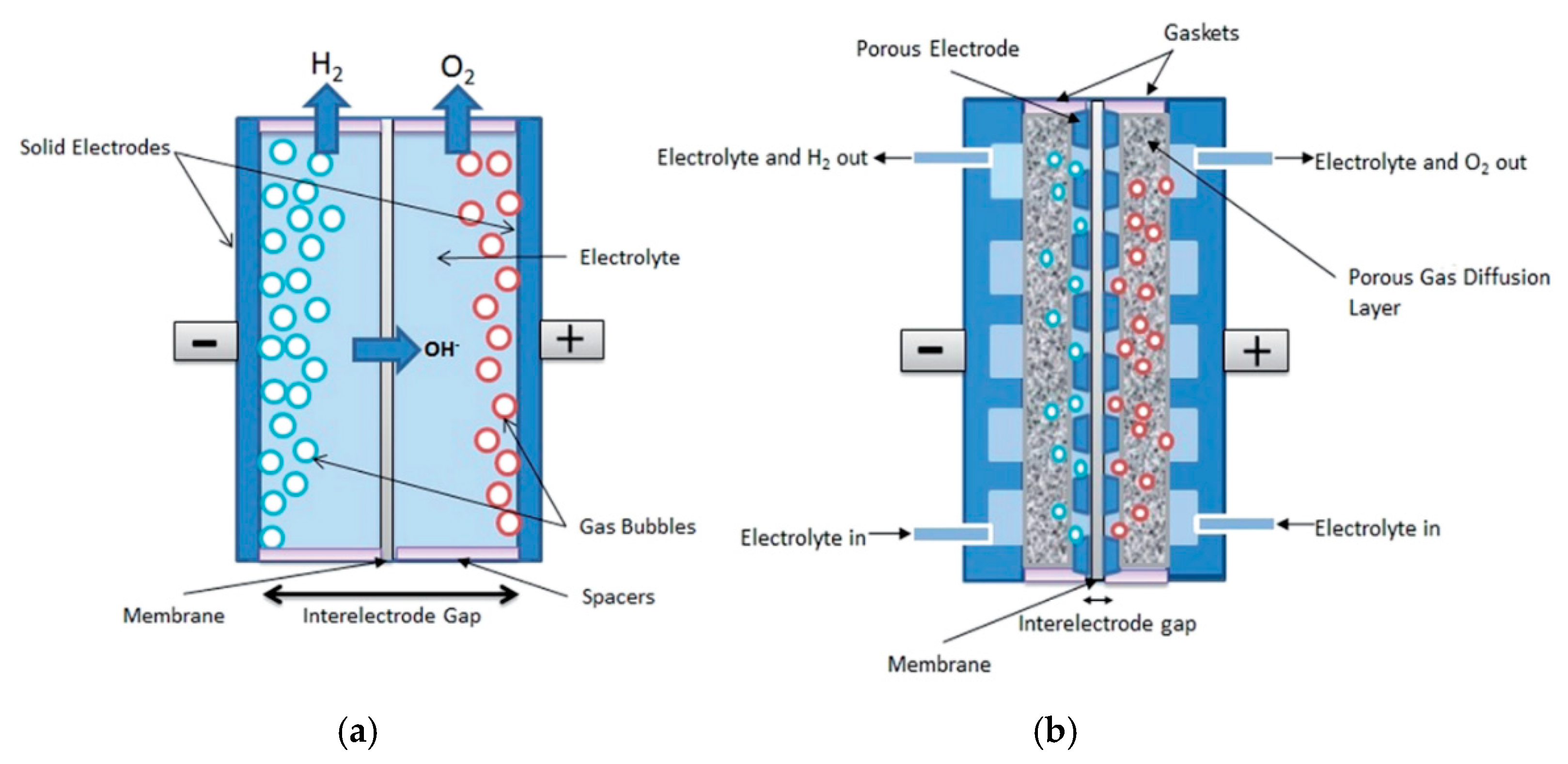
4.4. Interelectrode Distance
4.5. High Temperature and Pressure Electrolysis
5. Economic Aspects
6. Conclusions
Author Contributions
Funding
Institutional Review Board Statement
Informed Consent Statement
Data Availability Statement
Acknowledgments
Conflicts of Interest
References
- Veziroğlu, T.N. Century’s Energy: Hydrogen Energy System. In Proceedings of the 13th International Conference on Emerging Nuclear Energy Systems, Istanbul, Turkey, 3–8 June 2007; pp. 1–16. Available online: http://www.jicable.org/wets03/pdf/wets03-1-10.pdf (accessed on 2 May 2020).
- BP. BP Statistical Review of World Energy June 2016. Available online: http://oilproduction.net/files/especial-BP/bp-statistical-review-of-world-energy-2016-full-report.pdf (accessed on 10 June 2020).
- David, M.; Ocampo-Martínez, C.; Sánchez-Peña, R. Advances in alkaline water electrolyzers: A review. J. Energy Storage 2019, 23, 392–403. [Google Scholar] [CrossRef] [Green Version]
- Abe, J.O.; Popoola, A.P.I.; Ajenifuja, E.; Popoola, O.M. Hydrogen energy, economy and storage: Review and recommendation. Int. J. Hydrogen Energy 2019, 44, 15072–15086. [Google Scholar] [CrossRef]
- Baykara, S.Z. Hydrogen: A brief overview on its sources, production and environmental impact. Int. J. Hydrogen Energy 2018, 43, 10605–10614. [Google Scholar] [CrossRef]
- IRENA. Hydrogen from Renewable Power: Technology Outlook for the Energy Transition; International Renewable Energy Agency: Abu Dhabi, United Arab Emirates, 2018; Available online: https://www.irena.org/publications/2018/Sep/Hydrogen-from-renewable-power (accessed on 10 June 2020).
- Santos, D.M.F.; Sequeira, C.A.C.; Figueiredo, J.L. Hydrogen Production by Alkaline Water Electrolysis. Quim. Nova 2013, 36, 1176–1193. [Google Scholar] [CrossRef]
- Zeng, K.; Zhang, D. Recent progress in alkaline water electrolysis for hydrogen production and applications. Prog. Energy Combust. Sci. 2010, 36, 307–326. [Google Scholar] [CrossRef]
- Schmidt, O.; Gambhir, A.; Staffell, I.; Hawkes, A.; Nelson, J.; Few, S. Future cost and performance of water electrolysis: An expert elicitation study. Int. J. Hydrogen Energy 2017, 42, 30470–30492. [Google Scholar] [CrossRef]
- Rashid, M.M.; Al Mesfer, M.K.; Naseem, H.; Danish, M. Hydrogen Production by Water Electrolysis: A Review of Alkaline Water Electrolysis, PEM Water Electrolysis and High Temperature Water Electrolysis. Int. J. Eng. Adv. Technol. 2015, 4, 2249–8958. Available online: https://citeseerx.ist.psu.edu/viewdoc/download?doi=10.1.1.673.5912&rep=rep1&type=pdf (accessed on 2 May 2020).
- Barbir, F. PEM electrolysis for production of hydrogen from renewable energy sources. Sol. Energy 2005, 78, 661–669. [Google Scholar] [CrossRef]
- Li, D.; Motz, A.R.; Bae, C.; Fujimoto, C.; Yang, G.; Zhang, F.; Ayers, K.E.; Kim, Y.S. Durability of anion exchange membrane water electrolyzers. Energy Environ. Sci. 2021. [Google Scholar] [CrossRef]
- Laguna-Bercero, M.A. Recent advances in high temperature electrolysis using solid oxide fuel cells: A review. J. Power Sources 2012, 203, 4–16. [Google Scholar] [CrossRef] [Green Version]
- U.S. Bureau of Laber Statistics. Producer Price Indexes. Available online: https://www.bls.gov/ppi/#data (accessed on 5 November 2020).
- Kjartansdóttir, C.K.; Moller, P. Development of Hydrogen Electrodes for Alkaline Water Electrolysis. Doctoral Thesis, Technical University of Denmark, Lyngby, Denmark, 2014. [Google Scholar]
- Feng, Q.; Yuan, X.Z.; Liu, G.; Wei, B.; Zhang, Z.; Li, H.; Wang, H. A review of proton exchange membrane water electrolysis on degradation mechanisms and mitigation strategies. J. Power Sources 2017, 366, 33–55. [Google Scholar] [CrossRef]
- Schalenbach, M.; Tjarks, G.; Carmo, M.; Lueke, W.; Mueller, M.; Stolten, D. Acidic or Alkaline? Towards a New Perspective on the Efficiency of Water Electrolysis. J. Electrochem. Soc. 2016, 163, 3197–3208. [Google Scholar] [CrossRef] [Green Version]
- Felgenhauer, M.; Hamacher, T. State-of-the-art of commercial electrolyzers and on-site hydrogen generation for logistic vehicles in South Carolina. Int. J. Hydrogen Energy 2015, 40, 2084–2090. [Google Scholar] [CrossRef]
- Pletcher, D.; Li, X. Prospects for alkaline zero gap water electrolysers for hydrogen production. Int. J. Hydrogen Energy 2011, 36, 15089–15104. [Google Scholar] [CrossRef] [Green Version]
- Flowers, P.; Theopold, K.; Langley, R. Chemistry—LibreTexts, 16.7 Electrolysis. Available online: https://chem.libretexts.org/Bookshelves/General_Chemistry/Map%3A_Chemistry_-_Atoms_First_(OpenSTAX)/16%3A_Electrochemistry/16.7%3A_Electrolysis (accessed on 30 May 2020).
- Wang, W.; Wei, X.; Choi, D.; Lu, X.; Yang, G.; Sun, C. Chapter 1—Electrochemical cells for medium-and large-scale energy storage: Fundamentals. In Advances in Batteries for Medium and Large-Scale Energy Storage, 1st ed.; Menictas, C., Skyllas-Kazacos, M., Lim, T.M., Eds.; Woodhead Publishing Series in Energy: Cambridge, UK, 2014; pp. 3–28. [Google Scholar] [CrossRef]
- Zouhri, K.; Lee, S.Y. Evaluation and optimization of the alkaline water electrolysis ohmic polarization: Exergy study. Int. J. Hydrogen Energy 2016, 41, 7253–7263. [Google Scholar] [CrossRef]
- Carmo, M.; Stolten, D. Energy storage using hydrogen produced from excess renewable electricity: Power to hydrogen. In Science and Engineering of Hydrogen-Based Energy Technologies. Hydrogen Production and Practical Applications in Energy Generation, 1st ed.; Miranda, P.E., Ed.; Academic Press: Cambridge, MA, USA, 2018; pp. 165–199. [Google Scholar] [CrossRef]
- Wang, M.; Wang, Z.; Gong, X.; Guo, Z. The intensification technologies to water electrolysis for hydrogen production—A review. Renew. Sustain. Energy Rev. 2014, 29, 573–588. [Google Scholar] [CrossRef]
- Zinola, C.F.; Martins, M.E.; Tejera, E.P.; Neves, N.P. Electrocatalysis: Fundamentals and Applications. Int. J. Electrochem. 2012, 2012, 874687. [Google Scholar] [CrossRef] [Green Version]
- Tahir, M.; Pan, L.; Idrees, F.; Zhang, X.; Wang, L.; Zou, J.J.; Wang, Z.L. Electrocatalytic oxygen evolution reaction for energy conversion and storage: A comprehensive review. Nano Energy 2017, 37, 136–157. [Google Scholar] [CrossRef]
- Gong, M.; Wang, D.Y.; Chen, C.C.; Hwang, B.J.; Dai, H. A mini review on nickel-based electrocatalysts for alkaline hydrogen evolution reaction. Nano Res. 2016, 9, 28–46. [Google Scholar] [CrossRef]
- Jović, V.D.; Jović, B.M.; Lačnjevac, U.; Krstajić, N.V.; Zabinski, P.; Elezović, N.R. Accelerated service life test of electrodeposited NiSn alloys as bifunctional catalysts for alkaline water electrolysis under industrial operating conditions. J. Electroanal. Chem. 2018, 819, 16–25. [Google Scholar] [CrossRef]
- Chen, Z.; Duan, X.; Wei, W.; Wang, S.; Ni, B.J. Recent advances in transition metal-based electrocatalysts for alkaline hydrogen evolution. J. Mater. Chem. A 2019, 7, 14971–15005. [Google Scholar] [CrossRef]
- Vij, V.; Sultan, S.; Harzandi, A.M.; Meena, A.; Tiwari, J.N.; Lee, W.G.; Yoon, T.; Kim, K.S. Nickel-based electrocatalysts for energy-related applications: Oxygen reduction, oxygen evolution, and hydrogen evolution reactions. ACS Catal. 2017, 7, 7196–7225. [Google Scholar] [CrossRef]
- Mohammed-Ibrahim, J.; Xiaoming, S. Recent progress on earth abundant electrocatalysts for hydrogen evolution reaction (HER) in alkaline medium to achieve efficient water splitting—A review. J. Energy Chem. 2019, 34, 111–160. [Google Scholar] [CrossRef]
- Chen, Y.; Rui, K.; Zhu, J.; Dou, S.X.; Sun, W. Recent Progress on Nickel-Based Oxide/(Oxy)Hydroxide Electrocatalysts for the Oxygen Evolution Reaction. Chem. Eur. J. 2019, 25, 703–713. [Google Scholar] [CrossRef] [PubMed]
- Roy, A.; Watson, S.; Infield, D. Comparison of electrical energy efficiency of atmospheric and high-pressure electrolysers. Int. J. Hydrogen Energy 2016, 31, 1964–1979. [Google Scholar] [CrossRef]
- Coli, A.N.; Girault, H.H.; Battistel, A. Non-precious electrodes for practical alkaline water electrolysis. Materials 2019, 12, 1336. [Google Scholar] [CrossRef] [PubMed] [Green Version]
- Zhou, Y.; Lin, T.; Luo, X.; Yan, Z.; Wu, J.; Wang, J.; Shen, Y. Mechanistic study on nickel-molybdenum based electrocatalysts for the hydrogen evolution reaction. J. Catal. 2020, 388, 122–129. [Google Scholar] [CrossRef]
- Hu, X.; Tian, X.; Lin, Y.W.; Wang, Z. Nickel foam and stainless steel mesh as electrocatalysts for hydrogen evolution reaction, oxygen evolution reaction and overall water splitting in alkaline media. RSC Adv. 2019, 9, 31563–31571. [Google Scholar] [CrossRef] [Green Version]
- Wang, L.; Li, Y.; Xia, M.; Li, Z.; Chen, Z.; Ma, Z.; Qin, X.; Shao, G. Ni nanoparticles supported on graphene layers: An excellent 3D electrode for hydrogen evolution reaction in alkaline solution. J. Power Sources 2017, 347, 220–228. [Google Scholar] [CrossRef]
- Jović, V.D.; Jović, B.M.; Elezović, N.R.; Gajić-Krstajić, L. Corrected accelerated service life test of electrodeposited NiSn alloys and Ni as cathodes for industrial alkaline water electrolysis. J. Serb. Chem. Soc. 2019, 84, 1271–1286. [Google Scholar] [CrossRef] [Green Version]
- Li, J.; Wei, G.; Zhu, Y.; Xi, Y.; Pan, X.; Ji, Y.; Zatovsky, I.V.; Han, W. Hierarchical NiCoP nanocone arrays supported on Ni foam as an efficient and stable bifunctional electrocatalyst for overall water splitting. J. Mater. Chem. A 2017, 5, 14828–14837. [Google Scholar] [CrossRef]
- Chen, L.; Song, Y.; Liu, Y.; Xu, L.; Qin, J.; Lei, Y.; Tang, Y. NiCoP nanoleaves array for electrocatalytic alkaline H2 evolution and overall water splitting. J. Energy Chem. 2020, 50, 395–401. [Google Scholar] [CrossRef]
- Xing, Z.; Li, Q.; Wang, D.; Yang, X.; Sun, X. Self-supported nickel nitride as an efficient high-performance three-dimensional cathode for the alkaline hydrogen evolution reaction. Electrochim. Acta 2016, 191, 841–845. [Google Scholar] [CrossRef]
- Zhang, B.; Xiao, C.; Xie, S.; Liang, J.; Chen, X.; Tang, Y. Iron-nickel nitride nanostructures in situ grown on surface-redox-etching nickel foam: Efficient and ultrasustainable electrocatalysts for overall water splitting. Chem. Mater. 2016, 28, 6934–6941. [Google Scholar] [CrossRef]
- Yang, L.; Zhou, W.; Jia, J.; Xiong, T.; Zhou, K.; Feng, C.; Zhou, J.; Tang, Z.; Chen, S. Nickel nanoparticles partially embedded into carbon fiber cloth via metal-mediated pitting process as flexible and efficient electrodes for hydrogen evolution reactions. Carbon 2017, 122, 710–717. [Google Scholar] [CrossRef]
- Wang, L.; Li, Y.; Yin, X.; Wang, Y.; Lu, L.; Song, A.; Xia, M.; Li, Z.; Qin, X.; Shao, G. Comparison of three nickel-based carbon composite catalysts for hydrogen evolution reaction in alkaline solution. Int. J. Hydrogen Energy 2017, 42, 22655–22662. [Google Scholar] [CrossRef]
- Raj, I.A.; Vasu, K.I. Transition metal-based hydrogen electrodes in alkaline solution—Electrocatalysis on nickel based binary alloy coatings. J. Appl. Electrochem. 1990, 20, 32–38. [Google Scholar] [CrossRef]
- Raj, I.A.; Vasu, K.I. Transition metal-based cathodes for hydrogen evolution in alkaline solution: Electrocatalysis on nickel-based ternary electrolytic codeposits. J. Appl. Electrochem. 1992, 22, 471–477. [Google Scholar] [CrossRef]
- Kim, J.E.; Bae, K.K.; Park, C.S.; Jeong, S.U.; Baik, K.H.; Kim, J.W.; Kang, K.S.; Lee, K.B.; Kim, Y.H. Electrochemical characterization of Raney nickel electrodes prepared by atmospheric plasma spraying for alkaline water electrolysis. J. Ind. Eng. Chem. 2019, 70, 160–168. [Google Scholar] [CrossRef]
- Han, Q.; Liu, K.; Chen, J.; Wei, X. Hydrogen evolution reaction on amorphous Ni-S-Co alloy in alkaline medium. Int. J. Hydrogen Energy 2003, 28, 1345–1352. [Google Scholar] [CrossRef]
- Wang, Y.; Kong, B.; Zhao, D.; Wang, H.; Selomulya, C. Strategies for developing transition metal phosphides as heterogeneous electrocatalysts for water splitting. Nano Today 2017, 15, 26–55. [Google Scholar] [CrossRef]
- Du, H.; Kong, R.M.; Guo, X.; Qu, F.; Li, J. Recent progress in transition metal phosphides with enhanced electrocatalysis for hydrogen evolution. Nanoscale 2018, 10, 21617–21624. [Google Scholar] [CrossRef]
- Zhang, C.; Xie, Y.; Deng, H.; Zhang, C.; Su, J.W.; Dong, Y.; Lin, J. Ternary nickel iron phosphide supported on nickel foam as a high-efficiency electrocatalyst for overall water splitting. Int. J. Hydrogen Energy 2018, 43, 7299–7306. [Google Scholar] [CrossRef]
- Feng, W.; Pang, W.; Xu, Y.; Guo, A.; Gao, X.; Qiu, X.; Chen, W. Transition Metal Selenides for Electrocatalytic Hydrogen Evolution Reaction. ChemElectroChem 2020, 7, 31–54. [Google Scholar] [CrossRef]
- Xia, X.; Wang, L.; Sui, N.; Colvin, V.L.; Yu, W.W. Recent progress in transition metal selenide electrocatalysts for water splitting. Nanoscale 2020, 12, 12249–12262. [Google Scholar] [CrossRef]
- Jing, F.; Lv, Q.; Wang, Q.; Chi, K.; Xu, Z.; Wang, X.; Wang, S. Self-supported 3D porous N-doped nickel selenide electrode for hydrogen evolution reaction over a wide range of pH. Electrochim. Acta 2019, 304, 202–209. [Google Scholar] [CrossRef]
- Theerthagiri, J.; Lee, S.J.; Murthy, A.P.; Madhavan, J.; Choi, M.Y. Fundamental aspects and recent advances in transition metal nitrides as electrocatalysts for hydrogen evolution reaction: A review. Curr. Opin. Solid State Mater. Sci. 2020, 24, 100805. [Google Scholar] [CrossRef]
- Han, L.; Feng, K.; Chen, Z. Self-Supported Cobalt Nickel Nitride Nanowires Electrode for Overall Electrochemical Water Splitting. Energy Technol. 2017, 5, 1908–1911. [Google Scholar] [CrossRef]
- Gao, Q.; Zhang, W.; Shi, Z.; Yang, L.; Tang, Y. Structural Design and Electronic Modulation of Transition-Metal-Carbide Electrocatalysts toward Efficient Hydrogen Evolution. Adv. Mater. 2019, 31, 1–35. [Google Scholar] [CrossRef] [PubMed]
- Shi, Z.; Wang, Y.; Lin, H.; Zhang, H.; Shen, M.; Xie, S.; Zhang, Y.; Gao, Q.; Tang, Y. Porous nanoMoC@graphite shell derived from a MOFs-directed strategy: An efficient electrocatalyst for the hydrogen evolution reaction. J. Mater. Chem. A 2016, 4, 6006–6013. [Google Scholar] [CrossRef]
- Chai, L.; Zhang, L.; Wang, X.; Ma, Z.; Li, T.T.; Li, H.; Hu, Y.; Qian, J.; Huang, S. Construction of hierarchical Mo2C nanoparticles onto hollow N-doped carbon polyhedrons for efficient hydrogen evolution reaction. Electrochim. Acta 2019, 321, 134680. [Google Scholar] [CrossRef]
- Huang, Y.; Gong, Q.; Song, X.; Feng, K.; Nie, K.; Zhao, F.; Wang, Y.; Zeng, M.; Zhong, J.; Li, Y. Mo2C Nanoparticles Dispersed on Hierarchical Carbon Microflowers for Efficient Electrocatalytic Hydrogen Evolution. ACS Nano 2016, 10, 11337–11343. [Google Scholar] [CrossRef]
- González-Buch, C.; Herraiz-Cardona, I.; Ortega, E.; García-Antón, J.; Pérez-Herranz, V. Study of the catalytic activity of 3D macroporous Ni and NiMo cathodes for hydrogen production by alkaline water electrolysis. J. Appl. Electrochem. 2016, 46, 791–803. [Google Scholar] [CrossRef] [Green Version]
- Li, X.; Shang, X.; Zhang, X.Y.; Dong, B.; Yan, K.L.; Liu, Y.R.; Han, G.Q.; Chi, J.Q.; Chai, Y.M.; Liu, C.G. Ni-Se nanostructures dependent on different solvent as efficient electrocatalysts for hydrogen evolution reaction in alkaline media. Mater. Chem. Phys. 2018, 207, 389–395. [Google Scholar] [CrossRef]
- Xu, R.; Wu, R.; Shi, Y.; Zhang, J.; Zhang, B. Ni3Se2 nanoforest/Ni foam as a hydrophilic, metallic, and self-supported bifunctional electrocatalyst for both H2 and O2 generations. Nano Energy 2016, 24, 103–110. [Google Scholar] [CrossRef]
- Li, Y.; Wei, X.; Chen, L.; Shi, J.; He, M. Nickel-molybdenum nitride nanoplate electrocatalysts for concurrent electrolytic hydrogen and formate productions. Nat. Commun. 2019, 10, 1–12. [Google Scholar] [CrossRef] [Green Version]
- Miles, M.H.; Huang, Y.H.; Srinivasan, S. The Oxygen Electrode Reaction in Alkaline Solutions on Oxide Electrodes Prepared by the Thermal Decomposition Method. J. Electrochem. Soc. 1978, 125, 1931. [Google Scholar] [CrossRef]
- Subbaraman, R.; Tripkovic, D.; Chang, K.C.; Strmcnik, D.; Paulikas, A.P.; Hirunsit, P.; Chan, M.; Greeley, J.; Stamenkovic, V.; Markovic, M.N. Trends in activity for the water electrolyser reactions on 3d M(Ni,Co,Fe,Mn) hydr(oxy)oxide catalysts. Nat. Mater. 2012, 11, 550–557. [Google Scholar] [CrossRef]
- Plata-Torres, M.; Torres-Huerta, A.M.; Domínguez-Crespo, M.A.; Arce-Estrada, E.M.; Ramírez-Rodríguez, C. Electrochemical performance of crystalline Ni-Co-Mo-Fe electrodes obtained by mechanical alloying on the oxygen evolution reaction. Int. J. Hydrogen Energy 2007, 32, 4142–4152. [Google Scholar] [CrossRef]
- Wan, K.; Luo, J.; Zhang, X.; Subramanian, P.; Fransaer, J. In-situ formation of Ni (oxy)hydroxide on Ni foam as an efficient electrocatalyst for oxygen evolution reaction. Int. J. Hydrogen Energy 2020, 45, 8490–8496. [Google Scholar] [CrossRef]
- Chemistry LibreTexts, 4.6 Pourbaix Diagrams. Available online: https://chem.libretexts.org/Bookshelves/Inorganic_Chemistry/Book%3A_Introduction_to_Inorganic_Chemistry/04%3A_Redox_Stability_and_Redox_Reactions/4.06%3A_Pourbaix_Diagrams (accessed on 10 July 2020).
- Cassels, J.W.S. General Properties. In Local Fields (London Mathematical Society Student Texts); Cambridge University Press: Cambridge, UK, 2012; pp. 12–32. [Google Scholar] [CrossRef]
- Pourbaix, M. Atlas of Electrochemical Equilibria in Aqueous Solutions, 2nd ed.; Franklin, J.A., Ed.; National Association of Corrosion: Houston, TX, USA, 1974; p. 85. Available online: http://sunlight.caltech.edu/aic/pourbaix.pdf (accessed on 20 February 2021).
- Zhao, X.; Meng, J.; Yan, Z.; Cheng, F.; Chen, J. Nanostructured NiMoO4 as active electrocatalyst for oxygen evolution. Chin. Chem. Lett. 2019, 30, 319–323. [Google Scholar] [CrossRef]
- Cao, S.; Wu, Z.; Fu, B.; Yu, H.; Piao, L. Polymerization pyrolysis derived self-supported Mo-Ni-O electrocatalyst for oxygen evolution. Catal. Today 2019, 330, 246–251. [Google Scholar] [CrossRef]
- Li, H.; Chen, L.; Jin, P.; Lv, H.; Fu, H.; Fan, C.; Peng, S.; Wang, G.; Hou, J.; Yu, F.; et al. Synthesis of Co2−xNixO2 (0 < x < 1.0) hexagonal nanostructures as efficient bifunctional electrocatalysts for overall water splitting. Dalton Trans. 2020, 49, 6587–6595. [Google Scholar] [CrossRef]
- Mohan Kumar, G.; Ilanchezhiyan, P.; Siva, C.; Madhankumar, A.; Kang, T.W.; Kim, D.Y. Co-Ni based hybrid transition metal oxide nanostructures for cost-effective bi-functional electrocatalytic oxygen and hydrogen evolution reactions. Int. J. Hydrogen Energy 2020, 45, 391–400. [Google Scholar] [CrossRef]
- Xu, Y.; Xie, L.; Li, D.; Yang, R.; Jiang, D.; Chen, M. Engineering Ni(OH)2 Nanosheet on CoMoO4 Nanoplate Array as Efficient Electrocatalyst for Oxygen Evolution Reaction. ACS Sustain. Chem. Eng. 2018, 6, 16086–16095. [Google Scholar] [CrossRef]
- Kong, Q.; Bai, W.; Bai, F.; An, X.; Feng, W.; Zhou, F.; Chen, Q.; Wang, Q.; Sun, C. FeCoNi ternary spinel oxides nanosheets as high performance water oxidation electrocatalyst. ChemCatChem 2020, 12, 2209–2214. [Google Scholar] [CrossRef]
- Kazakova, M.A.; Morales, D.M.; Andronescu, C.; Elumeeva, K.; Selyutin, A.G.; Ishchenko, A.V.; Golubtsov, G.V.; Dieckhöfer, S.; Schuhmann, W.; Masa, J. Fe/Co/Ni mixed oxide nanoparticles supported on oxidized multi-walled carbon nanotubes as electrocatalysts for the oxygen reduction and the oxygen evolution reactions in alkaline media. Catal. Today 2019, 357, 259–268. [Google Scholar] [CrossRef]
- Gong, M.; Dai, H. A mini review of NiFe-based materials as highly active oxygen evolution reaction electrocatalysts. Nano Res. 2014, 8, 23–39. [Google Scholar] [CrossRef] [Green Version]
- Si, C.; Zhang, Y.; Zhang, C.; Gao, H.; Ma, W.; Lv, L.; Zhang, Z. Mesoporous nanostructured spinel-type MFe2O4 (M = Co, Mn, Ni) oxides as efficient bi-functional electrocatalysts towards oxygen reduction and oxygen evolution. Electrochim. Acta 2017, 245, 829–838. [Google Scholar] [CrossRef]
- Jin, J.; Xia, J.; Qian, X.; Wu, T.; Ling, H.; Hu, A.; Li, M.; Hang, T. Exceptional electrocatalytic oxygen evolution efficiency and stability from electrodeposited NiFe alloy on Ni foam. Electrochim. Acta 2019, 299, 567–574. [Google Scholar] [CrossRef]
- Xu, Z.; Fan, R.; Zhou, X.; Huang, G.; Wu, X.; Shen, M. Coating of Ni on Fe (oxy)hydroxide: Superior Catalytic Activity for Oxygen-Involved Reaction during Water Splitting. ACS Sustain. Chem. Eng. 2019, 7, 19832–19838. [Google Scholar] [CrossRef]
- Cai, Z.; Bu, X.; Wang, P.; Ho, J.C.; Yang, J.; Wang, X. Recent advances in layered double hydroxide electrocatalysts for the oxygen evolution reaction. J. Mater. Chem. A 2019, 7, 5069–5089. [Google Scholar] [CrossRef]
- Shi, B.; Han, X.; He, X.; Cui, L. Electrochemically engineering defect-rich nickel-iron layered double hydroxides as a whole water splitting electrocatalyst. Int. J. Hydrogen Energy 2019, 44, 23689–23698. [Google Scholar] [CrossRef]
- Youn, D.H.; Bin Park, Y.; Kim, J.Y.; Magesh, G.; Jang, Y.J.; Lee, J.S. One-pot synthesis of NiFe layered double hydroxide/reduced graphene oxide composite as an efficient electrocatalyst for electrochemical and photoelectrochemical water oxidation. J. Power Sources 2015, 294, 437–443. [Google Scholar] [CrossRef]
- Wang, Z.; Li, J.; Tian, X.; Wang, X.; Yu, Y.; Owusu, K.A.; He, L.; Mai, L. Porous Nickel-Iron Selenide Nanosheets as Highly Efficient Electrocatalysts for Oxygen Evolution Reaction. ACS Appl. Mater. Interfaces 2016, 8, 19386–19392. [Google Scholar] [CrossRef] [PubMed]
- Shit, S.; Bolar, S.; Murmu, N.C.; Kuila, T. Binder-Free Growth of Nickel-Doped Iron Sulfide on Nickel Foam via Electrochemical Deposition for Electrocatalytic Water Splitting. ACS Sustain. Chem. Eng. 2019, 7, 18015–18026. [Google Scholar] [CrossRef]
- Chai, Y.M.; Shang, X.; Liu, Z.Z.; Dong, B.; Han, G.Q.; Gao, W.K.; Chi, J.Q.; Yan, K.L.; Liu, C.G. Ripple-like NiFeCo sulfides on nickel foam derived from in-situ sulfurization of precursor oxides as efficient anodes for water oxidation. Appl. Surf. Sci. 2018, 428, 370–376. [Google Scholar] [CrossRef]
- Liu, C.; Jia, D.; Hao, Q.; Zheng, X.; Li, Y.; Tang, C.; Liu, H.; Zhang, J.; Zheng, X. P-Doped Iron-Nickel Sulfide Nanosheet Arrays for Highly Efficient Overall Water Splitting. ACS Appl. Mater. Interfaces 2019, 11, 27667–27676. [Google Scholar] [CrossRef]
- Yu, F.; Li, F.; Sun, L. Stainless steel as an efficient electrocatalyst for water oxidation in alkaline solution. Int. J. Hydrogen Energy 2016, 41, 5230–5233. [Google Scholar] [CrossRef]
- Zhang, G.R.; Shen, L.L.; Schmatz, P.; Krois, K.; Etzold, B.J.M. Cathodic activated stainless steel mesh as a highly active electrocatalyst for the oxygen evolution reaction with self-healing possibility. J. Energy Chem. 2020, 49, 153–160. [Google Scholar] [CrossRef]
- Karthik, N.; Tian, T.; Edison, T.N.J.I.; Atchudan, R.; Lee, Y.R.; Kim, S.; Xiong, D. Pulsed laser rusted stainless steel: A robust electrode material applied for energy storage and generation applications. Sustain. Energy Fuels 2020, 4, 1242–1253. [Google Scholar] [CrossRef]
- Ekspong, J.; Wågberg, T. Stainless steel as a bi-functional electrocatalyst—A top-down approach. Materials 2019, 12, 2128. [Google Scholar] [CrossRef] [PubMed] [Green Version]
- Ou, G.; Fan, P.; Zhang, H.; Huang, K.; Yang, C.; Yu, W.; Wei, H.; Zhong, M.; Wu, H.; Li, Y. Large-scale hierarchical oxide nanostructures for high-performance electrocatalytic water splitting. Nano Energy 2017, 35, 207–214. [Google Scholar] [CrossRef]
- Jung, S.; McCrory, C.C.L.; Ferrer, I.M.; Peters, J.C.; Jaramillo, T.F. Benchmarking nanoparticulate metal oxide electrocatalysts for the alkaline water oxidation reaction. J. Mater. Chem. A 2016, 4, 3068–3076. [Google Scholar] [CrossRef] [Green Version]
- Guo, M.; Song, S.; Zhang, S.; Yan, Y.; Zhan, K.; Yang, J.; Zhao, B. Fe-Doped Ni-Co Phosphide Nanoplates with Planar Defects as an Efficient Bifunctional Electrocatalyst for Overall Water Splitting. ACS Sustain. Chem. Eng. 2020, 8, 7436–7444. [Google Scholar] [CrossRef]
- Strong, A.; Thornberry, C.; Beattie, S.; Chen, R.; Coles, S.R. Depositing Catalyst Layers in Polymer Electrolyte Membrane Fuel Cells: A Review. J. Fuel Cell Sci. Technol. 2015, 12. [Google Scholar] [CrossRef] [Green Version]
- Meille, V. Review on methods to deposit catalysts on structured surfaces. Appl. Catal. A Gen. 2006, 315, 1–17. [Google Scholar] [CrossRef]
- Fotovvati, B.; Namdari, N.; Dehghanghadikolaei, A. On coating techniques for surface protection: A review. J. Manuf. Mater. Process. 2019, 3, 28. [Google Scholar] [CrossRef] [Green Version]
- Karatutlu, A.; Barhoum, A.; Sapelkin, A. Chapter 1—Liquid-phase synthesis of nanoparticles and nanostructured materials. In Emerging Applications of Nanoparticles and Architecture Nanostructures: Current Prospects and Future Trend, 1st ed.; Barhoum, A., Makhlouf, A.S.H., Eds.; Elsevier Inc.: Amsterdam, The Netherlands, 2018; pp. 1–28. [Google Scholar] [CrossRef] [Green Version]
- Parvulescu, V.I.; Kemnitz, E. Catalyst on Metallic Surfaces: Monoliths and Microreactors. In New Materials for Catalytic Applications, 1st ed.; Parvulescu, V.I., Kemnitz, E., Eds.; Elsevier Inc.: Amsterdam, The Netherlands, 2016; pp. 81–120. Available online: https://books.google.pt/books?id=31W2BgAAQBAJ&pg=PA88&lpg=PA88&dq=suspension+methods+to+deposit+catalysts&source=bl&ots=XmfBMJQyBM&sig=ACfU3U0taYUgcxl74VcrGN8xnLOfkNAS2Q&hl=pt-PT&sa=X&ved=2ahUKEwjN6fXRq8LpAhWO4IUKHc4FCAQQ6AEwAXoECAoQAQ#v=onepage&q=suspensionmethodstodepositcatalysts&f=false (accessed on 26 May 2020).
- Mellsop, S. Development of Electrocatalysts for the Oxygen Evolution Reaction in Alkaline Water Electrolysis. Doctoral Thesis, University of Canterbury, Canterbury, UK, 2016. [Google Scholar]
- Chapter II—Methods of Preparation. Available online: https://shodhganga.inflibnet.ac.in/bitstream/10603/131013/10/10_chapter2.pdf (accessed on 26 May 2020).
- Yus, J.; Ferrari, B.; Sanchez-Herencia, A.J.; Caballero, A.; Morales, J.; Gonzalez, Z. In situ synthesis and electrophoretic deposition of NiO/Ni core-shell nanoparticles and its application as pseudocapacitor. Coatings 2017, 7, 193. [Google Scholar] [CrossRef] [Green Version]
- Siwek, K.I.; Eugénio, S.; Santos, D.M.F.; Silva, M.T.; Montemor, M.F. 3D nickel foams with controlled morphologies for hydrogen evolution reaction in highly alkaline media. Int. J. Hydrogen Energy 2019, 44, 1701–1709. [Google Scholar] [CrossRef]
- Neacşu, I.A.; Nicoară, A.I.; Vasile, O.R.; Vasile, B.Ş. Chapter 9—Inorganic micro- and nanostructured implants for tissue engineering. In Nanobiomaterials Hard Tissue Engineering—Applications of Nanobiomaterials, 1st ed.; Grumezescu, A.M., Ed.; Elsevier Inc.: Amsterdam, The Netherlands, 2016; Volume 4, pp. 271–295. [Google Scholar] [CrossRef]
- Feng, S.H.; Li, G.H. Hydrothermal and Solvothermal Syntheses. In Modern Inorganic Synthetic Chemistry, 2nd ed.; Xu, R., Xu, Y., Eds.; Elsevier Inc.: Amsterdam, The Netherlands, 2017; pp. 73–104. [Google Scholar] [CrossRef]
- Allebrod, F.; Chatzichristodoulou, C.; Mollerup, P.L.; Mogensen, M.B. Electrical conductivity measurements of aqueous and immobilized potassium hydroxide. Int. J. Hydrogen Energy 2012, 37, 16505–16514. [Google Scholar] [CrossRef]
- Amores, E.; Rodríguez, J.; Carreras, C. Influence of operation parameters in the modeling of alkaline water electrolyzers for hydrogen production. Int. J. Hydrogen Energy 2014, 39, 13063–13078. [Google Scholar] [CrossRef]
- Gilliam, R.J.; Graydon, J.W.; Kirk, D.W.; Thorpe, S.J. A review of specific conductivities of potassium hydroxide solutions for various concentrations and temperatures. Int. J. Hydrogen Energy 2007, 32, 359–364. [Google Scholar] [CrossRef]
- Ganley, J.C. High temperature and pressure alkaline electrolysis. Int. J. Hydrogen Energy 2009, 34, 3604–3611. [Google Scholar] [CrossRef]
- Amaral, L.; Cardoso, D.S.P.; Šljukić, B.; Santos, D.M.F.; Sequeira, C.A.C. Room Temperature Ionic Liquids as Electrolyte Additives for the HER in Alkaline Media. J. Electrochem. Soc. 2017, 164, F427–F432. [Google Scholar] [CrossRef]
- Stojić, D.L.; Marčeta, M.P.; Sovilj, S.P.; Miljanić, Š.S. Hydrogen generation from water electrolysis—Possibilities of energy saving. J. Power Sources 2003, 118, 315–319. [Google Scholar] [CrossRef]
- Nikolic, V.M.; Tasic, G.S.; Maksic, A.D.; Saponjic, D.P.; Miulovic, S.M.; Marceta Kaninski, M.P. Raising efficiency of hydrogen generation from alkaline water electrolysis—Energy saving. Int. J. Hydrogen Energy 2010, 35, 12369–12373. [Google Scholar] [CrossRef]
- Amini Horri, B.; Choolaei, M.; Chaudhry, A.; Qaalib, H. A highly efficient hydrogen generation electrolysis system using alkaline zinc hydroxide solution. Int. J. Hydrogen Energy 2019, 44, 72–81. [Google Scholar] [CrossRef]
- De Souza, R.F.; Padilha, J.C.; Gonçalves, R.S.; de Souza, M.O.; Rault-Berthelot, J. Electrochemical hydrogen production from water electrolysis using ionic liquid as electrolytes: Towards the best device. J. Power Sources 2007, 164, 792–798. [Google Scholar] [CrossRef]
- De Souza, R.F.; Padilha, J.C.; Gonçalves, R.S.; Rault-Berthelot, J. Dialkylimidazolium ionic liquids as electrolytes for hydrogen production from water electrolysis. Electrochem. Commun. 2006, 8, 211–216. [Google Scholar] [CrossRef]
- Kuleshov, N.V.; Kuleshov, V.N.; Dovbysh, S.A.; Udris, E.Y.; Grigor’ev, S.A.; Slavnov, Y.A.; Korneeva, L.A. Polymeric composite diaphragms for water electrolysis with alkaline electrolyte. Russ. J. Appl. Chem. 2016, 89, 618–621. [Google Scholar] [CrossRef]
- Rosa, V.M.; Santos, M.B.F.; Silva, E.P.D.A. New materials for water electrolysis diaphragms. Int. J. Hydrogen Energy 1995, 20, 697–700. [Google Scholar] [CrossRef]
- Vincent, I.; Bessarabov, D. Low cost hydrogen production by anion exchange membrane electrolysis: A review. Renew. Sustain. Energy Rev. 2018, 81, 1690–1704. [Google Scholar] [CrossRef]
- Mustain, W.E.; Chatenet, M.; Page, M.; Kim, Y.S. Durability challenges of anion exchange membrane fuel cells. Energy Environ. Sci. 2020, 13, 2805. [Google Scholar] [CrossRef]
- Divisek, J.; Schmitz, H. A bipolar cell for advanced alkaline water electrolysis. Int. J. Hydrogen Energy 1982, 7, 703–710. [Google Scholar] [CrossRef]
- Nagai, N.; Takeuchi, M.; Kimura, T.; Oka, T. Existence of optimum space between electrodes on hydrogen production by water electrolysis. Int. J. Hydrogen Energy 2003, 28, 35–41. [Google Scholar] [CrossRef] [Green Version]
- Phillips, R.; Dunnill, C.W. Zero gap alkaline electrolysis cell design for renewable energy storage as hydrogen gas. RSC Adv. 2016, 6, 100643–100651. [Google Scholar] [CrossRef] [Green Version]
- Ju, W.; Heinz, M.V.F.; Pusterla, L.; Hofer, M.; Fumey, B.; Castiglioni, R.; Pagani, M.; Battaglia, C.; Vogt, U.F. Lab-Scale alkaline water electrolyzer for bridging material fundamentals with realistic operation. ACS Sustain. Chem. Eng. 2018, 6, 4829–4837. [Google Scholar] [CrossRef]
- Schalenbach, M.; Kasian, O.; Mayrhofer, K.J.J. An alkaline water electrolyzer with nickel electrodes enables efficient high current density operation. Int. J. Hydrogen Energy 2018, 43, 11932–11938. [Google Scholar] [CrossRef]
- Ziems, C.; Tannert, D.; Krautz, H.J. Project presentation: Design and installation of advanced high pressure alkaline electrolyzer-prototypes. Energy Procedia 2012, 29, 744–753. [Google Scholar] [CrossRef] [Green Version]
- Onda, K.; Kyakuno, T.; Hattori, K.; Ito, K. Prediction of production power for high-pressure hydrogen by high-pressure water electrolysis. J. Power Sources 2004, 132, 64–70. [Google Scholar] [CrossRef]
- Kuleshov, V.N.; Kuleshov, N.V.; Dovbysh, S.A.; Kurochkin, S.V.; Slavnov, Y.A. High-pressure alkaline water electrolyzer for renewable energy storage systems. In Proceedings of the Renewable Energies, Power Systems & Green Inclusive Economy (REPS-GIE), Casablanca, Morocco, 23–24 April 2018; Volume 14, pp. 1–5. [Google Scholar] [CrossRef]
- Yates, J.; Daiyan, R.; Patterson, R.; Egan, R.; Amal, R.; Ho-Baille, A.; Chang, L.N. Techno-economic analysis of hydrogen electrolysis from off-grid stand-alone photovoltaics incorporating uncertainty analysis. Cell Rep. Phys. Sci. 2020, 1, 100209. [Google Scholar] [CrossRef]


| Specifications | AWE | PEM | SOEC |
|---|---|---|---|
| Operating temperature (°C) | 60–80 | 50–84 | 650–1000 |
| Operating pressure (MPa) | <3 | <3 | <3 |
| Current density (A cm−2) | 0.2–0.5 | 0.6–2.2 | 0.3–2.0 |
| Cell voltage (V) | 1.8–2.4 | 1.8–2.2 | 0.7–1.5 |
| Voltage efficiency (%) | 62–82 | 67–82 | 81–86 |
| Production rate (m3H2 h−1) | <760 | <40 | <40 |
| Specific system energy consumption (kWh Nm−3) | 4.3–4.8 | 4.4–5 | 2.5–3.5 |
| Hydrogen purity (%) | 99.7–99.9 | 99.999 | 99.9 |
| Cell area (m2) | 3–3.6 | <0.13 | <0.06 |
| Minimum partial load (%) | 10–40 | 0–10 | - |
| Stack lifetime (kh) | 55–120 | 60–100 | 8–20 |
| System lifetime (years) | 20–30 | 10–20 | - |
| System response | s | ms | s |
| Cold-start time (min) | <60 | <15 | <60 |
| Capital cost * (€ kW−1) | 620–1170 | 1090–1650 | >1560 |
| Composition | Support | Preparation Method | Electrolyte | T (°C) | j (mA cm−2) | ηHER (mV) | bHER (mV dec−1) | Stability | Ref. |
|---|---|---|---|---|---|---|---|---|---|
| Ni | Ni | Aged | 6 M KOH | 30 | −300 | 385 | - | - | [34] |
| NF | NF | - | 1 M KOH | RT | −10 | 217 | 130 | Stable potential of ca. −400 mV at −50 mA cm−2 for 20 h | [36] |
| Ni mesh | Ni mesh | - | 1 M KOH | RT | −10 | 275 | 143 | - | [36] |
| Ni mesh | Ni mesh | - | 6 M KOH | 80 | −250 | - | 132 | - | [28] |
| Ni mesh | Ni mesh | - | 6 M KOH | 80 | −300 | 787 | - | - | [38] |
| NF | AISI SS | Electrodeposition | 1 M KOH | RT | −10 | 130 | 160 | - | [37] |
| Ni | Ni mesh | Electrodeposition | 6 M KOH | 80 | −250 | - | 129 | - | [28] |
| Ni | AISI SS | Electrodeposition | 6 M KOH | 80 | −100 | 229 | 111 | - | [61] |
| Ni | CFC | Pitting process | 1 M KOH | RT | −10 | 131 | 123 | Large current density (no decay) of −147 mA cm−2 for 114 h at an overpotential of 515 mV | [43] |
| Ni-rGO (3.3 at.% C) | NF | Supergravity electrodeposition | 1 M NaOH | RT | −100 | 183 | 77 | Stable potential of −220 mV for 40 h (10 h at −250 mA cm−2, 20 h at −100 mA cm−2 and 10 h at −250 mA cm−2) | [37] |
| Ni-rGO | Cu | Supergravity electrodeposition | 1 M NaOH | T | −80 | 245 | 93 | Almost steady potential of −1.40 V at 100 mA cm−2 for 5.6 h | [44] |
| Ni-ONC | Cu | Supergravity electrodeposition | 1 M NaOH | RT | −80 | 286 | 134 | Almost steady potential of −1.45 V, at −100 mA cm−2 for 5.6 h | [44] |
| Ni-OCNT | Cu | Supergravity electrodeposition | 1 M NaOH | RT | −80 | 330 | 135 | Almost steady potential of −1.53 V, at −100 mA cm−2 for 5.6 h | [44] |
| Ni-Zn | Mild steel | Electrodeposition | 6 M KOH | 80 | −300 | 225 | 175 | [45] | |
| Ni-Mo | Mild steel | Electrodeposition | 6 M KOH | 80 | −300 | 185 | 175 | - | [45] |
| Ni-Mo-Fe | Mild steel | Electrodeposition | 6 M KOH | 80 | −300 | 187 | 165 | - | [46] |
| NiCuCo | Cu | Electroplating | 6 M KOH | 30 | −10 | 160 | - | - | [34] |
| Ra-Ni (Ni-Al) | Ni | Atmospheric plasma spraying and heat treatment | 1 M KOH | RT | −300 | 108 | 54 | Stable potential for 48 h at −400 mA cm−2 | [47] |
| Ra-Ni (Ni-Zn) | Cu | Electroplating | 6 M KOH | 30 | −10 | 20 | - | - | [34] |
| Ra-Ni (Ni-Zn) | Cu | Electroplating | 6 M KOH | 30 | −300 | 150 | - | - | [34] |
| NiSn | Ni mesh | Electrodeposition | 6 M KOH | 80 | −250 | - | 44 | - | [28] |
| NiSn | Ni mesh | Electrodeposition | 6 M KOH | 80 | −300 | 169 | - | - | [38] |
| NiSe | NF | Hydro(solvo) thermal treatment | 1 M KOH | RT | −10 | 170 | 95 | Stable current density at -1.25 V for 2.8 h | [62] |
| NiSe2 | NF | Heat treatment | 1 M KOH | RT | −10 | 173 | 91 | - | [54] |
| Ni3Se2 | NF | Solvothermal treatment | 1 M KOH | RT | −100 | 279 | 79 | Stable current of −5 mA cm−2 at −200 mV for 200 h. Negligible degradation after 2000 CV cycles | [63] |
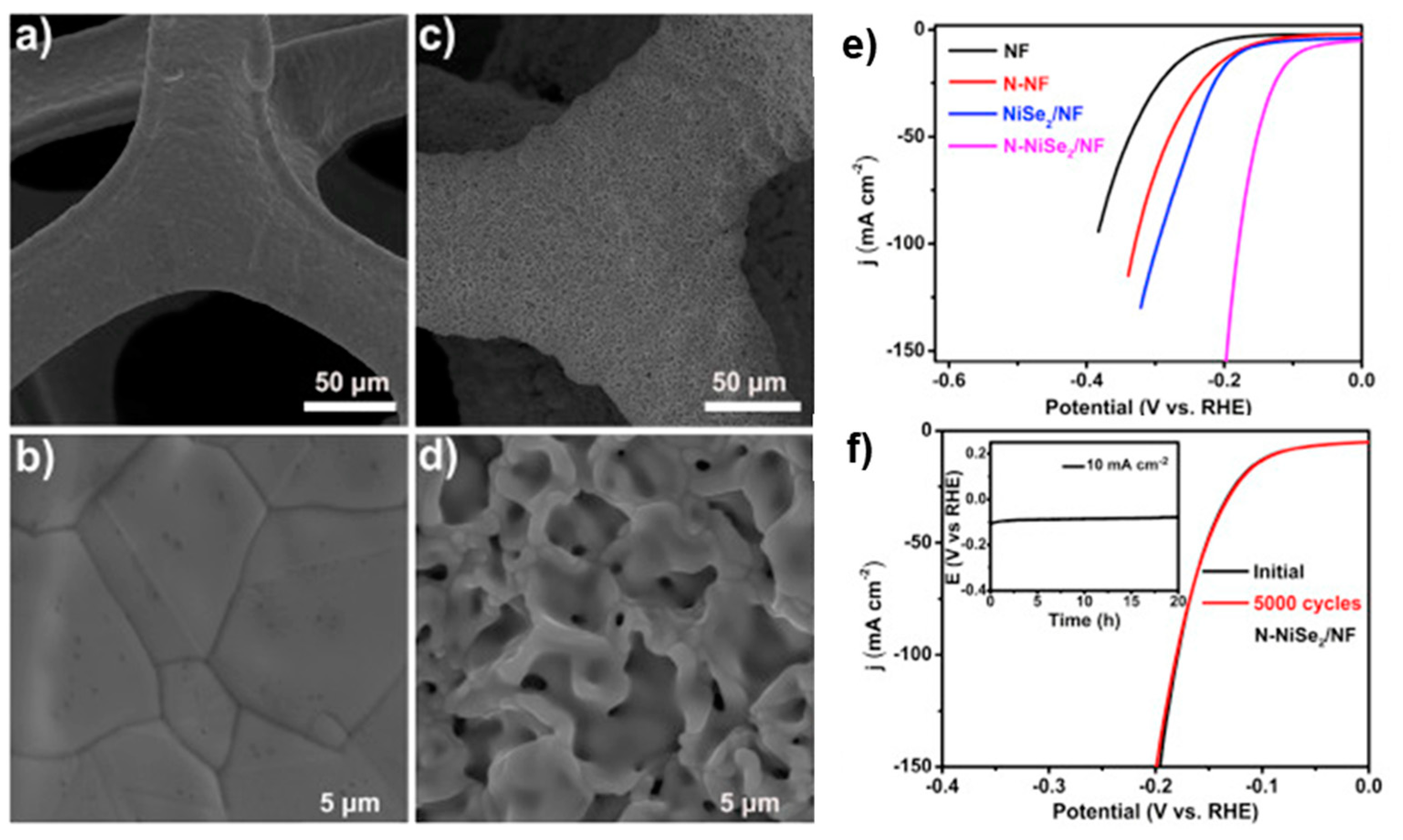
| N-NiSe2 | NF | Heat treatment (in NH3 atmosphere) | 1 M KOH | RT | −10 | 86 | 69 | Stable potential of ca. −100 mV at −10 mA cm−2 for 20 h. Negligible degradation after 5000 CV cycles (between −250 mV and 150 mV at 50 mV s−1) | [54] |
| NiS | Mild steel | Electrodeposition | 28 wt.% NaOH | 80 | −150 | 90 | 80.9 | - | [48] |
| NiSCo | Mild steel | Electrodeposition | 28 wt.% NaOH | 80 | −150 | 70 | 61.7 | Stable current density of ca. −95 mA cm−2 at −1.2 V for 2.2 h | [48] |
| NiCoP | NF | Hydrothermal treatment and phosphorization | 1 M KOH | RT | −10 | 98 | 68 | Stable after 300 CV cycles and no current density degradation (−10 mA cm−2) at 98 mV for 24 h | [40] |
| NiCoP | NF | Solvothermal and heat treatment | 1 M KOH | RT | −100 | 197 | 54 | Electrochemical stability for 28 h at 10 mA cm−2 | [39] |
| Ni3N NS | NF | Thermal treatment (in NH3 atmosphere) | 1 M KOH | RT | −10 | 34 | 54 | Stable current density of ca. −12 mA cm−2 at an overpotential of 174 mV for 8 h | [56] |
| NiMoN | CFC | Hydrothermal treatment (in NH3 atmosphere) | 1 M KOH | RT | −10 | 40 | 70 | Stable potential around −50 mV, at 10 mA cm−2 for 12 h | [64] |
| FeNi3N | NF | Heat treatment and calcination | 1 M KOH | RT | −10 | 75 | 98 | Stable potential and no degradation after 30 h at −50 mA cm−2 | [42] |
| MoC | GS | Carburization process | 1 M KOH | RT | −10 | 77 | 50 | Stable current density of ca. 15 mA cm−2 at 150 mV for 10 h | [58] |
| Mo2C | NCF | Polymerization process | 1 M KOH | RT | −10 | 100 | 55 | Electrochemical stability at 105 mV for 8 h and after 10,000 CV cycles (between −230 and 70 mV at 100 mV s−1) | [60] |
| Mo2C | HNCPs | Chemical vapor deposition and heat treatments | 1 M KOH | RT | −10 | 87 | 49 | Suitable stability: drop of 3.7% of the current density over 10 h | [59] |
| Alloy | (mV dec−1) | (mV dec−1) | (mA cm−2) | (mA cm−2) | (mA cm−2) |
|---|---|---|---|---|---|
| Ni | 125 | 120 | 0.03 | 21.3 | 38.9 |
| Co | 190 | 198 | 1.23 | 3.46 | 30.9 |
| Mo | 178 | 273 | 6.30 | 4.36 | 36.2 |
| Co30Ni70 | 130 | 206 | 1.58 | 5.24 | 58.9 |
| Ni30Mo70 | 75 | 112 | 7.24 | 138 | 708 |
| Co30Mo70 | 150 | 165 | 12.0 | 32.4 | 195 |
| Co10Ni20Mo70 | 130 | 221 | 60.2 | 234 | 577 |
| Fe10Co30Ni60 | 119 | 180 | 10.4 | 40.7 | 70.8 |
| Co10Fe30Ni60 | 102 | 180 | 9.77 | 32.4 | 77.6 |
| Composition | Support | Preparation Method | Electrolyte | T (°C) | j (mA cm−2) | ηOER (mV) | bOER (mV dec−1) | Stability | Ref. |
|---|---|---|---|---|---|---|---|---|---|
| Ni | Ni | - | 1 M KOH | RT | 10 | 403 | 72 | Poor stability, with current density decreasing from 7 to 3 mA cm−2, at 1.8 V for 25 h | [94] |
| Ni | Ni | - | 6 M KOH | 30 | 300 | 400 | - | - | [34] |
| Porous Ni | Porous Ni | - | 6 M KOH | 30 | 300 | 455 | - | - | [34] |
| NiO/Ni | Ni | Laser ablation | 1 M KOH | RT | 10 | 294 | 41 | Stable current density of around 7.5 mA cm−2, at 1.65 V for 25 h | [94] |
| NiO | GC | Drop-cast method | 1 M NaOH | RT | 10 | 420 | 62.4 | - | [95] |
| CoO | GC | Drop-cast method | 1 M NaOH | RT | 10 | 580 | 39.8 | - | [95] |
| CoOx | Co | Laser ablation | 1 M KOH | RT | 100 | 137 | - | - | [94] |
| MnO | GC | Drop-cast method | 1 M NaOH | RT | 10 | 490 | 88.3 | - | [95] |
| MnO2 | GC | Drop-cast method | 1 M NaOH | RT | 10 | 500 | 84.7 | - | [95] |
| MnOx | Mn | Laser ablation | 1 M KOH | RT | 100 | 203 | - | - | [94] |
| FeOx | Fe | Laser ablation | 1 M KOH | RT | 100 | 173 | - | - | [94] |
| Ni(OH)2 | NF | Activation process | 1 M KOH | RT | 10 | 288 | 40 | Stable potential of 1.57 V, at 100 mA cm−2 for 240 h | [68] |
| Ni(OH)2 | NF | Activation process | 1 M KOH | RT | 500 | 370 | - | Stable potential of 1.57 V, at 100 mA cm−2 for 240 h | [68] |
| Ni0.4Mo0.6O | CC | Thermal treatments | 1 M KOH | RT | 10 | 320 | 63 | Stable current density of 10 mA cm−2 at 1.57 V for 10 h. Slight shift to smaller current densities after 2000 CV cycles (between 0.40 and 0.84 V at 100 mV s−1) | [73] |
| Co1.4Ni0.6O2 | - | Co-precipitation and calcination | 1 M KOH | RT | 10 | 366 | 114 | Stable overpotential (only an increase of 15 mV) at 10 mA cm−2 for 8.3 h | [74] |
| NiFe2O4 | GC | Dealloying and annealing | 1 M KOH | RT | 10 | 412 | 57 | - | [80] |
| NiFe/NiFe(OH)2 | NF | Electrodeposition and oxidation | 1 M KOH | RT | 10 | 191 | 44.1 | Stable overpotential at 100 mA cm−2 for 8.3 h. No significant deactivation detected | [81] |
| NiFe(OH)2 | Ni | Electrodeposition | 6 M KOH | 30 | 300 | 365 | - | - | [34] |
| Ni(OH)2-Fe(OH)2 | CP | Electrodeposition and direct dropping | 1 M KOH | RT | 10 | 223 | 32.5 | Constant current density of 50 mA cm−2 for 100 h | [82] |
| 0.1-FeCoNiO | NF | Wet chemical method | 1 M KOH | RT | 10 | 240 | 36.8 | Stable potential of ca. 1.48 V at 10 mA cm−2 for 20 h. At high current densities (250 and 500 mA cm−2), the overpotential increases 160 mV after 10 h | [77] |
| CoMoO4-Ni(OH)2 | NF | Hydrothermal treatment, electrodeposition, sonication | 1 M KOH | RT | 100 | 349 | 67.6 | Electrochemical stability for 1000 CV cycles (between 0 and 0.8 V at 10 mV s−1) | [76] |
| NiFe LDH/rGO | GC | Solvothermal method and electrodeposition | 1 M KOH | RT | 10 | 245 | - | Electrochemical stability for 1000 CV cycles (between 1.10 and 1.85 V) | [85] |
| Ni-doped FeS | NF | Electrodeposition | 1 M KOH | RT | 100 | 255 | 58.3 | Electrochemical stability after 1000 CV cycles (between 0 and −0.35 V) | [87] |
| NiFeCoS | NF | Electrodeposition and solvothermal sulfurization | 1 M KOH | RT | 100 | 180 | 50.4 | Increase in the overpotential to 260 mV to attain 100 mA cm−2 after 500 CV cycles (between 0.1 and 0.5 V at 100 mV s−1) | [88] |
| Fe-NiFeCoS | NF | Electrodeposition and solvothermal sulfurization | 1 M KOH | RT | 100 | 230 | 113 | Decrease in the overpotential to 220 mV to deliver 100 mA cm−2 after 500 CV cycles (between 0.1 and 0.5 V at 100 mV s−1) | [88] |
| P-doped (NiFe)3S2 | NF | Hydrothermal treatment, phosphidation and sulfuration | 1 M KOH | RT | 10 | 196 | 30 | Electrochemical stability after 3000 CV cycles (between 1.2 and 1.6 V at 100 mV s−1). Stable current of 100 mA cm−2 at an overpotential of 295 mV for 15 h | [89] |
| NiFexP | NF | Dip coating and phosphidation | 1 M KOH | RT | 200 | 282 | 37 | Stable current density after 1000 CV cycles. Stable potential of around 1.7 V, at 10 mA cm−2 for 140 h | [54] |
| NiCoP | NF | Solvothermal and heat treatment | 1 M KOH | RT | 100 | 370 | 116 | Electrochemical stability for 28 h at 20 mA cm−2 | [39] |
| Fe-doped NiCoP | CC | Electrodeposition and phosphidation | 1 M KOH | RT | 50 | 293 | 37.8 | Electrochemical stability for 22 h at 10 mA cm−2 (minor increase of 12 mV in the overpotential) | [96] |
| Ni0.75Fe0.25Se2 | CFC | Hydrothermal treatment and selenization | 1 M KOH | RT | 35 | 255 | 47.2 | Stable potential of ca. 1.55 V, at 35 mA cm−2 for 28 h | [86] |
| FeNi3N | NF | Hydrothermal treatment and calcination | 1 M KOH | RT | 10 | 202 | 40 | Stable potential of ca. 1.55 V, at 50 mA cm−2 for 30 h | [42] |
| 316L SS | 316L SS | - | 1 M KOH | RT | 10 | 340 | 30 | Stable overpotential at 10 mA cm−2 for 20 h | [90] |
| 316L SS | 316L SS | Polished | 6 M KOH | 30 | 300 | 385 | - | - | [34] |
| SSM | SSM | Cathodization treatment | 1 M KOH | RT | 10 | 275 | 70 | Almost stable potential (<10 mV increase), at 10 mA cm−2 for 15 h | [91] |
| SSM | SSM | Cathodization treatment | 1 M KOH | RT | 100 | 319 | 70 | - | [91] |
| 316L SS | 316L SS | - | 1 M KOH | RT | 10 | 431 | 68 | Potential drop at 10 mA cm−2 after 5 h | [92] |
| 316L SS | 316L SS | Pulsed laser rusting | 1 M KOH | RT | 10 | 382 | 52 | - | [92] |
Publisher’s Note: MDPI stays neutral with regard to jurisdictional claims in published maps and institutional affiliations. |
© 2021 by the authors. Licensee MDPI, Basel, Switzerland. This article is an open access article distributed under the terms and conditions of the Creative Commons Attribution (CC BY) license (https://creativecommons.org/licenses/by/4.0/).
Share and Cite
Santos, A.L.; Cebola, M.-J.; Santos, D.M.F. Towards the Hydrogen Economy—A Review of the Parameters That Influence the Efficiency of Alkaline Water Electrolyzers. Energies 2021, 14, 3193. https://doi.org/10.3390/en14113193
Santos AL, Cebola M-J, Santos DMF. Towards the Hydrogen Economy—A Review of the Parameters That Influence the Efficiency of Alkaline Water Electrolyzers. Energies. 2021; 14(11):3193. https://doi.org/10.3390/en14113193
Chicago/Turabian StyleSantos, Ana L., Maria-João Cebola, and Diogo M. F. Santos. 2021. "Towards the Hydrogen Economy—A Review of the Parameters That Influence the Efficiency of Alkaline Water Electrolyzers" Energies 14, no. 11: 3193. https://doi.org/10.3390/en14113193