Article

A Study on Wear and Friction of Passenger Vehicles Control Arm Ball Joints

1
Department of Vehicles and Fundamentals of Machine Design, Lodz University of Technology, 90-537 Łódź, Poland
2
Department of Industrial Engineering and Systems, University of Sonora, Hermosillo 83000, Mexico
3
Institute of Vehicles and Construction Machinery Engineering, Warsaw University of Technology, 02-524 Warszawa, Poland
*
Author to whom correspondence should be addressed.
Energies 2021, 14(11), 3238; https://doi.org/10.3390/en14113238
Submission received: 1 February 2021 / Revised: 10 May 2021 / Accepted: 20 May 2021 / Published: 1 June 2021

Abstract

:
The following paper describes research on vehicle suspension elements: the ball joints. The worn surface roughness of selected ball pins and their bearings was compared in terms of vehicle mileage, utilization period, and car model. Ball pin roughness was measured using a scanning tunneling microscope (STM), whereas for the bearing surface, a profilometer was used. The aim of this study was to determine the resistive torque in an unloaded ball joint. Using the finite element method, models of the unloaded ball joint were analyzed in two scenarios: with and without interference between the worn ball and its bearing. Calculated values of resistive torques in the ball joint were compared, and recommendations were given relative to the mileage and the time after which it was necessary to perform verification or replacement of the ball joints.

1. Introduction

A vehicle suspension is defined as a group of elastic elements and rods. It connects axles or individual wheels with the frame or vehicle body. The function of a suspension is to absorb bumps coming from an unleveled surface by separating the wheels from the body of a car. Furthermore, its target is to assure the maximum comfort and protection of transported objects against shocks and harmful vibrations. Securing from too strong shocks has a huge influence on the durability of various mechanisms as well. One of the main components of the vehicle suspension is a control arm. The task of the control arms is to connect the stub axles with the body of a vehicle. There are three types of control arms distinguished—transverse, longitudinal, and diagonal, depending on the clamping and driving of the wheel. The control arm consists of a ball joint and one or two sleeves [1,2].
An interesting case is the McPherson strut suspension. Its characteristic feature is that there is only a lower ball joint. In this design, the lower ball joint is a follower, with the bottom of the strut connected directly to the steering knuckle and wheel. The bearing plate of the upper strut mount carries the vehicle’s weight, leaving the lower to act only as a pivot point. During preliminary observations, it was noted that there is some resistance when moving the ball joint pin relative to the ball joint body with the bearing (ball joint seat).
The technology, diagnosis, and repair methods of the suspension system as well as its components were presented and discussed in [3]. According to [4], the driveline and chassis components account for only 2% (approximately) of the total mechanical losses in passenger vehicles.
Yao et al. [5] proposed the direct tilt control (DTC) strategy allowing actively controlling the vehicle to tilt during a curve, which improved the vehicle performance during cornering. Such a control limited the occupant’s felt lateral acceleration and the lateral load transfer ratio during turning of the car and allowed proper path-tracking performance. However, it simultaneously changed the loading of the suspension ball joints.
Heißing and Ersoy [6] stated that the structure of the chassis itself is an origin of vibrations and sound. The suspension components are subjected to contact pressures and friction loads related to them in their contact zones. As a result, various coupled oscillation modes and self-noise are generated. The intensity of the transmitted oscillations/vibrations can vary in an unpredictable way during vehicle operation.
Nowadays, all of the car manufacturers put emphasis on enhancing the interior noise comfort of their cars. Paulraj et al. [7] claims that the Vehicle Noise Comfort Index (VNCI) is commonly utilized to estimate the sound features of vehicles. The interior vehicle sound comfort is indicated via a scale from 1 to 10. Major contributors to the sound quality are usually the sound volume and its sharpness in the frequency range of human hearing (20 Hz ÷ 20 kHz). A vehicle comfort level indication, based on artificial neural network, can be applied to determine the comfort level in vehicles. It can prevent situations where drivers and passengers are continuously exposed to high levels of noise and vibration, which as a result can cause their health deterioration.

1.1. Ball Joint

The ball joint of a control arm enables a rotational and oscillating movement of the joined components with respect to one another. The pivot point of the wheel lies on the axis of the pin. Additionally, the ball joint enables the angular deflection and transmits the shearing and longitudinal loads (along the pin axis). Since it performs rotationally oscillating movement, it is greased by a grease fitting or with graphite grease when the construction does not include a dedicated fitting. A ball joint can be loaded by axial force of both tension and compression nature. It can also be subjected to radial force, limiting the degrees of freedom to three-axis rotation direction without torque transmission [8]. The main components of the ball joint and their descriptions are presented in Figure 1 [1,9,10].
Interestingly, Farfan-Cabrera [11] reported that ball joints belonged to the main tribological elements causing resistance to motion in electric cars. Such a joint can be enhanced by altering the ball stud and bearing depending on its elasticity, surface roughness, resistance to temperature, and by improving the durability of the boot.
The construction aims at minimizing friction by polishing the pin of a ball joints. The grease applied to a joint and additional polytetrafluoroethylene (PTFE) [12], also called Teflon, layer on the pin also contribute to the smooth working and quick reaction time. The DLC cover on the ball joint pin [13] also allowed for extending the service life and lowering the friction. According to [8], the bearing of the ball joint can be also made of a synthetic resin. The anti-dust coating is mainly made of neoprene (CR), which is characterized by its protective features against temperature change, oil, and fuel as well as weather conditions. A nylon pad inside the nut prevents the elements from corroding and unscrewing.
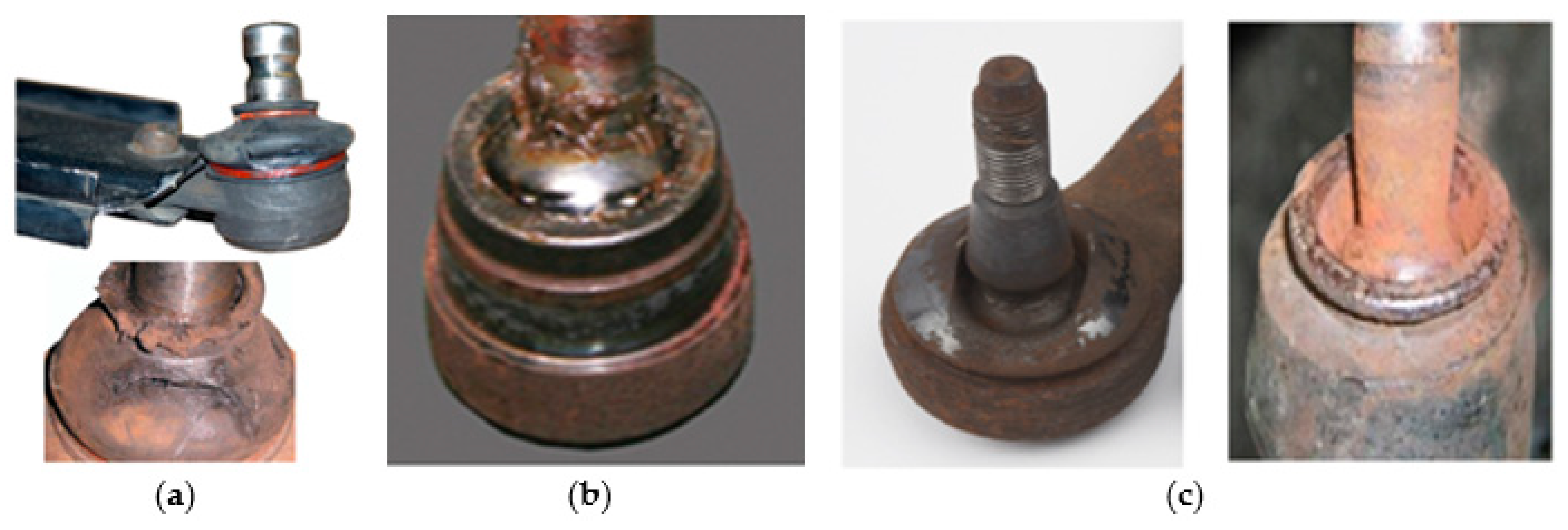
The most common ball joints defects include ripping the rubber cover (Figure 2), which results in water, sand, and other contaminants accumulating within the joint, causing faster excessive wear to the components. Additionally, water causes ball mandrel corrosion. The most severe consequence of a ripped rubber cover is grease leakage, which causes insufficient or even lack of lubrication. This usually results in a seized pin. Another defect of the ball joints is a bent mandrel caused by an impact of a wheel on an obstacle, for instance a curb or a bump. A rare case is the wear of both joined elements, which is a result of incorrect fitting of the pin (nut tightened with improper torque). Furthermore, such fault can cause pushing the seat of a stub axle out, and during driving on an uneven road, the pin may slip out from the seat. According to [14], symptoms of the control arm ball joints failures include the following:
-
Clunking noises from the car’s front suspension. The clearances between the worn ball joints and their socket increase. The joints start to rattle and knock during the up and down displacements of the suspension. Such joint knocks or clunks when traveling on rough roads, speed bumps, or when turning. The loudness of clunking increases with the wear of the ball joints or until they eventually completely fail and break.
-
Undue oscillations from the vehicle’s suspension. The loose worn ball joints vibrate excessively during driving. The vibrations stem from the affected ball joint from various sides of the car. Sometimes, the vibrations are felt via the steering wheel.
-
Wandering steering. The effect is that the vehicle steering drifts from one side to the other one on its own. When the ball joints operate efficiently, and the wheels are in good alignment, the steering wheel is simple and quick in response. Worn ball joints induce wandering of the car steering, requiring the driver to compensate. However, similar symptoms can also accompany the failures of control arm bushings [15], making the identification of the sound source difficult. The friction in the control arm ball joint can generate noise with high frequency in the order of several kHz, which can be difficult to hear by the driver or passengers.
Apart from the above-mentioned symptoms, driving with unstable ball joints puts excessive strain on other suspension components [16].

1.2. Studies on Ball Joints

There are several studies conducted on the tribological properties of the vehicle ball joints. Komori and Nagataki [13] studied the effect of application of the DLC coatings in tie rod end ball joints on handling, steering feel, and comfort of a car. It was found that the “polymer-like” DLC with higher hydrogen content exhibited stronger kinetic friction and stick-slip behavior at the static–kinetic transient phase, whereas for the “graphite-like” DLC with less hydrogen content, the kinetic friction had lower values, and the transient action was smoother. The “graphite-like” DLC allowed for an appropriate friction behavior for the ball joint, which resulted in better steering feel, vehicle stability, and ride comfort. The ‘polymer-like’ DLC with the excessive friction resulted in a sticky steering feel and an enhanced harshness with high frequency oscillations. Similar results are expected in the control arm ball joints coated with similar DLC layers.
For suspension ball joints, Omar [17] proposed tests measuring the rotation breakaway torque and rotation steady torque prior to a wear test and measuring the radial elasticity before and after a wear test. Such a wear test needs to be performed at a certain load and cycle along with the movement caused by rotational and articulation torques for the loading ball joint done simultaneously. In addition, ball joint spring travel and its elasticity should be tested.
Muscă et al. [18] elaborated the tester and experimental methodology for the motion resistive effort in car ball joints. Researchers reported that the ball joints manufacturers cannot properly control the clamping force of the ball joints during manufacturing. The tester was used for evaluation of the magnitude and evolution of internal friction between the joint’s surfaces. The tester allowed for controlling and maintaining a steady clamping force, which ensures a steady motion of the ball stud.
Watrin et al. [19] numerically and experimentally studied the failure of suspension ball joints. The wear process took place at the plastic socket/ball pin contact zone due to the complex loading of the ball joint during its lifetime. Both the contact pressure profile and the motions for the plastic socket elements were determined. The plastic socket wear was estimated using the modified Archard‘s law. It was found that the motion solicitations history strongly affected the overall wear.
Sahu et al. [20] analyzed the ball joint with a flexible socket model. The ball and socket were treated as composing ball joints and modeled as two single colliding components. A continuous model was used for the normal contact–impact loading. The energy dissipation during the mating of surfaces was estimated using the dynamic Hertz contact model. The Coulomb model was applied for the determination of the resistance to motion in the contact zone between the ball and socket joint.
Sin and Lee [21] utilized the flexible multibody dynamic model for simulations of the ball joint operation, taking into account caulking and pull-out strength.
Sun and Hao [22] elaborated on 2D finite element models for determination of the contact pressure for the non-conformal and semi-conformal contact of a ball and its socket. Researchers reported that contact character of a ball and its socket varied from the point one to the area one with the enhancement of the dimensionless curvature radius coefficient f, and f =0.536 was the critical parameter indicating the change.
Koumura and Shionoya [23] elaborated a dynamics model with series rigidity for an analysis of suspension friction. ’The stiffness features of the bushings, ball joints, and shock absorbers were mapped and arranged in a series to allow measuring the arm stiffness and the spring constant of the oil seals. One of the findings was that the friction coefficient affected both the damping coefficient and the spring constant of the suspension, particularly under the high series stiffness. The latter worsened the sprung motion for the frequencies above 15 Hz. An introduced modification of suspension improved the sprung motion above 2 Hz.
Rutci and Eren [24] determined experimentally and numerically the suspension ball joint pull-out force.
Yang [25] numerically studied a short–long arm type front suspension. Suspension bushings were treated as linear and nonlinear elements, respectively, and they were integrated with a flexible cradle and other suspension components. The ball joints included the lower and upper ball joints, and the outer and inner tie rod ball joints. It was found that the bushing stiffness and nonlinearity strongly affected the prediction accuracy of ball joint travels.
Burcham et al. [26] analyzed the failure of a car lower ball joint that fractured under a normal driving regime. It was found that fatigue was the most often failure mechanism. The finite element model was elaborated and utilized during performance analysis of the part under a normal loading condition.
During the modeling of behavior of worn ball joints, the results reported by Dowson and Wang [27] can be useful. The time-dependent elasto-hydrodynamic problem of a sphere moving normally, in approach and separation, to a plane surface was studied there. Interestingly, it was found that the impact time and the width of the conjunction are well predicted by the classical Hertzian analysis for dry contact.
Chung et al. [8] studied the role of plating thicknesses on ball studs in the wear process of the latter. It turns out that despite the positive role of such plating in corrosion resistance, the uneven thickness led to coarsening of the ball surface with time, thereby increasing the abrasion of the bearing contact zone. Apart from that, the wear of ball stud surfaces weakened the oscillating torque and enhanced the axial free gap. Such tendency became more clear for the higher thickness of the ball stud sphere platting. The uncoated ball joint was the best choice.
Studies on ball stud plating effects on gap variations in ball joints conducted by Raj [28] provided the same results as those described in [8].
When vehicles operate under environmental conditions of temperatures below 30 degrees and increased humidity, water percolates into the dust cap, leading to corrosion of the steel ball stud. The mentioned, very often occurring, axial and radial loads cause an abrading process of ball joint mating surfaces, which is manifested in an increase of clearance between them [29].
Such play often results in increased sound of the front lower control arm ball joints, which is especially felt under conditions of the vehicle passing through a speed bumps.
According to [30], minimizing the buzz, squeak, and rattle (BSR) is of great importance for the arrangement of car components and whole vehicle assemblies. BSR phenomena and their examples in vehicles, and also methods for their testing, analysis, and elimination were discussed there.
The suspension ball joints were modeled in various manners during numerical and experimental studies. The behavior and resistance of such ball joints were more often studied under loading by significant outer forces than under the lack of such a loading.
The main aim of this article was to estimate resistive torques in the unloaded worn ball joint with and without interface between its mating components.

2. Materials and Methods

2.1. Measurement of the Chosen Geometrical Parameters of the Ball Joints

The diameters of the new and the worn samples of ball joints were measured with a micrometer. The roughness of worn bearing surfaces was measured by means of a profilometer. The polyether ether ketone (PEEK) and polyoxymethylene (POM) samples of bearing materials were prepared by cutting them from the actual bearing component, and its roughness was measured using a profilometer. The roughness of worn surfaces for steel balls were obtained by scanning tunneling microscope (direct current operation, needles made of Pt-Ir wire with diameter equal to 0.25 mm). Scanning was conducted at atmospheric pressure and in room temperature.
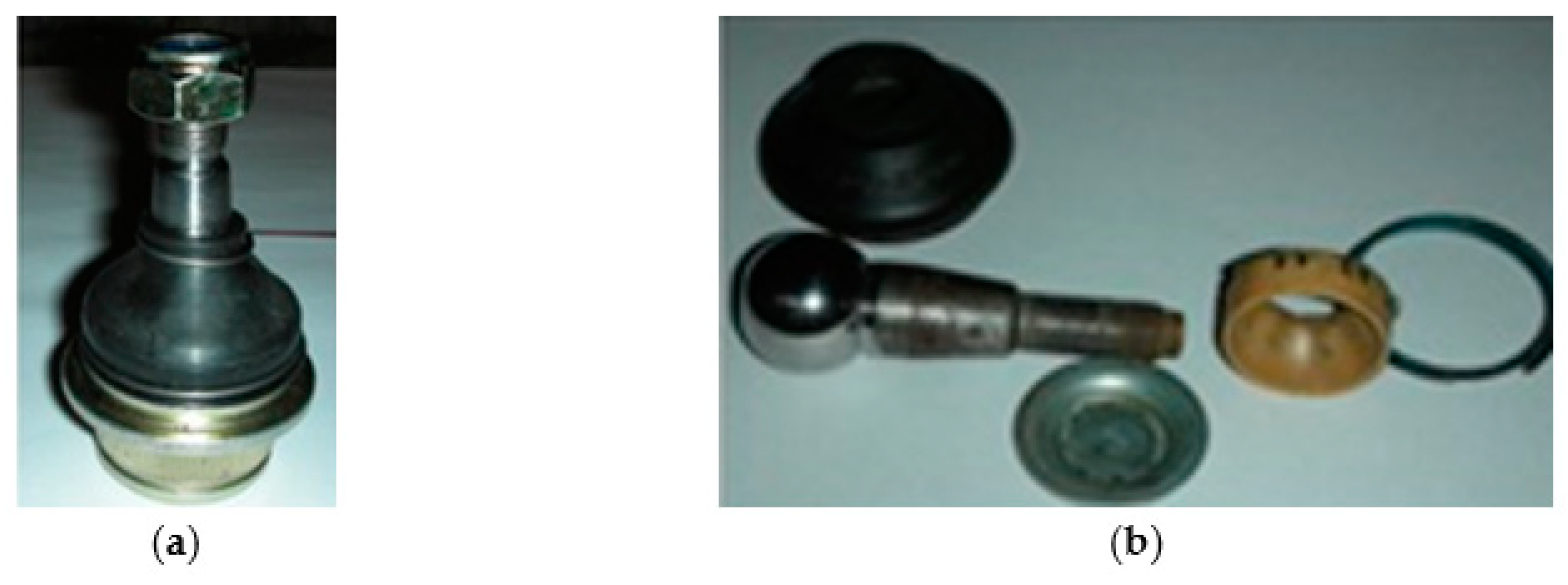
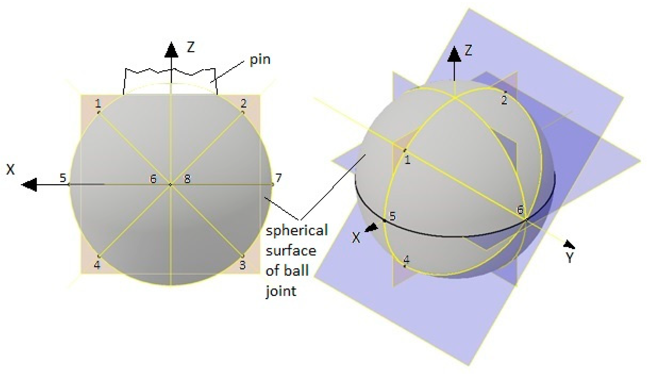
To estimate the roughness parameter, used ball joints of different manufacturers (Figure 3b) were collected. The ball joints were utilized in vehicles of different mileage and different driving conditions—urban, extra-urban, and combined. What is more, the short-used equivalents of such ball joints were bought as well (Figure 3a). Obtained STM images enabled the determination of peak roughness of examined elements. For each sample, the roughness was measured at 8 points on a spherical surface. Their angular positions are shown in Figure 4, although they were chosen arbitrarily so that the measurement points were within wear areas in of worn pins. Based on the results, the mileage and the exploitation time after which such a component requires verification and a presumptive replacement were estimated.
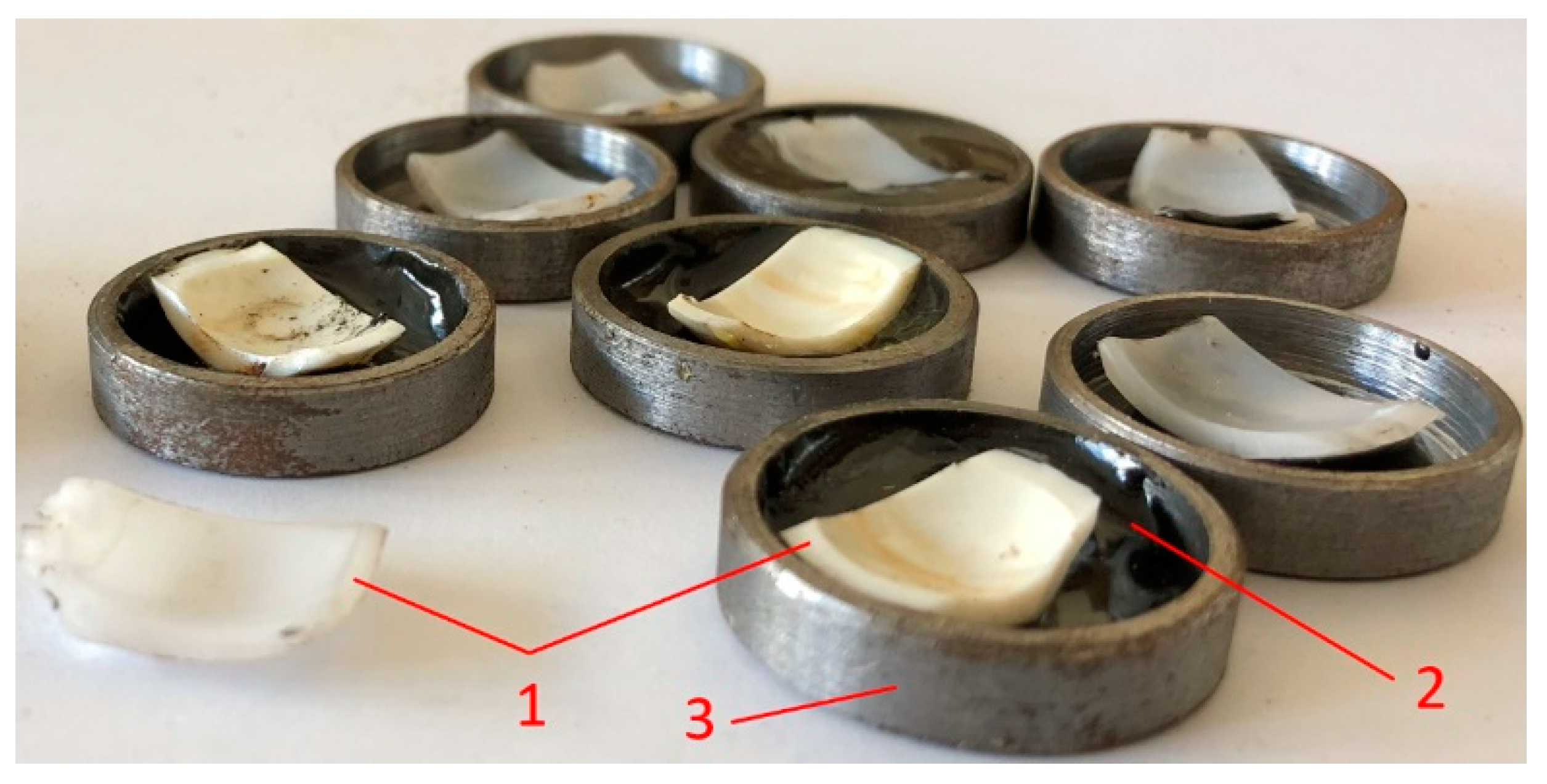
Figure 5 shows some exemplary samples comprised of cut fragments (1) of POM and PEEK bearings of the analyzed ball joints. Such fragments were glued to the steel holders (3) with a two-composite glue (2). The holders facilitated the positioning of the tested samples in relation to the profilometer head. Roughness measurements were conducted at various locations of the fragments (1), especially in their middle zones.

2.2. Experimental Determination of Material Models Parameters for Ball Joint Pin and Ball Joint Bearing

Firstly, an assumption was made that ball joint pin was made of hardened steel without any coating. The estimation of Young modulus and Poisson number for the ball bearing material was done using the tester presented in Figure 6.
The tester comprises of steel tilt arm (2) supported by needle bearing (4) on the hardened and ground steel bolt (3) fixed to the support (1) made of steel plates connected either by welding or by means of bolts and pins (removable plates). On the tilt arm, two bearing needles were placed: the (5) one mating with the adjustment screw (11) being fixed with a locking nut (10), and the (6) one mating with the measuring tip of a micrometer depth gauge (16). The tilt arm (2) was loaded by the force F from weights placed on the holder connected through the string with a hoop pin (9). Such a hoop comprises of the steel pins (6) and (9) and two steel cords (8). The adjustment screw (11) and a locking nut (10) were isolated against the support (1). The screw (11) and tilt arm (2) were electrically connected to the circuit containing battery (14) and control light (15). In case of contact between polished front plane of the screw (10), the roller needle (5), and the tilt arm (2), the electric circuit is closed, and then, the control light turns on. The position of the adjustment screw (11) was determined using an aligning bearing roller (12) positioned between the tilt arm (2) and support (1) in the predetermined place marked using paint. The tilt arm was loaded only by weight of loading unit assembly (without weights) to remove the radial gap in the needle bearing (4). In such a position, the measuring tip of a micrometer depth gauge (16) was initially adjusted to the roller needle (7), and its indication u u n l o a d e d 0 was recorded. Then, the micrometer depth gauge (16) was removed, and the tilt arm was rotated slightly up around the pin (3) to allow for replacement of the aligning bearing roller (12) by a test sample (13) of the ball joint bearing material placed in the cylindrical seat (17) made in the support (1). Then, the depth gauge micrometer (16) was put back into the slot (18) milled in the support (1) in a predetermined place marked with paint. The position of the measuring tip of a micrometer depth gauge (16) was adjusted to the position of the bearing needle (7), and its indication u u n l o a d e d was recorded. Then, the loading unit assembly was loaded through addition of the consecutive weights placed on the holder. After each addition, a micrometer depth gauge (16) was once again adjusted to the position of the bearing needle (7), and its indication u l o a d e d was recorded. Then, the obtained indications were used to determine the vertical displacement of the material at the contact point between the tilt arm and tested sample, according to the following equation:
u X     u l o a d e d u u n l o a d e d · k t i l t a r m
where
k t i l t a r m = 1   cm / 21   cm —single-sided lever (tilt arm) ratio.
If u u n l o a d e d u u n l o a d e d 0 0 , that was included in the model for determining the deformations of the modeled sample of the ball joint bearing material.

2.3. Numerical Determination of the Modeled Material Sample Deformations of the Ball Joint Bearing

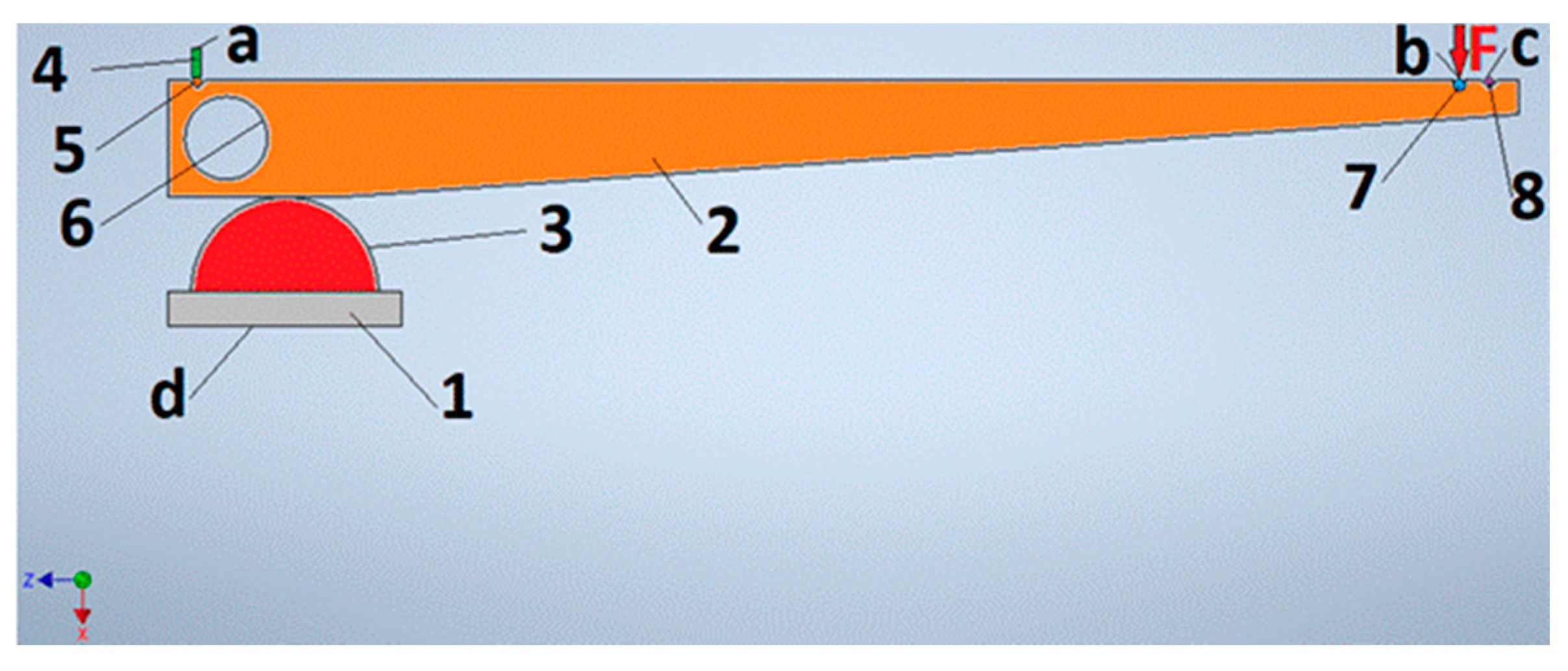
The numerical model of the sample deformations of the ball joint bearing material is presented in Figure 7. It is comprised of a steel support (1) being in frictional contact with the tested semispherical bearing material sample (3). The outer spherical surface of the tested material sample was in frictional contact with the steel tilt arm (2). It was fixed around the axis of its nondeformable hole (6) for the needle bearing placement. The tilt arm (2) was in frictional contact with the steel bearing needle (5), which was mating frictionally with the bottom plane of the fine threaded screw tip (4). The upper plane of the tip was fixed. The tilt arm (2) was also in frictional contact with the steel pin (7) of a loading unit assembly hoop with weights. The pin was loaded by the force F from such weights. The tilt arm (2) was also in frictional contact with the steel bearing needle (8). The displacements along the X-axis of a cylindrical surface of such a bearing needle were compared with values obtained during measurement.
The model took as an input measured geometric parameters of the material samples and the model (e.g., isotropic and linear) of the material with the given values of Young’s modulus as well as Poisson’s number. Those sample material parameters were initially assigned a theoretical value. Then, they were adjusted to obtain displacements along the X-axis of a cylindrical surface of a bearing needle (8) close to the average value from these obtained from the measurement.
In order to control the deformations of the material sample, the vertical displacement of the sample (3) and the contact pressure in the contact zone with the tilt arm (2) were also determined from the model.
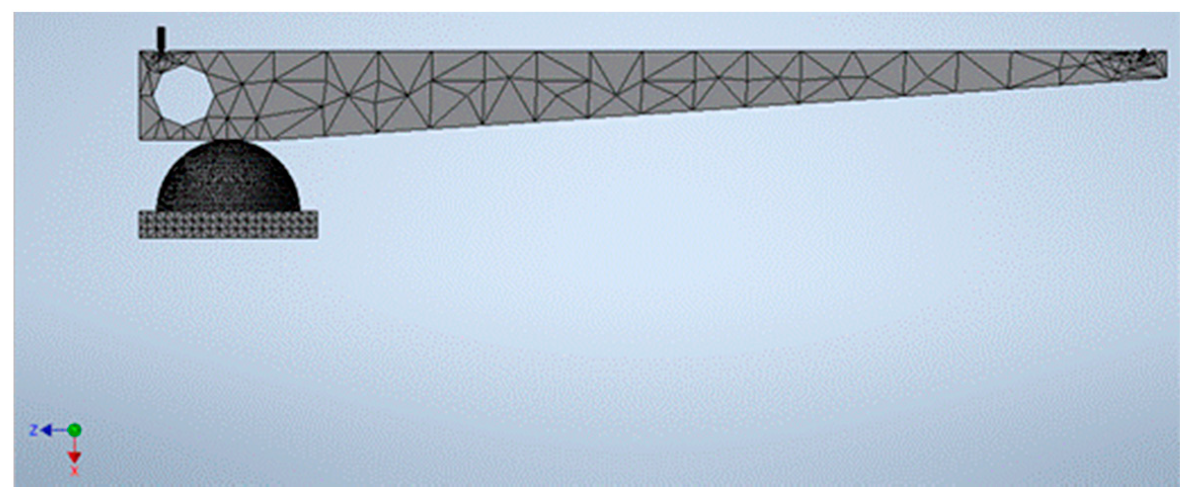
The mesh of finite elements analysis is shown in Figure 8. To ensure the convergence of numerical calculations for all contact zones, the frictional contact elements were assigned a value of the friction coefficient equal to 0.01. The value of this friction coefficient was dictated by the commonly used practice during numerical calculations, aimed at stabilizing the iterative process of obtaining a solution, consisting of introducing a small value of the so-called numerical friction, which, as a rule, has no pure physical interpretation.

2.4. Friction Coefficient Determination between Steel and Ball Joint Bearing Material

Marques et al. [31] found that in mechanical joints, a static friction model with elimination of the discontinuity at zero velocity was usually a good choice. However, a dynamic friction model was needed for systems exposed to highly variable normal loads, such as impact conditions occurring in suspension ball joints, for example.
For various vehicles configurations, the method described in [32] is usually used. Such a method comprises an algorithm for friction and wear behavior determination of greased plastic socket suspension joints. It also allows validating these greases and quality inspection for such lubricants under high-frequency oscillations utilizing the SRV tester.
Due to lack of access to a SRV test machine, the other method was used to determine the resistance to motion in contact between the steel ball joint pin and ball joint bearing material. To estimate the values of the friction coefficient, a simple tester was prepared (Figure 9). It utilizes an adjustable tilting plane (2), which was mounted on a pin (5) attached to the support (1) and symmetrically positioned relative to the mean symmetry plane of the support. The upper steel surface of the tilting plane (2) was ground and polished. Before the measurement, it was degreased and decontaminated with 96% alcohol. The tilt angle α (Figure 9b) was changed with a turnbuckle (4) with a self-locking thread. The nuts on both sides of the turnbuckle were integrated with the yokes (6) and (7) attached to the bolts (8) and (9) attached to the tilting plane (2) and to the support (1), respectively. The tilt angle α was measured with a protractor (3) attached to the support (1). The edge of the semisphered sample (10) made of the bearing material was ground with sandpaper in the cut plane (11). Before measurement, the entire test sample was again degreased and decontaminated with 96% alcohol. Measurements were made in a laboratory room in a stable room temperature and 40% air humidity. After placing the sample evenly, in the conditions of contact between the upper surface of the tilting inclined plane (2) and the plane (11) of the sample, the inclined plane (2) was raised with a turnbuckle (4) until the sample (10) starts to slide down the plane. A corresponding tilt angle α was registered. Then, the sample was turned upside down, and a similar measurement was made. The measurements for each case were repeated 5 times by rotating the sample along the axis perpendicular to the inclined plane (2).

2.5. Tribological Model

Contact between the ball joint pin and its bearing was modeled as a contact of the smooth elastic steel ball and smooth deformable POM bearing. The bearing was placed in a steel ball joint body (assumed as a rigid one) and secured against falling out by the local crease of the body material. Thanks to this, a small interference was created between the bearing and the body, and between the bearing and the ball joint pin. The existence of this interference can be evidenced by a small resistance occurring sometimes during the movement of the ball joint pin against its bearing [33].
The resistive torque M r e s i s t generated during the existence of small interference between the steel ball and POM bearing can be estimated from Equation (2):
M r e s i s t = μ · p i n t e r · A p a r t i a l · R a v e r = μ · p i n t e r · 0.7 · 4 · π · R b a l l 2 · π 4 R b a l l ,
where
p i n t e r —contact pressure resulted from the interference of the steel ball and POM bearing,
μ = 0.12—average friction coefficient between the steel ball and bearing made of POM with PTFE [34],
A p a r t i a l —area of contact zone where friction exists between the steel ball and POM bearing,
R a v e r —averaged radius between contact zone points and the axis of ball joint rotation,
R b a l l = 27/2 mm = 13.5 mm—the radius of the ball in the analyzed ball joint.
Due to the wear process, the interference can become smaller and smaller. However, the resistance between the ball surface and bearing can still occur. In this case, to estimate the resistance torque in the contact zone, another model was assumed. Particularly, it was assumed that the interaction between the steel ball and PTFE played the most significant role, and the effect of POM became much smaller.
The resistive force F r e s i s t generated during sliding the ball joint pin against its bearing was calculated from Equation (3) [35]:
F r e s i s t = F d e f o r m + F a d h e s i o n + F f l u i d ,
where
F d e f o r m —force generated due to bodies deformation,
F a d h e s i o n —force generated due to adhesion in the contact zone,
F f l u i d —force generated due to fluid shear stress.
It was assumed that the work done by the internal forces during deformations of mating bodies is turned into heat.
Due to the existing contact pressure, soft PTFE asperities deform plastically, and they fill partially the existing space between the bearing and the ball. The remaining space is filled with lithium grease. An average contact surface was established, which was approximated as a rigid spherical surface. The existing asperities made both of PTFE and steel can be modeled by hemispheres or spherical caps. The obtained values of the average contact pressure between the ball and its bearing can allow for determination of the initial position of each analyzed PTFE hemisphere against a rigid plane tangent to the mentioned rigid spherical surface.
Such a rigid spherical surface can be useful also during further calculations of work made by internal forces generated during bodies deformations. It was assumed that almost rigid steel hemispheres modeling asperities existing on the ball surface can protrude above the rigid spherical surface. The initial positions of such steel hemispheres against the rigid spherical surface were assumed to be the same as in the case of PTFE ones. It allows for a simplification and limits the amount of calculations [36].

2.6. Contact Pressure Determination in the Zone between Ball Joint Pin and Its Bearing

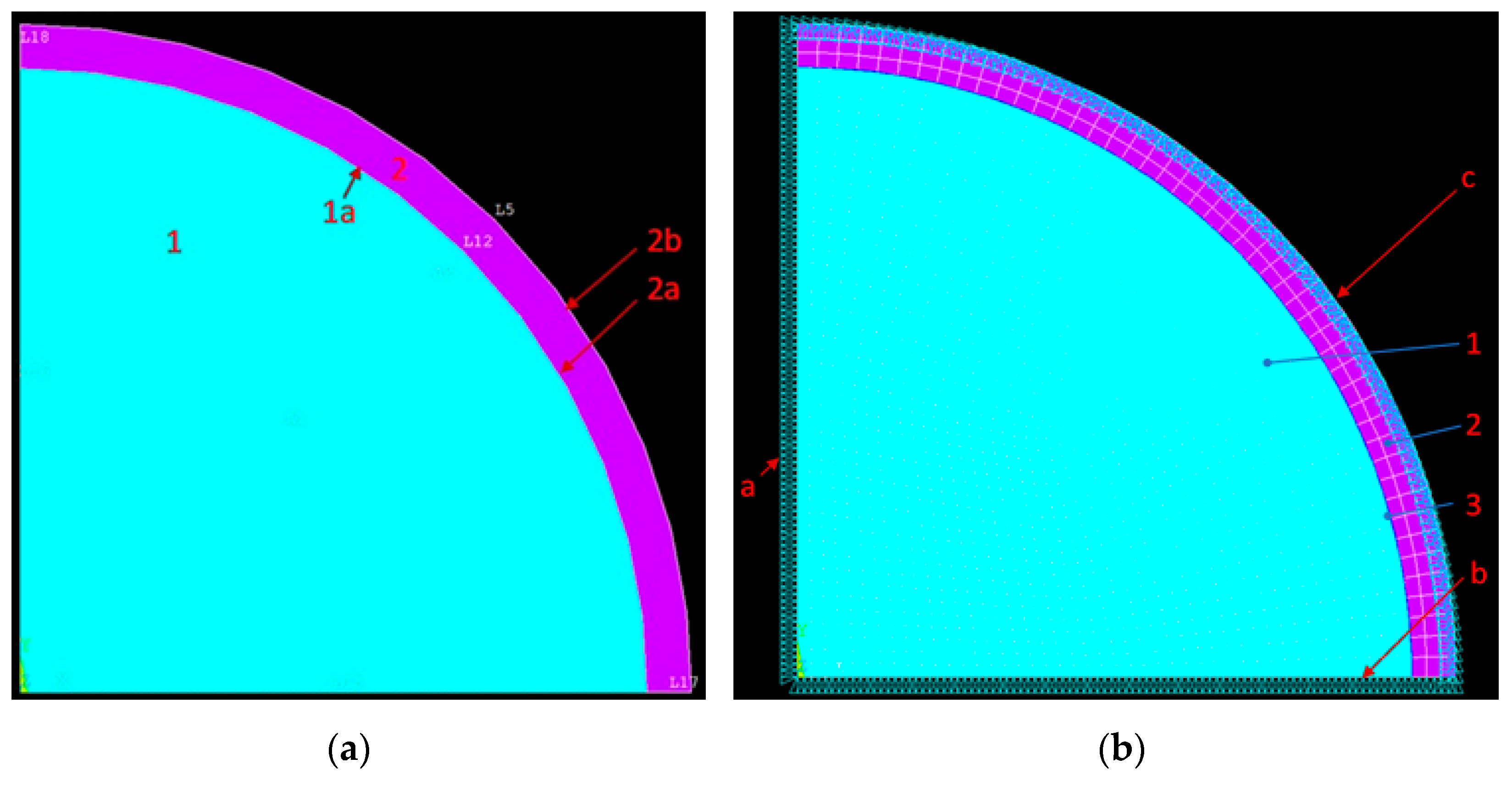
To determine the contact pressure p i n t e r in contact between the ball joint pin and its bearing, the finite element model was utilized. It was assumed that the ball 1 is a solid sphere and is concentric with inner 2a and outer 2b surfaces of the bearing 2, also being a solid sphere (Figure 10a).
The outer bearing surface 2b was rigidly connected to the nondeformable ball joint body—the outer bearing surface 2b was fixed (boundary condition ‘c’ in Figure 10b) in the model. It was assumed that the interference between ball 1 and bearing 2 reaches its maximum value for the H7/j6 fit. To simplify calculations, the axial symmetry along the Y-axis (boundary condition ‘a’ in Figure 10b) and planar symmetry (boundary condition ‘b’ in Figure 10b) against the XZ plane was included in the model. The mesh of finite elements (Figure 10b) was created automatically by the Ansys software. In the presented analysis, the axisymmetric case [37] of nonlinear contact frictional type was utilized. To stabilize the conversion of numerical calculations, a low value equal to 0.01 of the friction coefficient was introduced.
The material model for steel, assumed for each calculation process in the paper, was isotropic and linear with the Young modulus E1 of 210,000 MPa and the Poisson number ν1 of 0.3 [35]. In addition, the linear material model of POM was assumed for the calculation process. Its Young modulus E2 was 3000 MPa and the Poisson ratio ν2 was 0.4. [35].
During estimation of contact pressure p i n t e r , the PTFE layer was omitted due to its minor impact on the pressure.
Due to the wear process, the interference can become smaller and smaller. However, the resistance to motion between the ball surface and bearing can still occur. Accounting for the actual wear process in the frictional model would require the use of a 3D model of a ball joint. Although the 2D model cannot represent exactly the actual shape of the worn surfaces, nevertheless, it can be used as an equivalent model in which the progressive wear is modeled in successive time moment t i using the reduction of the initial interference Δ R between pin ball end and its bearing by a value Δ Δ R calculated from Equation (4):
Δ Δ R = i · Δ t · Δ R L v a v e r ,
where
L —vehicle mileage,
v a v e r —average vehicle speed during its lifecycle,
Δ t —assumed time step,
i —number of time steps during calculations taking into account the wear process in the analyzed ball joint contact zone.
As the value of initial interference fulfills the condition Δ R R b a l l , Equation (4) can be rearranged as follows:
Δ Δ R i · Δ t L v a v e r · Δ V 4 · π · R b a l l 2 ,
where
Δ V —volumetric wear of ball joint pin and bearing.
It was assumed that number of time steps i fulfills condition (6):
Δ R i · Δ Δ R R a b a l l + R a b e a r i n g ,
where
R a b a l l —Ra parameter of ball roughness,
R a b e a r i n g —Ra parameter of bearing roughness.
After reaching the maximum value of number i to estimate the resistance torque in this contact zone, the other model was utilized, which was described in the following subsections.

2.7. Resistive Force Determination Generated Due to Bodies Deformation

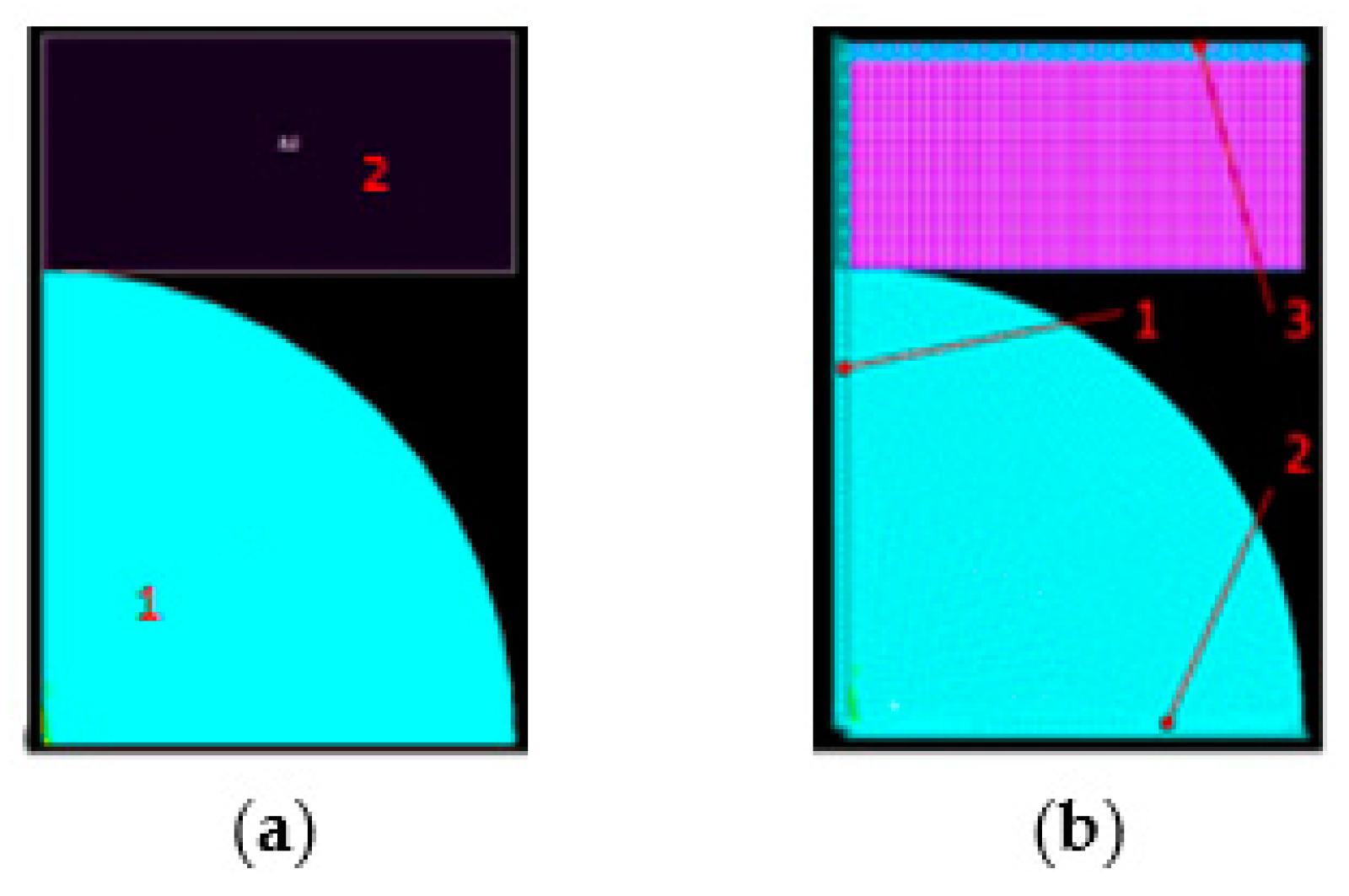
In order to determine the work done during deformation of mating bodies, the FE model was composed of a fixed hemisphere made of steel (on the bottom of Figure 11a) and of a hemisphere made of PTFE (on the top of Figure 11a) moving against the steel one. Modeling of the mechanical behavior of polytetrafluoroethylene (PTFE) was discussed in [38].
To simplify the calculations, the symmetry plane (boundary condition (1)) was used in the model (Figure 11b—left). The mesh of finite elements (Figure 11b) was generated by Ansys software. The top plane of the hemisphere made of polyoxymethylene moves with the distance of 0.4 μm (boundary condition (3) against the fixed (boundary condition (2) steel hemisphere along the symmetry plane (Figure 11b—right).
The material models for steel and for polyoxymethylene were the same as in the previous case of analysis. According to [37], the material model of PTFE comprised linear elasticity constants, such as the Young modulus E3 of 482 MPa [39] and the Poisson number ν3 of 0.45 [39]. That model comprised also the Extended Drucker–Prager material model constants, such as C 1 = 3 [39]—the pressure sensitivity and C 2 = 0 [39,40]—uniaxial yield stress. The internal forces Fxi, Fyi, and Fzi and displacement forces xi, yi, and zi acting in the X, Y, and Z directions, respectively, were averaged over the volume of each i-th element. Their values were used to determine the work done during deformation of mating bodies and then to estimate the resistive force due to deformations of mating bodies.
The resistive force F d e f o r m generated due to deformation was estimated from Equation (7):
F d e f o r m i = 1 i = N F x i x i + i = 1 i = N F y i y i + i = 1 i = N F z i z i Δ x ,
where
Fxi, Fyi, Fzi—internal forces acting in the X, Y, Z directions, respectively,
xi, yi, zi—displacements in the X, Y, Z directions, respectively,
Δx—average displacement of polyoxymethylene hemisphere against the steel hemisphere in the X direction.
The number n of modeled hemispheres was estimated from Equation (8):
n = A p a r t i a l A d i s t = 0.7 · 4 · π · R b a l l 2 80 · R a 2 ,  
where
Ra—equivalent vertical roughness parameter (it was of 0.2 μm—as obtained from the measurement),
A p a r t i a l —area of contact zone where friction exists between the steel ball and PTFE layer,
A d i s t —area of square in the vertices of which there are centers of hemispheres modeling asperities; it was assumed that the side of this square was of the length equal to the horizontal roughness parameters S m 80 · R a ,
R b a l l = 27/2 mm = 13.5 mm—the radius of ball in the analyzed ball joint.
The resistive torque M d e f o r m from the forces F d e f o r m generated due to deformations was estimated from Equation (9):
M d e f o r m = n · F d e f o r m · R a v e r = n · F d e f o r m · π 4 R b a l l ,
where
R a v e r —averaged radius between the force F d e f o r m and the axis of ball joint rotation.

2.8. Determination of Resistive Force Generated Due to Adhesion

The resistive force F a d h e s i o n generated due to adhesion was estimated from Equation (10) [35]:
F a d h e s i o n = τ S · A r e a l = τ S · π r r e a l 2 ,
where
τ S = 50 MPa—shear stress for adhesion [35],
r r e a l —radius of contact zone between the polyoxymethylene hemisphere (or spherical cap) and the mentioned earlier rigid sphere surface when plastic stresses are reached in all contact zones.
The resistive torque M a d h e s i o n from the forces generated due to adhesion was estimated from Equation (11):
M a d h e s i o n = n · F a d h e s i o n · R a v e r = n · F a d h e s i o n · π 4 R b a l l .
To determine the radius of the contact zone between the polyoxymethylene hemisphere and the mentioned earlier rigid sphere surface, when plastic stresses are reached in all zones, the finite element model was elaborated. In the model instead of a rigid sphere surface, the rigid plane tangent to it was considered. More precisely, the rigid plane was modeled by the face of rigid cylinder 2 coaxial with polyoxymethylene hemisphere 1 (Figure 12a) or spherical cap 1 (Figure 13a).
To simplify calculations, the axial symmetry along the Y-axis (boundary condition (1) in Figure 12b and Figure 13b) was included in the model. The bottom plane of the polyoxymethylene hemisphere or spherical cap was fixed in the Y direction (boundary condition (2) in Figure 12b and Figure 13b). The upper face of the almost rigid steel cylinder moves toward the polyoxymethylene hemisphere or spherical cap in the Y direction (boundary condition (3) in Figure 12b and Figure 13b), until the maximum yield strength is reached in all contact zones. The material models for steel and for polyoxymethylene were the same as in the previous analysis. The mesh of finite elements (Figure 12b and Figure 13b) was generated automatically by Ansys software.

2.9. Determination of Resistive Force Generated Due to Fluid Shear Stresses

To calculate the resistive force generated due to fluid share stresses, an assumption was made that the plane (1) is sliding with the speed V against the fixed hemisphere (2) (Figure 14). The volume between hemisphere (2) and its projection (4) on the mating plane is filled with lithium grease (3).
The hydrodynamic pressure distribution p(r, θ) in the grease calculated in the polar coordinate system is obtained from Equation (12) [41]:
p r , θ = 24 5 η V R 2 r 3 c o s θ + c   c o s h 3 θ .
The first term in Equation (12) is the Sommerfeld solution arranged in polar coordinates [40] (Figure 14b).
Obtained values of hydrodynamic pressure can be positive, zero, or negative. The latter indicate the occurrence of cavitation in the volume between the hemisphere and its projection on the mating plane. As the lithium grease cannot carry negative pressures, it was assumed that the calculated hydrodynamic pressure is then equal to zero. The occurrence of cavitation results in numerical problems due to the complexity of this phenomenon. In the real case, the evidence of the cavitation lines was found experimentally for large values of ηVR2 [40].
For smaller values of ηVR2, film rupture occurs later, and Formula (12) is unable to describe it [41]. To simplify the calculations, it was assumed that the hydrodynamic pressure distribution in the grease was roughly estimated from Equation (13) [41]:
p r , θ = 24 5 η V R 2 r 3 c o s θ .
The resistive force F f l u i d generated due to fluid shear stresses was estimated from Equation (14) [35]:
F f l u i d = τ x r A = η u x a v e r R a + R a 2 · p i n t e r R a · R a 2 ,
where
η = 0.75 Pa∙s—dynamic viscosity of the lithium grease [35],
τ x r —fluid shear stress in xr plane,
p i n t e r —average contact pressure between the ball and its bearing in the ball joint.
u x a v e r —average velocity of points on the ball surface, estimated from Equation (15):
u x a v e r = ω R a v e r = ω π 4 R b a l l ,
where
ω—angular speed of the rotating ball.
The resistive torque M f l u i d from the forces generated due to fluid shear stresses was estimated from Equation (16):
M f l u i d = n · F f l u i d · R a v e r = n · F f l u i d · π 4 R b a l l .

3. Results

3.1. Ra Profile Measurements

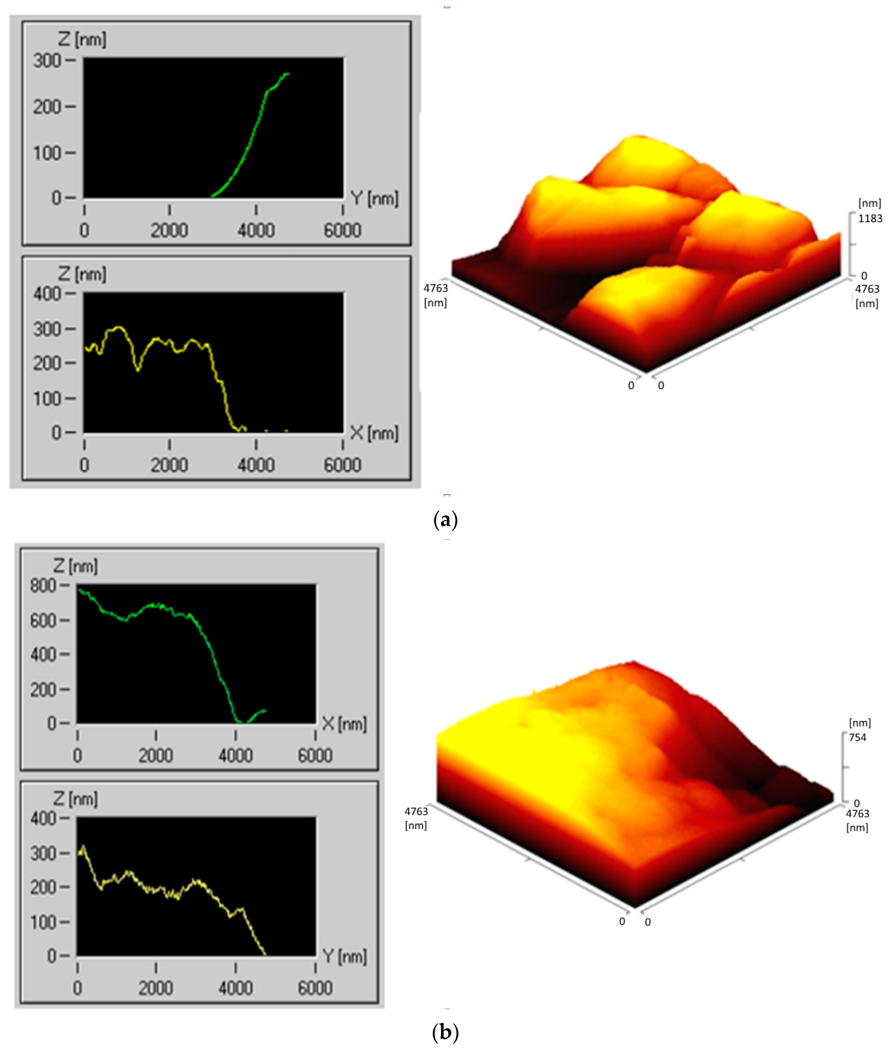
For each analyzed ball joint (Figure 15, Figure 16 and Figure 17), the authors present only the cases with the highest value of Ra parameter measured in points 1–8, as presented in Figure 4. Figure 15 describes the results of the Ra profile measurements for a Peugeot 206 vehicle. Ball joints mounted by the manufacturer in Peugeot 206 exhibited a higher accuracy of mating surfaces and application of better materials than the replacement ones. It was observed that for the original pins, the surface roughness (Ra parameter) was below 400 nm (Figure 15a—mileage: 30,000 km, vehicle age: 2 years, Figure 15c—mileage: 115,000 km, vehicle age: 8 years, and Figure 15d—mileage: 90,000 km, vehicle age: 7 years). The ball joint bought as a replacement part (Figure 15b) was characterized by a roughness of approximately 800 nm (mileage for this pin was 40,000 km and the vehicle age was 3.5 years). All analyzed vehicles operated in combined cycles. Interestingly, it was noticed that the factory-mounted joint was of significantly lower wear than its substitute, considering that its time of utilization was twice as long.
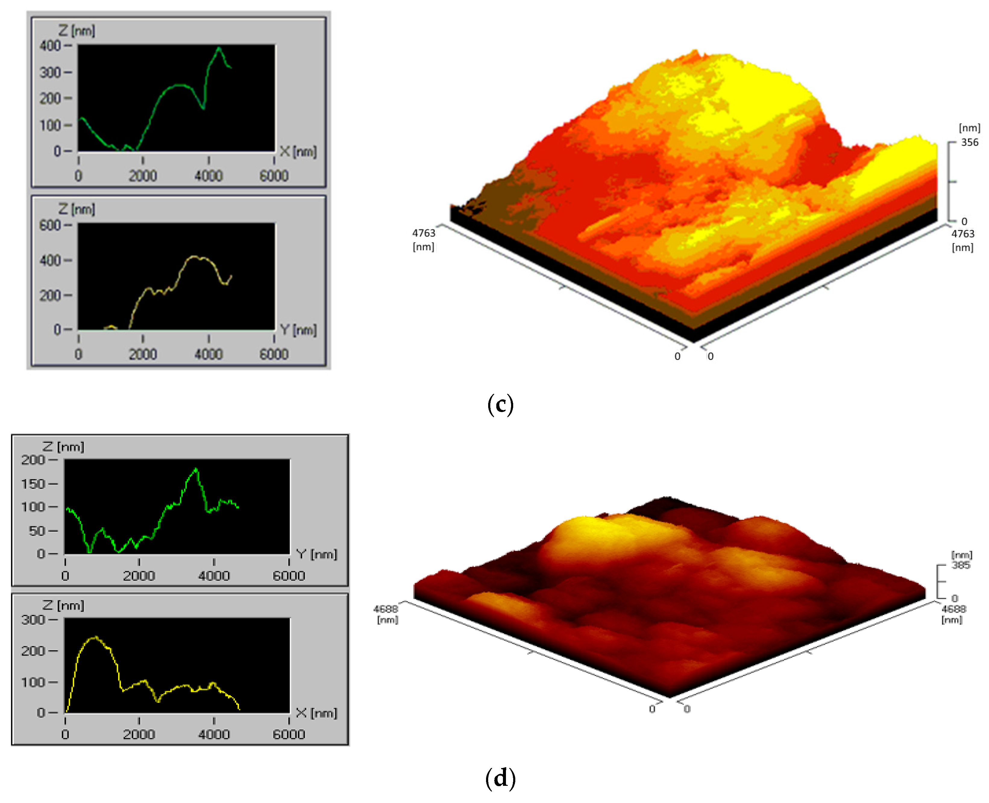
Figure 16 presents ball joints removed from the Mercedes Sprinter. Figure 16a shows a ball joint mounted on the right side, whereas Figure 16b includes the one on the left side of the car. Using roughness profiles, it was observed that on the right ball joint, the roughness was twice as high. It might be caused by the higher number of impacts, since it is a delivery vehicle, and it frequently approaches the curbs with the right side. In addition, the pavement condition in Poland was often of poor quality.
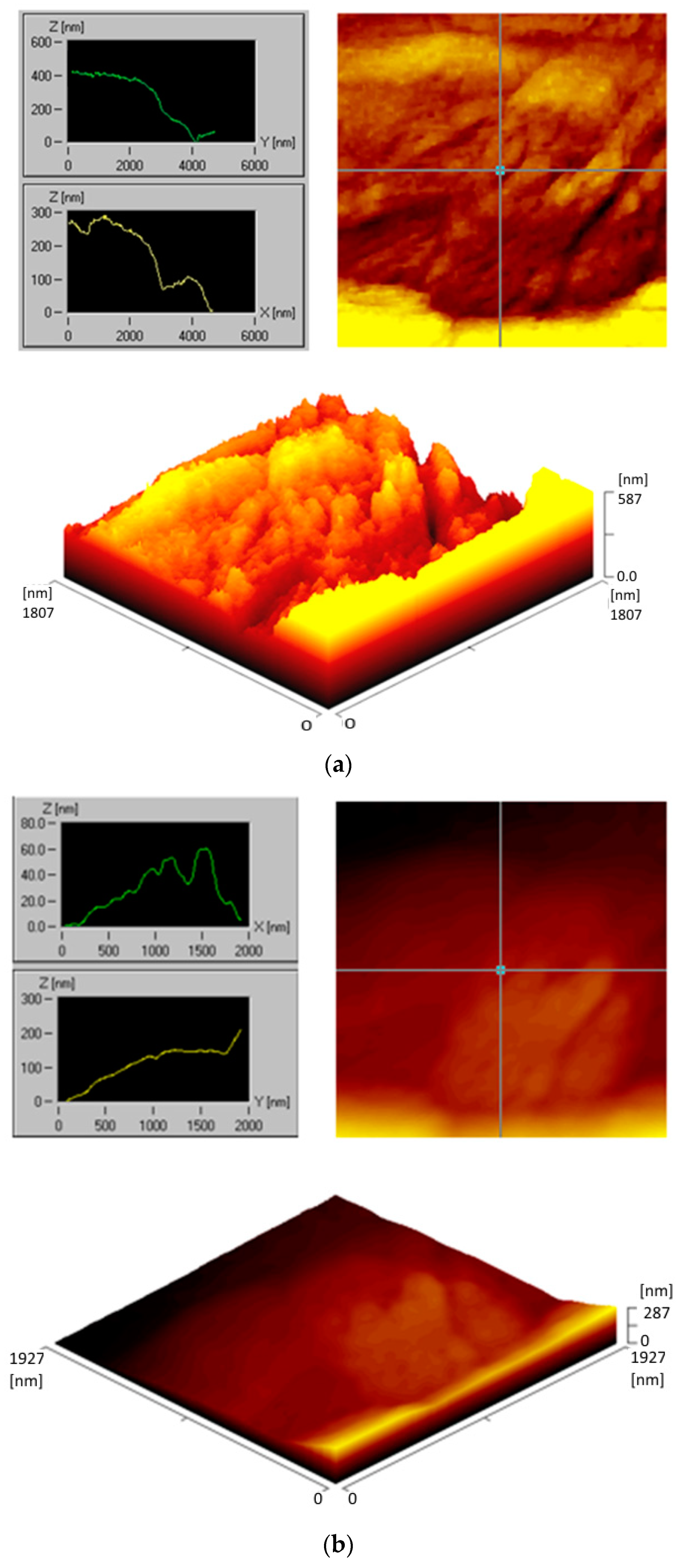
Figure 17 presents the surface microgeometry of the ball joints utilized in a Nissan Maxima (mileage: 150,000 km, vehicle age: 9 years). This car did not pass the technical inspection at the diagnostic station due to the poor condition of the control arms ball joints. In both cases, material losses were visible. It might be caused by the ripped rubber covers, which resulted in leakage of water and other impurities into the joint interior and, finally, damage.
The surface microgeometry of the ball joint bearings for a Peugeot 206, Mercedes Sprinter, and Nissan Maxima varied from 0.16 to 0.40 μm, which was distributed on the entire surface. The microgeometry measurements and the observation showed that the low and high values of the Ra parameter occurred in close vicinities with respect to each other, without a clear tendency to form in a specific location or to create a pattern. In addition, no such tendencies were observed in the form of surface abrasions. The absence of contamination, low loads, and proper temperature values allow for abrasion with low values of the Ra parameter to occur in specific locations. Such a case can happen when the bearing is subjected to forces acting in one direction with a constant or repeatable manner. A surface wear pattern can be in a form of parallel microgrooves, along with characteristic roughness parameter variation. It may form under varying load conditions, but the relative movement of the mating surfaces must be of a repetitive nature. The lack of such tendencies may indicate many factors influencing the bearing surface wear process, such as abrasive wear, deformation, the effect of impurities, etc.
Steel pins STM microscope examination and measurements of bearings made of POM or PEEK with a PTFE layer using a profilometer were conducted after a certain number of cycles, which corresponds to a specific mileage (from 30,000 to 115,000 km). Interestingly, the greatest decrease in roughness parameter Ra was observed for the cases of mileage between 80,000 and 90,000 km. Assuming that it was strongly affected by the wear process of the mating surfaces, the authors suppose that the most intense utilization of the factory-mounted ball joints appeared between 80,000 and 90,000 km of mileage.

3.2. Experimental Determination of Material Model Parameters

The obtained value of displacement u u n l o a d e d 0 was equal to 6.00 ± 0.01 mm and the value of the displacement u u n l o a d e d was equal to 6.01 ± 0.01 mm. Due to an insignificant difference between those displacements, it was omitted in further analysis. The obtained values of u l o a d e d with respect to loading force F are presented in Table 1. Values of displacement u X were calculated using Equation (1).

3.3. Numerical Determination of Ball Joint Bearing Deformations

Figure 18 presents the displacements along the X axis, which were produced by the tilt arm being loaded by force F of 30 N, being in contact with the material sample. The related displacement of the cylindrical surface c of bearing needle (8) (Figure 7) was below 0.9 mm.
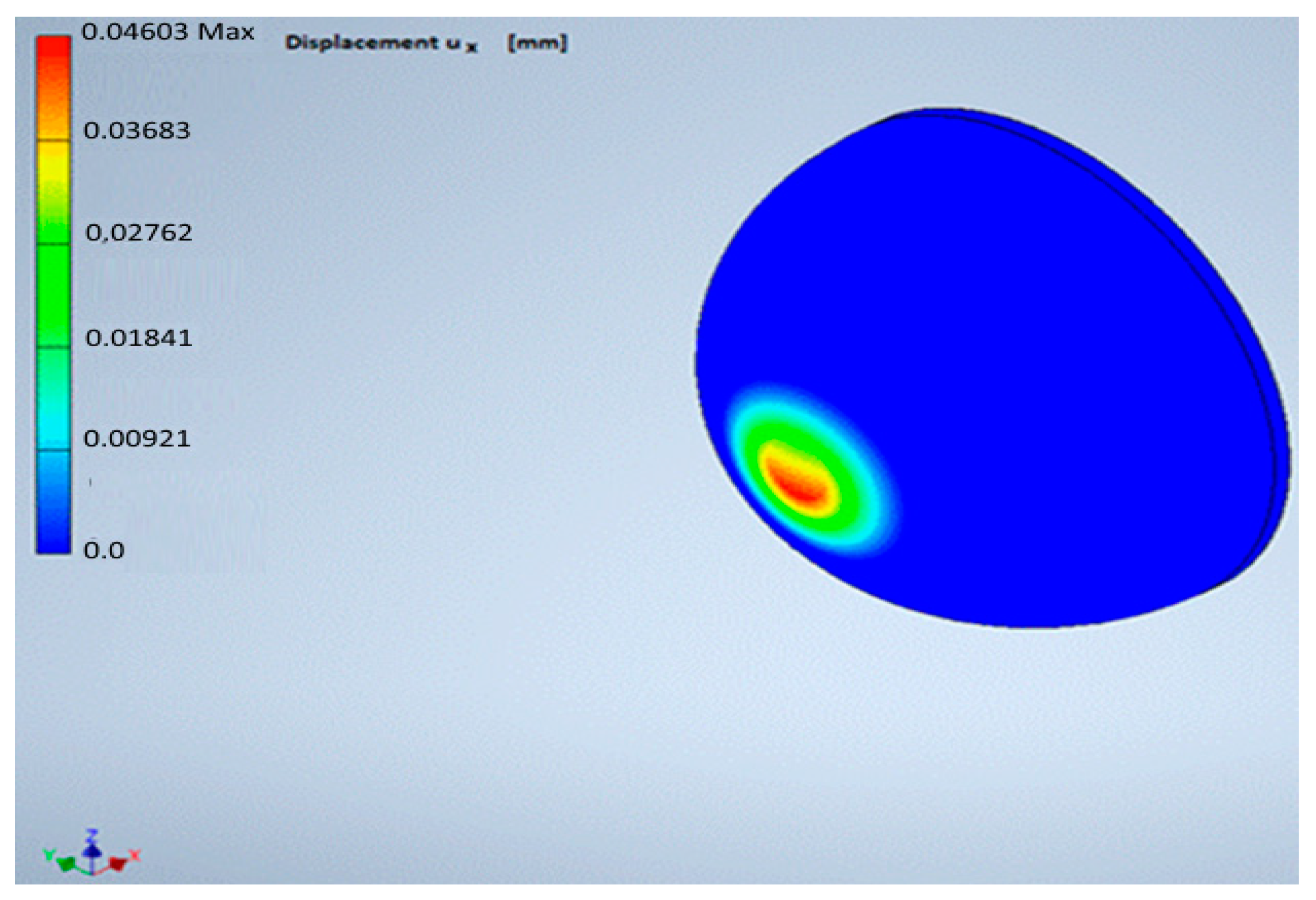
Such displacements along the X axis for the upper surface of the tested material sample were presented in Figure 19. Their values were below 0.046 mm.
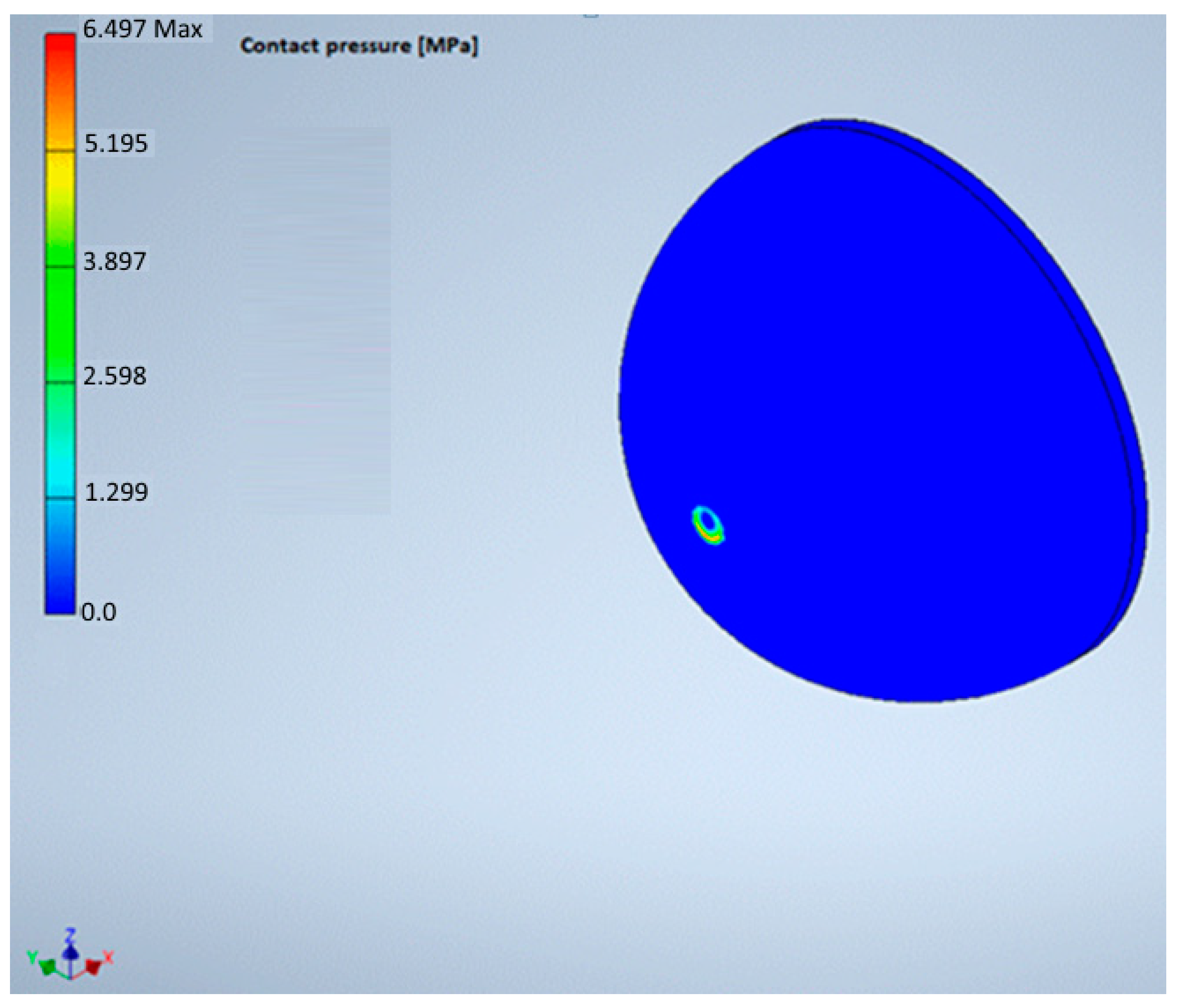
The contact pressure between the tilt arm and the tested material sample is presented in Figure 20. Its values were below 6.5 MPa. Assuming the linear material model of ball joint bearing, for the loading force F value equal to 10 N, the contact pressure values were below 2 MPa.
The resulting displacement u X is listed in Table 2. It is clear that the Poisson ratio had a much smaller effect then the Young modulus of the bearing material on the displacement u X .
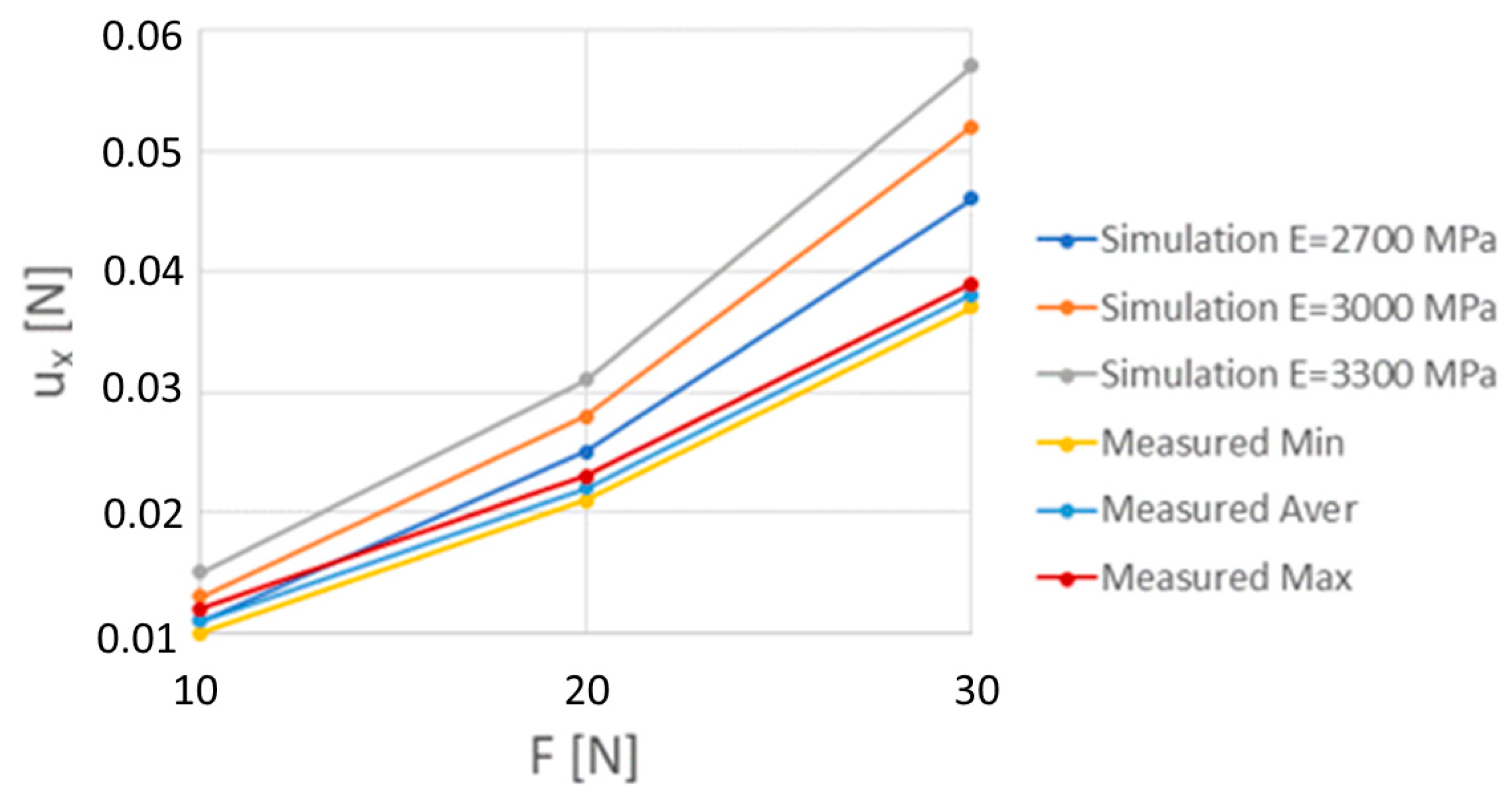
Figure 21 presents the value of displacement u X as a function of force F, obtained both from measurements and simulations. For the Young modulus values in the range 2700–3000 MPa, and especially for smaller values of force F below 10 N, the values of displacement u X obtained from simulations were in a good agreement with those obtained from measurement. Therefore, it was assumed that the material model of the control arm ball joint bearing was characterized by the Young modulus of 3000 MPa and the Poisson number equal to 0.4.

3.4. Determination of Friction Coefficient between Steel and Ball Joint Bearing Material

Table 3 presents the friction coefficient values of ball joint bearings and steel balls, with and without lubrication. The friction coefficients for unlubricated conditions were twice as high as for those with a thin layer of lithium grease. Moreover, the values of the friction coefficient with lubrication were almost twice higher than those suggested in [42]. The operational conditions in this case could greatly differ due to different humidity, temperature, contact profile, and loads. Additionally, results of the frictional test described in this paper were obtained using a different approach than that in [42]. In particular, the test done by the authors was conducted with uniformly accelerated translational motion, with the possibility of a stick–slip phenomenon. The other team was not only using vibrational motion, but the tests were conducted at room temperature instead of 50 °C. In addition, the load differed from the usual 2000 N. Both the presence of vibrations, high load, and elevated temperature may have favored a reduction in the coefficient of friction under grease lubrication conditions but without fully developed fluid friction. Therefore, the obtained values of friction force should be recognized as coarse estimation.

3.5. Calculation Results of the Resistive Force and Torque in Ball Joint

An obtained distribution of contact pressure p i n t e r between the ball joint pin and its bearing is shown in Figure 22a. Its value was approximately 1.2 MPa. The corresponding von Mises stress distribution is shown in Figure 22b and corresponding displacements are shown in Figure 22c. The obtained values of the von Mises stress were below 0.62 MPa and those of displacements were below 1.2 μm.
The value of the total resistive torque M r e s i s t generated during interference between the steel ball and POM bearing estimated from Equation (2) was equal to 7.13 Nm. In [43], it was reported that resistive torque can reach values below 3.5 Nm. However, for the friction coefficient value of 0.8, the torque M r e s i s t is equal to 4.75 Nm. Considering the presence of grease in the contact zone, this torque may be even closer to the value specified in [43]. However, with the development of the lubricant wear process, the values of such a torque increase.
An exemplary distribution of von Mises stress obtained for contact between the PTFE hemisphere and steel hemisphere is shown in Figure 23a. The PTFE hemisphere was displaced by 0.4 μm in the X direction against a fixed steel hemisphere. This was illustrated by Figure 23b presenting the displacement in the X direction relative to time for the peak node of PTFE hemisphere. Obtained values of von Mises stress corresponding to the PTFE hemisphere displacement of 0.2 μm in the X direction were below 105 MPa. Displacement in the Y direction relative to time for the peak node of the PTFE hemisphere is presented in Figure 23c. The maximum value of such displacement in the Y direction was 0.056 μm.
An exemplary distribution of contact pressures between the PTFE hemisphere or spherical cap and the face of the rigid cylinder is presented below. Figure 24a shows the case of hemisphere and Figure 24b shows the sphere section. Having the rigid cylinder displacement of 0.05 μm in the Y direction, the contact pressure in case of hemisphere was below 193 MPa, and in case of a spherical cap, it was below 117 MPa—so the yield strength was reached in the entire contact zone.
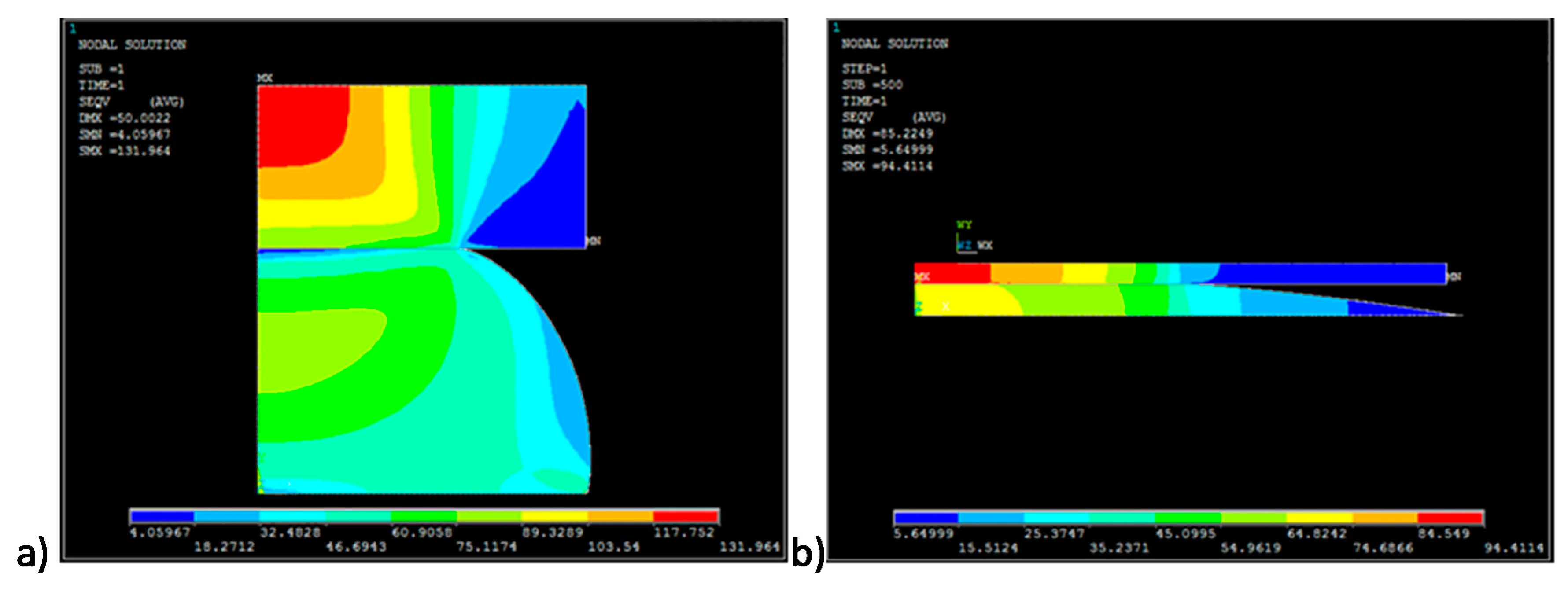
The corresponding distribution of von Mises stress is shown in Figure 25a for the case of hemisphere and in Figure 25b for the case of spherical cap. Obtained von Mises stress values were below 132 MPa for the hemisphere and below 95 MPa for the spherical cap.
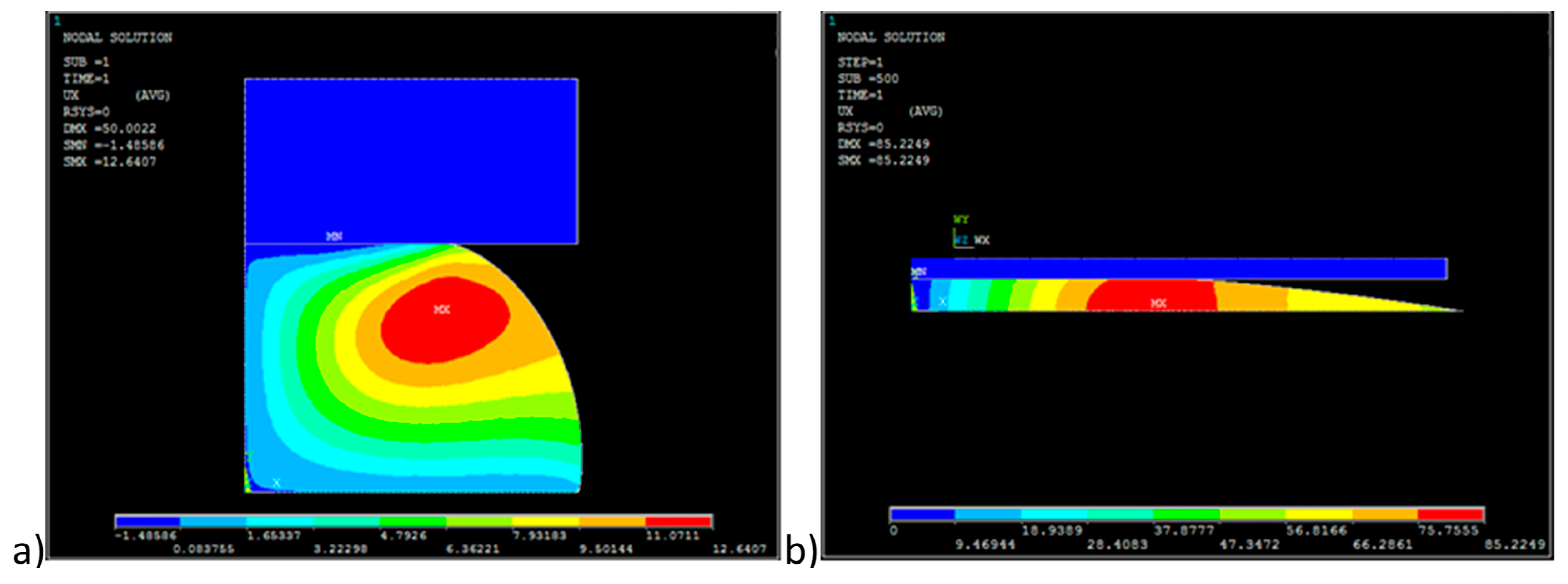
The corresponding displacements in the horizontal direction are shown in Figure 26a for the case of hemisphere and in Figure 26b for the case of spherical cap. Obtained values of the displacement in the horizontal direction were below 0.013 μm for the hemisphere and below 0.086 μm for the spherical cap.
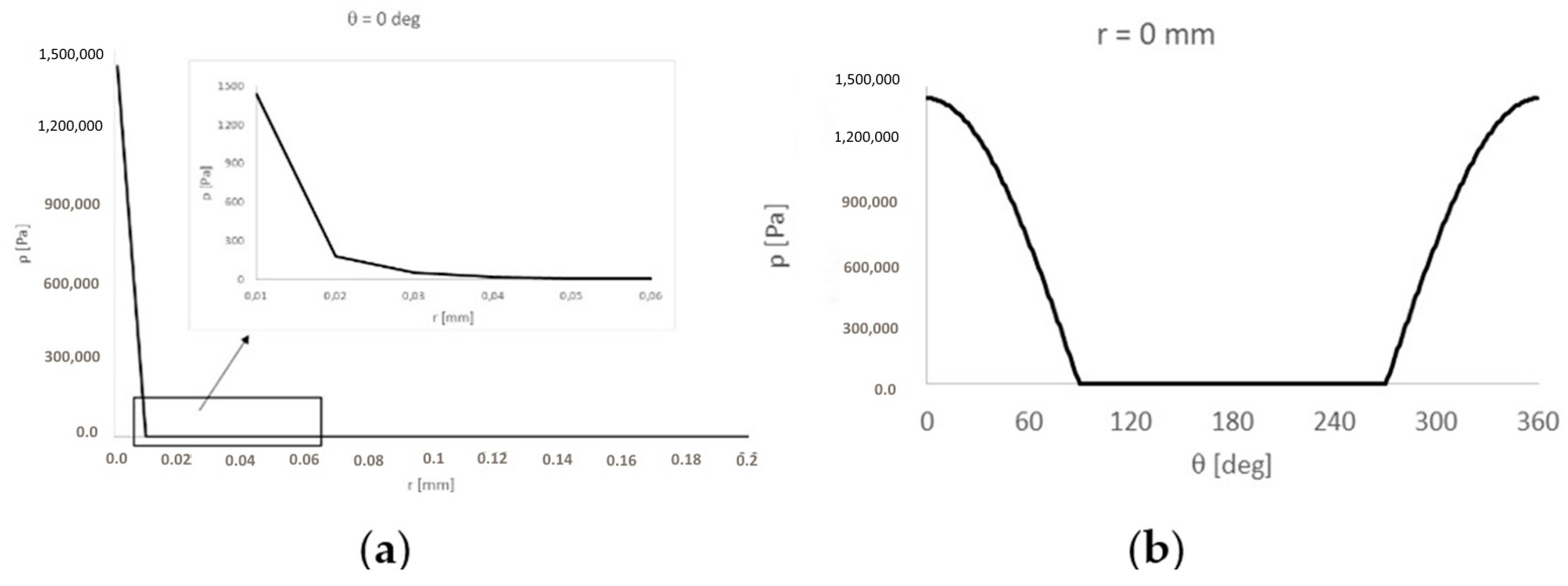
The hydrodynamic pressure p(r, θ) functions are presented below. Figure 27a shows the function in relation to radius r of the hemisphere projection on mating plane (θ = 0 deg), and Figure 27b presents this function in relation to angle θ (r = 0 mm). Obtained values of hydrodynamic pressure were below 1.5 MPa. The value of such pressure averaged over the area of projection of the hemisphere on the mating plane was about 0.85 MPa. Such value can be assumed as close to one of pressure p i n t e r in Equation (13).
The value of the work done during the deformation of mating bodies obtained from the finite element model was equal to 76 × 10−13 mJ. For an average displacement Δ x = 0.2 μm of PTFE hemisphere against the steel hemisphere in the X direction, the resistive force F d e f o r m estimated from Equation (7) was equal to 38 μN. The number n of modeled hemispheres estimated from Equation (8) was equal to 6,259,148. Therefore, the value of the resistive torque Mdeform estimated from Equation (9) was equal to 2.72 Nm.
The finite element model allowed obtaining the radius rreal of contact between the rigid sphere surface and PTFE hemisphere. It was equal to approximately 0.13 μm. For the contact between the rigid sphere surface and PTFE spherical cap, radius rreal was equal to about 1 μm. The resistive force F a d h e s i o n estimated from Equation (10) was equal to 2.56 μN for the PTFE hemisphere model and 157 μN for the PTFE spherical cap model. This is 61 times higher than in the case of polyoxymethylene hemisphere. The value of the resistive torque Madhesion estimated from Equation (11) was equal to 168 Nm for the PTFE hemisphere model and 10.6 Nm for the PTFE spherical cap model. The values of resistive force F a d h e s i o n and the resistive torque Madhesion vary depending on the choice of contact model.
For the angular speed ω of rotating ball equal to 1 rad/s, the resistive force F f l u i d estimated from Equations (14) and (15) was equal to 0.0256 μN for the pressure p i n t e r = 1.2 MPa that was estimated using FEA. For value of p i n t e r = 0.85 MPa, the resistive force F f l u i d value was of 0.0206 μN, which was very close to that from the case of the pressure p i n t e r = 1.2 MPa.
The resistive torque Mfluid estimated from Equation (16) was equal to 1.2 Nm.
The total resistive torque M values generated at low value or even lack of interference between the steel ball and the PTFE layer of the bearing were below 2.88 Nm for the case of hemisphere and below 13.32 Nm for the case of a spherical cup used for modeling of the asperity shape.
In the case of the hemisphere model of asperity, the total resistive torque M reached values three times lower than the torque M r e s i s t . In case of a spherical cup model of asperity, the total resistive torque M reached values 1.87 times higher than the torque M r e s i s t . Such high values of the total resistive torque M are also higher by 30% from these of the breakaway torque reported in [43].

4. Conclusions

Two simple testers are described in this paper: one for determining the material parameters of the control arm ball joint bearing and the other for determination of the friction coefficient between the steel plate and bearing sample. The simple linear material model for the mentioned bearing was based on finite element analysis. The material model was characterized by the equivalent Young modulus and the equivalent Poisson ratio. Such a model allowed determination of the displacement values u X in a control location, which were in agreement with those obtained from measurements conducted using such a tester. It was clearly seen for the Young modulus values in the range of 2700–3000 MPa and for small values of loading force F below 10 N. Therefore, the choice of the material model parameters such as the Young modulus of 3000 MPa and Poisson number equal to 0.4 was acceptable.
The values of the resistance to motion for contact between steel and the material of the ball joint bearing estimated in the elaborated tester were at least twice higher than those reported in the standard [42] recommended for grease lubricated plastic socket suspension joints, which was due to the different conditions of tests conducted.
It may be concluded that within the range between 80,000 and 90,000 km of mileage, wear appears on the mating surfaces of the ball joints, and it is highly recommended to verify the components and possibly replace them with new ones. The ball joints bought on the secondary market may endure only a 3-year utilization.
The calculated values of the total resistive torque M r e s i s t generated during the interference between a steel ball and POM bearing are higher than those reported in [42] for a similar ball joint. However, for the lower values of the resistance to motion for contact between a steel ball and bearing made of POM with PTFE [33], as well as enough grease, calculated values of the torque M r e s i s t can be much closer to those given in [43].
When interference between a steel ball and POM bearing decreases due to the wear process between mating surfaces and grease, the total resistive torque M generated during the rotation of a ball joint pin against its bearing depends mainly on the resistive moment Mdeform generated due to the deformations of mating bodies. It depends much less on the resistive torque Madhesion generated due to adhesion and on the resistive torque Mfluid generated due fluid shear stresses. The latter influences the torque M only in a very small extent and can be omitted. However, both the Madhesion and the Mfluid depend on the choice of the contact model.

Author Contributions

Conceptualization, K.S. and M.W.; methodology, M.W.; software, P.K.; validation, G.O., K.S.; formal analysis, M.W.; investigation, M.W. and K.S.; resources, P.K., M.W.; data curation, M.W.; writing—original draft preparation, K.S.; writing—review and editing, G.O.; visualization, P.K. All authors have read and agreed to the published version of the manuscript.

Funding

This research received no external funding.

Conflicts of Interest

The authors declare no conflict of interest.

References

  1. Wozniak, M.; Ozuna, G.; De La Fuente, P.; Jozwiak, P.; Pawelski, Z. Test bench with AFM and STM modules for wear researches passenger’s car suspensions elements. Int. Virtual J. Sci. Tech. Innov. Ind. MTM 2012, 4, 9–11. [Google Scholar]
  2. Patil, P.B.; Kharade, M.V. Finite Element Analysis and Experimental Validation of Lower Control Arm. Int. J. Eng. Dev. Res. 2016, 4, 1914–1922. [Google Scholar]
  3. Duffy, J.E. Modern Automotive Technology, 9th ed.; The Goodheart-Willcox Company: Tinley Park, IL, USA, 2017. [Google Scholar]
  4. Mondragon-Parra, E.; Ambrose, G. Influence of Grease in Mechanical Efficiency of Constant Velocity Joints; SAE Technical Paper; SAE International: Warrendale, PA, USA, 2016. [Google Scholar]
  5. Yao, J.; Wang, M.; Li, Z.; Jia, Y. Research on Model Predictive Control for Automobile Active Tilt Based on Active Suspension. Energies 2021, 14, 671. [Google Scholar] [CrossRef]
  6. Heißing, B.; Ersoy, M. Chapter 5. Ride Comfort and NVH. In Chassis Handbook; Heißing, B., Ersoy, M., Eds.; Vieweg + Teubner: Wiesbaden, Germany, 2011; pp. 421–448. [Google Scholar]
  7. Paulraj, M.P.; Yaacob, S.; Andrew, A.M. Vehicle noise comfort level indication: A psychoacoustic approach. In Proceedings of the 6th International Colloquium on Signal Processing & its Applications, Mallaca City, Malaysia, 21–23 May 2010; pp. 1–5. [Google Scholar]
  8. Chung, S.S.; Lee, Y.Z.; Park, S.O. Practical Evaluation of Ball Stud Plating Effects on the Increase of Free Gap of Ball Joints in the Vehicle. Int. J. Automot. Technol. 2020, 21, 1107–1111. [Google Scholar] [CrossRef]
  9. Wozniak, M.; Ozuna, G.; De La Fuente, P.; Jozwiak, P.; Pawelski, Z. Comparision of friction coefficient for selected car suspension elements. Int. Virtual J. Sci. Tech. Innov. Ind. MTM 2014, 4, 23–25. [Google Scholar]
  10. Kang, J. Theoretical model of ball joint squeak. J. Sound Vib. 2011, 330, 5490–5499. [Google Scholar] [CrossRef]
  11. Farfan-Cabrera, L.I. Tribology of electric vehicles: A review of critical components, current state and future improvement trends. Tribol. Int. 2019, 138, 473–486. [Google Scholar] [CrossRef]
  12. Zhang, J.; Wang, D.; Chen, W. The application of PTFE coating on spherical joints. In Proceedings of the 2nd International Conference on Machinery, Materials Engineering, Chemical Engineering and Biotechnology, Chongqing, China, 28–29 November 2015. [Google Scholar]
  13. Komori, K.; Nagataki, T. Friction behavior of diamond-like carbon coated ball joint: Approach to improving vehicle handling and ride-comfort. SAE Int. J. Passeng. Cars-Mech. Syst. 2015, 8, 638–646. [Google Scholar] [CrossRef]
  14. Palange, N. Common Problems with Control Arm Bushings and How to Prevent Them. V&FAuto. 23 January 2018. Available online: https://vfauto.com/common-problems-control-arm-bushings-fix/ (accessed on 3 October 2020).
  15. Ossa, E.A.; Palacio, C.C.; Paniagua, M.A. Failure analysis of a car suspension system ball joint. Eng. Fail. Anal. 2011, 18, 1388–1394. [Google Scholar] [CrossRef]
  16. Symptoms of a Bad or Failing Ball Joint (Front). 2016. Available online: https://www.autoblog.com/2016/01/04/symptoms-of-a-bad-or-failing-ball-joint-front/ (accessed on 3 October 2020).
  17. Omar, S.B. Tribology study of suspension and linkages in automotive. Mytribos Symp. 2017, 2, 38–40. [Google Scholar]
  18. Muscă, I.; Românu, I.C.; Gagea, A. Preliminary study of friction in automotive ball joints. In Proceedings of the IOP Conference Series: Materials Science and Engineering, Proceedings of the International Conference on Tribology (ROTRIB’19), Cluj-Napoca, Romania, 19–21 September 2019; Volume 724. [Google Scholar]
  19. Watrin, J.-C.; Makich, H.; Haddag, B.; Nouari, M.; Grandjean, X. 23ème Congrès Français de M 23ème Congrès Français de Mécanique [CFM2017 Analytical modelling of the ball pin and plastic socket contact in a ball joint. In Proceedings of the Conference Proceedings, Lille, France, 28 August–1 September 2017. [Google Scholar]
  20. Sahu, D.P.; Singh, M.K.; Singh, S.; Sahu, N.K. Dynamics Analysis of Frictionless Spherical Joint with Flexible Socket. In Innovative Product Design and Intelligent Manufacturing Systems. Lecture Notes in Mechanical Engineering; Deepak, B., Parhi, D., Jena, P., Eds.; Springer: Singapore, 2020. [Google Scholar]
  21. Sin, B.-S.; Lee, K.-H. Process Design of a Ball Joint, Considering Caulking and Pull-Out Strength. Sci. World J. 2014, 2014, 971679. [Google Scholar] [CrossRef]
  22. Sun, Z.; Hao, C. Conformal Contact Problems of Ball-socket and Ball. Phys. Procedia 2012, 25, 209–214. [Google Scholar] [CrossRef] [Green Version]
  23. Koumura, S.; Shionoya, T. Ride comfort analysis considering suspension friction with series rigidity. SAE Int. J. Passeng. Cars-Mech. Syst. 2016, 9, 409–418. [Google Scholar] [CrossRef]
  24. Rutci, A.; Eren, S. Investigation of Suspension Ball Joint Pull Out Force Based on FEA Method and Experimental Study. In Proceedings of the 6th International Symposium on Innovative Technologies in Engineering and Science, Alanya, Turkey, 9–11 November 2018. [Google Scholar]
  25. Yang, X. Effects of bushings characteristics on suspension ball joint travels. Veh. Syst. Dyn. 2011, 49, 181–197. [Google Scholar] [CrossRef]
  26. Burcham, M.N.; Escobar, R.; Yenusah, C.O.; Stone, T.W.; Berry, G.N.; Schemmel, A.L.; Watson, B.M.; Verzwyvelt, C.U. Characterization and Failure Analysis of an Automotive Ball Joint. J. Fail. Anal. Prev. 2017, 17, 262–274. [Google Scholar] [CrossRef]
  27. Dowson, D.; Wang, D. Impact elastohydrodynamics. In Tribology Series; Dowson, D., Taylor, C.M., Childs, T.H.C., Dalmaz, G., Eds.; Elsevier: Amsterdam, The Netherlands, 1995; Volume 30, pp. 565–582. [Google Scholar]
  28. Raj, V. Analysis of Ball Stud Plating Effects on Variations of Vacuum Gap of Ball Joints in the Automobile. Int. Res. J. Mod. Eng. Technol. Sci. 2020, 2, 3694474. [Google Scholar]
  29. Park, K.D.; Ryu, H.J. A study on corrosion characteristics of suspension material by surface processing. Trans. Korean Soc. Automot. Eng. 2005, 13, 17–23. [Google Scholar]
  30. Trapp, M.; Chen, F. Automotive Buzz, Squeak and Rattle, 1st ed.; Elsevier: Waltham, MA, USA, 2012. [Google Scholar]
  31. Marques, F.; Flores, P.; Claro, J.C.; Lankarani, H. Modeling and analysis of friction including rolling effects in multibody dynamics: A review. Multibody Syst. Dyn. 2018, 45, 223–244. [Google Scholar] [CrossRef]
  32. ASTM D7420—11: Standard Test Method for Determining Tribomechanical Properties of Grease Lubricated Plastic Socket Suspension Joints Using a High-Frequency, Linear-Oscillation (SRV) Test Machine; ASTM International: West Conshohocken, PA, USA, 2011.
  33. Weiss, C.; Morlock, M.M.; Hoffmann, N.P. Friction induced dynamics of ball joints: Instability and post bifurcation behavior. Eur. J. Mech. A Solids 2014, 45, 161–173. [Google Scholar] [CrossRef]
  34. High Performance Polymers. Available online: https://www.tribology-abc.com/abc/polymers.htm (accessed on 3 October 2020).
  35. Habel, O. Instationäre Mischreibungssimulation Konformer Stahl-Polymer-Kontakte unter Berücksichtigung von Mangelschmierungseffekten. Ph.D. Thesis, Ruhr-Universität Bochum, Bochum, Germany, 2013. [Google Scholar]
  36. Geren, N.; Osman, O.A.; Melih, B. Parametric design of automotive ball joint based on variable design methodology using knowledge and feature-based computer assisted 3D modelling. Eng. Appl. Artif. Intell. 2017, 66, 87–103. [Google Scholar] [CrossRef]
  37. Ansys v.19.3 Mechanical APDL Documentation. Available online: https://ansyshelp.ansys.com/account/secured?returnurl=/Views/Secured/corp/v193/ans_mat/amp8sq21dldm.html%23elemedp (accessed on 3 October 2020).
  38. Frédy, C. Modeling of the Mechanical Behavior of Polytetrafluoroethylene (PTFE) Compounds during Their Compaction at Room Temperature. Ph.D. Thesis, Université Pierre et Marie Curie, Paris, France, 2015. [Google Scholar]
  39. Clarhed, D. Stress Analysis of PTFE Sleeves in Industrial Valves; Lund University: Lund, Sweden, 2008. [Google Scholar]
  40. Bergstrom, J. Accurate Finite Element Simulations of PTFE Components; Veryst Engineering, LLC: Needham, MA, USA, 2012. [Google Scholar]
  41. Löfgrena, H.B. A solution to the hydrodynamic lubrication of a circular point contact sliding over a flat surface with cavitation. Theor. Appl. Mech. Lett. 2012, 2, 032004. [Google Scholar] [CrossRef] [Green Version]
  42. Woydt, M.; Schneider, A. Application oriented tribological test concepts. Lube Mag. 2020, 159, 22–28. [Google Scholar]
  43. Heißing, B.; Ersoy, M. Chassis Handbook. Fundamentals, Driving Dynamics, Components, Mechatronics, Perspectives; ATZ/MTZ-Fachbuch Series; Heißing, B., Ersoy, M., Eds.; Vieweg + Teubner Verlag, Springer: Berlin/Heidelberg, Germany, 2011. [Google Scholar]
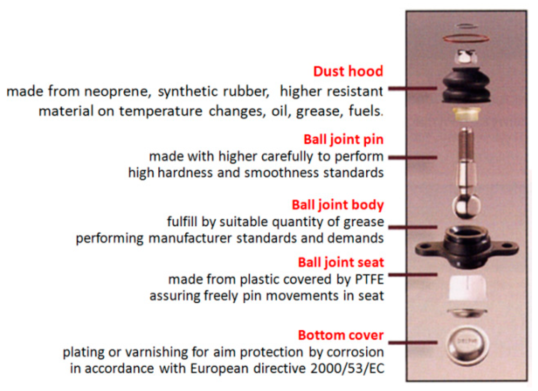
Figure 1. Components of a ball joint [8].
Energies 14 03238 g001
Figure 2. The most often defects of the ball joints: (a) Ripped rubber cover; (b) Frozen ball joint; (c) Corrosion of a mandrel.
Energies 14 03238 g002
Figure 3. (a) New ball joint; (b) Disassembled used ball joint.
Energies 14 03238 g003
Figure 4. Points 1–8 showing roughness measurement points on the spherical surface of a ball joint.
Energies 14 03238 g004
Figure 5. Prepared samples of POM and PEEK bearing of analyzed ball joints.
Energies 14 03238 g005
Figure 6. Scheme of a measuring unit for determination of the Young modulus of ball joint bearing; (a) During determining the initial position of the screw with fine thread isolated relatively to the support relatively to the latter; (b) During measurement of deformation of the polymer-bearing material sample tested. 1—support, 2—tilt arm, 3—pin (needle bearing shaft), 4—bearing needle, 5—needle, 6—pin of hoop of a loading unit assembly with weights, 7—bearing needle, 8—cord of hoop of a loading unit assembly with weights, 9—pin of hoop connected to the string of the weights’ holder, 10—nut isolated relatively to the support, 11—screw with fine thread isolated relatively to the support, 12—aligning bearing roller, 13—tested bearing material sample, 14—battery, 15—control light, 16—depth gauge micrometer, 17—seat in the support for positioning of tested bearing material sample, 18—seat in the support for positioning of depth gauge micrometer, F—loading force from weights, A—detailed view.
Energies 14 03238 g006
Figure 7. Scheme of numerical model of selected mating components of the measuring unit for determination of the Young modulus of polymer bearing. 1—support fragment, 2—tilt arm, 3—tested bearing material sample, 4—cylindrical tip of the screw with fine thread, 5—bearing needle, 6—surface of tilt arm hole for the needle bearing placement, 7—pin of hoop of a loading unit assembly with weights, 8—bearing needle, a—fixed force of cylindrical tip of a screw, b—cylindrical surface of pin loaded by the force F from weights, c—cylindrical surface of the bearing needle whose displacements along the X-axis are compared with measured values.
Energies 14 03238 g007
Figure 8. The mesh of finite elements.
Energies 14 03238 g008
Figure 9. Tester for friction coefficient determination between steel plane and ball joint bearing sample, (a) for the contact between a spherical surface of sample 10 with tilting plane 2; (b) for the contact between a frontal plane of sample 10 with tilting plane 2.
Energies 14 03238 g009
Figure 10. (a) Model of contact between ball joint pin 1 and its bearing 2; (b) the mesh of finite elements and boundary conditions.
Energies 14 03238 g010
Figure 11. (a) Model composed of fixed hemisphere made of steel and of moving hemisphere made of polyoxymethylene; (b) Mesh of finite elements and boundary conditions.
Energies 14 03238 g011
Figure 12. (a) Model composed of polyoxymethylene hemisphere 1 mated with moving rigid cylinder 2; (b) Mesh of finite elements and boundary conditions.
Energies 14 03238 g012
Figure 13. (a) Model composed of polyoxymethylene spherical cap 1 mated with moving rigid cylinder 2; (b) Mesh of finite elements and boundary conditions.
Energies 14 03238 g013
Figure 14. (a) Model of plane (1) moving against fixed hemisphere with the speed V. Volume (3) between hemisphere and its projection (4) is filled with lithium grease; (b) The polar coordinate system for calculation of hydrodynamic pressure in the volume (3).
Energies 14 03238 g014
Figure 15. Ra profile on the spherical surfaces of ball joints for Peugeot 206: (a) Manufacturer ball joint, mileage: below 30,000 km, vehicle age: 1 year; (b) Replacement part ball joint, mileage: 40,000 km, vehicle age: 3.5 years; (c) Manufacturer ball joint, mileage: 115,000 km, vehicle age: 8 years; (d) Manufacturer ball joint, mileage: 90,000 km, vehicle age: 7 years.
Energies 14 03238 g015aEnergies 14 03238 g015b
Figure 16. Ra profile on the spherical surfaces of ball joints for a Mercedes Sprinter (mileage: 80,000 km, vehicle age: 6 years): (a) Manufacturer ball joint, right side; (b) Manufacturer ball joint, left side.
Energies 14 03238 g016
Figure 17. Ra profile on the spherical surfaces of ball joints for Nissan Maxima: (a) Right side; (b) Left side.
Energies 14 03238 g017
Figure 18. Tilt arm displacements along the X axis when loaded with 30 N and in contact with the material sample.
Energies 14 03238 g018
Figure 19. The displacements along the X axis for the upper surface of the tested material sample.
Energies 14 03238 g019
Figure 20. The contact pressure between the tilt arm and the tested material sample.
Energies 14 03238 g020
Figure 21. Displacement u X as a function of force F obtained from simulations and measurements.
Energies 14 03238 g021
Figure 22. (a) Distribution of contact pressure p i n t e r between the ball joint pin and its bearing; (b) Corresponding Mises stresses; (c) Corresponding displacements.
Energies 14 03238 g022
Figure 23. (a) Distribution of von Mises stress for contact between PTFE hemisphere and steel hemisphere; (b) Course of displacement in the X direction against time for the peak node of polyoxymethylene hemisphere; (c) Course of displacement in the X direction against time for the mentioned peak node.
Energies 14 03238 g023
Figure 24. Exemplary distribution of contact pressures between the face of the rigid cylinder and the polyoxymethylene: (a) Hemisphere; (b) Spherical cap.
Energies 14 03238 g024
Figure 25. Exemplary distribution of von Mises stress for the contact between the face of the rigid cylinder and the PTFE: (a) Hemisphere; (b) Spherical cap.
Energies 14 03238 g025
Figure 26. Exemplary distribution displacements in the horizontal direction for the contact between the face of the rigid cylinder and the PTFE: (a) Hemisphere; (b) Spherical cap.
Energies 14 03238 g026
Figure 27. (a) Course of hydrodynamic pressure p(r, θ) versus radius r of projection of the hemisphere on mating plane, for θ = 0 deg; (b) Course of hydrodynamic pressure p(r, θ) versus angle θ for r = 0 mm.
Energies 14 03238 g027
Table 1. Measured displacement u l o a d e d and force F, and calculated displacement u X .
Force F [N]Displacement
u l o a d e d [mm]
Displacement
u X [mm]
106.22 ± 0.010.011 ± 0.001
206.48 ± 0.010.022 ± 0.001
306.81 ± 0.010.038 ± 0.001
Table 2. Values of Young modulus E, the Poisson ratio ν, and displacement u X obtained from simulations for various values of the loading force F.
Force F [N]Young Modulus E [MPa]Poisson Number ν [-]Displacement u X [mm]
1027000.30.009
0.40.011
30000.30.011
0.40.013
33000.30.013
0.40.015
2027000.30.021
0.40.023
30000.30.024
0.40.026
33000.30.026
0.40.028
3027000.30.044
0.40.046
30000.30.050
0.40.052
33000.30.055
0.40.057
Table 3. Measured values of tilt angle α and the related friction coefficient μ in contact between steel and material of ball joint bearing, both unlubricated and lubricated by lithium grease.
Lubrication ConditionsTilt Angle α [deg]Friction Coefficient μ [-]
Lack of lubricant10–140.176–0.249
Lubrication by lithium grease5–70.087–0.122
Publisher’s Note: MDPI stays neutral with regard to jurisdictional claims in published maps and institutional affiliations.