
A Study of Low-Potential Heat Utilization Methods for Oxy-Fuel Combustion Power Cycles


Abstract
:1. Introduction
2. Research Objectives
3. Methodology
- The temperature difference in the pinch point was below 5 °C.
- The turbine cooling agent’s temperature was 200 °C.
- The minimal compressed air temperature at the exit of the regenerator was 30 °C.
- The temperatures of all the heated flows, except that of the cooling agent flow at the regenerator exit, were equal.
4. Results and Discussion
5. Conclusions
Author Contributions
Funding
Institutional Review Board Statement
Informed Consent Statement
Data Availability Statement
Conflicts of Interest
References
- Mauleon, I. Economic Issues in Deep Low-Carbon Energy Systems. Energies 2020, 13, 4151. [Google Scholar] [CrossRef]
- Eitan, A.; Rosen, G.; Herman, L.; Fishhendler, I. Renewable Energy Entrepreneurs: A Conceptual Framework. Energies 2020, 13, 2554. [Google Scholar] [CrossRef]
- Climent Barba, F.; Sanchez, G.M.D.; Segui, B.S.; Darabkhani, H.G.; Anthony, E.J. A Technical Evaluation, Performance Analysis and Risk Assessment of Multiple Novel Oxy-Turbine Power Cycles with Complete CO2 Capture. J. Clean. Prod. 2016, 133, 971–985. [Google Scholar] [CrossRef]
- Hamadeh, H.; Toor, S.Y.; Douglas, P.L.; Sarathy, S.M.; Dibble, R.W.; Croiset, E. Techno-Economic Analysis of Pressurized Oxy-Fuel Combustion of Petroleum Coke. Energies 2020, 13, 3463. [Google Scholar] [CrossRef]
- Rogalev, A.; Kindra, V.; Osipov, S.; Rogalev, N. Thermodynamic Analysis of the Net Power Oxy-Combustion Cycle. In Proceedings of the 13-th European Conference on Turbomachinery Fluid dynamics & Thermodynamics, Lausanne, Switzerland, 8–12 April 2019. [Google Scholar]
- Yang, H.J.; Kang, D.W.; Ahn, J.H.; Kim, T.S. Evaluation of Design Performance of the Semi-Closed Oxy-Fuel Combustion Combined Cycle. J. Eng. Gas Turb. Power 2012, 134, 111702. [Google Scholar] [CrossRef]
- Rogalev, A.; Kindra, V.; Zonov, A.; Rogalev, N.; Agamirov, L. Evaluation of Bleed Flow Precooling Influence on the Efficiency of the E-MATIANT Cycle. Mech. Mech. Eng. 2018, 22, 593–602. [Google Scholar] [CrossRef]
- Allam, R.; Martin, S.; Forrest, B.; Fetvedt, J.; Lu, X.; Freed, D.; Brown, G.; Sasaki, T.; Itoh, M.; Manning, J. Demonstration of the Allam Cycle: An Update on the Development Status of a High Efficiency Supercritical Carbon Dioxide Power Process Employing Full Carbon Capture. Energy Procedia. 2016, 114, 5948–5966. [Google Scholar] [CrossRef]
- Rodríguez Hervas, G.; Petrakopoulou, F. Exergoeconomic Analysis of the Allam Cycle. Energ. Fuel. 2019, 33, 7561–7568. [Google Scholar] [CrossRef]
- Zaryab, S.A.; Scaccabarozzi, R.; Martelli, E. Advanced Part-Load Control Strategies for the Allam Cycle. Appl. Therm. Eng. 2020, 168, 114822. [Google Scholar] [CrossRef]
- Sasaki, T.; Itoh, M.; Maeda, H.; Tominaga, J.; Saito, D.; Niizeki, Y. Development of turbine and combustor for a semi-closed recuperated Brayton cycle of supercritical carbon dioxide. In Proceedings of the ASME Power Conference, Charlotte, NC, USA, 26–30 June 2017; American Society of Mechanical Engineers: New York, NY, USA, 2017; p. V001T02A008. [Google Scholar]
- Rogalev, A.; Rogalev, N.; Kindra, V.; Vegera, A.; Zonov, A. Multi-stream heat exchanger for oxy-fuel combustion power cycle. AIP Conf. Proceedings 2021, 2323, 050001. [Google Scholar]
- Scaccabarozzi, R.; Gatti, M.; Martelli, E. Thermodynamic optimization and part-load analysis of the NET Power Cycle. Energy Procedia. 2017, 114, 551–560. [Google Scholar] [CrossRef]
- Martins, F.; Felgueiras, C.; Smitkova, M.; Caetano, N. Analysis of fossil fuel energy consumption and environmental impacts in European countries. Energies 2019, 12, 964. [Google Scholar] [CrossRef] [Green Version]
- Warner, K.J.; Jones, G.A. The 21-st century coal question: China, India, development, and climate change. Atmosphere 2019, 10, 476. [Google Scholar] [CrossRef] [Green Version]
- Allam, R.J.; Palmer, M.R.; Brown, G.W., Jr.; Fetvedt, J.; Freed, D.; Nomoto, H.; Itoh, M.; Okita, N.; Jones, C., Jr. High efficiency and low cost of electricity generation from fossil fuels while eliminating atmospheric emissions, including carbon dioxide. Energy Procedia 2013, 37, 1135–1149. [Google Scholar] [CrossRef] [Green Version]
- Hume, S. Performance evaluation of a supercritical CO2 power cycle coal gasification plant. In Proceedings of the 5-th International Symposium of Supercritical CO2 Power Cycles, San Antonio, TX, USA, 28–31 March 2016. [Google Scholar]
- Weiland, N.; Shelton, W.; White, C.; Gray, D. Performance baseline for direct-fired sCO2 cycles. In Proceedings of the 5-th International Symposium of Supercritical CO2 Power Cycles, San Antonio, TX, USA, 28–31 March 2016. [Google Scholar]
- Weiland, N.; White, C. Techno-economic analysis of an integrated gasification direct-fired supercritical CO2 power cycle. Fuel 2018, 212, 613–625. [Google Scholar] [CrossRef]
- Zhao, Y.; Zhao, L.; Wang, B.; Zhang, S.; Chi, J.; Xiao, Y. Thermodynamic analysis of a novel dual expansion coal-fueled direct-fired supercritical carbon dioxide power cycle. Appl. Energy 2018, 217, 480–495. [Google Scholar] [CrossRef]
- Zhao, Y.; Wang, B.; Chi, J.; Xiao, Y. Parametric study of a direct-fired supercritical carbon dioxide power cycle coupled to coal gasification process. Energy Convers. Manage. 2018, 156, 733–745. [Google Scholar] [CrossRef]
- Scaccabarozzi, R.; Gatti, M.; Martelli, E. Thermodynamic Analysis and Numerical Optimization of the NET Power Oxy-Combustion Cycle. Appl. Energy 2016, 178, 505–526. [Google Scholar] [CrossRef]
- Rogalev, A.; Grigoriev, E.; Kindra, V.; Rogalev, N. Thermodynamic Optimization and Equipment Development for a High Efficient Fossil Fuel Power Plant with Zero Emissions. J. Clean. Prod. 2019, 236, 117592. [Google Scholar] [CrossRef]
- Rogalev, A.; Rogalev, N.; Kindra, V.; Osipov, S. Dataset of Working Fluid Parameters and Performance Characteristics for the Oxy-Fuel, Supercritical CO2 Cycle. Data Brief 2019, 27, 104682. [Google Scholar] [CrossRef]
- Zhu, Z.; Chen, Y.; Wu, J.; Zhang, S.; Zheng, S. A Modified Allam Cycle without Compressors Realizing Efficient Power Generation with Peak Load Shifting and CO2 Capture. Energy 2019, 174, 478–487. [Google Scholar] [CrossRef]
- Fernandes, D.; Wang, S.; Xu, Q.; Buss, R.; Chen, D. Process and Carbon Footprint Analyses of the Allam Cycle Power Plant Integrated with an Air Separation Unit. Clean Technol. 2019, 1, 325–340. [Google Scholar]
- Gibbins, J.; Chalmers, H. Carbon Capture and Storage. Energy Policy 2008, 36, 4317–4322. [Google Scholar] [CrossRef] [Green Version]
- Rogalev, A.; Rogalev, N.; Kindra, V.; Komarov, I.; Zlyvko, O. Research and Development of the Oxy-Fuel Combustion Power Cycles with CO2 Recirculation. Energies 2021, 14, 2927. [Google Scholar] [CrossRef]
- Wilcock, R.C.; Young, J.B.; Horlock, J.H. The effect of turbine blade cooling on the cycle efficiency of gas turbine power cycles. J. Eng. Gas Turbine Power 2005, 127, 109–120. [Google Scholar] [CrossRef]
- Thorbergsson, E.; Grönstedt, T. A thermodynamic analysis of two competing mid-sized oxyfuel combustion combined cycles. J. Energy 2016, 2438431. [Google Scholar] [CrossRef] [Green Version]
- Kerry, F.G. Industrial Gas Handbook: Gas Separation and Purification, 1st ed.; CRC Press: Boca Raton, FL, USA, 2007; p. 550. [Google Scholar]
- Ebrahimi, A.; Meratizaman, M.; Reyhani, H.A.; Pourali, O.; Amidpour, M. Energetic, Exergetic and Economic Assessment of Oxygen Production from Two Columns Cryogenic Air Separation Unit. Energy 2015, 90, 1298–1316. [Google Scholar] [CrossRef]
- Van der Ham, L.V.; Kjelstrup, S. Exergy analysis of two cryogenic air separation processes. Energy 2010, 35, 4731–4739. [Google Scholar] [CrossRef]
- Mathieu, P.; Dubuisson, R.; Houyou, S.; Nihart, R. New concept of CO2 removal technologies in power generation, combined with fossil fuel recovery and long term CO2 sequestration. In Proceedings of the ASME Turbo Expo 2000: Power for Land, Sea, and Air, Munich, Germany, 8–11 May 2000; American Society of Mechanical Engineers: New York, NY, USA, 2000; p. V002T04A011. [Google Scholar]
- Mathieu, P. Towards the hydrogen era using near-zero CO2 emissions energy systems. Energy 2004, 29, 1993–2002. [Google Scholar] [CrossRef]
- Carlson, M.D.; Middleton, B.M.; Ho, C.K. Techno-economic comparison of solar-driven SCO2 Brayton cycles using component cost models baselined with vendor data and estimates. In Energy Sustainability; American Society of Mechanical Engineers: New York, NY, USA, 2017; Volume 57595, p. V001T05A009. [Google Scholar]
- Rao, Z.; Xue, T.; Huang, K.; Liao, S. Multi-objective optimization of supercritical carbon dioxide recompression Brayton cycle considering printed circuit recuperator design. Energy Convers. Manag. 2019, 201, 112094. [Google Scholar] [CrossRef]


| Parameter | Value |
|---|---|
| Turbine inlet temperature, °C | 1083 |
| Turbine inlet pressure, MPa | 30 |
| Turbine outlet pressure, MPa | 3 |
| Turbine coolant temperature, °C | 200 |
| CO2 compressor mass flow, kG/s | 600 |
| Atmospheric pressure, MPa | 0.1 |
| Atmospheric temperature, °C | 15 |
| Atmospheric humidity, % | 60 |
| Fuel type | CH4 |
| Fuel temperature, °C | 15 |
| Fuel pressure, MPa | 0.7 |
| Fuel low heating value, MJ/kg | 50 |
| CO2 storage pressure, MPa | 10 |
| Turbine isoentropic efficiency, % | 90 |
| Multi-stage, intercooled compressor isoentropic efficiency, % | 90 |
| Fuel compressor isoentropic efficiency, % | 90 |
| O2 compressor isoentropic efficiency, % | 90 |
| CO2 compressor isoentropic efficiency, % | 90 |
| Pumps isoentropic efficiency, % | 90 |
| Temperature difference in the multi-flow regenerator pinch point, °C | 5 |
| Turbine, generator, and compressor mechanical efficiency, % | 99 |
| Pumps mechanical efficiency, % | 99 |
| Power generator and electric motor mechanical efficiency, % | 99 |
| Working fluid temperature at the cooler–separator exit, °C | 55 |
| Working fluid temperature at the compressor intercooler exit, °C | 30 |
| Oxygen purity, % | 95.6 |
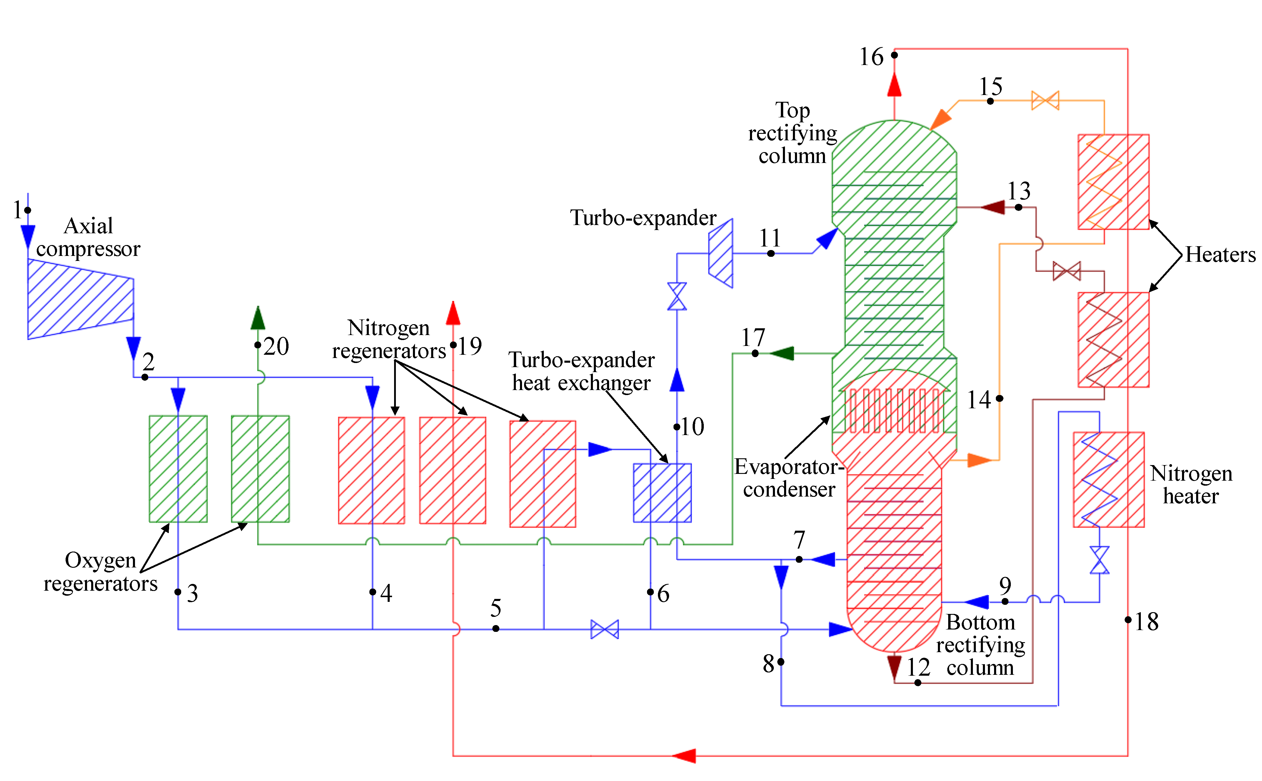
| Flow No | Description | Mole Fraction, % | Mass Flow Rate, kg/s | Temperature, °C | Pressure, MPa | |
|---|---|---|---|---|---|---|
| O2 | N2 | |||||
| 1 | Air compressor inlet | 0.209 | 0.791 | 1 | 15 | |
| 2 | Air compressor out | 0.1 | ||||
| 3 | Air after oxygen regenerator | 0.209 | 0.791 | 1 | 30 | 0.589 |
| 4 | Air after nitrogen regenerator | 0.209 | 0.791 | 0.205 | −172 | 0.574 |
| 5 | Air after mixing | 0.209 | 0.791 | 0.795 | −172 | 0.574 |
| 6 | Air after turbo-expander heat exchanger hot side | 0.209 | 0.791 | 1 | −172 | 0.574 |
| 7 | Air after lower column | 0.209 | 0.791 | 0.115 | −113 | 0.574 |
| 8 | Air in nitrogen heater | 0.209 | 0.791 | 0.248 | −173 | 0.574 |
| 9 | Air from nitrogen heater | 0.209 | 0.791 | 0.011 | −173 | 0.574 |
| 10 | Air in turbo-expander from heat exchanger cold side | 0.209 | 0.791 | 0.011 | −175.5 | |
| 11 | Air after turbo-expander | 0.209 | 0.791 | 0.248 | −158 | 0.539 |
| 12 | Crude liquid oxygen from lower column | 0.209 | 0.791 | 0.248 | −188 | 0.13 |
| 13 | Crude liquid oxygen from heater | 0.38 | 0.62 | 0.404 | −174 | 0.56 |
| 14 | Nitrogen reflux from lower column | 0.38 | 0.62 | 0.404 | −176.5 | 0.130 |
| 15 | Nitrogen reflux from heater | 0.01 | 0.99 | 0.348 | −178 | 0.55 |
| 16 | Nitrogen from upper column | 0.01 | 0.99 | 0.348 | −191.3 | 0.13 |
| 17 | Oxygen from upper column | 0.99 | 0.01 | 0.790 | −193.8 | 0.125 |
| 18 | Nitrogen from nitrogen heater | 0.956 | 0.044 | 0.210 | −178 | 0.135 |
| 19 | Nitrogen output | 0.99 | 0.01 | 0.790 | −178 | 0.1175 |
| 20 | Oxygen for Allam cycle | 0.99 | 0.01 | 0.790 | 26 | 0.0975 |
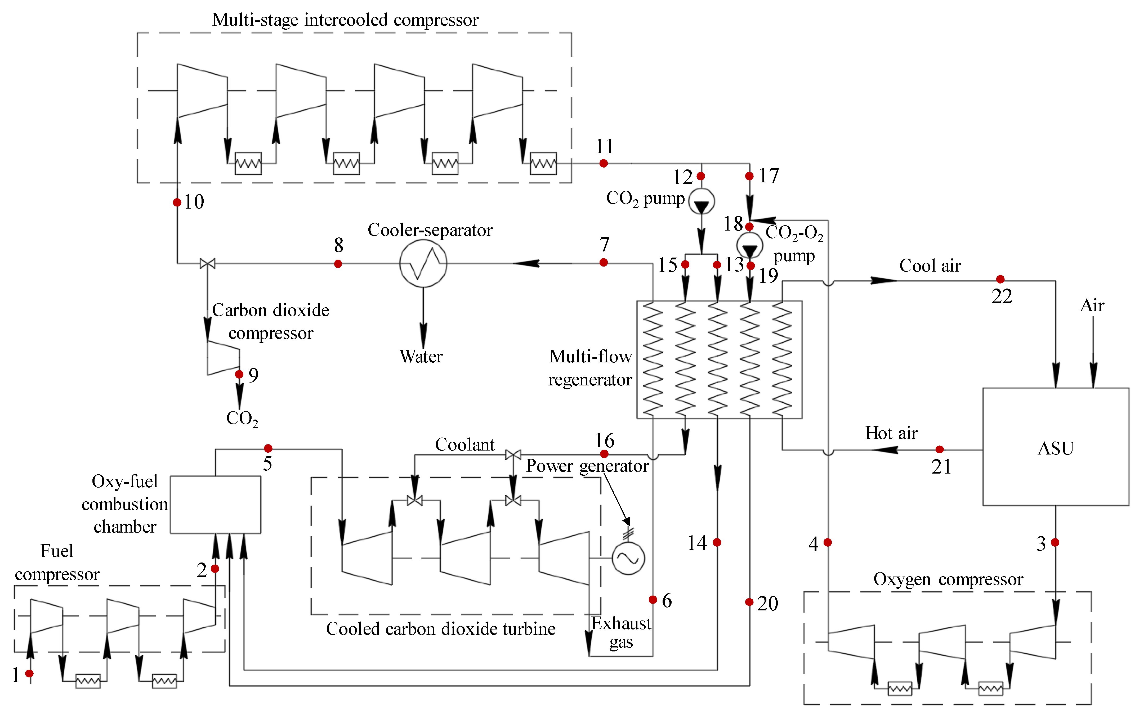
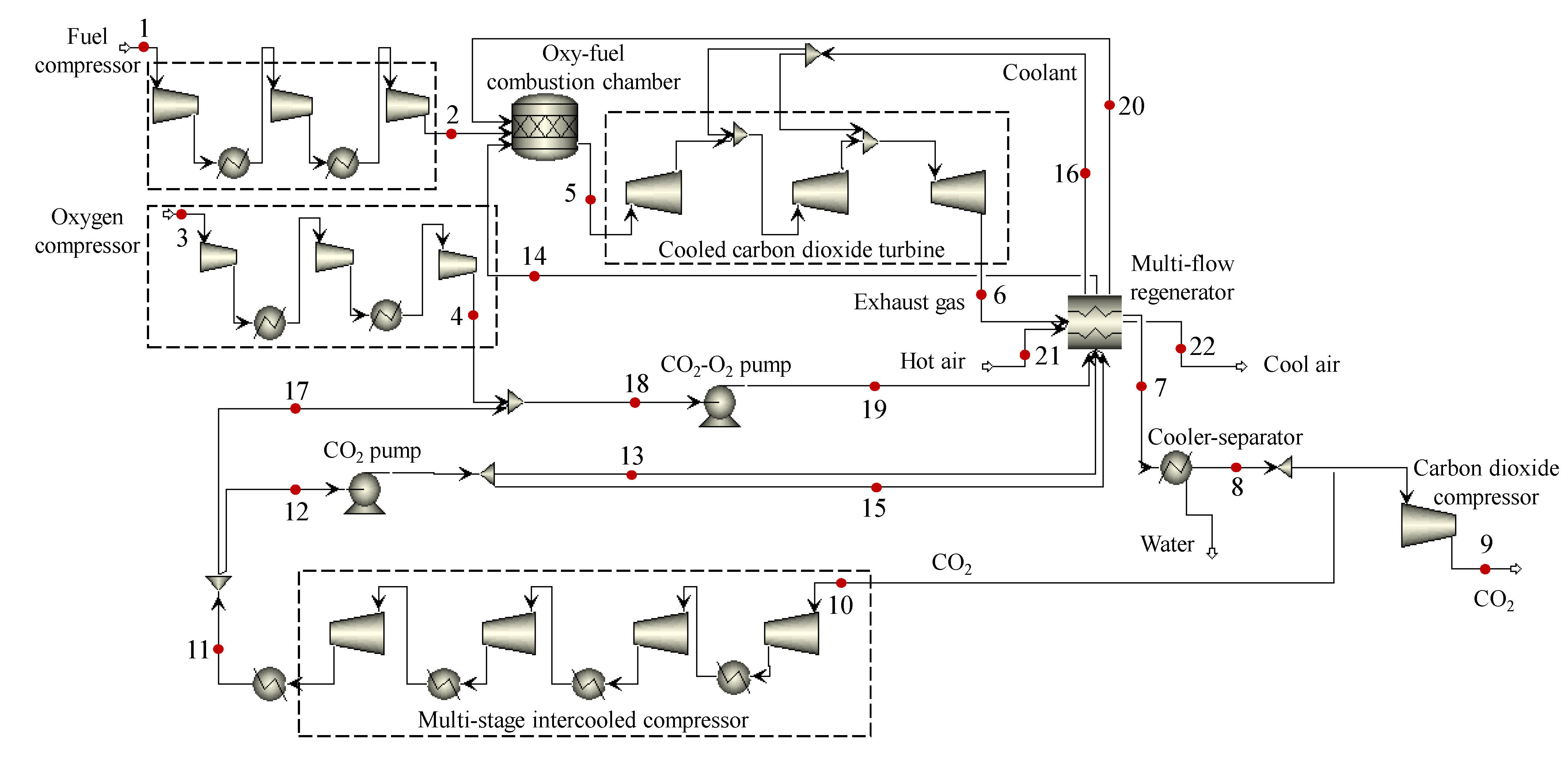
| Flow No | Description | Mass Fraction, % | Mass Flow Rate, kg/s | Temperature, °C | Pressure, MPa | ||||
|---|---|---|---|---|---|---|---|---|---|
| CH4 | O2 | N2 | CO2 | H2O | |||||
| 1 | Fuel compressor inlet | 1 | - | - | - | - | 7.33 | 15 | 0.7 |
| 2 | Fuel compressor outlet | 1 | - | - | - | - | 7.33 | 147.9 | 30 |
| 3 | Oxygen compressor inlet | - | 1 | - | - | - | 29.3 | 26 | 0.1175 |
| 4 | Oxygen compressor outlet | - | 1 | - | - | - | 29.3 | 190.6 | 8 |
| 5 | Carbon dioxide turbine inlet | - | - | - | 0.974 | 0.026 | 618.8 | 1083 | 30 |
| 6 | Carbon dioxide turbine outlet | - | 0.975 | 0.025 | 636.6 | 703.3 | 3 | ||
| 7 | Cooler–separator inlet | - | - | - | 0.975 | 0.025 | 636.6 | 86 | 3 |
| 8 | Cooler–separator outlet | - | - | - | 0.9975 | 0.0025 | 621.7 | 55 | 3 |
| 9 | Carbon dioxide storage | - | - | - | 0.9975 | 0.0025 | 21.7 | 28 | 10 |
| 10 | Multi-stage compressor inlet | - | - | - | 0.9975 | 0.0025 | 600 | 55 | 3 |
| 11 | Multi-stage compressor outlet | - | - | - | 0.9975 | 0.0025 | 600 | 30 | 8 |
| 12 | CO2 pump inlet | - | - | - | 0.9975 | 0.0025 | 328.2 | 30 | 8 |
| 13 | Main CO2 flow in multi-flow regenerator | - | - | - | 0.9975 | 0.0025 | 310.4 | 74.3 | 30 |
| 14 | Main CO2 flow from multi-flow regenerator | - | - | - | 0.9975 | 0.0025 | 310.4 | 658.6 | 30 |
| 15 | Coolant flow in multi-flow regenerator | - | - | - | 0.9975 | 0.0025 | 17.8 | 74.3 | 30 |
| 16 | Coolant flow from multi-flow regenerator | - | - | - | 0.9975 | 0.0025 | 17.8 | 200 | 30 |
| 17 | CO2 flow for mixing with O2 | - | - | - | 0.9975 | 0.0025 | 271.8 | 30 | 8 |
| 18 | CO2–O2 pump inlet | - | 0.097 | - | 0.9 | 0.003 | 301.1 | 18.2 | 8 |
| 19 | CO2–O2 pump outlet | - | 0.097 | - | 0.9 | 0.003 | 301.1 | 80.6 | 30 |
| 20 | CO2-O2 at combustion chamber inlet | - | 0.097 | - | 0.9 | 0.003 | 301.1 | 658.6 | 30 |
| 21 | Air from ASU compressor | - | 0.233 | 0.767 | - | - | 139.03 | 241.4 | 0.589 |
| 22 | Air from multi-flow regenerator | - | 0.233 | 0.767 | - | - | 139.03 | 79.3 | 0.589 |
Publisher’s Note: MDPI stays neutral with regard to jurisdictional claims in published maps and institutional affiliations. |
© 2021 by the authors. Licensee MDPI, Basel, Switzerland. This article is an open access article distributed under the terms and conditions of the Creative Commons Attribution (CC BY) license (https://creativecommons.org/licenses/by/4.0/).
Share and Cite
Rogalev, A.; Rogalev, N.; Kindra, V.; Zlyvko, O.; Vegera, A. A Study of Low-Potential Heat Utilization Methods for Oxy-Fuel Combustion Power Cycles. Energies 2021, 14, 3364. https://doi.org/10.3390/en14123364
Rogalev A, Rogalev N, Kindra V, Zlyvko O, Vegera A. A Study of Low-Potential Heat Utilization Methods for Oxy-Fuel Combustion Power Cycles. Energies. 2021; 14(12):3364. https://doi.org/10.3390/en14123364
Chicago/Turabian StyleRogalev, Andrey, Nikolay Rogalev, Vladimir Kindra, Olga Zlyvko, and Andrey Vegera. 2021. "A Study of Low-Potential Heat Utilization Methods for Oxy-Fuel Combustion Power Cycles" Energies 14, no. 12: 3364. https://doi.org/10.3390/en14123364