1. Introduction
There is a strong need for high-performance low-cost power sources to meet the energy demands of electronic devices ranging from the micro scale to the macro scale. Lithium batteries have served the purpose of energy supply for applications that require economical and efficient storage of energy so far [
1]. Some advanced batteries such as zinc-bromine, hydrogen bromine flow, and vanadium redox batteries have been developed [
2,
3], which introduce innovative concepts such as integrating organic electrolytes to produce higher voltage stability and utilization of semisolid reactants for higher energy density [
4,
5]. However, Kurtzweil [
6] and Dyer [
7] found that fuel cells are capable of providing energy density of around 4000–7000 Whl
−1, whereas that of lithium batteries is only around 650 Whl
−1. Furthermore, fuel cells are more reliable and have a longer life time than batteries [
8].
Numerous fuel cells are being developed due to their higher energy density [
7,
9]. Fuel cells are promising energy-conversion devices addressing the energy crisis in all scales ranging from miniaturized power supplies to larger-scale power plants. Miniaturization of fuel cells increases the surface-to-volume ratio to carry out the reaction swiftly and enhance fuel utilization. Thus, the current and power densities are improved, and the improvement in performance is inversely related to the characteristic channel length. As electrochemical reactions are primarily surface-based, the performance of the fuel cells tend to benefit from miniaturization. Miniaturizing fuel cells also enables cell stacking to produce a large amount energy [
10]. Developments in the miniaturization of power sources have led to a new class of power-generating devices [
11].
Miniaturized fuel cells or micro fuel cells (MFCs) primarily use a proton exchange membrane (PEM) to conduct protons. MFCs are energy sources for various portable electronic and MEMS devices [
12]. An advantage of MFCs is their long-lasting performance as a power source. However, there are major issues and challenges to solve. For example, there are key problems in current designs related to the PEM. To ensure higher proton conductivity, cyclic humidification and cooling are required to avoid shrinkage, swelling, and degradation of the PEM, which add complexity to MFC systems. Additionally, fuel crossover through the PEM degrades the cell performance. To fix these problems, novel micro-scale fuel cell designs have been developed [
13].
Laminar flows allow the streams of different species to travel in a microchannel without actively mixing. Diffusive mixing between two adjacent streams results in limited development of a mixing region. Membraneless microfluidic fuel cells (MMFCs) were developed by exploiting the properties of meticulous microfluidic interface [
13]. MMFCs are a new type of fuel cell that are distinct from other mainstream fuel cells, i.e., proton exchange membrane fuel cells (PEMFCs) [
14], molten carbonate fuel cells, direct methanol fuel cells (DMFCs), alkaline fuel cells (AFCs), and solid oxide fuel cells (SOFCs). MMFCs are micro-fabricated devices that produce electrical power via electrochemical reactions involving an oxidant and a fuel, and their delivery and removal are integrated in a single microchannel. Since their first appearance [
13,
15], MMFCs have attracted attention for their working concept, ease of miniaturization, and utility as a power source for portable devices [
16,
17,
18,
19,
20]. MMFCs use parallel co-laminar flows of oxidant and fuel to avoid complete mixing [
21]. The interface of the oxidant and fuel streams acts as pseudo-membrane and allows the conduction of ions, whereas conventional fuel cells use a membrane for ion exchange [
22].
Since the fuel and oxidant flows in MMFCs are laminar with a low Reynolds number, slow diffusion occurs at the fuel-oxidant interface without aggressive convection, which leads to a limited diffusive mixing zone at the center of the microchannel. The elimination of the membrane leads to various benefits compared to conventional membrane fuel cells. Membrane degradation is no longer a concern, and there is no excessive fuel crossover with degradation of the membrane. Furthermore, humidification and cooling are not required, and the choice of fuels and oxidants is flexible. MMFCs can also be made smaller and more compact [
14,
23,
24,
25,
26,
27]. However, the economic aspects are the most prominent advantage. MMFCs can be mass-produced using conventional low-cost methods for microfabrication and micromachining, and the membrane cost is eliminated as well. Furthermore, an MMFC functions efficiently at room temperature.
Previous reviews of MMFCs focused mainly on the architecture, fundamental nature, and performance. Kjeang et al. [
24] summarized the developments in various types of MMFCs and briefly explained architectures, fabrication techniques, and types of fuels and oxidants. Tanveer et al. [
28] discussed the mass-transport and its impact on the performance of MMFCs. They summarized the computational modeling techniques, future challenges, and opportunities.
Shaegh et al. [
17] reviewed electrode architectures and their impacts on the performance of MMFCs. They briefly explained the losses involved in different types of electrode design, such as flow-over, flow-through, and air-breathing designs, as well as the power density and fuel utilization. Goulet et al. [
21] described the trends in research on MMFCs and found that further improvements in performance be achieved. They also provided recommendations for future research. Hannapi et al. [
29] presented an overview of the system design for different microchannel shapes and the resulting performance of MMFCs. They briefly summarized the working principles, microchannel and electrode architectures, fabrication methods, types of catalysts, and performance of MMFCs.
However, substantial development is still required to solve the problems of lower volumetric power density and insufficient utilization of reactants, which are two fundamental setbacks for the pervasive use of MMFCs. Mass-transport and ohmic losses are key issues that decide the performance of an MMFC. Fuel utilization and volumetric power density can be improved if the mass-transport and ohmic losses are decreased. To accomplish this, various flow configurations with different electrodes and arrangements have been studied. Improving the fuel utilization improves the mass-transport, and vice versa, resulting in higher power output (current and power densities).
The mass-transport of the oxidant and the fuel in the MMFC system also need to be remedied to shrink the diffusive mixing region of the two streams because this dissuasive interface between the streams is the only thing that provides the function of a membrane. The diffusive mixing region is a major performance-limiting factor. The diffusive mixing region degrades the overall MMFC performance by (a) mitigation of the oxidant/fuel concentrations, which leads to decrease in current density; (b) resistance to ion transport, which increases the ohmic losses; and (c) fuel crossover from the anodic to the cathodic channel, which decreases the open-circuit potential. Therefore, the fundamental elements to enhance the mass-transport in an MMFC system are reducing the diffusive mixing region between the oxidant and fuel and the depletion region at the surfaces of the electrodes. This can be achieved by modifying the flow configuration and electrode arrangement.
Various flow configurations of MMFCs have been studied. The flow configurations were reviewed by classifying them into six categories: (a) co-laminar flow MMFCs (CLFMMFCs), (b) single-stream MMFCs (SSMMFCs), (c) counter-flow MMFCs (CFMMFCs), (d) radial-flow MMFCs (RFMMFCs), (e) orthogonal-flow MMFCs (OFMMFCs), and (f) lateral-flow MMFCs (LFMMFCs). CLFMMFCs were further divided into five subcategories: (a) side-by-side stream, (b) vertical-layered stream, (c) multi-stream, (d) dual-pass, and (e) recirculation CLFMMFCs.
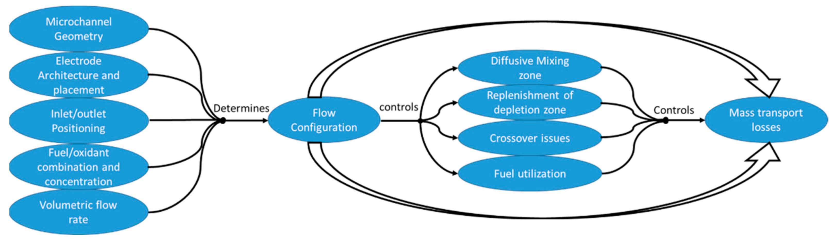
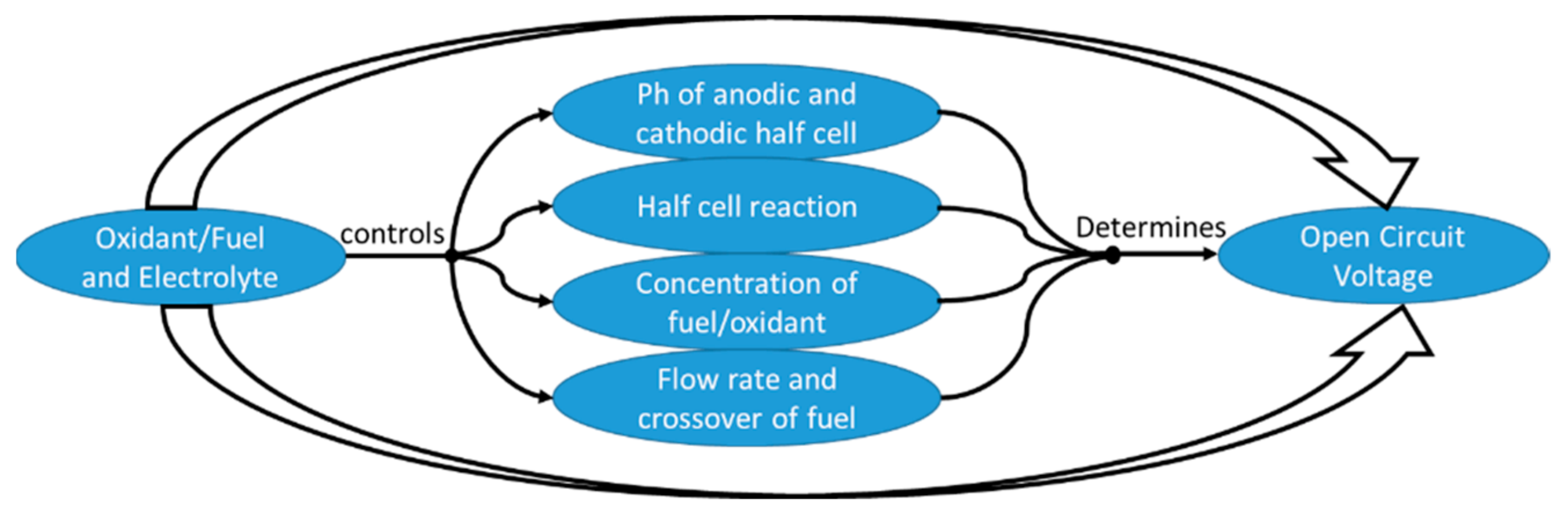
A concept map is outlined to develop a general understanding of the parameters affecting the flow configuration and how they impact the performance of an MMFC, as shown in
Figure 1. The concept map provides a clear summary for understanding the related problems in MMFCs [
30].
2. Fundamentals of MMFCs
The fundamental electrochemical conversion principle of membrane fuel cells applies to MMFCs. The main difference is that the fuel-oxidant interface (the diffusive mixing region) plays the role of the membrane by transporting ions and separating the anodic and cathodic half-cells in a microchannel. Oxidant and fuel streams are inserted separately into the channel and create a fuel-oxidant interface when they come in contact and flow in the channel. The microchannel walls support the current collectors and electrodes coated with an appropriate catalyst, where electrochemical reactions occur mainly.
The fuel and oxidant streams are mixed with an ionic conductive electrolyte (acidic, alkaline, or mixed) to accomplish a uniform ionic transportation between the two anodic and cathodic channels. The electrolyte mixed with the fuel and oxidant streams contains hydroxide or hydrogen ions (basic or acidic solutions), which ensures the nature of working media in the MMFC, either acidic, alkaline, or mixed. Commonly, the microchannels have a characteristic length greater than 1 μm and less than 1 mm [
23], and the fluid flow within the microchannel is analyzed by microfluidics.
A set of steady-state conservation equations is used to numerically simulate MMFC operation to estimate the effects of ohmic, activation, and mass-transport losses on the performance of MMFCs. Microfluidic flows inside microchannels with smaller dimensions and lower velocities are characterized by low Reynolds numbers. The flow structure is represented by Navier–Stokes and continuity equations [
31]. The hydroxide or hydrogen ions are supposed to be uniformly distributed in the anodic and cathodic compartments. The transportation of ions is controlled by electric migration from the anodic compartment to the cathodic compartment. The electric field is determined by the potential equation by quantifying the transport of charged species for the aforementioned conditions.
The velocity field determined using Navier–Stokes equations is used to calculate the transport of reactant species and the concentration distribution. The transport of reactants along the microchannel’s characteristic length occurs through convection. It is necessary to remove the depleted reactant species near the electrodes, which is achieved by diffusive transport.
A low concentration of reactant species is the major cause of mass-transport losses. Mass-transport losses play a vital role in limiting the MMFC potential at higher current densities when an MMFC is working at lower flow rates due to slower replenishment of depleted reactants at the electrodes. The design and flow configuration of an MMFC play a vital role in decreasing mass-transport losses. When concentrations of reacting species are low, the diffusion rates and concentration gradients are considered linearly proportional [
32]. Fick’s law [
31] is used to find the concentration distributions of the oxidant and fuel. In the electrochemical reactions, fuel and oxidant are oxidized and reduced over the anode and cathode, respectively, which results in electric current. The Butler–Volmer equation [
33] is used to find the current density.
3. Architecture and Fabrication
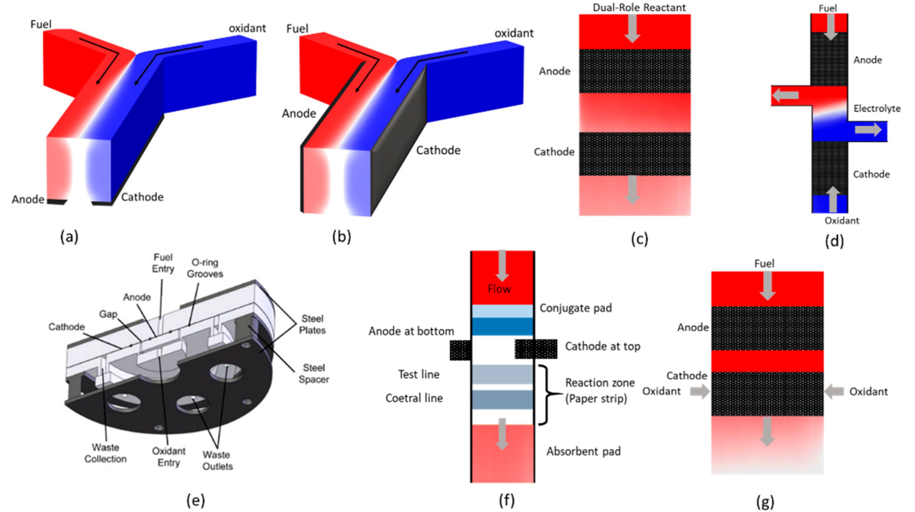
Figure 2 shows MMFC design variations based on multiple flow configurations. This figure characterizes the strategic conceptual improvements in MMFCs to date. Different fabrication methods are used to achieve different flow configurations inside microchannels, and there are many ways of developing MMFC systems. The type of material, dimensions, and geometry influence the fabrication method of the system. MMFCs can be fabricated by cost-effective, well-recognized processes, such as photolithography, soft-lithography, and micro machining.
Figure 2a shows a CLFMMFC, where both the fuel and oxidant flow in a co-laminar way down the channel. The first CLFMMFC was proposed by Ferrigno et al. [
13]. They fabricated a Y-intersection microfluidic channel having two inlets and a single outlet [
13]. Hollinger and Kenis [
34] shed light onto the fabrication and manufacturing of CLFMMFCs. A device was fabricated using soft-lithography with poly-dimethyl-siloxane (PDMS), which is used for multiple other microfluidic applications and devices. The electrodes were referred to as planar “flow-over” electrodes. They were placed on the bottom of the central channel, and the co-laminar flow interface was formed normal to the electrodes during operation.
Since the electrodes are glazed on microfluidic channels and were parts of the same layer, this single-layer monolithic cell design tended to be integrated into on-chip systems and other MEMS devices [
36]. Monolithic MMFCs with Y-shaped and T-shaped microchannels have been studied extensively [
20,
37,
38,
39,
40,
41,
42,
43,
44,
45,
46,
47,
48,
49,
50]. Their simple fabrication, operation, and implementation have drawn attention from various research groups. Choban et al. [
15] developed a similar MMFC, as shown in
Figure 2b. They introduced vertical layers in the design, where two electrodes were placed along the microchannel walls, and an encapsulation layer was used to separate the electrode surfaces. Two additional plates were used for sealing the assembly. The “flow-over” electrodes were placed parallel to both the flows of fuel and oxidant and the co-laminar interface. Vertical-layer CLFMMFCs [
15,
18,
34,
51,
52,
53,
54,
55,
56,
57,
58,
59] have evolved considerably. Many MMFCs are now fabricated in this way and have a configuration with a high aspect ratio and multi-layer sandwich structure [
34]. The fabrication of such MMFCs is cheap with a simple design, no lithographic method is involved in the fabrication, and the structure is easier to stack. However, these MMFCs are difficult to integrate with on-chip devices.
The SSMMFC [
60] shown in
Figure 2c is fabricated using photolithography and sputtering (a lift-off process). Film electrodes are patterned by photolithography and sputtering on glass slides. SSMMFCs use a simple membraneless planar structure with inexpensive catalysts, which ensures flexible designs that are easily stackable and integrated for on-chip applications. The CFMMFC [
61,
62,
63] shown in
Figure 2d keeps the fuel and oxidant separated by a non-reacting electrolyte stream, which lets them flow to different outlets without mixing diffusively. The original CFMMFC proposed by Salloum et al. [
61] uses three polymethylmethacrylate (PMMA) layers, which were fabricated by a CO
2 laser ablation system. The bottom layer serves as a current collector, and Toray carbon paper in the middle serves as porous flow-through electrodes. CFMMFCs have been extensively studied [
61,
62,
63,
64] while considering minimal diffusive mixing, which decreases the mass-transport loss significantly. Also, a CFMMFC can be investigated for larger chamber volume and electrode area to generate higher power density for portable applications.
The RFMMFC developed by Salloum et al. [
35] (
Figure 2e) differs from conventional CLFMMFCs because the fuel and oxidant flow in series instead of parallel. They fabricated an RFMMFC using a stainless-steel disk sandwiched between two milled PMMA plates. Flow-through electrodes based on Toray carbon paper were coated with Pt black catalyst. Current was collected by platinum wire connected to the electrodes. The RFMMFCs avoid advection of streams in parallel. This concept was also used by various researchers [
65,
66] to improve the mass-transport in MMFCs.
The LFMMFC shown in
Figure 2f uses paper-based material. Chromatography paper (Whatman grade 1) is conventionally used for fabrication, which allows reactants to flow laterally by means of capillary action. Various fabrication methods have been used to construct LFMMFCs, such as (i) photolithography, screen printing [
67,
68,
69], (ii) wax printing, stencil printing [
70], (iii) wax printing, screen printing, origami [
71], (iv) wax printing, sputtering [
72], (v) cutting, stacking [
73], (vi) origami, molecular imprinting [
74], (vii) wax printing, pencil drawing [
75], and (viii) ink-writing [
76]. These fabrication methods have been used for different purposes, design features, and applications of LFMMFCs.
The OFMMFC shown in
Figure 2g was proposed by Hayes et al. [
77] and allows fuel mixed with electrolyte to travel orthogonally to electrodes housed in Teflon-lined stainless-steel cylinders. It was fabricated using a machining process, and Toray paper-based disks were placed inside the cylinders as electrodes. OFMMFCs are very expensive to fabricate, but are less compatible for on-chip integration. Therefore, they have rarely been investigated further for commercialization and portable applications.
4. Design and Flow Configurations
The interfacial diffusive region of the fuel and oxidant performs as a pseudo-membrane. It acts as a conductive medium for ions and controls the mixing of the oxidant and fuel without crossover across the fuel cell. In short, MMFCs benefit from microfluidics to remove the membrane from conventional fuel cells and hence eliminate membrane-based problems, such as membrane fouling, water management, and damage [
13,
78]. Elimination of the membrane reduces the fuel cell’s size and provides flexibility in cell fabrication, design, and miniaturization [
13,
79]. Additionally, the composition and combination of the oxidant and fuel streams can be customized to take full advantage of the anodic and cathodic reaction kinetics [
57]. The design issues related to sealing the packaging is partially resolved because the oxidant and fuel flow through a single channel. MMFCs are compatible with lab-on-chip devices and other microfluidic systems as power sources.
The microfluidic channel is a major component of an MMFC, which is mainly made up of plastic materials, such as PMMA, PDMS, and silicone sheets. The substrate accommodates the reactant species, electrodes, and current collectors. Furthermore, MMFCs with paper-based or fabric-based substrate are also being studied. The syringe or peristaltic pumps are mainly employed to deliver fuel and oxidant streams into microchannel [
20,
80,
81,
82]. But, this method adds cost and complexity into the system. To simplify the MMFC system and reduce parasitic energy consumption, passive pumps without electricity input, such as gravity pump [
83], osmotic pump [
84], evaporation pump [
85], and in-situ gas pump [
86], have also been proposed to replace the active electric pump. Furthermore, paper-based MMFCs do not require pumping as reactant streams travel downstream by capillary action [
87]. The gravity pump siphons the electrolyte to a waste container placed at lower altitude from the reservoir; this phenomenon requires static working conditions and the flow rate decreases gradually. The osmotic pump draws the electrolyte continuously across a semipermeable membrane utilizing the concentration difference of water molecule. It can be integrated to portable devices and provide a stable flow rate. The evaporation pump draws the waste out of an MMFC by employing a volatile solvent to create negative pressure at the exit of the microchannel in a small chamber. In-situ gas pumping is suitable for MMFCs, which generate gas during anodic reaction (i.e., CO
2 in a formic acid MMFC). The generated gas draws the electrolyte automatically alongside towards the outlet. However, the flow rate is periodical due to the growth of gas bubbles.
Lower fuel usage per single pass, ohmic losses, and mass-transport losses significantly contribute to decreasing the power output, and are thus regarded as the foremost disadvantages of MMFCs. Various factors are concerned with the mass transport losses as explained in
Figure 1. Furthermore, the factors defining the ohmic losses are detailed in
Section 6. With both streams and electrodes in a single channel of an MMFC, the flow configuration significantly affects the performance. Several investigations were performed to find the effects of the flow configuration and electrode structure/arrangement on the fuel cell performance. All MMFC designs use alike oxidants and fuels, and can be fabricated by standard orthodox manufacturing methods with identical precision. All the proposed designs can use either acidic or alkaline electrolytes.
4.1. CLFMMFCs
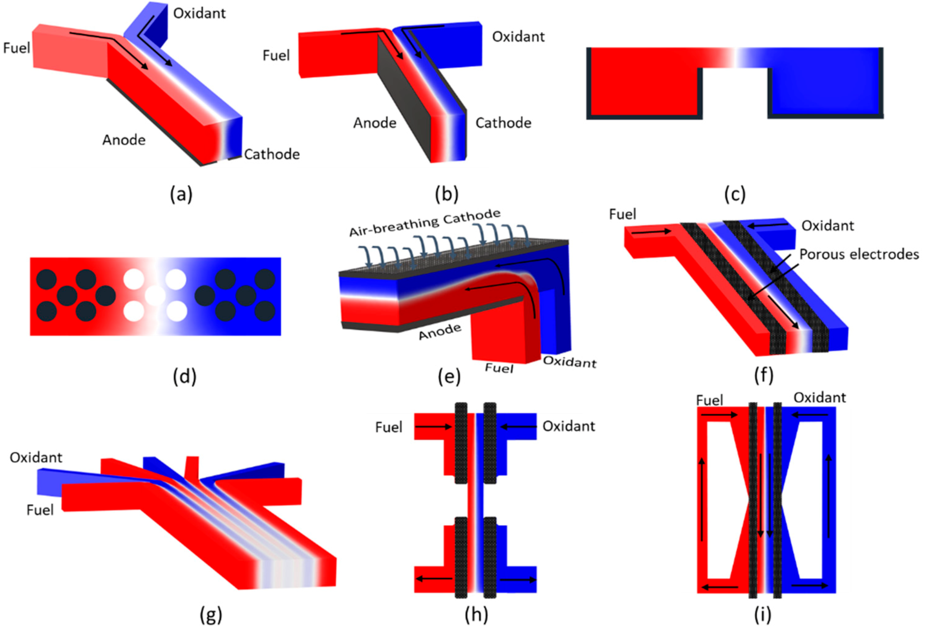
Figure 3 illustrates multiple modifications and significant developments made in CLFMMFCs in the past two decades since the first model was developed [
13]. All of the described designs use co-laminar flow of the oxidant and fuel, but they differ in the architecture, structure, or arrangement of the electrodes along the microchannel. The reactant streams in the CLFMMFC come in contact with electrodes in two configurations: side-by-side streaming, where a vertical fuel-oxidant interface develops side by side with a horizontal depletion region (
Figure 3a), and vertical-layered streaming, where a vertical fuel-oxidant interface and depletion region develop down the channel in the MMFC (
Figure 3b).
The fuel utilization in CLFMMFCs is greatly dependent upon the reactant flow rate and concentration, and can be described by the following equation:
where j is the current at a flow rate Q, n is the number of electrons transferred, C is the fuel concentration, and F is the Faraday’s constant. This fuel utilization can be increased by flowing fuel of low concentration at a lower flow rate. Since the flow rate and concentration determine the reaction residence time, mass-transport due to diffusion at the fuel/oxidant interface, reactant’s replenishment rate, and product’s advection. Nevertheless, it is also beneficial to expose the reactants to the largest possible reactive surface of electrodes. Larger surface area enlarges the reaction site, and reduces depleted layer, which subsequently increases the extracted current, whereas the fuel cell needs to be designed to house larger electrode area
4.1.1. CLFMMFCs with Side-By-Side Streaming
In the side-by-side flowing of the fuel and oxidant streams, the electrodes initially used were “flow-over” electrodes, and the fuel-oxidant interface formed perpendicular to the electrodes [
13], as shown in
Figure 3a. With a Y-shaped or T-shaped microchannel, this CLFMMFC architecture has led to numerous studies [
20,
37,
38,
39,
40,
41,
42,
43,
44,
45,
46,
47,
48,
49,
50]. Its simple operation and implementation let researchers investigate CLFMMFCs using biofuels with enzymatic or microbial catalysts [
40,
47,
48,
49,
50].
4.1.2. CLFMMFCs with Vertical-Layered Streaming
In vertical-layered streaming of the fuel and oxidant, the electrodes are placed on the channel walls parallel to the mixing layer [
15], as shown in
Figure 3b. This type of vertical-layered CLFMMFC has advanced extensively [
15,
18,
34,
51,
52,
53,
54,
55,
56,
57,
58,
59,
88]. It is well-suited for stacking and takes advantage of low-cost fabrication techniques with no lithographic method for fabrication. Considering the lower fuel utilization and ineffective mass-transport, multiple flow-over electrode arrangements have been studied for vertical-layered CLFMMFCs. Vertical-layered CLFMMFCs have been studied with various flow-over type electrodes, such as an array of electrically insulated graphite rod electrodes [
78], a cylindrical anode [
89,
90,
91], a grooved electrode surface [
92,
93], a tapered electrode [
32], and extended electrodes [
94].
To enhance the fuel utilization in vertical-layered CLFMMFCs, improved designs of channel/electrodes were used to provide effective area for electrochemical reactions, as shown in
Figure 3c,d. Montesinos et al. [
43] proposed a microchannel with a bridge-shaped cross section, as shown in
Figure 3c. The microchannel with bridge-shaped cross section effectively isolates the diffusive interfacial zone and depletion zone, reduces the fuel crossover, and enhances the maximum power density and fuel utilization in CLFMMFCs. Similarly, Kjeang et al. [
78] proposed a CLFMMFC using multiple graphite rods as anodes and cathodes, as shown in
Figure 3d. The insulated graphite rods in the center of the microchannel prevent fuel crossover and enhance the performance.
The flow-over designs let the oxidant and fuel streams flow over the planar electrodes, where they contact the catalytic layer and contribute to reactions. Owing to the insufficient convective mass-transport, a region known as the depletion boundary layer develops over both electrodes, which comprises reactants with low concentration. The depletion boundary layer prevents the reactants from reaching the electrodes’ reactive surfaces, which subsequently decreases the reaction rate and ultimately influences the performance of the CLFMMFC. Therefore, a thinner depletion boundary layer over an electrode is favorable [
15]. The thinner depletion drives more fresh reactants towards the active surface of the electrode.
An air-breathing type electrode was proposed by Jayashree et al. [
16]. Air-breathing electrodes minimize the thickness of the depletion boundary layer and generate a sharper concentration gradient, which results in a higher flux of reactants through the depletion region. They employed an air-breathing cathode electrode by substituting the graphite cathode with a porous gas diffusion electrode (GDE) hydrophobic in nature. The reduction occurring at the GDE consumes oxygen from ambient air, as shown in
Figure 3e. The air-breathing electrodes can be used in a CLFMMFC with H-shaped microchannel [
95,
96,
97,
98], but a Y-shaped microchannel [
16,
17,
89,
99,
100,
101,
102], T-shaped microchannel [
103,
104,
105], and F-junction microchannel with the inlets located on the same side have been studied more extensively. When coupled with the air-breathing electrodes, the products exit through a common outlet [
16,
90,
91,
106,
107,
108,
109,
110]. The air-breathing electrode concept was adapted from metal-air batteries [
60] or commercially available PEM fuel cells [
111] for MMFCs.
Kjeang et al. [
82] demonstrated flow-through electrodes for a CLFMMFC, where the reactant stream passes through the three-dimensional porous electrode that includes the active catalytic area, as shown in
Figure 3f. The flow-through porous electrodes primarily eliminate reactant-depletion complications at the electrodes and thus maximize the fuel utilization. The effective convective or diffusive mass-transport through porous electrodes continuously replenishes the depleted reactant concentration in the boundary layer. This results in better fuel utilization and enhances the power output. Goulet et al. [
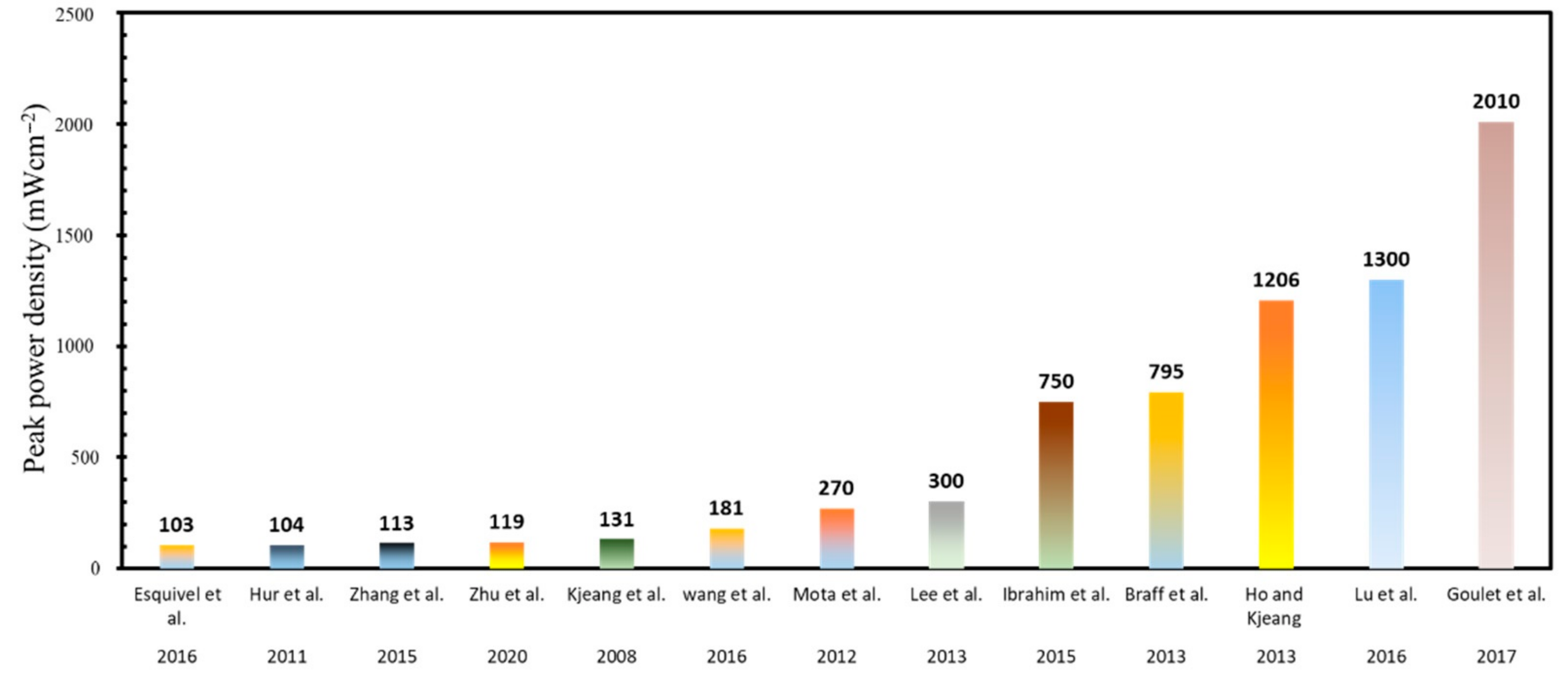
112] proposed an in-operando deposition of flow-through electrodes by employing temporarily suspended carbon nanotubes (CNTs) during the cell operation to enhance the reaction kinetics and mass transportation. By in-operando deposition of CNTs, they enhanced the surface area for electrochemical reaction and achieved a power density of 2010 mWcm
−2, which is the highest among all the MMFCs developed till date.
Several designs have been studied for side-by-side streaming combined with flow-through porous electrodes [
113,
114,
115,
116]. It has been illustrated in the literature that porous flow-through electrodes can also be used with vertical-layered CLFMMFCs [
103,
112,
117,
118,
119]. Li et al. [
120] used a vertical-layered CLFMFC with a flow-through electrode configuration to increase the fuel cell performance. Flow-through electrodes have been investigated in different combinations of air-breathing and flow-over electrodes [
95,
96,
97,
98,
100,
101,
104,
106,
108,
110]. Shaegh et al. [
17] reviewed different types of electrode architecture and their effects on the performance in detail. Additionally, CLFMMFCs have been investigated in derivate studies with modifications in the original flow configuration and were extended to multiple laminar flows (
Figure 3g) [
44,
121], innovative recirculation (
Figure 3h) [
122], and dual-pass configurations (
Figure 3i) [
123].
In essence, there is a trade-off between the fuel utilization and power density of a CLFMMFC. With an increase in power density by increasing fuel/oxidant flow rate, reducing channel length, etc., the fuel utilization tends to decrease. To improve the fuel utilization in flow-over designs without sacrificing power density, a better design of electrodes needs to be employed in the channel to explore more active areas to reactants for electrochemical reactions. These electrode architectures have been developed to replenish the depletion region quickly. The porous flow-through type electrodes and air-breathing electrodes have been implemented to enhance both the fuel utilization and power density.
The effective convective/diffusive mass-transportation through three-dimensional porous electrodes replenishes the concentration boundary layer continually, which subsequently increases the fuel utilization and results in a greater power output. The electrodes with flow-through architecture provide uniform reactant’s concentration over the reactive site for electrocatalysis. The lower concentration and diffusivity of dissolved oxygen as oxidant passively carry out the replenishment of the depletion region over cathode. Thus, replacing a flow-over type cathode with an air-breathing cathode provides oxidant form ambient air with higher concentration and diffusivity, which replenish the depletion boundary layer effectively.
4.1.3. Multi-Stream CLFMMFCs
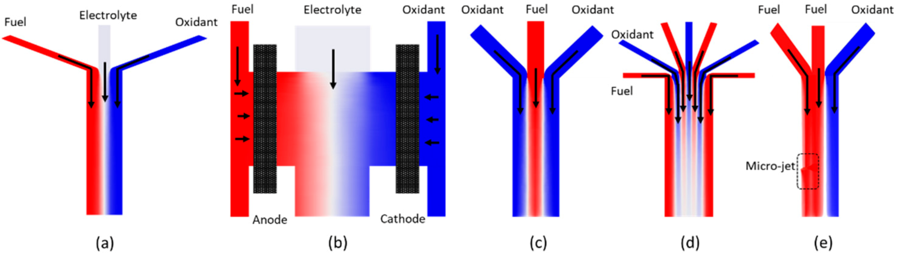
Sun et al. [
44] introduced a CLFMMFC using multiple streams of laminar flow to isolate the oxidant and fuel streams by inserting a third stream of electrolyte between them, as shown in
Figure 4a. The configuration with an electrolytic stream ensured the prevention of direct contact between the fuel and oxidant, which enhanced the fuel utilization and minimized the fuel crossover. Khabbazi et al. [
94] performed a numerical investigation of a multi-stream laminar flow in an MMFC. Most of the CLFMMFCs using air-breathing cathodes for oxidant reduction introduce an electrolytic stream to avoid fuel crossover. Kjeang et al. [
124], investigated a multi-stream MMFC with a flow-through porous electrodes architecture, as shown in
Figure 2b. They used a gaseous fuel and oxidant with a liquid electrolyte.
Tanveer and Kim [
66] investigated the multi-stream laminar flow of an oxidant-fuel-oxidant configuration for a CLFMMFC, as shown in
Figure 4c. Lee and Ahn [
121,
125] used the multi-stream laminar flow concept and put together multiple fuel and oxidant streams in parallel to achieve a planar stacked structure, as shown in
Figure 4d. Ahmed et al. [
126] proposed a trident-shaped CLFMMFC where the fuel, oxidant, and an electrolyte are inserted through three inlets to improve fuel utilization by using multi-stream laminar flow. Wu et al. proposed a CLFMMFC with continuous multi-stream flow through cotton threads [
127].
Zhou et al. [
101] used the multi-stream concept and fed a portion of fuel perpendicular to the anode to create an immersed micro-jet. The other portion of the fuel flow was parallel to the anode. The part of fuel flowing along the anode generates a concentration boundary layer, which is replenished by the fuel micro-jet directed perpendicularly toward the anode, as shown in
Figure 4e. The micro-jet created by immersed fuel improved the peak power density by 40.9%. A CLFMMFC where multiple streams of fresh reactants are inserted via periodically placed multiple inlets was also presented to enhance fuel utilization and rate of the electrochemical reaction [
54,
94].
Kwok et al. [
128] and Lu et al. [
129] employed air breathing cathode and fuel breathing anode with single and double electrolytic streams, respectively. Kwok et al. [
128] designed a novel solar assisted dual-fuel MMFC employing methanol and hydrogen. They carried out an in-situ hydrogen generation by the photocatalysis of methanol. They achieved a peak power density of 210 mWcm
−2. Whereas, Lu et al. [
129] investigated a dual electrolytic stream (i.e., both acidic and alkaline) switchable MMFC. They designed a switchable pH environment by coupling fuel with alkaline media and the oxidant with acidic media in fuel cell mode, while the media was switched in electrolysis mode. So, they achieved a peak power density and maximum current density of 1300 and 3600 mAcm
−2, respectively, in the fuel cell mode. This was possible by achieving an enhanced output voltage by carrying out oxidation at higher pH (i.e., acidic) and carrying out reduction at lower pH (i.e., alkaline).
Cascading multiple streams in a single channel increase power density, but reduce the freedom to employ electrodes involving complex architecture, which leads toward enhancement of both power density and fuel utilization. Therefore, multi-stream CLFMMFCs have not been investigated by employing flow-through anode with air-breathing cathode. However, the air-breathing cathode can be integrated by feeding the oxidant perpendicular to the flow of fuel, which may give an option to accommodate multiple air-breathing cathodes with flow-through anode arrangement.
4.1.4. Dual-Pass CLFMMFCs
The dual-pass idea was first used by Lee et al. [
123] to develop the first membraneless microfluidic redox battery (MRB), where two electrodes are split into two sections for in-situ regeneration and to use the reactants efficiently, as shown in
Figure 5a. The upstream and downstream portions were characterized discretely. Dual-pass CLFMMFCs improve the performance by using the same in-situ regeneration by connecting two CLFMMFCs in parallel. Ibrahim et al. [
130] proposed a cell design with two separate portions featuring flow-through electrodes to enhance the power density. Ibrahim and Kjeang [
131] used a dual-pass CLFMMFC with non-aqueous electrolyte and achieved a power density of 550 mWcm
−2, which is almost two times greater than the power density produced by conventional non-aqueous CLFMMFCs. Ho and Kjeang [
132] created an array of dual-pass CLFMMFCs and generated a power density of 1206 mWcm
−2 using a bilateral array design, as shown in
Figure 5b.
4.1.5. CLFMMFCs with Recirculation
Recirculation is another way to carry out in-situ regeneration in CLFMMFCs and to use reactants efficiently. Recirculation is carried out to transport the unused reactants at the outlet of a microchannel to the inlet for reuse. Goulet and Kjeang [
122] fabricated a Y-shaped microchannel with flow-through electrodes for reactant recirculation and a dual-pass configuration, as shown in
Figure 6. They found that the reactant recirculation is a useful strategy to minimize reactant crossover, improve reactant utilization, and achieve higher power density in CLFMMFCs. However, recirculation has not been studied extensively for CLFMMFCs.
4.2. SSMMFCs
Hydrogen peroxide (H
2O
2) is used as an oxidant in MMFCs. Additionally, hydrogen peroxide can react as fuel by donating electrons and can thus perform a dual role [
133]. The dual roles of H
2O
2 can be achieved by selective catalysis of the electrode: silver nanowires accomplish oxidation of H
2O
2, while CNTs support Prussian blue to achieve the reduction of H
2O
2. This dual nature of hydrogen peroxide lays a path toward the development of SSMMFCs. This approach is applicable and limited to mixed pairs of fuel and oxidant that show very high electro-kinetic for a single electrolyte and do not react spontaneously. As fuel and oxidant solutions are mixed in a single stream, the issue of fuel crossover is eliminated in this type of MMFC.
Sung and Choi [
60] proposed an SSMMFC using an alkaline solution. They employed a silver oxide cathode for the reduction of hydrogen peroxide, and a nickel hydroxide anode to oxidize methanol. The mild catalytic activity and reaction kinetics resulted in a very low open-circuit voltage (OCV) of around 0.12 V and a power density of around 0.03 mWcm
−2. The power density was improved by reducing the electrode spacing, which decreased ohmic losses and improved mass-transport.
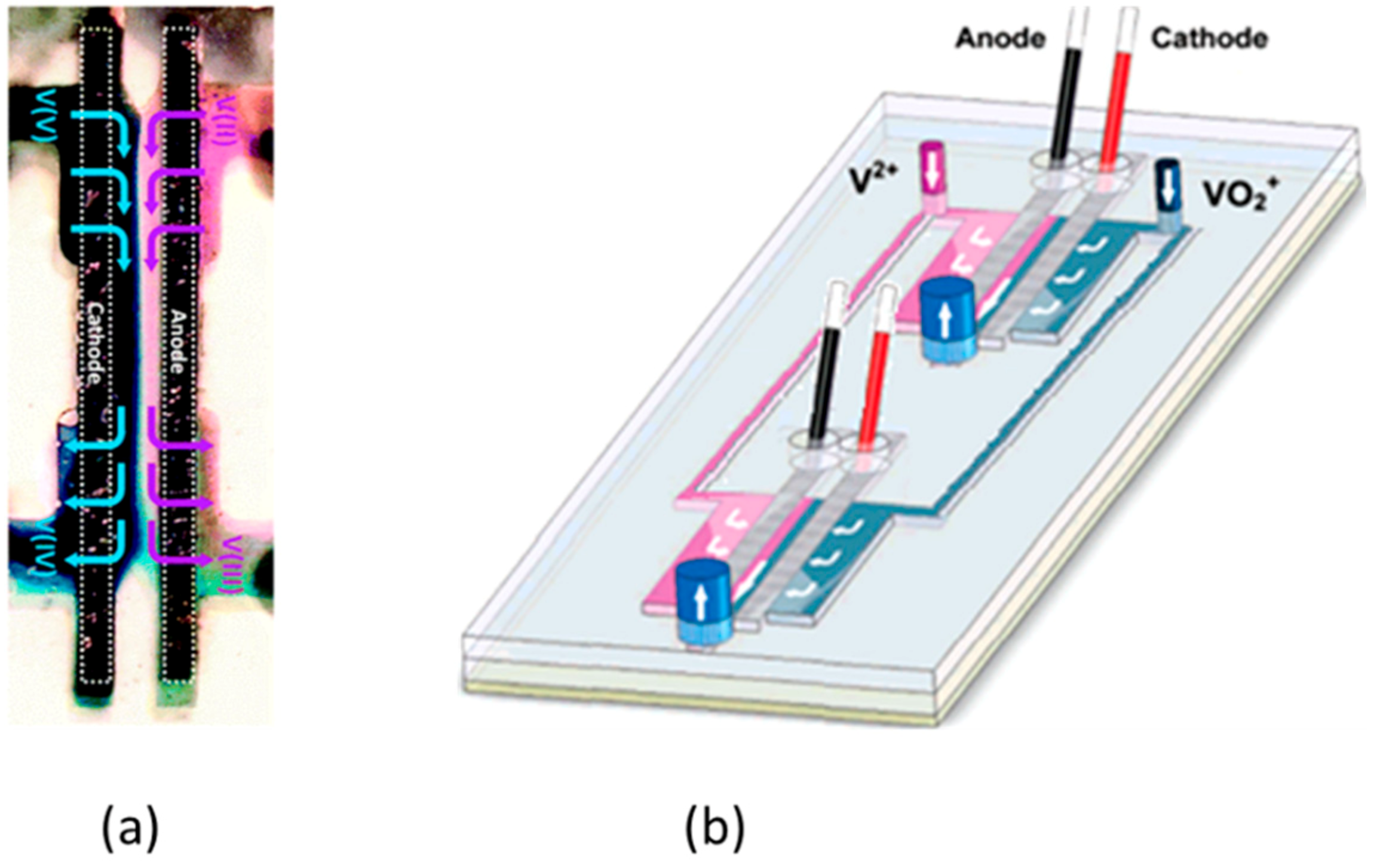
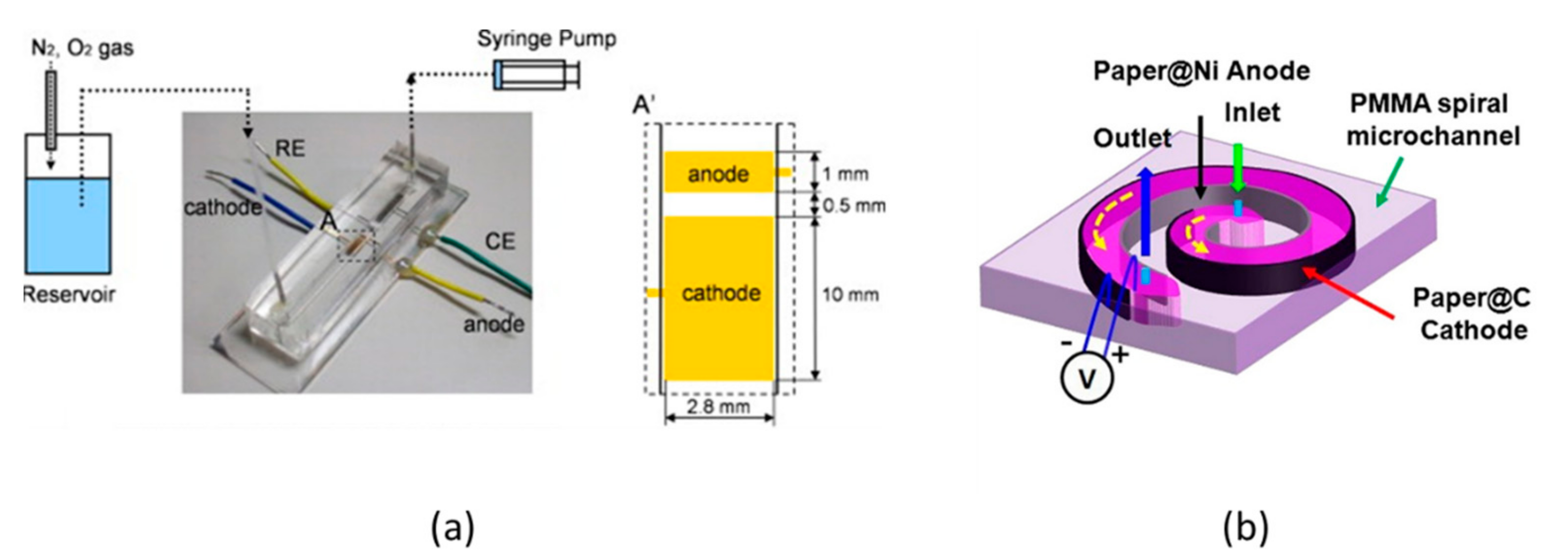
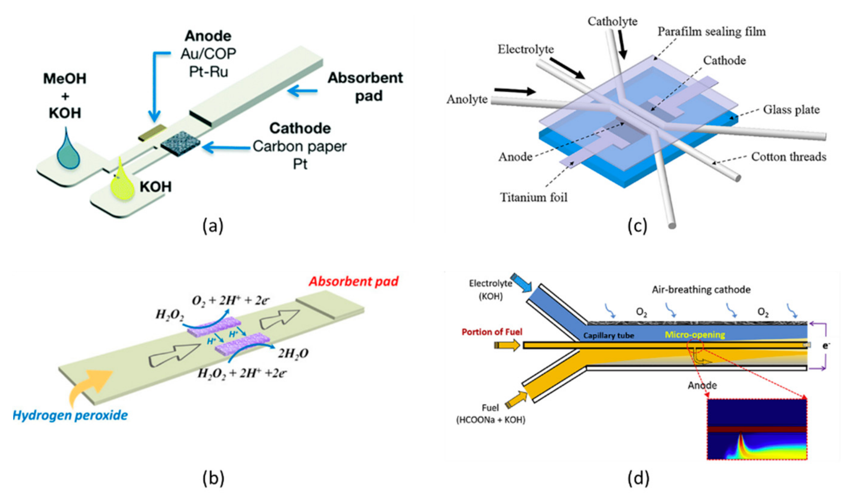
Togo et al. [
134] developed an SSMMFC using a bioanode with vitamin K3-mediated glucose as the fuel and a glucose dehydrogenase enzyme as the oxidant, as shown in
Figure 7a. Their SSMMFC generated a maximum power density of 32 μWcm
−2 at 0.29 V when 5 mM glucose (fuel) was inserted at a flow rate of 1 mLmin
−1. Recently, Togo et al. [
135] used a bilirubin oxidase-adsorbed biocathode instead of a Pt cathode. The maximum power density generated was comparable with that of a previous device [
134].
Arun et al. [
136] developed a vanadium-based spiral-shaped SSMMFC using a carbon cathode and Ni anode with a fuel-electrolyte mixture of VOCl
3 and diluted H
2SO
4, as shown in
Figure 7b. The spiral-shaped microchannel was built on a 1.5-mm-thick PMMA sheet with a laser engraving machine. They found that the low pressure drops in the spiral-shaped channel with uniform ion distribution enhanced the mass-transport. This device generated a maximum current density and power density of about 51 mAcm
−2 and 10 mWcm
−2, respectively. The SSMMFCs fabricated on PMMA or PDMS have very low power densities and OCVs, so they have not been studied extensively. However, LFMMFCs with similar flow configuration have been studied extensively (as shown in
Section 4.5).
4.3. CFMMFCs
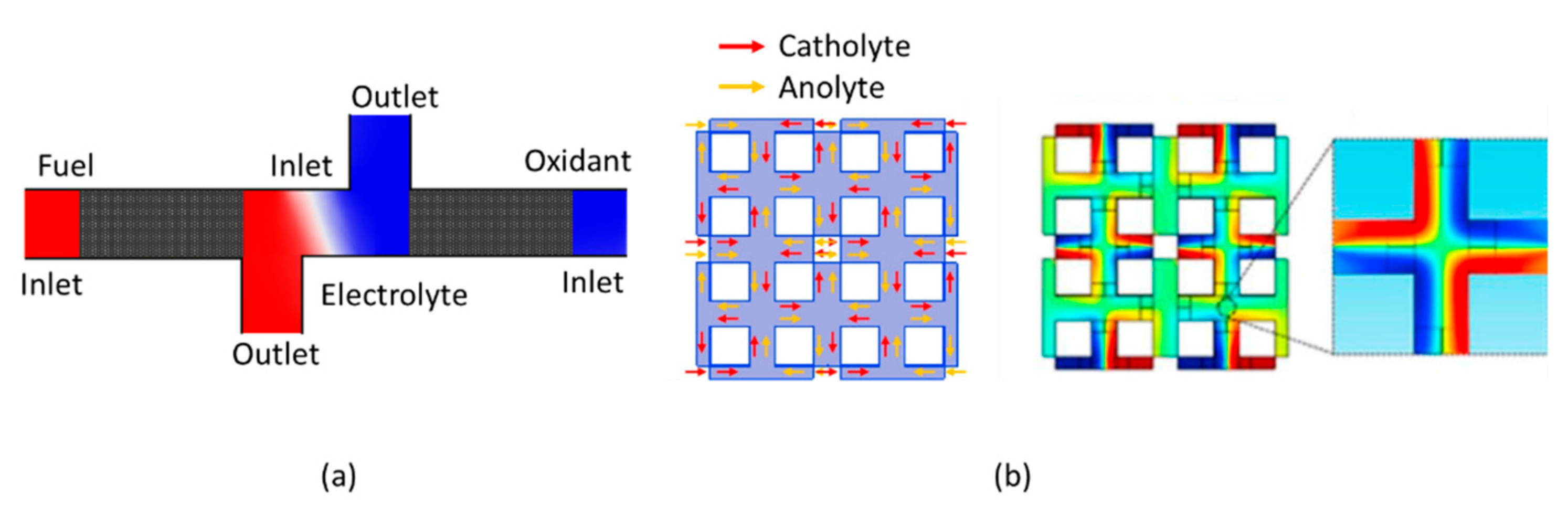
Salloum and Posner [
60] proposed a CFMMFC with vanadium redox species serving as the oxidant and fuel. The configuration relied on multiple streams, as proposed by Sun et al. [
43]. Sun et al. [
43,
44] used multiple streams in a co-laminar flow configuration, while Salloum and Posner [
61] used multiple streams in a counter-flow configuration, as shown in
Figure 8a. The CFMMFC prevents the fuel and oxidant from mixing in three ways: (i) using an ion conducting electrolytic stream at the interfacial diffusive region of the fuel and oxidant, (ii) using hydrodynamics to avoid mixing at the fuel and oxidant interface, and (iii) collecting the fuel and oxidant independently via distinct outlets, which also ensures their possible recirculation and reuse, as shown in
Figure 5a. CFMMFCs reduce the thickness of diffusive mixing zone and fuel crossover significantly in comparison with CLFMMFCs.
Lu et al. [
137] proposed a state-of-the-art upscaling approach for a CFMMFC network (
Figure 8b). They introduced a counter-flow-based dual-electrolyte protocol and observed that a counter-flow pattern enhances the reactive area for reactants. This approach was further investigated numerically by Lu et al. [
138]. Wang et al. [
139] investigated an air-breathing cathode in a CFMMFC. Xu et al. [
140] studied a CFMMFC for formic acid and oxygen streams at different flow rates and achieved a fuel utilization of 91.4% for formic acid at 1 μLmin
−1.
Wang et al. [
141] investigated and compared a CLFMMFC and CFMMFC experimentally and numerically. The experimental study found that the CLFMMFC produced an excellent peak power density of 2.9 mWcm
−2, while the CFMMFC generated a peak power density of around 1.6 mWcm
−2. CFMMFCs were further investigated in derivative studies to improve the performance [
61,
62,
63,
64,
141,
142].
CFMMFCs improve the power density by reducing the diffusive mixing and fuel crossover and enhancing ionic conduction, while fuel utilization is sacrificed largely. Salloum et al. [
61] found that the fuel utilization dropped drastically with a change in the flow rate from 50 μLmin
−1 to 300 μLmin
−1, while the power increase was not significant. They found a 20% increase in power density, whereas fuel utilization dropped by 91%.
4.4. RFMMFCs
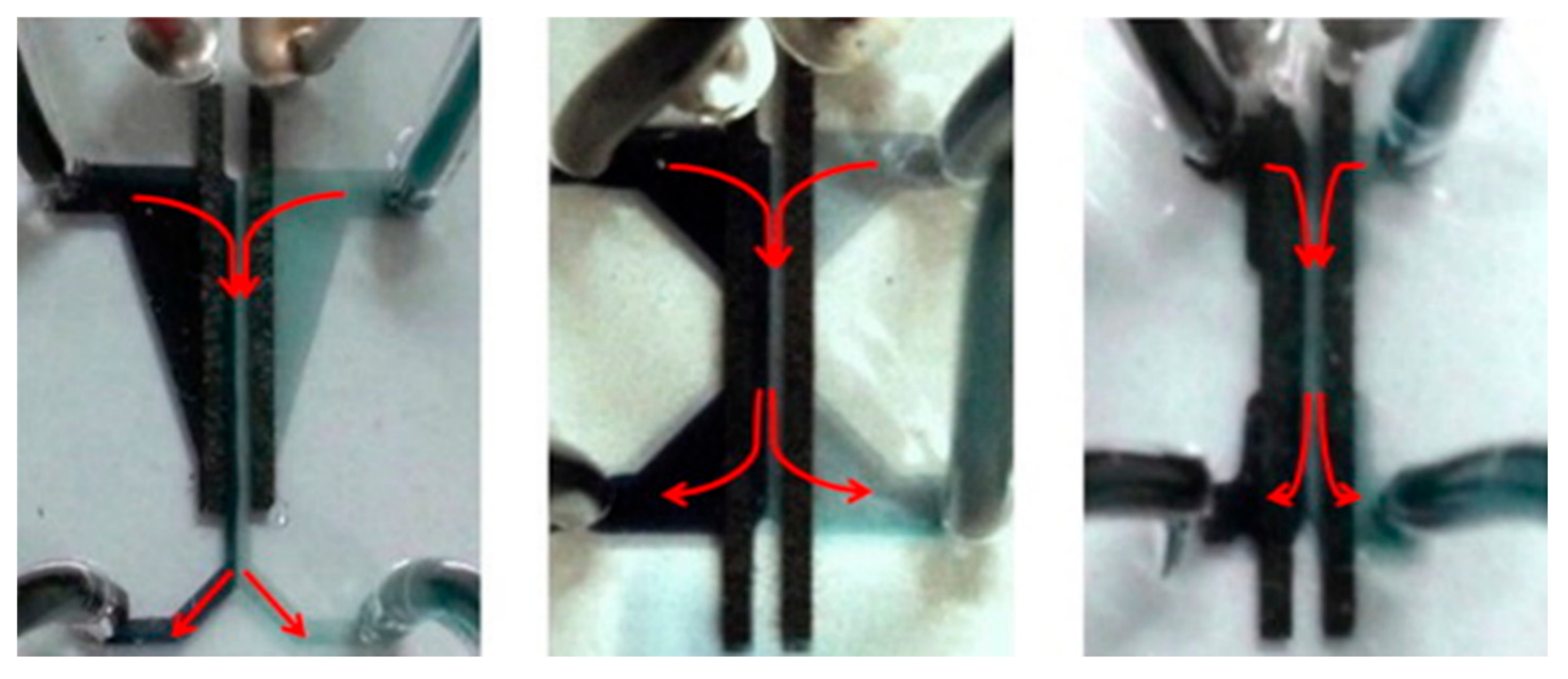
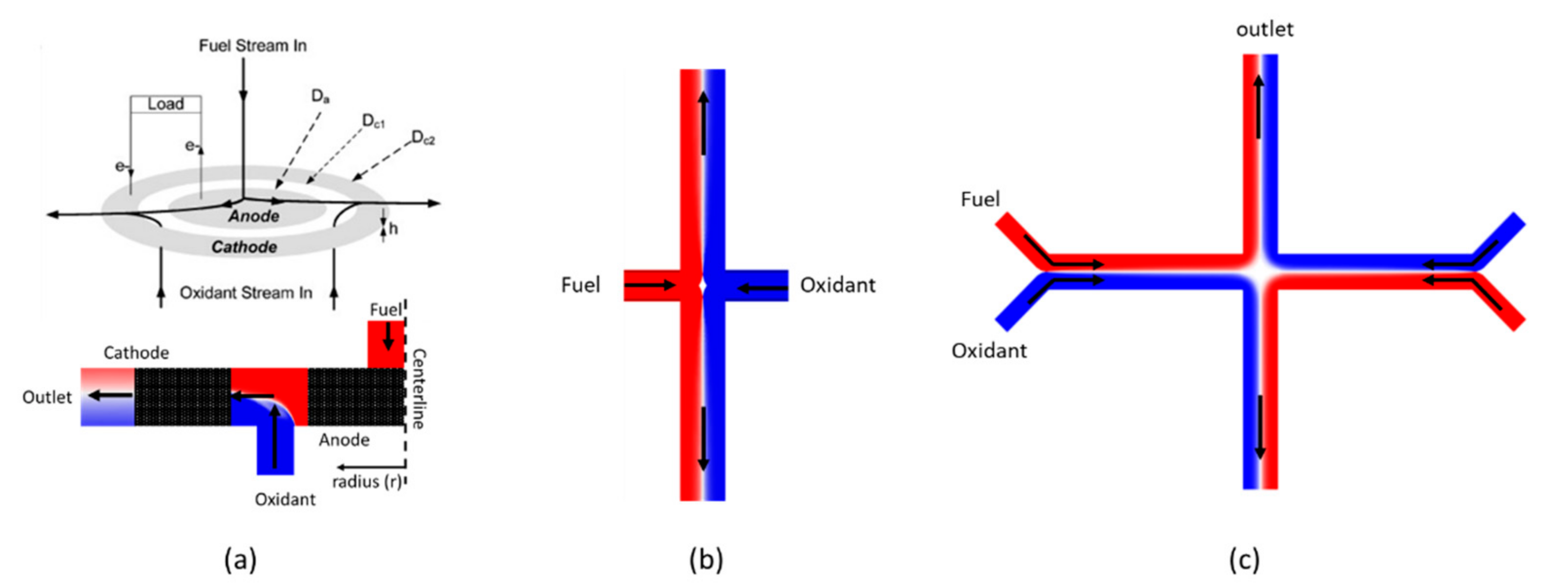
Manipulation of the fuel and oxidant’s transport patterns in MMFCs is vital to reduce the mass-transport losses and achieve higher performance. In RFMMFCs, the main flow splits into two halves, which travel down the channel and are directed opposite to each other. Radial flow alleviates the effects associated with excess channel length. Radial flow tailors and reduces the overall diffusive mixing and depletion regions to break the size limitation.
Salloum et al. [
35] conducted a study with a novel MMFC design using a disk-shaped flow-through anode and ring-shaped flow-through cathode. The fuel and oxidant were inserted radially, as shown in
Figure 9a. Fuel injected into the porous anode splits into two halves around the central line, while oxidant is injected from two different inlets, as shown in
Figure 9a. They found that increases in the flow rate and concentration of the electrolyte reduced the mass-transport and ohmic losses in the RFMMFC, which resulted in maximum current and power densities. By independently controlling the fuel and oxidant flow rates, the fuel utilization could be enhanced by up to 58%. Increasing the electrolytic concentration increased the maximum power density from 1.5 to 3 mWcm
−2.
Tanveer and Kim [
66] investigated an RFMMFC with various inlet locations along the microchannel to divide the active channel length into two halves and reduce the development length of the mixing layer. As shown in
Figure 9b, placing inlets at the middle of the microchannel reduces the thicknesses of the diffusive mixing and depletion regions at the outlets, thus reducing the mass-transport losses and enhancing the power and current densities by multiple times [
66]. Tanveer and Kim [
143] used co-laminar flow and radial-flow simultaneously in an MMFC with multiple inlets, as shown in
Figure 9c, which indicates a four-inlet channel. They found that eight inlets could increase the current density by 15 times in comparison with a conventional MMFC with two inlets.
Li et al. [
144] investigated an RFMMFC with flow-through porous electrodes. They found that a single fuel cell with a fuel and oxidant concentration of 2 mol·L
−1 and flow rate of 300 μLmin
−1 could produce a peak power of around 0.35 mW with 53.33% fuel utilization. Li et al. [
65] proposed using novel partially modified porous electrodes with the outlet at the channel center. This approach divides the electrochemical reaction zone (depletion region) into two halves, and reactions are carried out near porous electrodes’ outlet. The performance of the RFMMFC with the partially modified porous electrodes is analogous to that of a conventional MMFC with porous electrodes.
RFMMFCs provide better fuel utilization in comparison with CLFMMFCs and CFMMFCs. In MMFC with a co-laminar flow configuration, unused fuel and oxidant mix by diffusion form an interfacial zone, which subsequently decreases the maximum possible fuel utilization. The RFMMFCs pose the higher electrode surface area and reduce the length scale by splitting the stream into two directions, which reduce both depletion and mixing zones. The RFMMFCs have a distinct transport feature, which eliminates the linear diffusion interface responsible for reactant mixing and crossover in CLFMMFCs. The disc-shaped porous electrodes proposed by Salloum et al. [
35] for sequential RFMMFCs enlarged the overall reaction surface area, which resulted in higher fuel utilization. In a sequential design, any unused fuel either mixes with oxidants and depletes them, or cross over to react at the cathode, which causes mixed potentials. Therefore, it is compulsory to ensure the complete utilization of the reactant in the sequential flow pattern requires traveling through both the electrodes, either by tuning the oxidant and fuel flow rate to avoid crossover, or pairing the fuel and oxidant with the catalysts where they essentially carry out oxidation and reduction.
4.5. LFMMFCs
Osborn et al. [
145] illustrated that a paper strip allows two streams to flow in parallel. These streams were driven down the strip exclusively by the capillarity of cellulose paper pores without convective mixing. Using this phenomenon, Esquivel et al. [
87] introduced an LFMMFC using methanol and KOH. This type of laminar flow-based MMFC uses capillary action to make the fuel and oxidant streams flow inside a paper-based porous material, as shown in
Figure 10a. Using paper-based lateral strips in MMFCs eliminates the need for external pumping. Therefore, LFMMFCs benefit from the capillarity of paper-based porous strips and the laminar flow of the fuel and oxidant. These LFMMFCs with a self-pumping property further ease miniaturization and assure straightforward integration as a power supply, rapid fabrication, and low-cost manufacturing.
Table 1 summarizes the performance evolution of LFMMFCs.
The fabrication of LFMMFCs is very similar to that of lateral flow strips. They comprise a paper strip, absorbent pad, and conjugate pad. The anode and cathode are positioned on the top and bottom of the paper strip. LFMMFCs have been investigated for multiple flow configurations, as shown in
Figure 10. The LFMFC used by Esquivel et al. [
87] (
Figure 10a) achieved a power density of 5 mWcm
−2. Dector et al. [
165] investigated an LFMMFC installed in an HIV-test kit with blood as fuel. This paper-based LFMMFC attained a power density of 0.16 mWcm
−2. Rao et al. [
146] investigated an LFMFC for various grades of cellulose paper using formic acid as fuel and sulfuric acid as the electrolyte. This LFMFC produced a maximum current density of 1.5 mAcm
−2 and peak power density of 0.18 mWcm
−2.
MMFCs have been extensively studied with the vanadium redox couple (
/
). Jung and Ahn [
151] considered the effectiveness of the couple and used it in LFMMFCs. However, an LFMMFC using vanadium redox species (
) has been reported before [
152,
168]. Pasala and Ramanujam [
152] presented an LFMMFC that achieved a power density of 6 mWcm
−2. Yan et al. [
148] reported a one-reactant and one-component single-stream LFMMFC that used H
2O
2 as the fuel and oxidant, as shown in
Figure 10b. They used a silver nanowire anode and CNT cathode supported with Prussian blue to achieve the oxidation and reduction of H
2O
2. This MMFC eliminates the co-laminar flow and hence the fuel crossover, and it increases the maximum power density by up to 0.88 mWcm
−2.
Wu et al. [
127] developed a cotton thread-based multi-stream LFMMFC to eliminate fuel crossover and the need for a syringe pump, as shown in
Figure 10c. They fabricated this MMFC using cotton threads with sealing parafilm over a glass substrate and carbon-paper flow-through electrodes. Thread-based and fabric-based materials are alternatives to achieve lateral flow in microfluidic devices. They achieved a peak power density of 19.9 mWcm
−2 and maximum current density of 111.2 mAcm
−2.
Liu et al. [
167] fabricated a thread-based multi-stream LFMMFC and achieved a maximum power density of 20.7 mWcm
−2. Zhou et al. [
101] developed a multi-stream MMFC with an immersed micro-jet to replenish the depletion region and increase mass-transport using lateral flow in a capillary tube, as shown in
Figure 10d. They used a planar anode and air-breathing cathode made up of Toray carbon paper. They donned the immersed micro-jet by feeding a portion of the fuel into a titanium capillary tube and jetting fuel outside from a micro-opening perpendicular to the anode. The peak power density was 119.3 mWcm
−3. The proposed flow configurations for LFMFCs opened up new avenues to manipulate fluid flow and enhance mass-transport. LFMMFCs can be further investigated with dual-pass, radial-flow, and counter-flow configurations. Lateral flow strips can be cut into different shapes and can be cascaded to enhance the performance of the fuel cell.
4.6. OFMMFCs
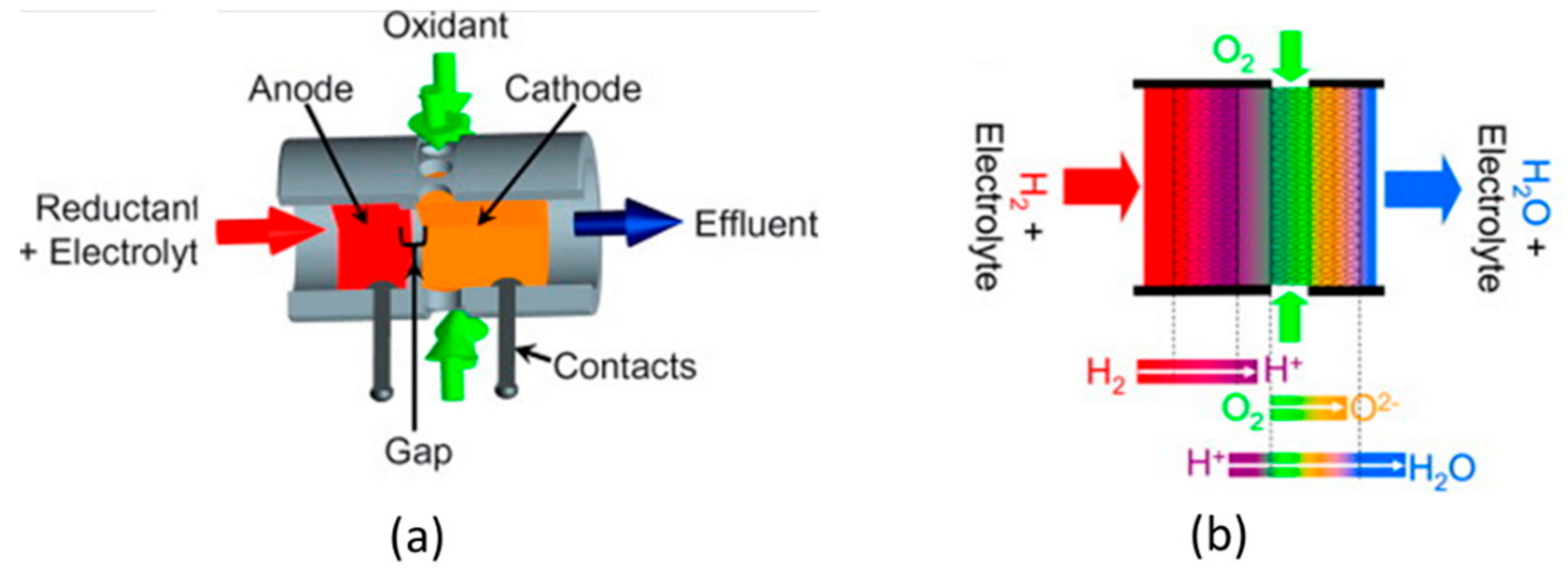
Hayes et al. [
77] proposed the orthogonal MMFC design shown in
Figure 11, where the fuel and oxidant cross each other orthogonally. They investigated two different systems: one with oxygen mixed with 1.8 M sulfuric acid as oxidant and hydrogen as fuel, and another with oxygen mixed with 1 M potassium hydroxide as oxidant and methanol as fuel. The orthogonal flow design prevents mixing and enhances the mass-transport because the oxidant and fuel streams have no diffusive mixing and are delivered convectively to the reaction site. The peak power density was 46 mWcm
−2 with 42% fuel (methanol) utilization. However, no derivative studies for OFMMFCs are found in the literature.
OFMMFCs can utilize the acidic, alkaline or mixed electrolyte. There is no restriction of the flow to be laminar, but the fuel utilization is largely sacrificed with higher flow rates. OFMMFCs have lower fuel utilization, because the orthogonal flow convects a portion of reactant toward electrode and remaining portion advects downstream without reacting.
5. Stacked MMFCs
A single-cell MMFC system is inadequate for practical and commercial applications because the output power density is insignificant. The power output of an MMFC is mainly limited by the design constraints, electrode area, fuel utilization, and ohmic and mass-transport losses. MMFCs have limited scalability because the dimensions cannot be simply increased to achieve better performance. There are increases in crossover, ohmic losses, and mass-transport losses if the anodic and cathodic reaction sites are too far from each other.
However, an MMFC system can be designed with multiple cells arranged in an array of series or parallel connections, whether in a planar or vertical configuration. This ensures higher power output, as shown in
Figure 12. Multiple MMFC unit cells with different flow configurations can be housed and stacked in a single plane, as in typical PEMFCs. The volumetric power density in stacked PEMFC devices is limited by structural elements, sealing, and separators. However, the volumetric power density of stacked MMFC devices remains unaffected by structural elements as they are often fabricated using non-participating structural element materials (glass or polydimethylsiloxane (PDMS)). MMFC channels can be structured to accommodate multiple units in a single channel. MMFCs can also have a branched structure, multiple inlets, multiple streams, and fractal structure.
As an emerging technology, great research advancements have been made with MMFCs to improve their efficiency [
16,
21,
90,
122], performance [
10,
95,
129,
172], and application feasibility (MMFC stacking) [
62,
173]. Multiple MMFCs can be connected in parallel, series, or combinations of series and parallel to achieve adequate power output for commercial and practical applications [
83]. Various stacking prototypes are summarized in
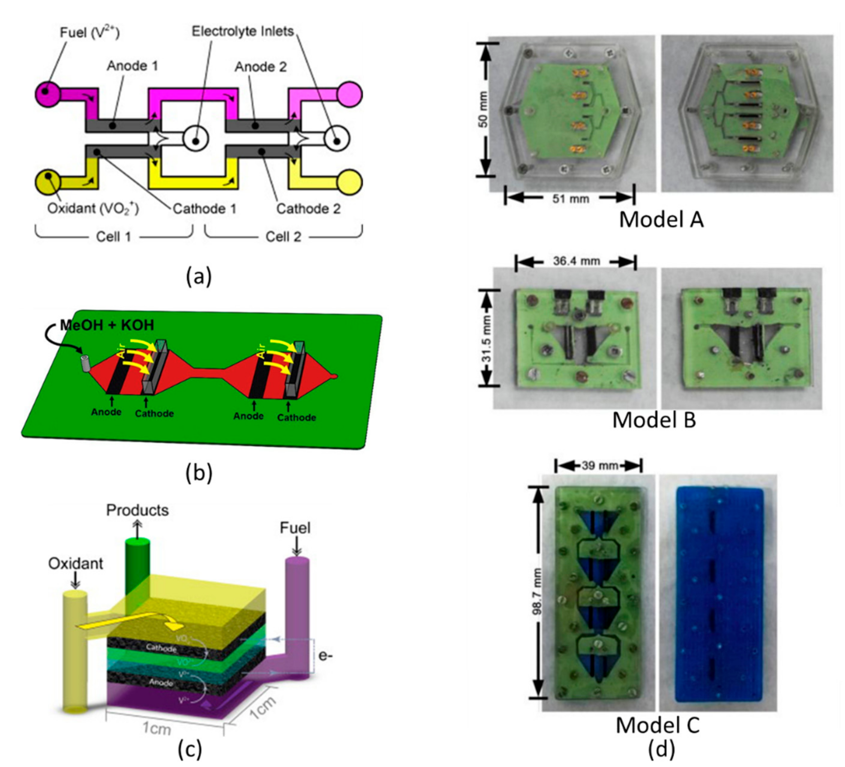
Table 2. Salloum and Posner [
169] stacked MMFCs for the first time to reuse unreacted reactants from the first cell in subsequent cells connected in parallel, as shown in
Figure 12a. They used vanadium redox species as the fuel and oxidant and added an extra electrolyte stream to keep them separated. When cells were connected in parallel, the efficiency, fuel utilization, and peak power density nearly doubled.
Cohen et al. [
54] designed a two-cell MMFC stack using dissolved oxygen and formic acid as the oxidant and fuel, respectively. A maximum power of 118 μW was produced, which was 2.6 times higher than that of a single cell. Ho and Kjeang [
132] developed a two-cell vanadium MMFC stack with two inlet flow configurations: symmetric bilateral inlets and nonsymmetrical unilateral inlets. The former attained better performance owing to its symmetrical and uniform flow structure. The stack produced a maximum power density of 1206 mWcm
−2, which was 2.2 times higher than that of a single cell.
Wang et al. [
62] established a four-cell MMFC stack with dissolved oxygen as the oxidant and formic acid as fuel. They examined the stack performance to find desirable conditions. Two serpentine distributers were employed to distribute the anolyte and catholyte flow evenly into four branches. This stack had 3.72 times higher peak power density when coupled in parallel, and 3.3 times higher peak power density when coupled in series than a single cell.
Abrego-Martinez et al. [
170] proposed a two-cell MMFC stack that works with mixed reactants (5 M methanol in KOH), as shown in
Figure 12b. They doubled the OCV in comparison with a conventional MMFC. Lee and Ahn [
125] developed an MMFC planar single stack using multiple laminar flows in a single channel. The single stacks were connected in parallel or serial. They found that such single stacks produced higher power output than arrayed structures.
Moore et al. [
119] developed a plate-frame MMFC architecture with porous electrodes, as shown in
Figure 12c. The architecture enabled vertical stacking by using radial flow-through porous electrodes and produced a maximum power density of 5.8 mWcm
−2. Moreno-Zuria et al. [
171] designed three different models of MMFC stacks that could reuse fuel, as shown in
Figure 12d. They investigated MMFC stack models in series, parallel, or combinations of series and parallel. They used low-concentration fuel (0.25 M formic acid), and oxygen was used as the oxidant. The power density was 83 mWcm
−2, and the current density was 345 mAcm
−2 for a model connected in parallel.
Wang and Leung [
83] demonstrated an MMFC stack comprising six cells connected in series and fed with aluminum. Electrolyte was reused after passing through a single cell for hydrogen formation. When operated at room temperature, the stack produced a peak power of 531 mW and current of 248 mA with an OCV of 6 V.
8. Challenges and Prospective Studies
The articles published since 2002 have cemented the foundation for the commercialization of MMFCs. Recently, extensive accomplishments have been made in the areas of unconventional reactants [
113,
191,
193,
195,
196], catalysts [
197,
198,
199,
200,
201], electrode configurations [
92,
119,
188,
202,
203], electrode materials [
107,
117,
190,
204,
205,
206], and MMFC architectures [
54,
61,
78,
207,
208,
209,
210]. Key challenges and major issues must be addressed to benefit from the advantages of MMFCs as a long-lasting power source.
Table 5 gives insight into the development of future MMFCs with higher power density and fuel utilization.
The performance of MMFCs is primarily restricted by the slower mass-transportation to the electrodes and lower oxidant’s concentration and solubility in the cathodic reaction [
33,
56]. The MMFC with air-breathing cathode lets oxygen transport from the ambient air continuously, which enhances the diffusivity and provides uniform concentration in comparison with dissolved oxygen provided in flow-over or flow-through cathode architecture. However, the air-breathing architecture decreases the probability of scaling up by stacking units of MMFCs [
78]. However, multi-stream CLFMMFCs can be investigated by employing air-breathing electrodes at both ends and placing flow-through electrodes with selective catalysis to avoid fuel reacting at cathode and causing mixed potential.
In counter-flow MMFCs, the fuel and oxidant are kept isolated by inserting an electrolytic stream during their residence time in the fuel cell, do not blend or fuse diffusively, and they are collected distinctly. Thus, the reactants can be recirculated to enhance the fuel utilization and power density. Sequential RFMMFC configurations remove linear diffusion along the length. Nevertheless, there is a possibility that in the sequential RFMMFCs, fuel may crossover and react at cathode causing mixed potential. Salloum et al. [
62] proposed careful tuning of flow rate and selective catalysis to avoid fuel reacting at cathode. However, a sequential RFMMFC configuration with an additional electrolytic stream (multi-stream) can be studied prospectively, the fuel and oxidant pass through porous disc-shaped electrodes and avoid forming a diffusive interfacial zone due to the electrolytic stream, which ensures minimum fuel crossover with significant fuel utilization. Furthermore, the fuel and oxidant streams can be collected distinctly at the outlet and recirculated. A multi-stream OFMMFC can be developed by inserting multiple orthogonal electrolytic streams to enhance the performance of the fuel cell.
The highest power density to date in MMFCs was achieved by using vanadium redox species (
/
) as the fuel and oxidant. The (
/
) couple ensures rapid diffusion and species transport, as well as uniform reaction rates. The OCV (1.5 V) achieved by the vanadium redox couple is higher than those of other fuel and oxidant combinations (e.g., formic acid coupled with different oxidants). Additionally, the vanadium redox species can react with bare carbon electrodes without any catalyst. Among unconventional fuels, Al is abundantly available, light-weight, cost-efficient, eco-friendly, and recyclable, which makes it a very appropriate choice as an “indirect fuel” in hydrogen-based MMFCs. Additionally, as an alkaline catalyst, Al reacts spontaneously and vigorously, resulting in excess H
2 for MMFC operation [
83]. Thus, it can be effectively used in next-generation MMFCs.
The major factors that limit the performance of MMFCs can be solved by using a suitable flow configuration with an improved electrode architecture that can be used in stacked units of MMFCs. The residence time and removal of depleted region over the surface of electrodes can be resolved by placing lateral paper-based strips over a selective area of electrode to advect the depletion region downstream. Commercialization of MMFCs can be made possible by: (i) mushrooming performance of MMFCs (e.g., by stacking multiple unit MMFCs), (ii) minimizing crossover issues (e.g., by using a counter-flow or radial-flow configuration with an additional electrolytic stream), (iii) enhancing fuel utilization (e.g., by using flow-through anodes and dual pass/recirculation), (iv) minimizing mass-transport losses (e.g., by implementing air-breathing cathodes), and (v) implementing a fuel-oxidant couple with better OCV and electrochemical kinetics.
9. Applications
Although MMFCs have enormous potential, their applications as a power source are delimited due to the lower performance linked with two key limitations: (i) the fuel and oxidant streams are laminar, which occurs in microchannels, and (ii) intrinsic design constrictions. The power output from a single MMFC is insufficient for commercial applications. Hence, numerous MMFC units are stacked in series or parallel with any of the aforementioned reactants’ flow configurations to reach sufficient power for practical applicability. MMFCs can be combined directly with lab-on-chip devices (on-chip applications). Devices employed for biological and environmental sampling, motion sensors, wireless sensors, and detection, can be directly powered by MMFCs.
The on-chip applications may have low- or high-power demands [
155]. To fulfil the energy requirements of both power modes in such devices, an MMFC can energize a secondary battery by functioning continuously. Abrego-Martinez et al. [
170] designed a MMFC stack with two cells that can produce the power to run low-power applications, such as micro analytical systems, blood diagnostics, DNA analysis devices, and LEDs [
211]. Gurrola et al. [
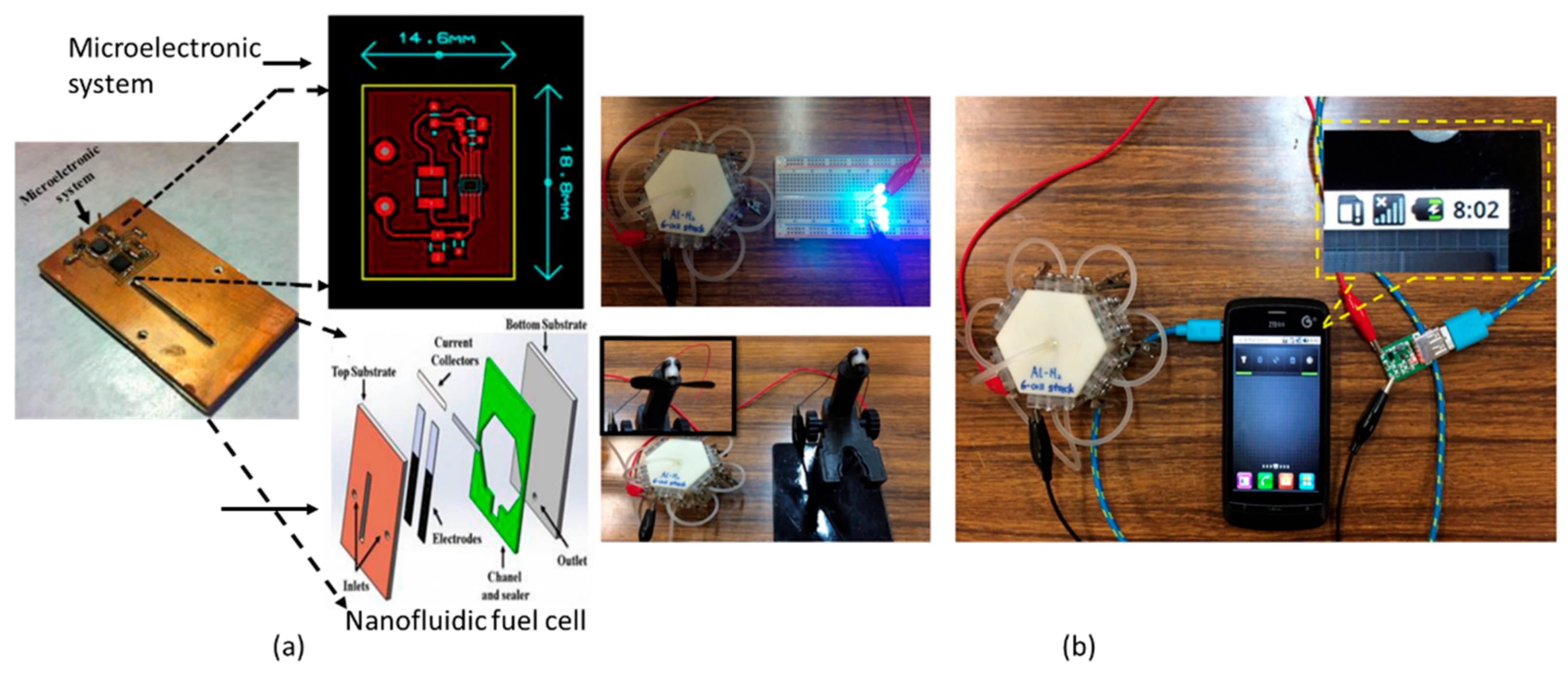
212] developed a membraneless nano-fluidic fuel cell using fiberglass as substrate and electrodes with flow-through architecture. They coupled their power source with a microelectronic interface (
Figure 15a) and analyzed it for functioning lower power devices, such as LEDs.
Wang and Leung [
83] designed a novel MMFC stack fed with aluminum. They illustrated the practical applicability of the stack by charging a cell phone, driving an electric fan, and lighting LEDs, as shown in
Figure 15b. LFMMFCs are being extensively used commercially for micro devices, such as commercial glucometers [
67,
68] and self-powered sensors [
71]. They are applied to efficiently separate analytes by a paper-based channel [
72,
75] and to detect lake water, human serum samples [
69], and pentachlorophenol in real samples [
74]. They also have point-of-care applications [
155]. Dector et al. [
165] developed a paper-based LFMMFC that uses blood as fuel to investigate HIV AIDS.
The practical applicability of MMFCs and commercialization are dependent on the improvement in the performance (i.e., peak power density and fuel utilization) at low flow rates of reactant streams in a unit of MMFC, which enhances the maximum reachable power density when unit cells are stacked together. To accomplish higher power density, reactants transportation and electrochemical kinetics should be upgraded. For lower flow rates of fuel and oxidant, crossover turns out to be substantial, resulting in a thicker mixing region. The electrodes with flow-through architecture in combination with new flow configurations could provide a way to improved fuel utilization and power density. Additionally, by enhancing the fuel utilization, the fuel concentration at the interface of the co-laminar flow would be decreased, and fuel crossover would be alleviated. The electrodes with better architecture and design can be constructed using microfabrication techniques to increase the rate of the electrochemical reactions by enhancing the reactive surface area. However, this process could increase the total fabrication cost.
MMFCs are an attractive alternative due to their functioning at room temperature, lower manufacturing cost, and flexible material selection. However, there are still several complications affecting commercialization, i.e., obligatory electric pumping, complex water system, lower portability owing to stable workstation, and stacking complications. To resolve these issues, great efforts have been made to boost the performance by (i) improving microchannel design, (ii) improving electrode architecture by continuous development of fuel-tolerant cathodes for different fuels, (iii) replacing electric pumping with passive pumping, and (iv) enhancing MMFC stability in portable applications employing an extra porous separator at fuel-oxidant interface. The channel thickness can be reduced to reduce ohmic resistance to the passage of ions. As for real applications, currently, the paper-based MMFCs are being employed in market for biosensors and point-of-care devices.


