Article

Application of Phase Change Material and Artificial Neural Networks for Smoothing of Heat Flux Fluctuations

Department of Energy Conversion Engineering, Mechanical and Power Engineering Faculty, Wrocław University of Science and Technology, 50-370 Wrocław, Poland
*
Author to whom correspondence should be addressed.
Energies 2021, 14(12), 3531; https://doi.org/10.3390/en14123531
Submission received: 30 April 2021 / Revised: 1 June 2021 / Accepted: 9 June 2021 / Published: 14 June 2021
(This article belongs to the Special Issue Energy Storage, Energy Conversion, and Multifunctional Materials)

Abstract

:
The paper presents an innovative method for smoothing fluctuations of heat flux, using the thermal energy storage unit (TES Unit) with phase change material and Artificial Neural Networks (ANN) control. The research was carried out on a pilot large-scale installation, of which the main component was the TES Unit with a heat capacity of 500 MJ. The main challenge was to smooth the heat flux fluctuations, resulting from variable heat source operation. For this purpose, a molten salt phase change material was used, for which melting occurs at nearly constant temperature. To enhance the smoothing effect, a classical control system based on PID controllers was supported by ANN. The TES Unit was supplied with steam at a constant temperature and variable mass flow rate, while a discharging side was cooled with water at constant mass flow rate. It was indicated that the operation of the TES Unit in the phase change temperature range allows to smooth the heat flux fluctuations by 56%. The tests have also shown that the application of artificial neural networks increases the smoothing effect by 84%.

1. Introduction

Currently, thermal energy storage (TES) technologies are being widely developed on the global scale. The demand for heat storage arises in two cases: the instability of the operation of the heat source and the variability of heat consumption. The instability of the operation on both the heat generation and heat consumption causes variation in the flow rate and/or temperature, which results in variations in the heat flux. The purpose of heat storage is to compensate for the difference between heat supply and demand [1,2,3].
Irregularity of heat source operation may be caused by several factors, e.g., the non-stationary nature of heat generation. An example of a non-stationary process is the recovery of waste heat for reuse. Other factors affecting the irregularity of the heat source operation include external conditions such as insolation, wind force and external temperature. These external factors apply to all renewable energy sources, which are dependent on the sunlight intensity, wind force, external temperature, etc. [4]. On the other hand, the variability of heat consumption is a result of variable heat demand at different periods of time, usually occurring in a daily or annual cycle.
Depending on the abovementioned factors, heat storage may be considered as short- or long-term. Long-term heat storage is most often used in case of variable heat consumption in the annual cycle and the heat storage period ranges from several weeks to several months. As the heat capacity of storage devices must be large, the heat storage materials are expected to be low cost and commercially available [5]. The most commonly used materials are water, rock, concrete and sand. In case of short-term heat storage, the energy storage time ranges from a few hours to a few days. Because of the shorter storage time, the heat capacity of the device is smaller and the unit cost of the storage material is less significant. This type of storage is commonly used in photovoltaic installations, where the storage time is usually about 12 h [4].
The amount of stored heat is proportional to the initial and final heating temperature difference as well as the specific heat of the storage material. This heat capacity is called sensible heat [6,7,8]. This feature is an important limitation of the heat capacity of the materials, in which heat storage is achieved only by increasing their temperature. The heat capacity may be increased by phase change of the heat storage material. In this case, the heat capacity is elevated by the value of latent heat [9,10,11]. In most cases, liquid to solid phase transformation (or vice versa) is used. Two advantages of phase transformation of heat storage material can be mentioned. The first one is the increased heat storage density compared to sensible heat storage materials. The second advantage is a constant phase-change temperature, which stabilizes the heat flux on both the charging and discharging side.

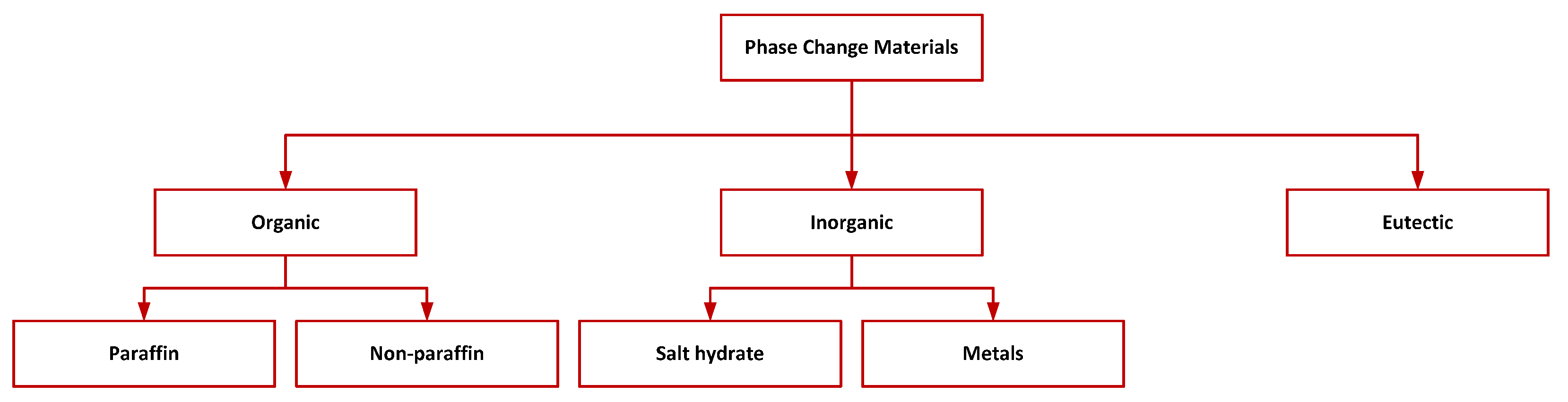
1.1. Classification and Properties of PCMs

Phase change materials (PCMs) can be classified as organic compounds, inorganic compounds and eutectic mixtures (Figure 1). Organic PCMs include paraffins and other materials; inorganic PCMs include hydrated salts and metals. The last classification includes organic and inorganic eutectic mixtures. One paper [5] provided extensive databases of different materials used in heat storage. The MatWeb website was identified as the database containing the most materials, including their thermophysical properties and applications.
One paper [5] describes in detail the criteria of PCM selection. The selection of PCM is determined by six basic principles related to the thermal, physical, chemical, technical, dynamic and economic properties.
  • Thermal properties:
    Matching phase transformation temperature of PCM with the temperature of the process in which it is to be used.
    Large specific heat determining the amount of stored sensible heat at the same temperature difference.
    Large phase transition enthalpy determining the amount of stored latent heat at the same phase transition temperature. Sensible and specific heat affects the density of heat stored in PCM.
    Large heat transfer coefficient between PCM and the heat transfer fluid. This coefficient depends on thermal conductivities of PCM, the fluid and the structural elements of the TES Unit. Its high value influences the charging and discharging rate of the TES Unit.
    Congruent melting means that PCM must have a consistent chemical composition in different phase states. This prevents phase separation phenomena caused by density differences between solid and liquid states.
  • Physical Properties:
    Phase transformation equilibrium, causing the phase transformation process to be de-reversible and only temperature dependent.
    Low vapor pressure, meaning that PCM will not completely evaporate at operating temperature.
    High density of PCM determines high ratio of stored heat per unit volume of PCM.
    Small volume change with phase transition. The reduction in volume when PCM solidifies can lead to a smaller heat transfer field, which in turn worsens heat transfer. In pressurized storage tanks, a large volume change of PCM leads to a pressure increase, which has to be considered in the design of a storage tank and increases its cost.
  • Dynamics:
    Possibly low overcooling phenomenon and no supersaturation phenomenon during melting,
    Fast crystallization of PCM, which means fast exothermic reaction. This affects the dynamics of the charge/discharge process.
  • Chemical properties:
    Chemical stability during the repeated charging/discharging process; there should be no segregation, chemical decomposition of PCM and other phenomena causing a change of PCM properties. This affects the maintenance of the TES Unit performance over a long period of time and increases its durability and reliability.
    Absence or low corrosivity means that PCM and TES Unit construction material do not enter into chemical reactions with each other, which leads to a lack of degradation of both PCM and the construction material. This has the effect of increasing the durability and reliability of the TES Unit.
    PCM should be non-toxic, non-flammable, non-explosive and safe to use and have the least environmental impact.
  • Economics:
    PCM should be easily available and cheap.
  • Technical requirements
    PCM should be checked in industrial conditions, should guarantee high reliability and should provide the smallest possible TES Unit size.
The abovementioned six basic principles are essential in the design of thermal energy storage systems and materials selection. In practical applications, it is difficult to select a PCM which matches all abovementioned principles. However, some of the properties may be considered as primary, such as the phase change temperature, latent heat, thermal stability, high thermal conductivity and low corrosivity. In this paper, the presented criteria were used to select the optimal PCM.

1.2. Applications of PCMs

A large variety of applications of PCMs for energy storage has been discussed, e.g., in buildings, automotive and refrigeration [12].
One of the more commonly used organic PCMs are paraffins. Paraffins have a wide range of phase transformation temperatures (from −182 °C to 135 °C) and the heat of phase transformation is 180 J/g to 230 J/g [13,14]. Due to their good properties and low price, they have found applications in many fields. In [15], the application of PCMs to reduce the energy consumption in a building is described. Octadecane paraffin and an organic material (BioPCM) were used. Paraffins are often used in solar energy systems. In [16], a novel system consisting of a trough solar collector heating PCM through a heat pipe is described. Paraffin wax with a melting point in the range of 57–61 °C was used as a PCM. The use of a finned surface in PCM was found to improve heat transfer, resulting in shorter charging/discharging times for the system. In [17], RT50 paraffin (melting point 50 °C) was used in a solar hot water generation system. PCM was located in a pipe-in-pipe heat exchanger. Based on numerical calculations, the heat flux stability of PCM located in the inner pipe was found to be better. In addition, the melting time was reduced by almost 50% by the special arrangement of the phase change material.
Other organic materials found in heat storage are fatty acids [18,19], alcohols [20], esters [21,22] and polymers [23]. Advantages of these materials include non-corrosivity, poor susceptibility to subcooling and good thermal and chemical stability. Disadvantages include low enthalpy of phase transformation, poor heat conduction and flammability [19,22].
Inorganic PCMs can be divided into four types: hydrated salts, molten soles, metals and alloys. An overview of hydrated salts currently used for heat storage and their thermophysical properties is given in [24]. Hydrated salts are characterized by the high density of stored heat, low price, lack of toxicity and non-flammability. The disadvantages of hydrated salts include leakage during phase transition [25], overcooling [26], phase separation [23] and low thermal conductivity [27]. Despite the mentioned disadvantages, hydrated salts have found applications in water sub-heating and space heating systems. In [27], the heat storage density obtained using modified sodium acetate trihydrate was 2.5 times higher than in traditional water tanks. The thermophysical properties of 125 hydrated salts are reported in [28]. The properties were obtained from thermogravimetry analysis (TGA) and differential calorimetry analysis (DSC). However, not all the described hydrated salts could be used as PCMs; more than 80% of the salts did not meet the conditions to be used in TES systems.
Due to their properties, molten salts have become very popular in heat storage systems in recent years. The advantages of molten salts include a wide range of phase transition temperatures; good thermal conductivity; high density of stored heat; no undesired exothermic chemical reaction; good thermal stability at high temperatures; non-toxicity; and low price. In [29], the thermophysical properties of selected salts with melting points in the range of 100–400 °C for liquid energy storage applications were compiled. Experimental studies of the properties of salts with melting temperatures below 200 °C were carried out. A composition of 16 new salts was proposed and their properties were experimentally measured.
In the work [30], six new salts were proposed for concentrated solar power applications and operating temperatures in the range of 300–600 °C. The thermophysical properties and stability of the six materials were investigated. The phase transition temperature, phase transition enthalpy and specific heat were measured using a differential scanning calorimeter. The materials studied were inorganic eutectic PCMs, four based on carbonate salts (Na2CO3, K2CO3 and Li2CO3) and two based on chloride salts (NaCl, MgCl2 and KCl). It was emphasized that the thermophysical properties of PCMs such as phase transition temperature, phase transition enthalpy and specific heat are usually calculated and discrepant with the results obtained from measurements.
A new innovative salt, NaCl-NaF-Na2CO3, is presented in [31], of which the thermophysical properties were determined experimentally. This salt is dedicated to the application in concentrated solar systems. The undoubted advantage of this salt is its low price, which is about 35% lower than the price of NaNO3-KNO3 salt commonly used in solar systems. [32]. The salt is also thermally stable up to 750 °C, and even up to 800 °C during short periods of operation.
The authors of the paper [33] studied the application of three popular salts in solar systems for energy storage in solar power plants. These are salts are: Hitec (40% NaNO2-7% NaNO3-53% KNO3), HitecXL (48% Ca (NO3) 2-45% KNO3-7% NaNO3), Solar Salt (40% KNO3-60% NaNO3). Hitec salt was used in the solar power plants Eurelios Station in Italy and CESA-1 in Spain [34]. Solar Salt has been used in the Spanish Andasol, Solar Tres and Solar Two Station solar power plants in the USA [35,36,37]. Salts are also used as a heat transfer fluid. An example is the Italian energy company ENEL, which built a 5 MW Archimede solar power plant in Priolo Gargallo near Syracuse, Sicily, Italy. The power plant uses Solar Salt simultaneously as heat storage material and as HTF [38,39].
The paper [40] focuses on a review of the state of the art regarding the use of shell- and-tube storage tanks filled with molten pure salts and salt mixtures for heat storage. Due to simple design of such devices, they are popular in commercial and industrial heat storage systems. A disadvantage of shell-and-tube storage tanks is the poor thermal conductivity associated with the tank design and the thermophysical properties of the salts. This paper reviews various techniques to improve heat transfer.
Metals and alloys as heat carrier and heat storage material are used for medium to high temperatures. The paper [41] reviews recent research advances in latent and thermochemical heat storage at medium and high temperatures using metals and metal compounds. Metals and metal alloys used as PCMs are characterized by high density of stored heat, high thermal conductivity, good stability, low subcooling, low vapor pressure and small volume change [42]. A major limitation in the use of these materials is their high corrosivity, increasing with temperature, and high cost. The most commonly used PCMs include Al, Cu, Fe, Mg, Zn and their alloys. Attempts are being made to use these PCMs in solar power plants and industrial waste heat recovery systems. In [43], a magnesium-zinc alloy was used as PCM and laboratory scale tests were carried out. The TES Unit consisted of two concentric pipes with a metal alloy between them. Synthetic oil was used as HTF. No overcooling effect was observed, melting and solidification temperature was 342 °C. Experimental results were compared with those obtained from CFD numerical modeling. It was found that a limiting factor of heat transfer is the oil inside the pipe and not the thermal permeability of metal PCM. The use of a two-phase fluid as HTF was proposed as a solution to this problem.
The use of phase change material reduces the fluctuation of heat flux on the heat source side. However, in industrial thermal plants, automation systems are additionally used to stabilize the heat transfer process. These systems usually operate based on traditional PID-type controllers, but artificial neural networks (ANNs) are increasingly used for this purpose [44,45,46,47,48,49,50,51].
ANNs are used for performance prediction in nonlinear systems with many inputs. ANN consists of processing elements called neurons, which can be thought of as a nonlinear mathematical function. Each neuron is connected to other neurons through directed communication links with specific weights. The weights represent the information used by the network to solve problems. The weights of each communication link are given by learning the network. Each neuron applies an activation or transfer function to its input, which is the sum of the weighted input signals to obtain the output signal [51]. Historical data (off-line) or measured data (on-line) are used to learn the neural network. Based on the historical data, ANN is able to predict selected parameters of the heat storage system. In industrial applications, ANNs are usually a master layer that changes the settings of PID controllers.
In [46], ANN was used to predict the porosity of a metal foam located in PCM. In [47], the heat transfer from PCM (RT42 paraffin) to a heat sink made of aluminum was experimentally studied. ANN was used to predict the Nusselt number during PCM melting. The maximum difference between experimental and ANN predicted data was less than 6.0%. ANNs have also been used in solar power plants. In [49], ANN was used in a solar thermal system for domestic hot water generation and space heating. ANN predicted the stratification temperature in a hot water tank with average relative errors of 1.09–1.18%. ANNs are quite commonly used in photovoltaic systems [49,52,53,54,55].
The aim of the study was to smooth the heat flux fluctuations, resulting from a variable heat source operation. For this purpose, a Hitec eutectic salt phase change material was used, which melts at a nearly constant temperature. While Hitec salt was used as HTF in solar plants [34], there is no literature information concerning application of Hitec salt as PCM for large-scale energy storage.
In the large-scale industrial applications of energy storage systems, PID-based control systems are commonly used. The most significant drawback of PID controllers is their poor performance in the control of nonlinear and unpredictable processes. This problem may be solved by the use of ANN, which allows to enhance the control quality in case of the abovementioned processes. However, large-scale application of energy storage systems with ANN control has not been sufficiently studied in the literature.
To enhance the smoothing effect, a classical control system based on PID controllers was supported by ANN. The TES Unit was supplied with steam at a constant temperature and variable mass stream, while a discharging side was cooled with water at a constant mass flow rate.

2. Materials and Methods

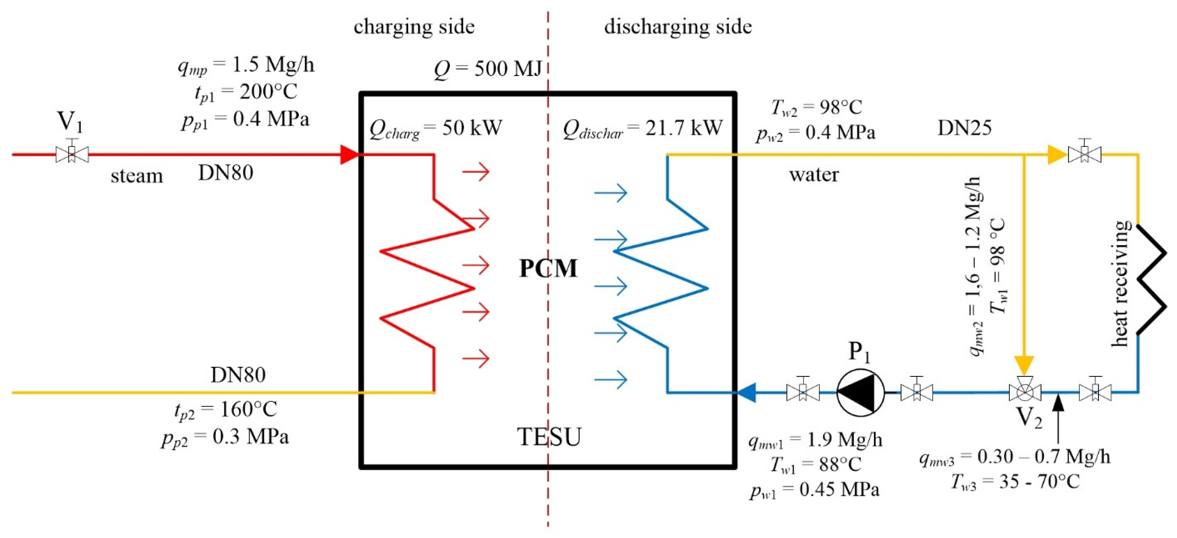
2.1. Description of TES Installation

To perform the study, a pilot installation was built, the main component of which was a TES Unit filled with PCM. The aim of the installation was to check the possibility of supplying the absorption chiller (AbCh) with the heat from the TES Unit under the conditions of variable heat flux on its charging side, as well as under the conditions of non-charging of the TES Unit.
Figure 2 shows a schematic of the installation with thermal and flow parameters marked at key points. The TES Unit was charged by 200 °C, 0.4 MPa steam supplied by a combined heat and power plant. Maximum mass flow rate of the steam was equal to 1.5 Mg/h. The mass flow rate of steam supplying the TES Unit was controlled by valve V1, while the mass flow rate of cooling water on the discharging side, was controlled by varying the speed of pump P1. The heat received from the TES Unit was directed to the district heating network. Due to the requirements of AbCh, the water temperature at the inlet and outlet of TES Unit had to have a constant value of 98 °C and 88 °C, respectively. For this reason, an additional mixing node was installed on the discharging side.
Both charging and discharging pipes type P245GH [56] were made of SS316L stainless steel. The pipes were insulated with mineral wool with a thermal conductivity of 0.047–0.500 W/mK (at 100 °C). NOCCHI DHR 2–50 T, with parameters qV = 3.0 m3/h, H = 12 m, P = 0.5 kW, was used as the P1 water pump.

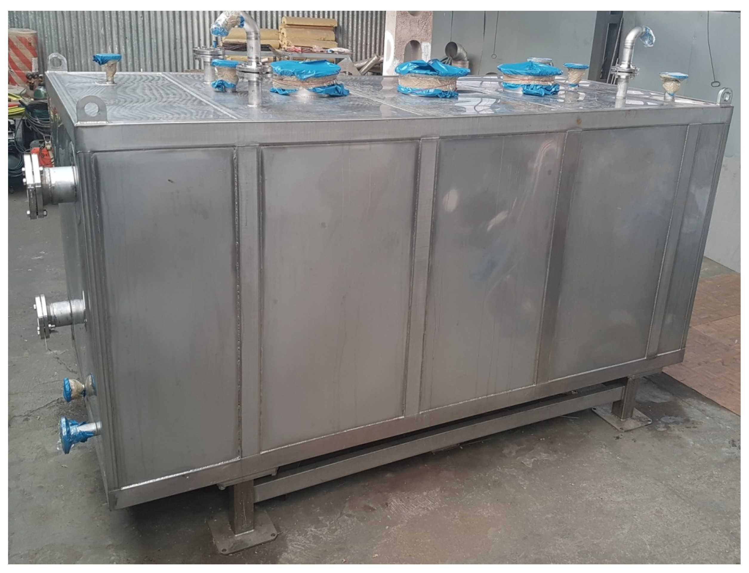
2.2. Description of the TES Unit

The TES Unit was constructed from a 2630 × 1028 × 950 mm container, filled with PCM (Figure 3). Inside the container, there were two separate sets of charging and discharging pipes, immersed in the PCM. This design solution prevented the mixing of charging HTF and discharging HTF. In order to improve the heat transfer, fins were placed on the charging pipes. The charging pipes were made in a U-shape to compensate for thermal expansion. Figure 4 shows a view of the charging and discharging side pipes of the TES Unit.
For the construction of the TES Unit, materials made of SS316L stainless steel [57] were used, and the inner pipes and tank body were made of this steel.
The selected PCM was the Hitec salt mixture [33,34,58,59] with a mass composition of 53% potassium nitrate KNO3, 40% sodium nitrite NaNO2 and 7% sodium nitrate NaNO3. This salt has been tested in practice and has excellent thermophysical properties, as well as being non-toxic and safe for humans. The thermophysical properties of the salt mixture were determined using a differential calorimetry (DSC) [60,61] and thermogravimetry (TGA) [62,63] with a NETZSCH STA 449 Jupiter thermal analyzer. The obtained measurement results indicated that the salt properties deviate to some extent from the literature data. In [33,59,64], the melting point was given as 142 °C, whereas the one obtained from measurements was 150 °C. The enthalpy of the phase transformation reported in [59] was 80 kJ/kg, while that obtained from measurements was 122 kJ/kg, which increased the heat capacity of TES Unit by about 50% at the same volume of PCM. This confirms the thesis of [30]: in real applications the properties of PCM obtained from measurements should be used because of discrepancies with calculated data. For the measured enthalpy of the phase transition, the heat capacity of the TES Unit was about 500 MJ.

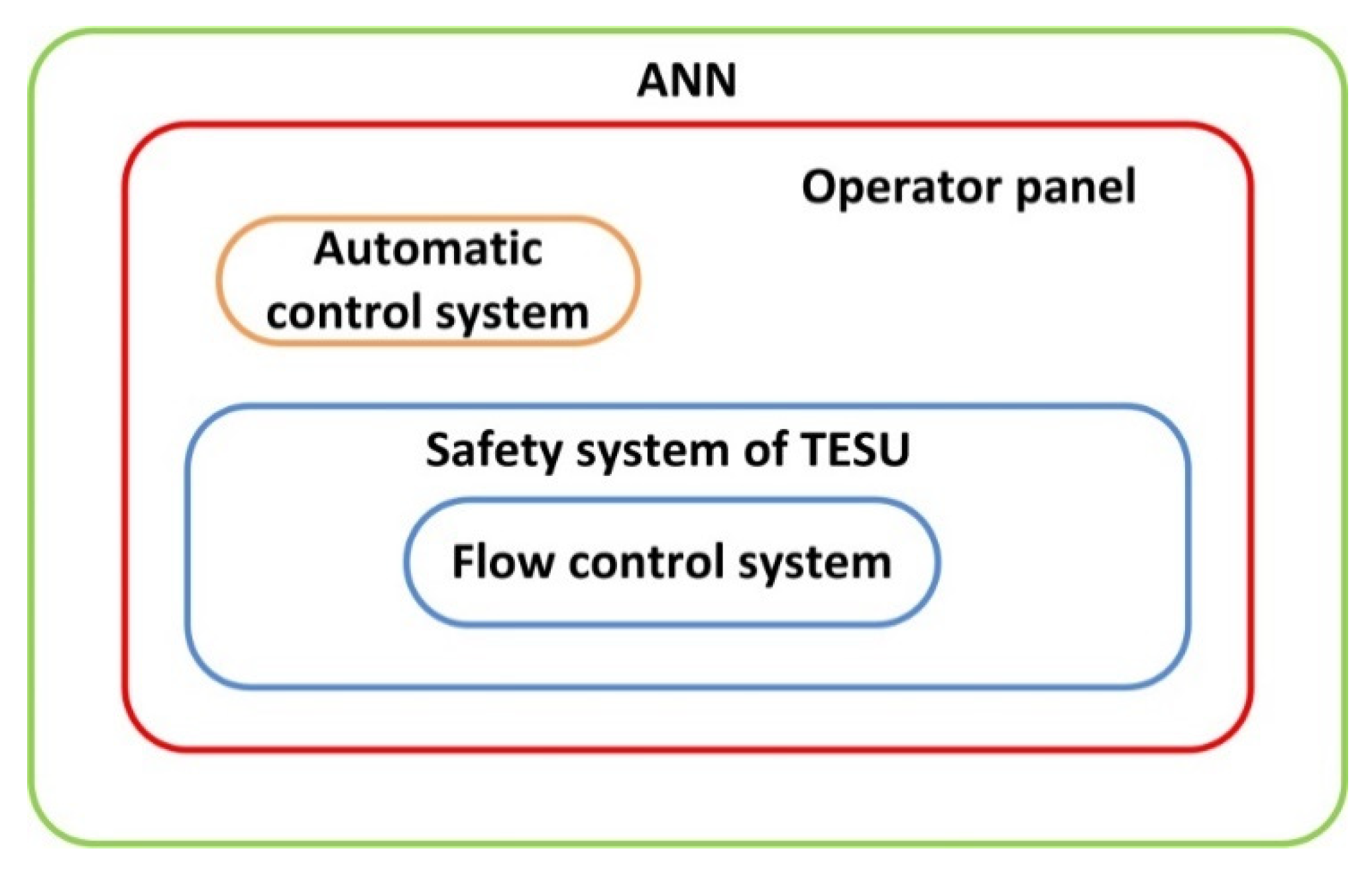
2.3. Description of the Control System with ANN

Figure 5 represents following layers of the steam and water flow control system. The ANN is the layer overriding the operator panel, safety system and flow control system.
The main loop of the program is responsible for the control of the controller state. The control algorithm includes three steps: controller state update, control of the measured values that were exceeded in the TES Unit and the control output on the system actuators (valves, inverter). The ANN communication block gathers data from the measurement system and adjusts the settings of the PID controllers.
Flow meters for measuring steam and water volume flows, temperature and pressure sensors were placed in the system on the charging and discharging side. Moreover, inside the TES Unit, the temperature sensors were placed at selected points to measure the temperature distribution. Figure 6 shows a schematic of the TES measurement system.
The steam flow rate on the charging side was measured with a Vortex type flow meter with an accuracy of <±0.5% of the measured value. An ultrasonic flowmeter with an accuracy of <±1% of the measured value was used to measure the water flow rate on the charging side. Temperature measurements were made using class B resistance temperature sensors with an accuracy of ±0.3%. Water and steam pressures were measured using a piezoresistive pressure transducer with an accuracy of ±0.3%.
A classical control system based on PID controllers implemented in a Siemens S7-1200 PLC was used to control the TES pilot installation. The system consisted of four control systems: steam mass flow rate control system, outlet water temperature control system, inlet water temperature control system and water pressure stabilization system. The task of the steam flow control system was to provide a variable mass flow with the set characteristics at the inlet to TES Unit. The outlet water temperature control system maintained a constant temperature by varying the mass flow rate of water flowing through the TES Unit. The inlet water temperature control system maintained a constant temperature by varying the degree of mixing of hot and cooled water. On the other hand, the water pressure stabilization system prevented the pressure on the d side from decreasing so that water evaporation did not occur.

2.4. Implementation of ANN

Due to the high variability of the mass flow rate of the charging steam and, thus, the controlling operating conditions of the installation, an overriding layer based on artificial neural networks (ANN) was used for control. Two applications of artificial neural networks were proposed for the TES installation: as a predictor of the outlet water temperature of the TES Unit and as a predictor of the charge state of the TES Unit. A recurrent neural network [65], along with the predictive controller, was implemented in a Siemens PM1207 PLC.
The ANN type selection has been restricted by the technical possibility of simple and direct implementation in the PLC controller and the possibility of operation with the classic PID controller. Due to the industrial-scale application of the TES installation, high stability and reliability of the controller is required. For this reason, Smith’s predictor [66,67,68,69] has been selected, as a simple and well-established solution.
Due to the accurate prediction of outlet water temperature values by the ANN, the controller is able to respond faster to the variable charging heat flux. This is essential in case of dynamic and irregular charging heat flux variations.
The structure of the ANN is composed of three layers: a hidden layer, an input layer and an output layer. The hidden layer is used for computing the weighted sum of parameters from the input layer, which is being transformed using a nonlinear sigmoid transition function [70,71]. The hidden layer contains six neurons.
In order to predict the TES Unit charge state, the input data involved: supplied heat, discharged heat and PCM temperature. The applied ANN was composed of 32 neurons in the input layer: the water inlet and outlet temperature, the water flow rate and the temperature in the bottom and top layers of PCM. The ANN output layer included the water output temperature. The prediction of the water temperature covered 30 s ahead.
The ANN training procedure has been performed using the resilient backpropagation method [72]. In total, 90% of the 6500 samples in the dataset was used for the training procedure. After the training procedure, the ANN has been tested with reference to the remaining 10% of the samples. Figure 7 represents the results of the ANN training. The horizontal axis represents the real values of the outlet water temperature from the TES Unit, while the vertical axis represents the predicted temperature values.
In case of ideal prediction, all sample points (blue) would fit the red-colored line. The results indicate that the ANN prediction quality is accurate.

2.5. Testing Methodology

Tests on the TES pilot installation consisted of setting a variable steam mass flow rate at the inlet to the TES Unit and keeping the water mass flow rate at the outlet constant. Temperatures and pressures on the charging and discharging side were measured. The value of the supply steam temperature was constant at 200 °C, while the mass flow rate varied from 0 to 1725 kg/h. The mass flow rate of water and its temperature at the inlet and outlet of the TES Unit were constant. The water flux was equal to 1800 kg/h, while the temperatures at the inlet and outlet of the TES Unit were equal to 88 °C and 98 °C, respectively.
Based on the results of the measurements of the mass flow rate, temperature and pressure, the time characteristics were plotted. The experiment was carried out by stabilizing the water temperature with traditional PID control systems and additionally with a master control system using ANN.
The specific heat of steam and water was calculated from the averaged values of temperatures and pressures between the inlet and outlet of TES Unit. The heat fluxes at the TES Unit inlet and outlet were then determined according to:
Q = qm cp ΔT,
where Q is the heat flux, cp is the specific heat and ΔT is the temperature difference between the inlet and outlet.
In order to determine the degree of heat flux smoothing, their mean standard deviations were calculated and histograms were prepared.

3. Analysis of the results

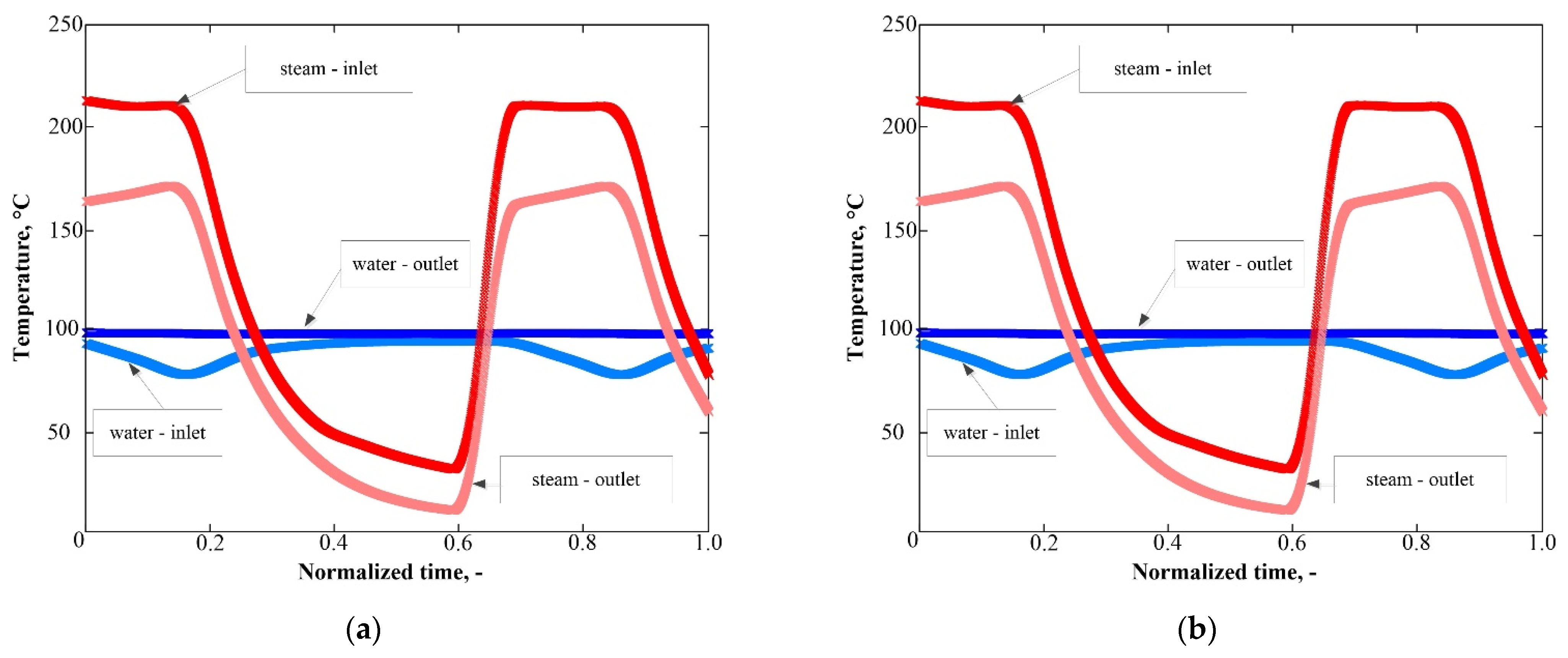
3.1. Plant Control using PID Controllers

Figure 8a shows the time-dependent characteristics of the TES Unit charge-side steam and discharge-side water temperatures during operation with only PID controllers. In all time axis plots, a normalized coordinate related to the length of the analyzed measurement series was used, which was 1039.5 min for this experiment. Figure 8b, on the other hand, shows the time characteristics of steam and water mass flow rates on the charging and discharging sides of the TES Unit, respectively. The drop in steam temperature from a value of about 200 °C below 50 °C is due to the absence of steam flow. The TES Unit at this time was not charging while a constant mass flow rate of water was discharging.
Based on the values of the mass flow rate, specific heat and temperature difference between the inlet and outlet of TES Unit, the heat flux of steam and water were calculated from Equation (1), after which the time characteristics were plotted. The characteristics were given in normalized coordinates. The steam heat flux was at its maximum value of 62 kW, while for water the heat flux varied from 7.75 kW to 41 kW.
Histograms were also plotted (Figure 9a,b), showing the number of times the heat flux value occurred within a given range of values. For plotting the histograms, the heat flux intervals were assumed to be 0.5 kW in the range of values from 0 to 65 kW.
From Figure 9a, it can be seen that the heat flux of the charging steam is distributed over the range of values from 0 to the maximum value. Due to a control method of the steam mass flow rate, the largest number of values are in the initial interval and the final intervals. On the other hand, Figure 9b shows that for cooling water, the largest number appears for a value of 7.75 kW, then decreases and ends at a value of 41 kW. The narrower range of heat flux variation is due to the operation of the TES Unit in the phase transition region, and thus, indicates the smoothing properties of PCM.

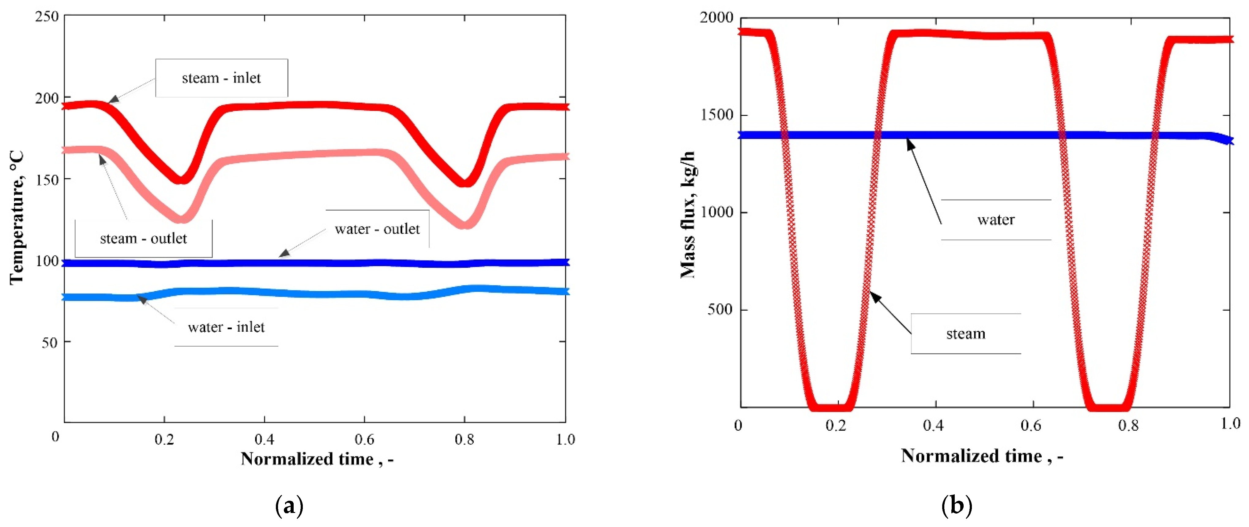
3.2. Installation Control using ANN

Figure 10a shows the time characteristics of the temperature change of the factors on the charging and discharging sides of the TES Unit for the control system using artificial neural networks. The length of the measurement series was 270 min.
As described in the previous section, the normalized time is given on the axes of all characteristics. Figure 10b shows the mass flow rate of steam and cooling water, while Figure 11b shows the normalized time characteristics of the heat flux of these factors.
From the presented characteristics, it can be seen that there are smaller fluctuations of the water heat flux when using the additional control with the superordinate layer using ANN than when using the traditional control. In Figure 12a,b, the heat flux histograms are shown, from which it can be seen that the steam heat flux is distributed over the entire range of values, while the water heat flux is distributed between 25 kW and 35 kW. This clearly indicates that the use of additional ANN control smooths the variable heat flux better.
To determine the degree of smoothing of the heat fluxes, their mean value and standard deviation were calculated for both steam and water heat fluxes (Table 1). It can be seen from Table 1 that the use of PCM and TES Unit operation in the phase transition temperature range smooths the variable heat flux. In addition, a better degree of smoothing is obtained by using control with ANN.
The charging heat flux standard deviation (Table 1) was equal to 25.5 kW, while the discharging heat flux was equal to 11.2 kW. This means that the fluctuations were reduced by 56%. The application of the ANN resulted in an enhanced smoothing effect. In case of ANN control, standard deviation of the charging heat flux was equal to 17.7 kW while the discharging heat flux was equal to 2.8 kW. This means that the fluctuations were reduced by 84%. The application of the ANN control system has a significant impact on smoothing the heat flux variations.
The observed smoothing effect results from the application of PCM, which undergoes the phase change. Melting and solidification of PCM occurs at a nearly constant temperature. Due to the constant temperature of the heat source, the temperature difference between PCM and HTF is also constant. This results in a constant heat flux. The application of ANN allows to predict the TES Unit outlet water temperature and the TES Unit charge state. This results with enhanced smoothing of the heat flux.

3.3. Uncertainty Analysis

Based on the accuracy of measuring instruments, an error in determining the heat flux of steam and water was calculated. The total differential method has been applied to determine the error, which is represented by the following equation:
ΔQ = cp ΔT Δqm + qm ΔT Δcp + qm cp Δt.
The maximum values of the relative and absolute errors of the measured and determined quantities are given in Table 2. The heat fluxes of steam and water were determined with an error smaller than 7.6%.

4. Conclusions

This paper presents an innovative method for smoothing heat flux fluctuations using the PCM thermal energy storage unit controlled by ANN. The aim of the study was to investigate the influence of the application of PCM and ANN on discharging heat flux fluctuations. The analysis involved comparing the standard deviation of charging and discharging heat flux in case of ANN and PID-only control.
The research was performed on the pilot large-scale installation. The main component was the TES Unit with a heat capacity of 500 MJ, which was charged by a variable heat flux. Hitec salt was used as the phase change material with a composition of 53% KNO3, 40% NaNO2 and 7% NaNO3. The three-layer ANN, based on sigmoid function neurons with Smith’s predictor, was used to control the installation. The training procedure was carried out using the resilient backpropagation method. The training quality was verified by comparing the predicted and real temperature values. The prediction quality was found to be accurate. The results indicate that the use of a TES Unit with PCM allows to smooth the variable heat flux.
The standard deviation of the charging heat flux was equal to 25.5 kW, while the discharging heat flux was equal to 11.2 kW, which means that the fluctuation was reduced by 56%. The application of the ANN resulted with an enhanced smoothing effect. In case of ANN control, standard deviation of the charging heat flux was equal to 17.7 kW while the discharging heat flux was equal to 2.8 kW, which means that the fluctuation was reduced by 84%. The application of ANN control system has a significant impact on smoothing the heat flux variations.
The smoothing effect of the application of PCM results from the PCM phase change. Melting and solidification of PCM occurs at a nearly constant temperature. Due to the constant temperature of the heat source, the temperature difference between PCM and HTF is also constant. This results in a constant heat flux. The application of ANN allows to predict the TES Unit outlet water temperature and the TES Unit charge state. This results in enhanced smoothing of the heat flux.

Author Contributions

Conceptualization, D.S. and T.T.; methodology, T.T.; validation, D.S. and P.S.; formal analysis, T.T.; investigation, A.S. and R.R.; data curation, D.S.; writing—original draft preparation, P.S. and T.T.; writing—review and editing, D.S.; visualization, T.T.; supervision, P.S. All authors have read and agreed to the published version of the manuscript.

Funding

This research received no external funding.

Conflicts of Interest

The authors declare no conflict of interest.

References

  1. Paria, S.; Sarhan, A.A.D.; Goodarzi, M.S.; Baradaran, S.; Rahmanian, B.; Yarmand, H.; Alavi, M.A.; Kazi, S.N.; Metselaar, H.S.C. Indoor solar thermal energy saving time with phase change material in a horizontal shell and finned-tube heat exchanger. Sci. World J. 2015, 2015, 1. [Google Scholar] [CrossRef]
  2. Safaei, M.R.; Goshayeshi, H.R.; Chaer, I. Solar Still Efficiency Enhancement by Using Graphene Oxide/Paraffin Nano-PCM. Energies 2019, 12, 2002. [Google Scholar] [CrossRef] [Green Version]
  3. Sarafraz, M.M.; Safaei, M.R.; Leon, A.S.; Tlili, I.; Alkanhal, T.A.; Tian, Z.; Goodarzi, M.; Arjomandi, M. Experimental Investigation on Thermal Performance of a PV/T-PCM (Photovoltaic/Thermal) System Cooling with a PCM and Nanofluid. Energies 2019, 12, 2572. [Google Scholar] [CrossRef] [Green Version]
  4. Vivek, C.M.; Ramkumar, P.; Srividhya, P.K.; Sivasubramanian, M. Recent strategies and trends in implanting of renewable energy sources for sustainability—A review. Mater. Today Proc. 2021. [Google Scholar] [CrossRef]
  5. Wei, G.; Wang, G.; Xu, C.; Ju, X.; Xing, L.; Du, X.; Yang, Y. Selection principles and thermophysical properties of high temperature phase change materials for thermal energy storage: A review. Renew. Sustain. Energy Rev. 2018, 81, 1771. [Google Scholar] [CrossRef]
  6. Bonamente, E.; Aquino, A. Environmental performance of innovative ground-source heat pumps with PCM Energy Storage. Energies 2020, 13, 117. [Google Scholar] [CrossRef] [Green Version]
  7. Ahmed, N.; Elfeky, K.E.; Lin, L.; Wang, Q.W. Thermal performance analysis of thermocline combined sensible-latent heat storage system using cascaded-layered PCM designs for medium temperature applications. Renew. Energy 2020, 152, 684. [Google Scholar] [CrossRef]
  8. Liu, M.; Riahi, S.; Jacob, R.; Belusko, M.; Bruno, F. Design of sensible and latent heat thermal energy storage systems for concentrated solar power plants: Thermal performance analysis. Renew. Energy 2020, 151, 1286. [Google Scholar] [CrossRef]
  9. Gage, S.; Sharan, P.; Turchi, C.; Netter, J. Evaluation of formate salt PCM’s for latent heat thermal energy storage. Energies 2021, 14, 765. [Google Scholar] [CrossRef]
  10. Elmaazouzi, Z.; El Alami, M.; Agalit, H.; Bennouna, E.G. Performance evaluation of latent heat TES system-case study: Dimensions improvements of annular fins exchanger. Energy Rep. 2020, 6, 294. [Google Scholar] [CrossRef]
  11. White, M.T.; Sayma, A.I. A new method to identify the optimal temperature of latent-heat thermal-energy storage systems for power generation from waste heat. Int. J. Heat Mass Transf. 2020, 149, 119. [Google Scholar] [CrossRef]
  12. Pielichowska, K.; Pielichowski, K. Phase change materials for thermal energy storage. Prog. Mater. Sci. 2014, 65, 67. [Google Scholar] [CrossRef]
  13. Drissia, S.; Linga, T.-C.; Hung Mo, K. Thermal efficiency and durability performances of paraffinic phase change materials with enhanced thermal conductivity—A review. Thermochim. Acta 2019, 673, 198. [Google Scholar] [CrossRef]
  14. Paroutoglou, E.; Fojan, P.; Gurevich, L.; Hultmark, G.; Afshari, A. Thermal Analysis of Organic and NanoencapsulatedElectrospun Phase Change Materials. Energies 2021, 14, 995. [Google Scholar] [CrossRef]
  15. Chung, O.; Jeong, S.-G.; Yu, S.; Kim, S. Thermal performance of organic PCMs/micronized silica composite for latent heat thermal energy storage. Energy Build. 2014, 70, 180. [Google Scholar] [CrossRef]
  16. Bhagwat, V.V.; Roy, S.; Das, B.; Shah, N.; Chowdhury, A. Performance of finned heat pipe assisted parabolic trough solar collector system under the climatic condition of North East India. Sustain. Energy Technol. Assess. 2021, 45, 101. [Google Scholar]
  17. Gorzin, M.; Hosseini, M.J.; Ranjbar, A.A.; Bahrampoury, R. Investigation of PCM loading for the energy saving of domestic hot water system. Appl. Therm. Eng. 2018, 137, 659. [Google Scholar] [CrossRef]
  18. Yuan, H.; Bai, H.; Chi, M.; Zhang, X.; Zhang, J.; Zhang, Z.; Yang, L. A Novel Encapsulation Method for Phase Change Materials with a AgBr Shell as a Thermal Energy Storage Material. Energies 2019, 12, 717. [Google Scholar] [CrossRef] [Green Version]
  19. Jebasingh, E.; Arasu, V. Characterisation and stability analysis of eutectic fatty acid as a low cost cold energy storage phase change material. J. Energy Storage 2020, 31, 101708. [Google Scholar]
  20. Veerakumar, C.; Sreekumar, A. Thermo-physical investigation and experimental unloading characteristics of lauryl alcohol as a potential phase change material for thermal management in buildings. Renew. Energy 2020, 148, 492. [Google Scholar] [CrossRef]
  21. Hegner, L.; Krimmel, S.; Ravotti, R.; Festini, D.; Worlitschek, J.; Stamatiou, A. Experimental feasibility study of a direct contact latent heat storage using an ester as a bio-based storage material. Energies 2021, 14, 511. [Google Scholar] [CrossRef]
  22. Stamatiou, A.; Obermeyer, M.; Fischer, L.J.; Schuetz, P.; Worlitschek, J. Investigation of unbranched, saturated, carboxylic esters as phase change materials. Renew. Energy 2017, 108, 401. [Google Scholar] [CrossRef]
  23. Yan, D.; Ming, W.; Liu, S.; Yin, G.; Zhang, Y.; Tang, B.; Zhang, S. Polyethylene glycol (PEG)/silicon dioxide grafted aminopropyl group and carboxylic multi-walled carbon nanopipes (SAM) composite as phase change material for light-to-heat energy conversion and storage. J. Energy Storage 2021, 36, 102428. [Google Scholar] [CrossRef]
  24. Yu, K.; Liu, Y.; Yang, Y. Review on form-stable inorganic hydrated salt phase change materials: Preparation, characterization and effect on the thermophysical properties. Appl. Energy 2021, 292, 116845. [Google Scholar] [CrossRef]
  25. Lin, Y.; Alva, G.; Fang, G. Review on thermal performances and applications of thermal energy storage systems with inorganic phase change materials. Energy 2018, 165, 685. [Google Scholar] [CrossRef]
  26. Zahir, M.H.; Mohamed, S.A.; Saidur, R.; Al-Sulaiman, F.A. Supercooling of phase-change materials and the techniques used to mitigate the phenomenon. Appl. Energy 2019, 240, 793. [Google Scholar] [CrossRef]
  27. Li, T.X.; Xu, J.X.; Wu, D.L.; He, F.; Wang, R.Z. High energy-density and power-density thermal storage prototype with hydrated salt for hot water and space heating. Appl. Energy 2019, 248, 406. [Google Scholar] [CrossRef]
  28. N’Tsoukpoe, K.E.; Schmidt, T.; Rammelberg, H.U.; Wattsa, B.A.; Ruck, W.K.L. A systematic multi-step screening of numerous salt hydrates for low temperature thermochemical energy storage. Appl. Energy 2014, 124, 1. [Google Scholar] [CrossRef]
  29. Bernagozzi, M.; Panesar, A.S.; Morgan, R. Molten salt selection methodology for medium temperature liquid air energy storage application. Appl. Energy 2019, 248, 500. [Google Scholar] [CrossRef]
  30. Liu, M.; Gomez, J.C.; Turchi, C.S.; Tay, N.H.S.; Samana, W.; Bruno, F. Determination of thermo-physical properties and stability testing of high-temperature phase-change materials for CSP applications. Sol. Energy Mater. Sol. Cells 2015, 139, 81. [Google Scholar] [CrossRef] [Green Version]
  31. Li, X.; Wu, S.; Wang, Y.; Xie, L. Experimental investigation and thermodynamic modeling of an innovative molten salt for thermal energy storage (TES). Appl. Energy 2018, 212, 516. [Google Scholar] [CrossRef]
  32. Bauer, T.; Pfleger, N.; Laing, D.; Steinmann, W.-D.; Eck, M.; Kaesche, S. High-Temperature Molten Salts for Solar Power Application. In Molten Salts Chemistry: From Lab to Applications; Elsevier: Amsterdam, The Netherlands, 2013; Chapter 20; pp. 415–438. [Google Scholar]
  33. Kearney, D.; Herrmann, U.; Nava, P.; Kelly, B.; Mahoney, R.; Pacheco, J.; Cable, R.; Potrovitza, N.; Blake, D.; Price, H. Assessment of a molten salt heat transfer fluid in a parabolic trough solar field. J. Sol. Energy Eng. 2003, 125, 170. [Google Scholar] [CrossRef] [Green Version]
  34. Yin, H.B.; Ding, J.; Yang, X.X. Heat accumulation technologies and systems for use in concentration type solar energy thermal power generation. J. Eng. Therm. Energy Power 2013, 1, 105. [Google Scholar]
  35. Herrmann, U.; Kearney, D.W. Survey of thermal energy storage for parabolic trough power plants. J. Sol. Energy Eng. 2002, 124, 145. [Google Scholar] [CrossRef] [Green Version]
  36. Dunn, R.I.; Hearps, P.J.; Wright, M.N. Molten-salt power towers: Newly commercial concentrating solar storage. Proc. IEEE 2012, 100, 504. [Google Scholar] [CrossRef]
  37. Relloso, S.; Delgado, E. Experience with molten salt thermal storage in a commercial parabolic trough plant. Andasol-1 commissioning and operation. In Proceedings of the 15th SolarPACES Conference, Berlin, Germany, 15–18 September 2009; p. 14. [Google Scholar]
  38. Moya, E.Z. 5—Innovative working fluids for parabolic trough collectors. In Advances in Concentrating Solar Thermal Research and Technology; Woodhead Publishing Series in Energy; Elsevier: Amsterdam, The Netherlands, 2017; Chapter 5; pp. 75–106. [Google Scholar]
  39. Falchetta, M.; Mazzei, D.; Russo, V.; Campanella, V.A.; Floridia, V.; Schiavo, B.; Venezia, L.; Brunatto, C.; Orlando, R. The Partanna project: A first of a kind plant based on molten salts in LFR collectors. AIP Conf. Proc. 2020, 2303, 040001. [Google Scholar] [CrossRef]
  40. Li, Q.; Li, C.; Du, Z.; Jiang, F.; Ding, Y. A review of performance investigation and enhancement of shell and tube thermal energy storage device containing molten salt based phase change materials for medium and high temperature applications. Appl. Energy 2019, 255, 113806. [Google Scholar] [CrossRef]
  41. Zhao, Y.; Zhao, C.Y.; Markides, C.N.; Wang, H.; Li, W. Medium- and high-temperature latent and thermochemical heat storage using metals and metallic compounds as heat storage media: A technical review. Appl. Energy 2020, 280, 115950. [Google Scholar] [CrossRef]
  42. Fernández, A.I.; Barreneche, C.; Belusko, M.; Segarra, M.; Bruno, F.; Cabeza, L.F. Considerations for the use of metal alloys as phase change materials for high temperature applications. Sol. Energy Mater. Sol. Cells 2017, 171, 275. [Google Scholar] [CrossRef] [Green Version]
  43. Blanco-Rodríguez, P.; Rodríguez-Aseguinolaza, J.; Gil, A.; Risueño, E.; D’Aguanno, B.; Loroño, I.; Martín, L. Experiments on a lab scale TES unit using eutectic metal alloy as PCM. Energy Procedia 2015, 69, 769. [Google Scholar] [CrossRef] [Green Version]
  44. Buffa, S.; Soppelsa, A.; Pipiciello, M.; Henze, G.; Fedrizzi, R. Fifth-generation district heating and cooling substations: Demand response with artificial neural network-based model predictive control. Energies 2020, 13, 4339. [Google Scholar] [CrossRef]
  45. Mohanraj, M.; Jayaraj, S.; Muraleedharan, C. Applications of artificial neural networks for refrigeration, air-conditioning and heat pump systems—A review. Renew. Sustain. Energy Rev. 2012, 16, 1340. [Google Scholar] [CrossRef]
  46. Duan, J.; Li, F. Transient heat transfer analysis of phase change material melting in metal foam by experimental study and artificial neural network. J. Energy Storage 2021, 33, 102160. [Google Scholar] [CrossRef]
  47. Motahar, S.; Jahangiri, M. Transient heat transfer analysis of a phase change material heat sink using experimental data and artificial neural network. Appl. Therm. Eng. 2020, 167, 114817. [Google Scholar] [CrossRef]
  48. Yaïci, W.; Entchev, E. Performance prediction of a solar thermal energy system using artificial neural networks. Appl. Therm. Eng. 2014, 73, 1348. [Google Scholar] [CrossRef]
  49. Al-Waeli, A.H.A.; Sopian, K.; Yousif, J.H.; Kazem, H.A.; Boland, J.; Chaichan, M.T. Artificial neural network modeling and analysis of photovoltaic/thermal system based on the experimental study. Energy Convers. Manag. 2019, 186, 368. [Google Scholar] [CrossRef]
  50. Wu, H.; Bagherzadeh, S.A.; D’Orazi, A.; Habibollahi, N.; Karimipour, A.; Goodarzi, M.; Bach, Q.-V. Present a new multi objective optimization statistical Pareto frontier method composed of artificial neural network and multi objective genetic algorithm to improve the pipe flow hydrodynamic and thermal properties such as pressure drop and heat transfer coefficient for non-Newtonian binary fluids. Phys. A Stat. Mech. Its Appl. 2019, 535, 122409. [Google Scholar]
  51. Fausett, L. Fundamentals of Neural Networks: Architectures, Algorithms, and Applications; Prentice Hall: Englewood Cliffs, NJ, USA, 1994. [Google Scholar]
  52. Villarrubia, G.; De Paz, J.F.; Chamoso, P.; De la Prieta, F. Artificial neural networks used in optimization problems. Neurocomputing 2018, 272, 10. [Google Scholar] [CrossRef]
  53. Rodríguez, F.; Fleetwood, A.; Galarza, A.; Fontán, L. Predicting solar energy generation through artificial neural networks using weather forecasts for microgrid control. Renew. Energy 2018, 126, 855. [Google Scholar] [CrossRef]
  54. Kalani, H.; Sardarabadi, M.; Passandideh-Fard, M. Using artificial neural network models and particle swarm optimization for manner prediction of a photovoltaic thermal nanofluid based collector. Appl. Therm. Eng. 2017, 113, 1170. [Google Scholar] [CrossRef]
  55. Yousif, J.H.; Kazem, H.A.; Boland, J. Predictive models for photovoltaic electricity production in hot weather conditions. Energies 2017, 10, 971. [Google Scholar] [CrossRef]
  56. Lazić, V.; Arsić, D.; Nikolić, R.R.; Rakić, D.; Aleksandrović, S.; Djordjević, M.; Hadzima, B. Selection and analysis of material for boiler pipes in a steam plant. Procedia Eng. 2016, 149, 216. [Google Scholar] [CrossRef] [Green Version]
  57. Parmar, V.; Kumar, A.; Prakash, G.V.; Datta, S.; Kalyanasundaram, D. Investigation, modelling and validation of material separation mechanism during fiber laser machining of medical grade titanium alloy Ti6Al4V and stainless steel SS316L. Mech. Mater. 2019, 137, 103125. [Google Scholar] [CrossRef]
  58. Xiao, X.; Jia, H.; Wen, D.; Zhao, X. Thermal performance analysis of a solar energy storage unit encapsulated with HITEC salt/copper foam/nanoparticles composite. Energy 2020, 192, 116593. [Google Scholar] [CrossRef]
  59. Lu, W.; Liu, G.; Xiong, Z.; Wu, Z.; Zhang, G. An experimental investigation of composite phase change materials of ternary nitrate and expanded graphite for medium-temperature thermal energy storage. Sol. Energy 2020, 195, 573. [Google Scholar] [CrossRef]
  60. Li, L.; Yu, H.; Wang, X.; Zheng, S. Thermal analysis of melting and freezing processes of phase change materials (PCMs) based on dynamic DSC test. Energy Build. 2016, 130, 388. [Google Scholar] [CrossRef]
  61. Jin, X.; Xu, X.; Zhang, X.; Yin, Y. Determination of PCM melting temperature range using DSC. Thermochim. Acta 2014, 595, 17. [Google Scholar] [CrossRef]
  62. Mohseni, E.; Tang, W.; Khayat, K.H.; Cui, H. Thermal performance and corrosion resistance of structural-functional concrete made with inorganic PCM. Constr. Build. Mater. 2020, 249, 118768. [Google Scholar] [CrossRef]
  63. Mohseni, E.; Tang, W.; Wang, S. Development of thermal energy storage lightweight structural cementitious composites by means of macro-encapsulated PCM. Constr. Build. Mater. 2019, 225, 182. [Google Scholar] [CrossRef]
  64. Sun, G.; Liu, Y.; Dong, S.; Wang, J. Study on novel molten salt-ceramics composite as energy storage material. J. Energy Storage 2020, 28, 101237. [Google Scholar] [CrossRef]
  65. Park, J.; Yi, D.; Ji, S. Analysis of Recurrent Neural Network and Predictions. Symmetry 2020, 12, 615. [Google Scholar] [CrossRef]
  66. Pashaei, S.; Bagheri, P. Parallel cascade control of dead time processes via fractional order controllers based on Smith predictor. ISA Trans. 2020, 98, 186. [Google Scholar] [CrossRef]
  67. Nagarsheth, S.H.; Sharma, S.N. Smith predictor embedded analytical fractional-order controller design: A delayed Bode’s ideal transfer function approach. IFAC Pap. 2020, 53, 3749. [Google Scholar] [CrossRef]
  68. Tan, K.K.; Chua, K.Y.; Zhao, S.; Yang, S.; Tham, M.T. Repetitive control approach towards automatic tuning of Smith predictor controllers. ISA Trans. 2009, 48, 16. [Google Scholar] [CrossRef]
  69. Karan, S.; Dey, C.; Mukherjee, S. Simple internal model control based modified Smith predictor for integrating time delayed processes with real-time verification. ISA Trans. 2021. [Google Scholar] [CrossRef]
  70. Lin, X.; Xi, W.; Dai, J.; Wang, C.; Wang, Y. Prediction of Slag Characteristics Based on Artificial Neural Network for Molten Gasification of Hazardous Wastes. Energies 2020, 13, 5115. [Google Scholar] [CrossRef]
  71. Langer, S. Approximating smooth functions by deep neural networks with sigmoid activation function. J. Multivar. Anal. 2021, 182, 104696. [Google Scholar] [CrossRef]
  72. Gonzalez Viejo, C.; Torrico, D.D.; Dunshea, F.R.; Fuentes, S. Development of Artificial Neural Network Models to Assess Beer Acceptability Based on Sensory Properties Using a Robotic Pourer: A Comparative Model Approach to Achieve an Artificial Intelligence System. Beverages 2019, 5, 33. [Google Scholar] [CrossRef] [Green Version]
Figure 1. General classification of PCMs.
Energies 14 03531 g001
Figure 2. Simplified schematic of the pilot scale TES plant.
Energies 14 03531 g002
Figure 3. Thermal energy storage unit.
Energies 14 03531 g003
Figure 4. U-shaped charging and discharging side pipes.
Energies 14 03531 g004
Figure 5. Steam and water control system layers.
Energies 14 03531 g005
Figure 6. Scheme of the TES measurement system.
Energies 14 03531 g006
Figure 7. Real and predicted values of the outlet water temperature from TES Unit.
Energies 14 03531 g007
Figure 8. Time characteristics: (a) temperatures of the factors on the charging and discharging side of TES Unit; (b) mass flow rate of the charging steam and cooling water.
Energies 14 03531 g008
Figure 9. Heat flux histogram: (a) charging steam; (b) cooling water.
Energies 14 03531 g009
Figure 10. Time characteristics: (a) inlet and outlet temperatures of charging steam and cooling water; (b) mass flow rate of charging steam and cooling water.
Energies 14 03531 g010
Figure 11. Normalized time characteristics of the heat flux of the charging steam and cooling water with control: (a) PID; (b) ANN.
Energies 14 03531 g011
Figure 12. Histogram of heat flux: (a) charging steam; (b) cooling water.
Energies 14 03531 g012
Table 1. Comparison of the mean values and standard deviation of smoothed heat fluxes of water and steam under PID control and with an additional prediction system.
No.FactorPID Only ControlANN Enhanced Control
Mean ValueStandard DeviationMean ValueStandard Deviation
1.Charging heat flux (steam)22.011 kW25.462 kW27.549 kW17.669 kW
2.Discharging heat flux (water)20.032 kW11.206 kW30.004 kW2.793 kW
Table 2. The estimated errors in the measurement and uncertainties of the calculated parameters.
ParametersMax Absolute ErrorMax Relative Error
Steam mass flow rate<10 kg/h±0.5%
Water mass flow rate<19 kg/h±1%
Steam temperature<3.0 °C±0.3%
Water temperature<1.2 °C±0.3%
Steam specific heat<25 kJ/kg K±0.6%
Water specific heat<25 kJ/kg K±0.6%
Charging heat flux (steam)<4.6 kW±7.5%
Discharging heat flux (water)<3.2 kW±7.6%
Publisher’s Note: MDPI stays neutral with regard to jurisdictional claims in published maps and institutional affiliations.

