Availability-Based Selection of Electricity Delivery Network in Marine Conversion Systems Using Bayesian Network
Abstract
:1. Introduction
2. Introduction on Typical Energy Network Topologies
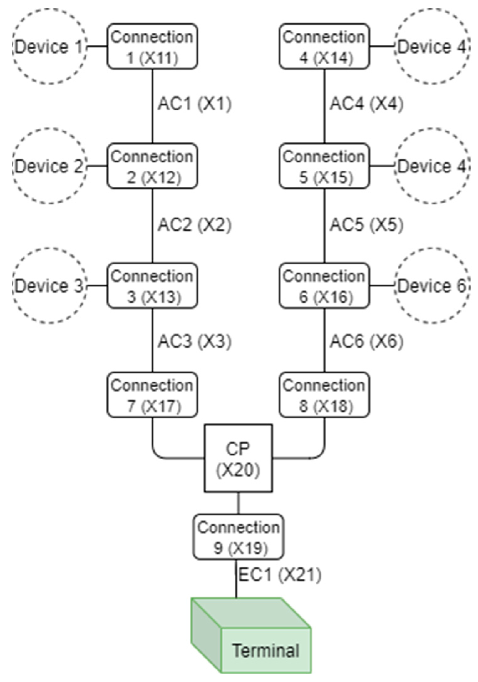
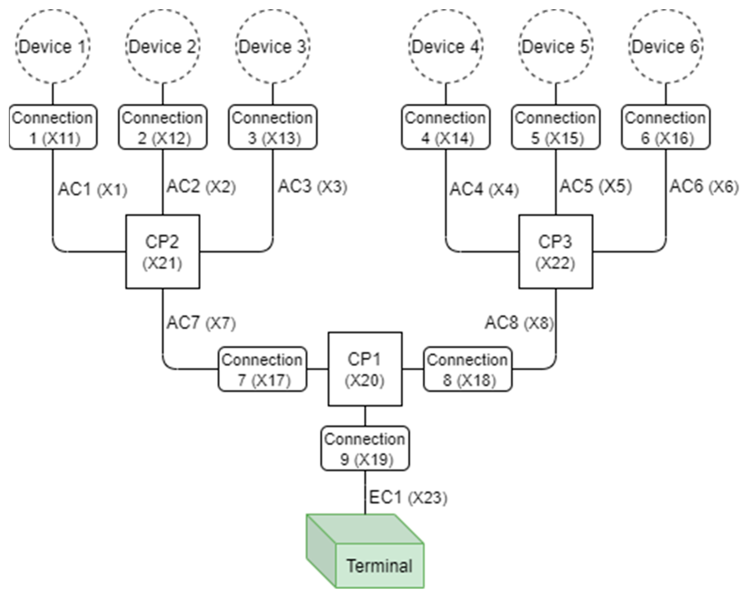
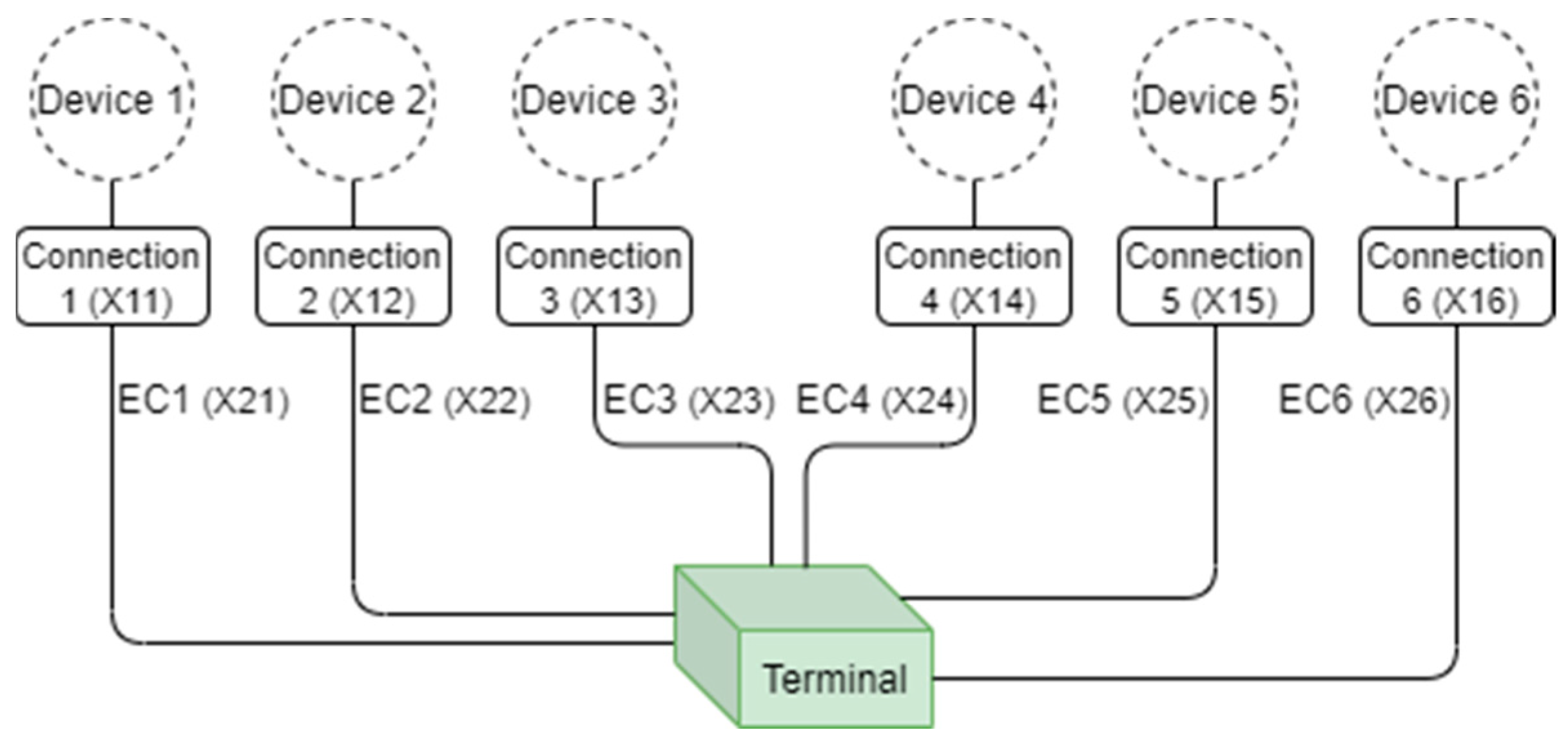
- “AC” represents array cable;
- “Connection” represents either: a connector in the case of a fixed device or an umbilical and its connectors for floating devices;
- “CP” represents the collection point. There are six devices in these network topologies for the demonstration purpose;
- “EC” represents the export cable.
3. Bayesian Network Formulation
- Bayesian network structure for the system: Calculate the current availability of the system given the current state of the basic components;
- Dynamic Bayesian network for calculation of time-dependent availability;
- Implementing repairs through decision rules.
3.1. Bayesian Network Structure for the System
3.2. Dynamic Bayesian Network Models
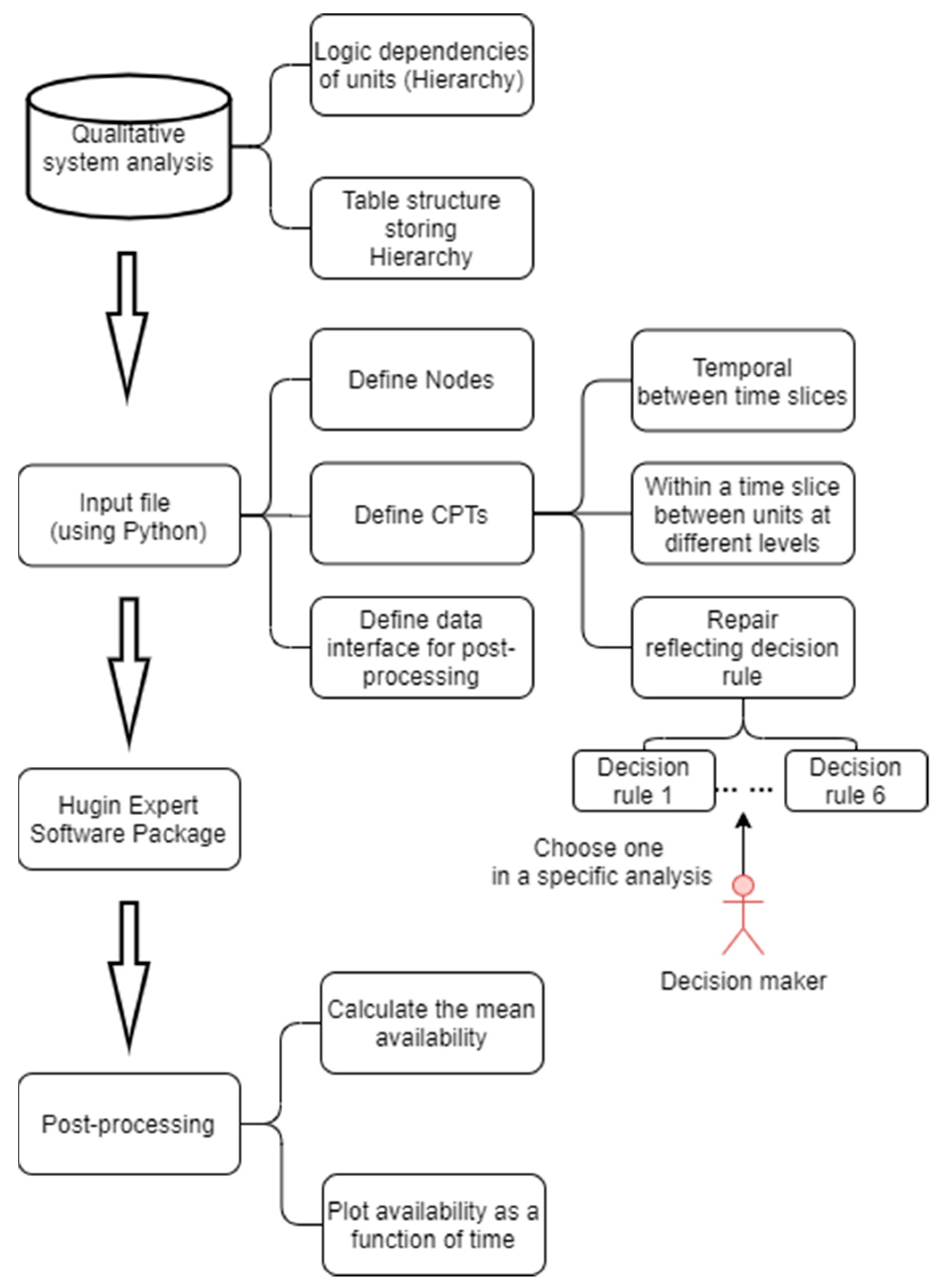
3.2.1. Conditional Probability Tables
3.2.2. Decision Rules
4. Case Study
4.1. Network Topologies
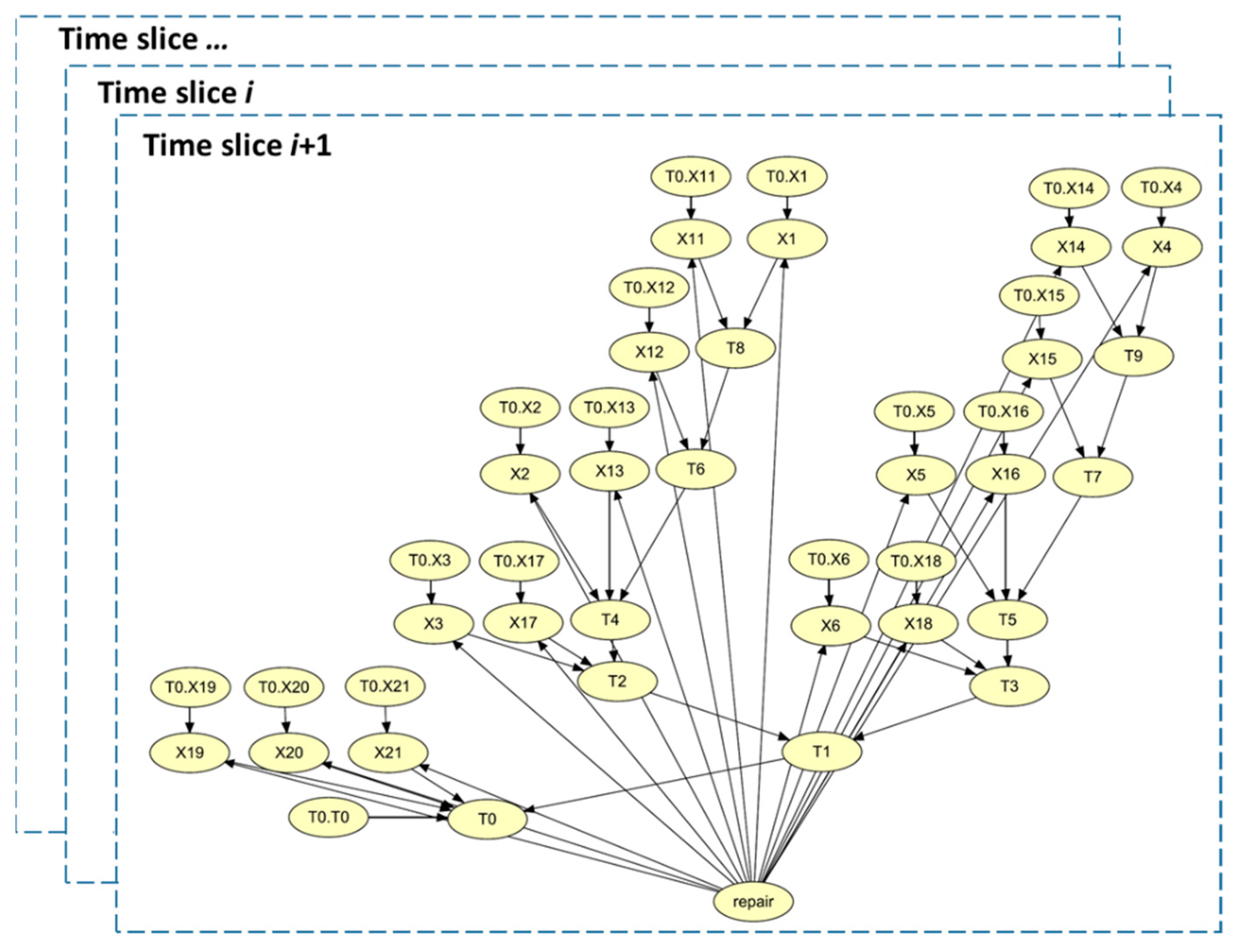
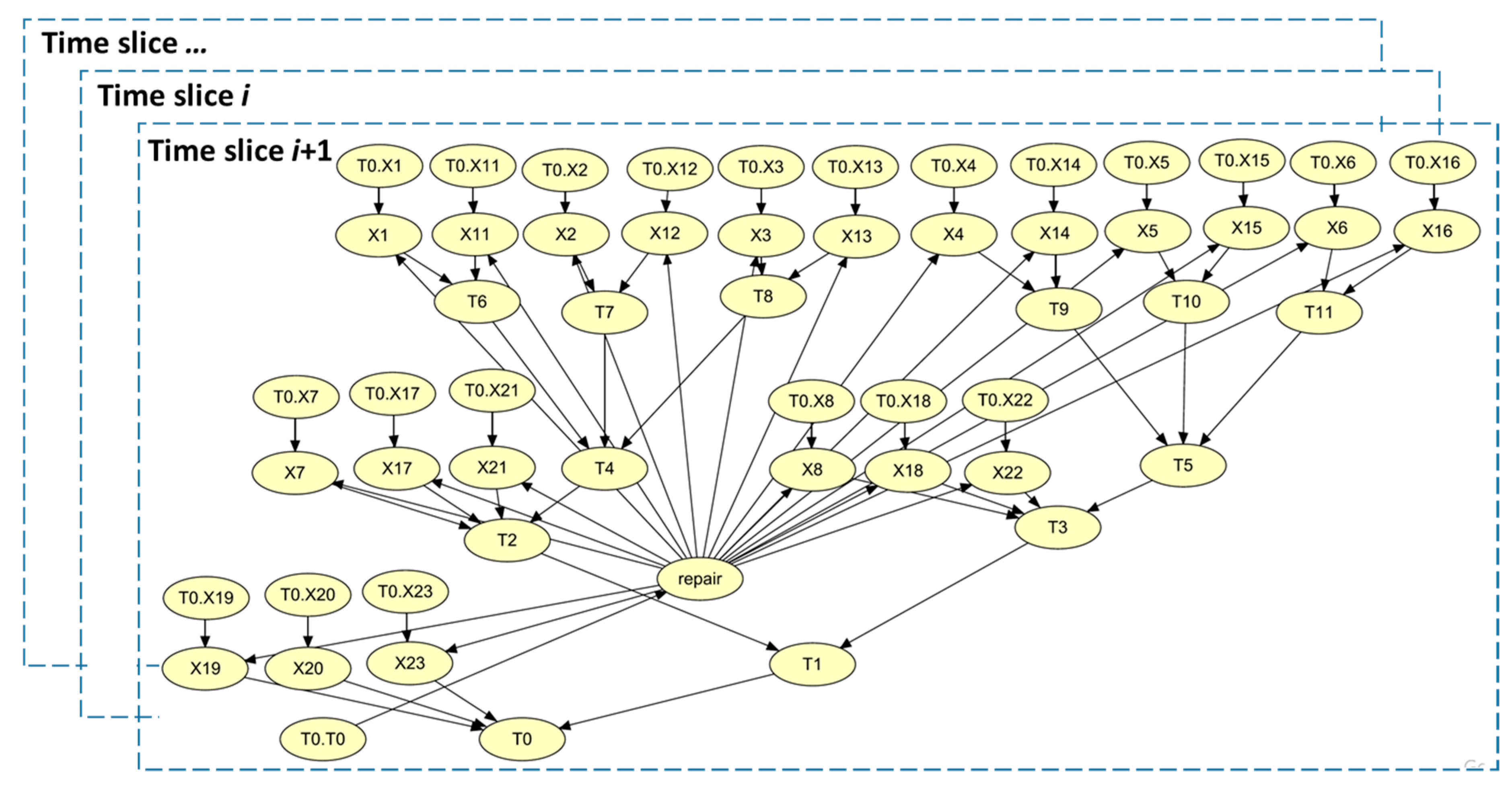
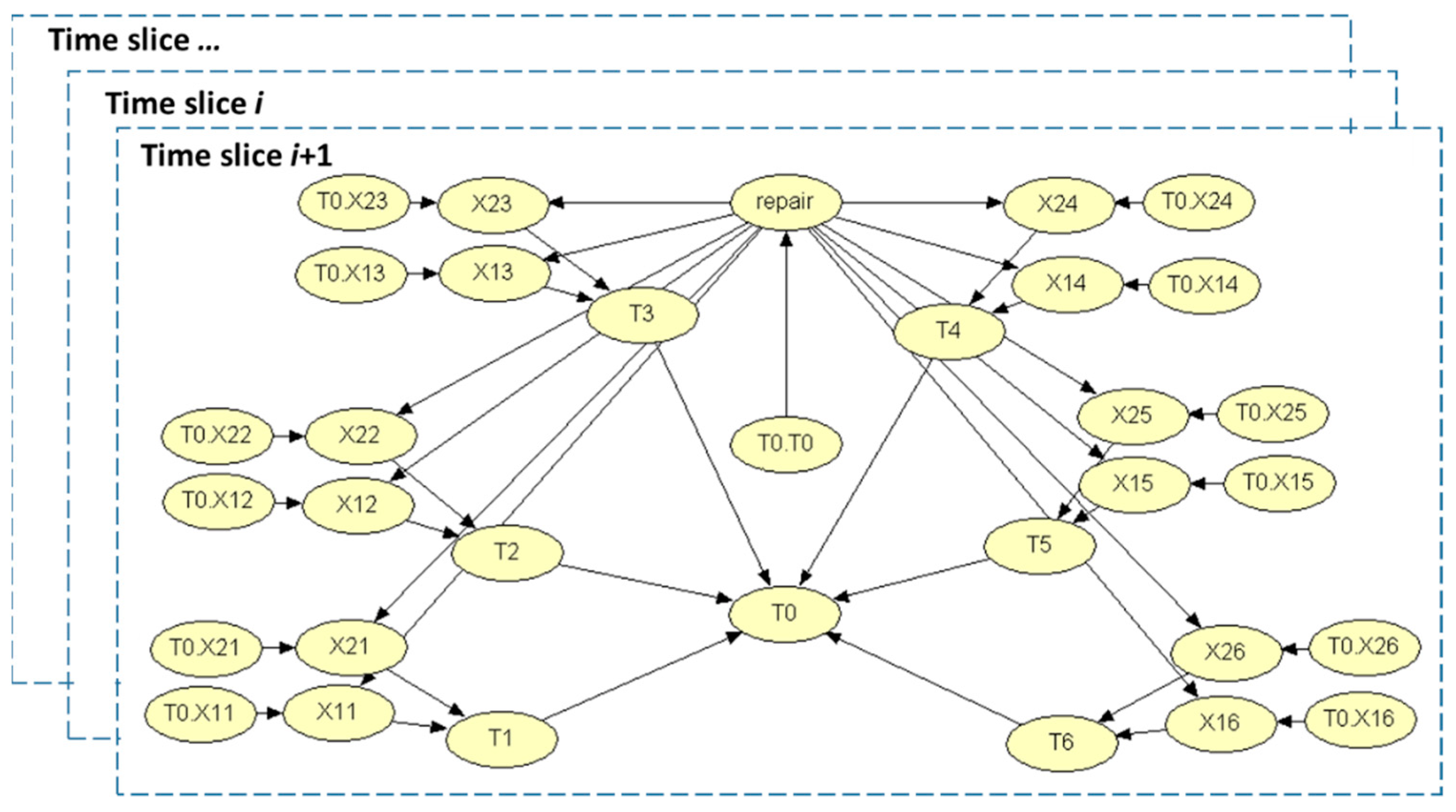
4.2. Logic Dependencies of the Topologies
- the system structure and the interrelationship between units at different level can be clearly represented without a long description.
- such a data structure is self-explanatory and can be easily implemented in computer code.
4.3. Bayesian Network Models
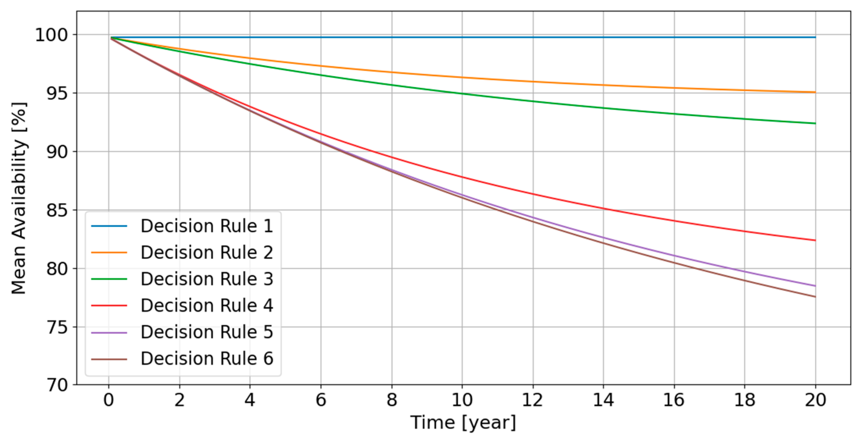
4.4. Calculation of Time-Dependent Availability
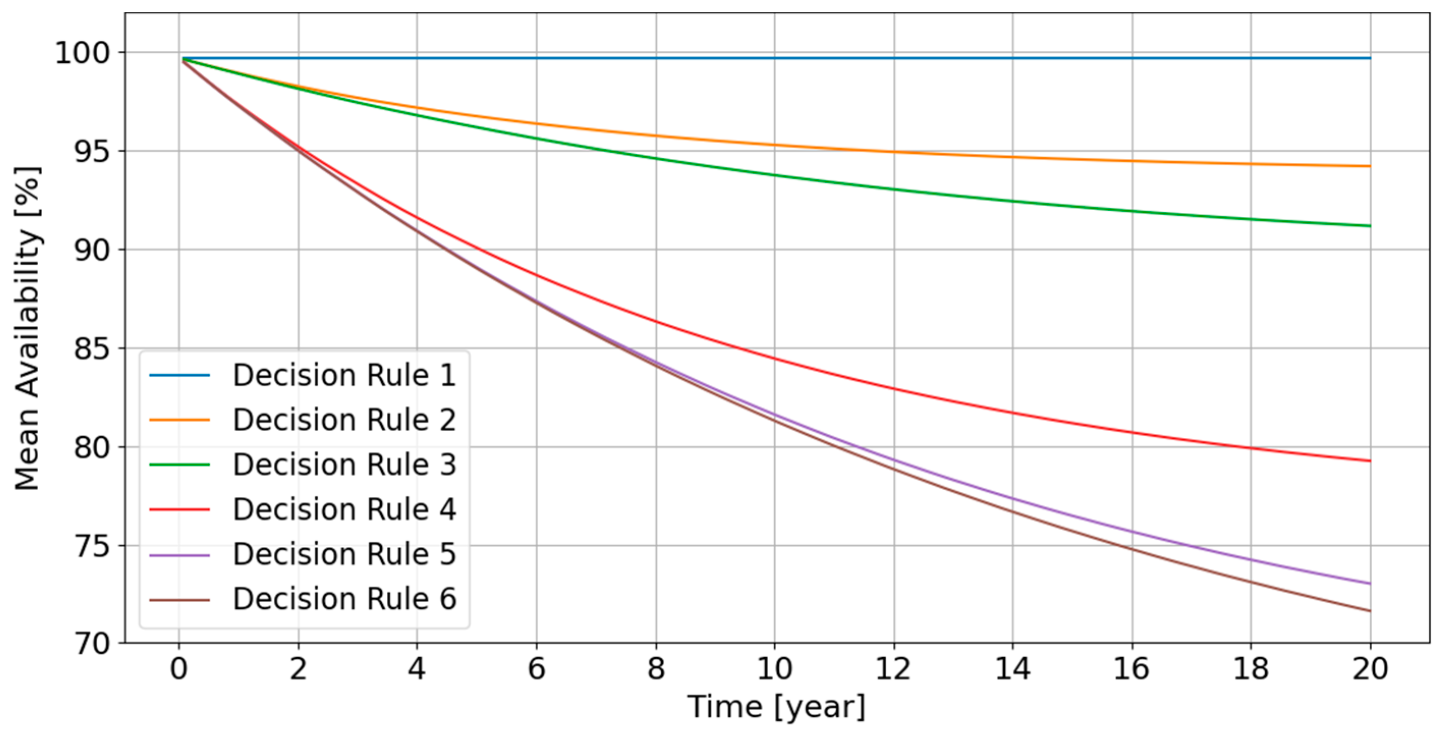
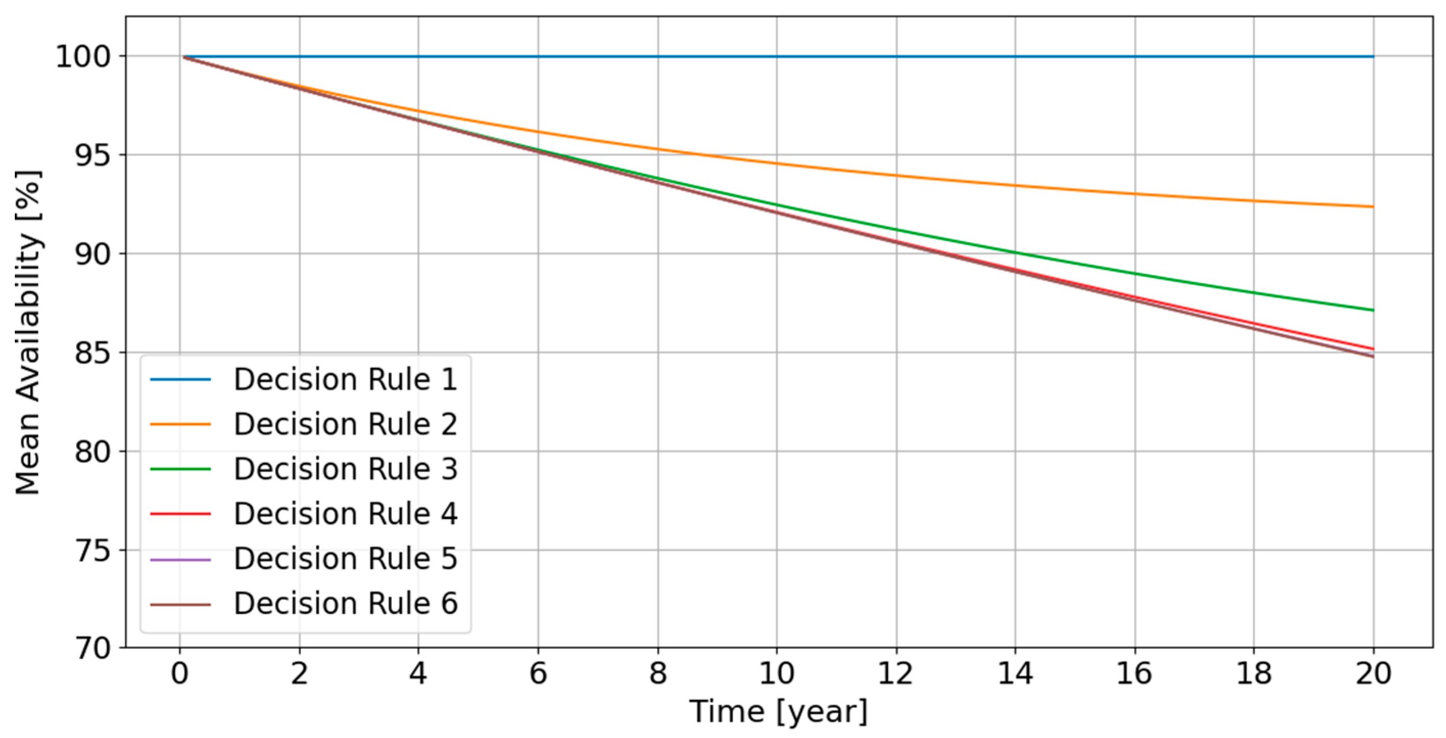
- The availability remains close to 100% (greater than 99%) if Decision rule 1 is chosen; this agrees with the engineering prediction, because Decision rule 1 indicates that repair must be done immediately if any basic component fails; the energy delivery network is almost always in a fully rated state and the system availability should remain close to 100%.
- For the decision rules other than Decision rule 1, the mean availability decreases with decreasing rate, thus stabilizing over long time. For Decision rules 2 and 3, there is no significant difference in the system availability between these topologies.
- For Decision rules 5 and 6, where more energy losses can be allowed, the availability is relatively low, because these decision rules exactly or almost correspond to a corrective maintenance strategy, respectively.
- For Decision rules 2 and 3, the decrease rate becomes slow after around Year 14. This indicates that these decision rules can ensure that the mean system availability stabilizes around a relatively high value in the long term.
- For the other decision rules, the availability decreases significantly over the design lifetime. A higher number of damaged basic components is allowed, which will definitely lower down the expected system availability.
- The Direct topology leads to higher mean availabilities for decision rules 4–6. This makes sense because the Direct topology resembles a parallel system, while Radial and Star topologies are more like a series of parallel systems; if more components are allowed to fail without repair, the parallel system should be able to work at a derated energy delivery level.
5. Conclusions
- the maintenance costs (OPEX costs) can be estimated by adding relevant nodes in the BN model;
- with the combination of CAPEX and OPEX costs, the optimal design solution to the energy delivery network can be finally determined.
Supplementary Materials
Author Contributions
Funding
Institutional Review Board Statement
Informed Consent Statement
Data Availability Statement
Acknowledgments
Conflicts of Interest
References
- Melikoglu, M. Current Status and Future of Ocean Energy Sources: A global review. Ocean Eng. 2018, 148, 563–573. [Google Scholar] [CrossRef]
- Alamiana, R.; Shafaghat, R.; Shadloo, M.S.; Bayani, R.; Amouei, A.H. An Empirical Evaluation of The Sea Depth Effects for Various Wave characteristics on The Performance of a Point Absorber Wave Energy Converter. Ocean Eng. 2017, 137, 13–21. [Google Scholar] [CrossRef]
- Mustapa, M.; Yaakob, O.; Ahmed, Y.M.; Rheem, C.-K.; Koh, K.; Adnan, F.A. Wave Energy Device and Breakwater Integration: A Review. Renew. Sustain. Energy Rev. 2017, 77, 43–58. [Google Scholar] [CrossRef]
- Falcao, A.D.d.O. Wave Energy Utilization: A Review of The Technologies. Renew. Sustain. Energy Rev. 2010, 14, 899–918. [Google Scholar] [CrossRef]
- Aderino, T.; Li, H. Ocean Wave Energy Converters: Status and Challenges. Energies 2018, 11, 1–26. [Google Scholar]
- IEC. IEC TS 62600-2 ED2 Marine Energy—Wave, Tidal and Other Water Current Converters—Part 2: Design Requirements for Marine Energy Systems; IEC: Geneva, Switzerland, 2018. [Google Scholar]
- Rinaldi, G.; Thies, P.R.; Walker, R.; Johanning, L. A Decision Support Model to Optimise the Operation and Maintenance Strategies of An Offshore Renewable Energy Farm. Ocean Eng. 2017, 145, 250–262. [Google Scholar] [CrossRef]
- Rinaldi, G.; Portillo, J.C.C.; Khalid, F.; Henriques, J.C.C.; Thies, P.R.; Gato, L.M.C.; Johanning, L. Multivariate Analysis of the Reliability, Availability, and Maintainability Characterizations of a Spar-buoy Wave Energy Converter Farm. J. Ocean Eng. Mar. Energy 2018, 4, 199–215. [Google Scholar] [CrossRef] [Green Version]
- Mason, A.; Driver, R.; Hay, S.; Hodges, R. Marine Energy Electrical Report 3: Optimum Electrical Array Architectures PN000083-LRT-008; CATAPULT Offshore Renewable Energy: Glasgow, UK, 2015. [Google Scholar]
- Noble, D.R.; Nambiar, A. DTOceanPlus—Advanced Design Tools for Ocean Energy Systems Innovation, Development and Deployment Deliverable D5.5—Alpha Version; The University of Edinburgh: Edinburgh, UK, 2020. [Google Scholar]
- Sharkey, F. Offshore Electrical Networks and Grid Integration of Wave Energy Converter Arrays—Techno-Economic Optimisation of Array Electrical Networks, Power Quality Assessment and Irisk Market Perspectives; Technological University Dublin: Dublin, Ireland, 2015. [Google Scholar]
- Yang, Y.; Sørensen, J.D. Probabilistic Availability Analysis for Marine Energy Transfer Subsystem Using Bayesian Network. Energies 2020, 13, 5108. [Google Scholar] [CrossRef]
- Department of Denfense. Military Handbook—Reliability Prediction of Electronic Equipment MIL-HDBK-217F; Department of Denfense: Washington, DC, USA, 1991. [Google Scholar]
- Walnock, J.; McMillan, D.; Pilgrim, J.; Shenton, S. Failure Rates of Offshore Wind Transmission Systems. Energies 2019, 12, 1–12. [Google Scholar]
- Hugin Expert A/S. Hugin API Reference Manual; Hugin Expert A/S: Aalborg, Denmark, 2018. [Google Scholar]

| Unit | Type | Child Nodes | Parent Nodes | Relation | States |
|---|---|---|---|---|---|
| T0 | System | N.A. | [T1, X3] | ‘OR’ | [0, 1, 2] |
| T1 | Sub-assembly | T0 | [X1, X2] | ‘AND’ | [0, 1, 2] |
| X1 | Basic Component | T1 | N.A. | N.A. | [0, 1] |
| X2 | Basic Component | T1 | N.A. | N.A. | [0, 1] |
| X3 | Basic Component | T0 | N.A. | N.A. | [0, 1] |
| Item | Labels in Sketch | Value [1/Hour] |
|---|---|---|
| Array cable | AC | 3.31 × 10⁻⁷ |
| Export cable | EC | 3.31 × 10⁻⁷ |
| Connection | Connector | 6.24 × 10⁻⁷ |
| CP | CP | 9.83 × 10⁻⁷ |
| Unit | Type | Child Nodes | Parent Nodes | Relation |
|---|---|---|---|---|
| T0 | System | N.A. | [X19, X20, X21, T1] | OR |
| T1 | 1st-level sub-assembly | T0 | [T2, T3] | AND |
| T2 | 2nd-level sub-assembly | T1 | [X17, X3, T4] | OR |
| T3 | 2nd-level sub-assembly | T1 | [X18, X6, T5] | OR |
| T4 | 3rd-level sub-assembly | T2 | [X13, X2, T6] | 2/3 |
| T5 | 3rd-level sub-assembly | T3 | [X16, X5, T7] | 2/3 |
| T6 | 4th-level sub-assembly | T4 | [X12, T8] | OR |
| T7 | 4th-level sub-assembly | T5 | [X15, T9] | OR |
| T8 | 5th-level sub-assembly | T6 | [X11, X1] | OR |
| T9 | 5th-level sub-assembly | T6 | [X14, X4] | OR |
| X11 | Basic Component (Device) | T8 | N.A. | N.A. |
| X12 | Basic Component (Device) | T6 | N.A. | N.A. |
| X13 | Basic Component (Device) | T4 | N.A. | N.A. |
| X14 | Basic Component (Device) | T9 | N.A. | N.A. |
| X15 | Basic Component (Device) | T7 | N.A. | N.A. |
| X16 | Basic Component (Device) | T5 | N.A. | N.A. |
| X17 | Basic Component | T2 | N.A. | N.A. |
| X18 | Basic Component | T3 | N.A. | N.A. |
| X19 | Basic Component | T0 | N.A. | N.A. |
| X1 | Basic Component | T8 | N.A. | N.A. |
| X2 | Basic Component | T4 | N.A. | N.A. |
| X3 | Basic Component | T2 | N.A. | N.A. |
| X4 | Basic Component | T9 | N.A. | N.A. |
| X5 | Basic Component | T5 | N.A. | N.A. |
| X6 | Basic Component | T2 | N.A. | N.A. |
| X20 | Basic Component | T0 | N.A. | N.A. |
| X21 | Basic Component | T0 | N.A. | N.A. |
| Unit | Type | Child Nodes | Parent Nodes | Relation |
|---|---|---|---|---|
| T0 | System | N.A. | [X19, X20, X23, T1] | OR |
| T1 | 1st-level sub-assembly | T0 | [T2, T3] | AND |
| T2 | 2nd-level sub-assembly | T1 | [X7, X17, X21, T4] | OR |
| T3 | 2nd-level sub-assembly | T1 | [X8, X18, X22, T5] | OR |
| T4 | 2nd-level sub-assembly | T2 | [T6, T7, T8] | AND |
| T5 | 2nd-level sub-assembly | T3 | [T9, T10, T11] | AND |
| T6 | 3rd-level sub-assembly | T4 | [X1, X11] | OR |
| T7 | 3rd-level sub-assembly | T4 | [X2, X12] | OR |
| T8 | 3rd-level sub-assembly | T4 | [X3, X13] | OR |
| T9 | 3rd-level sub-assembly | T5 | [X4, X14] | OR |
| T10 | 3rd-level sub-assembly | T5 | [X5, X15] | OR |
| T11 | 3rd-level sub-assembly | T5 | [X6, X16] | OR |
| X1 | Basic Component | T6 | N.A. | N.A. |
| X2 | Basic Component | T7 | N.A. | N.A. |
| X3 | Basic Component | T8 | N.A. | N.A. |
| X4 | Basic Component | T9 | N.A. | N.A. |
| X5 | Basic Component | T10 | N.A. | N.A. |
| X6 | Basic Component | T11 | N.A. | N.A. |
| X7 | Basic Component | T2 | N.A. | N.A. |
| X8 | Basic Component | T3 | N.A. | N.A. |
| X11 | Basic Component (Device) | T6 | N.A. | N.A. |
| X12 | Basic Component (Device) | T7 | N.A. | N.A. |
| X13 | Basic Component (Device) | T8 | N.A. | N.A. |
| X14 | Basic Component (Device) | T9 | N.A. | N.A. |
| X15 | Basic Component (Device) | T10 | N.A. | N.A. |
| X16 | Basic Component (Device) | T11 | N.A. | N.A. |
| X17 | Basic Component | T2 | N.A. | N.A. |
| X18 | Basic Component | T3 | N.A. | N.A. |
| X19 | Basic Component | T0 | N.A. | N.A. |
| X20 | Basic Component | T0 | N.A. | N.A. |
| X21 | Basic Component | T2 | N.A. | N.A. |
| X22 | Basic Component | T3 | N.A. | N.A. |
| X23 | Basic Component | T0 | N.A. | N.A. |
| Unit | Type | Child Nodes | Parent Nodes | Relation |
|---|---|---|---|---|
| T0 | System | N.A. | [T1, T2, T3, T4, T5, T6] | AND |
| T1 | 1st-level sub-assembly | T0 | [X11, X21] | OR |
| T2 | 1st-level sub-assembly | T0 | [X12, X22] | OR |
| T3 | 1st-level sub-assembly | T0 | [X13, X23] | OR |
| T4 | 1st-level sub-assembly | T0 | [X14, X24] | OR |
| T5 | 1st-level sub-assembly | T0 | [X15, X25] | OR |
| T6 | 1st-level sub-assembly | T0 | [X16, X26] | OR |
| X11 | Basic Component (Device) | T1 | N.A. | N.A. |
| X12 | Basic Component (Device) | T2 | N.A. | N.A. |
| X13 | Basic Component (Device) | T3 | N.A. | N.A. |
| X14 | Basic Component (Device) | T4 | N.A. | N.A. |
| X15 | Basic Component (Device) | T5 | N.A. | N.A. |
| X16 | Basic Component (Device) | T6 | N.A. | N.A. |
| X21 | Basic Component | T1 | N.A. | N.A. |
| X22 | Basic Component | T2 | N.A. | N.A. |
| X23 | Basic Component | T3 | N.A. | N.A. |
| X24 | Basic Component | T4 | N.A. | N.A. |
| X25 | Basic Component | T5 | N.A. | N.A. |
| X26 | Basic Component | T6 | N.A. | N.A. |
Publisher’s Note: MDPI stays neutral with regard to jurisdictional claims in published maps and institutional affiliations. |
© 2021 by the authors. Licensee MDPI, Basel, Switzerland. This article is an open access article distributed under the terms and conditions of the Creative Commons Attribution (CC BY) license (https://creativecommons.org/licenses/by/4.0/).
Share and Cite
Yang, Y.; Nielsen, J.S. Availability-Based Selection of Electricity Delivery Network in Marine Conversion Systems Using Bayesian Network. Energies 2021, 14, 3574. https://doi.org/10.3390/en14123574
Yang Y, Nielsen JS. Availability-Based Selection of Electricity Delivery Network in Marine Conversion Systems Using Bayesian Network. Energies. 2021; 14(12):3574. https://doi.org/10.3390/en14123574
Chicago/Turabian StyleYang, Yi, and Jannie Sønderkær Nielsen. 2021. "Availability-Based Selection of Electricity Delivery Network in Marine Conversion Systems Using Bayesian Network" Energies 14, no. 12: 3574. https://doi.org/10.3390/en14123574
APA StyleYang, Y., & Nielsen, J. S. (2021). Availability-Based Selection of Electricity Delivery Network in Marine Conversion Systems Using Bayesian Network. Energies, 14(12), 3574. https://doi.org/10.3390/en14123574


