Article

Potential of the Middle Cambrian Aquifer for Carbon Dioxide Storage in the Baltic States

Faculty of Geography and Earth Sciences, University of Latvia, Jelgavas Str. 1, LV-1004 Riga, Latvia
*
Author to whom correspondence should be addressed.
Energies 2021, 14(12), 3681; https://doi.org/10.3390/en14123681
Submission received: 25 May 2021 / Revised: 15 June 2021 / Accepted: 18 June 2021 / Published: 21 June 2021
(This article belongs to the Special Issue CO2 Capture, Transportation, Utilization, and Storage)

Abstract

:
The importance of CO2 removal from the atmosphere has long been an essential topic due to climate change. In this paper, the authors aim to demonstrate the suitability of the underground reservoirs for CO2 storage based on their geological characteristics. The research addressed the potential of geological formations for fossil CO2 storage in the Baltic States to support the goal of achieving carbon neutrality in the region. The geological, technical, and economic feasibility for CO2 storage has been assessed in terms of carbon sequestration in geological structures and the legal framework for safe geological storage of fossil CO2. Results indicate that prospective structural traps in the Baltic States, with reasonable capacity for CO2 storage, occur only in Southwestern Latvia (onshore) and in the Baltic Sea (offshore), whilst other regions in the Baltics either do not meet basic geological requirements, or have no economically feasible capacity for CO2 storage. Based on the examination of geological characteristics, the most fitting is the middle Cambrian reservoir in the Baltic sedimentary basin, and one of the most prospective structural traps is the geological structure of Dobele, with an estimated storage capacity of 150 Mt CO2. This study revealed that the storage capacity of the middle Cambrian reservoir (up to 1000 Mt CO2) within the borders of Southwestern Latvia is sufficient for carbon capture and safe storage for the whole Baltic region, and that geological structures in Latvia have the capacity to store all fossil CO2 emissions produced by stationary sources in the Baltic States for several decades.

1. Introduction

The estimated concentration of CO2 in the Earth’s atmosphere has increased from approximately 277 ppm in 1750 to 419 ppm in 2021, indicating that the Industrial Era has significantly added to climate change. However, increased and decreased concentrations of CO2 in the atmosphere traced throughout Earth’s history can also be due to natural causes, like in the interglacial (increase) and glacial (decrease) periods. The highest natural CO2 concentration of 300 ppm occurred 350,000 years ago [1]. At the same time, a rapid increase in CO2 concentration nowadays is commonly related to modern human activities, such as fossil fuel burning and deforestation, and this far exceeds any natural increase in concentration. This considerable increase in the atmospheric CO2 and in the concentrations of other greenhouse gases (GHGs) has resulted in changes in the carbon biogeochemical cycle, particularly in changes of carbon cycling among reservoirs in the atmosphere, hydrosphere, and terrestrial biosphere. Moreover, this increase has also substantially changed the Earth’s climate system [2]. The ongoing climate change due to changes in the atmospheric composition can be considered as one of the main threats to civilisation. Therefore, reduction of GHG emissions is crucial for survival.
Climate change mitigation covers efforts and actions to reduce and prevent GHG emissions. To mitigate global climate change and to keep global warming below 2 °C, it is crucial to reduce GHG emissions, especially fossil CO2 emissions. To achieve this long-term temperature goal and GHG emission reduction, 196 countries at the 21st Conference of the Parties in Paris on 12 December 2015 adopted the Paris Agreement, which entered into force on 4 November 2016 [3]. In addition, in 2018 the intergovernmental panel on climate change (IPCC) made a special report, where a revised target of a temperature rise below 1.5 °C was addressed, which then became the basis for further development of the policy. In comparison to a 2 °C limit, the activities required to limit warming to 1.5 °C are more pronounced and rapid over the next few decades, but overall, they are qualitatively similar [4]. Strategies that were proposed to achieve the reduction of CO2 emissions and limit warming to 1.5 °C included the expansion of renewable energy usage, reduction of energy consumption patterns, and other approaches [5]. However, all known strategies have limitations, and keeping this in mind, separation of CO2 from flue gas flow by capturing it before emitting into the atmosphere—that is, the carbon capture—can be considered as one of the most promising approaches. One prospective solution to mitigate climate change is injection of CO2 in deep geological formations for stable and permanent storage, thus removing fossil CO2 from active circulation within the carbon cycle [6,7].
The three main types of carbon capture and storage (CCS) technologies are pre-combustion, post-combustion, and oxyfuel [8,9,10]. The pre-combustion technology uses fossil fuel gasification to produce a synthetic gas made of CO and H2. The CO in reaction with water produces CO2, which is then captured and delivered to a storage site. Additionally, formed H2 can be used as a fuel to produce electricity, or used in hydrogen fuel cells. Admittedly, the pre-combustion method requires modern powerplant technology and cannot be retrofitted to older pulverised powerplants that dominate worldwide [9]. Meanwhile, it would be technologically possible to use the pre-combustion method in natural gas powerplants, where CO2 can be produced and captured in a CH4 reaction with steam. However, the economic advantage of the pre-combustion method over other CCS technologies has yet to be proven [9]. The most widely used CCS technology with proven efficiency and economic advantage is the post-combustion method [8]. This method is focused on CO2 capture using advanced solvent, sorbent, and membrane systems. Solvent systems are based on CO2 absorption from flue gas into a liquid carrier. The CO2 is separated from the flue gas by transferring gas through an absorber column packed with liquid solvents (water-lean, phase-change, high-performance functionalised solvents, etc.). When solvents in the absorber column become saturated, a stream of 120 °C is passed through to release the trapped CO2, which can then be transported to the underground storage site [8]. Sorbent systems are based on CO2 adsorption using a solid sorbent. Unfortunately, sorbent-based technologies are generally less developed and less effective than solvent-based systems [8]. Membrane systems are based on permeable materials that allow for the selective transport and separation of CO2 from flue gas [8]. The post-combustion method also includes a technique where CO2 is absorbed by seawater. However, the “seawater” method is the least effective and reliable among other post-combustion options [8]. The oxyfuel method is based on fossil fuel combustion in a pure oxygen environment. In this setting, the waste gas is composed of CO2 and water vapour. The produced vapour can be condensed out of the system, while the CO2 can be piped to a storage site [10]. The oxyfuel method is by far the most challenging and economically ineffective approach for carbon capture, as it can use up to 15% of the power produced at the station for separation of a large volume of air into liquid O2, gaseous N2, Ar, and other trace gases [10].
Among options for atmospheric CO2 capture, there are also passive methods that have attracted scientific attention. One of the prominent methods is passive CO2 removal in urban soils [11,12,13,14]. Cities are interested in redeveloping degraded urban soils, such as brownfields, to promote environmental sustainability and improve environmental stewardship. Construction and demolition waste containing concrete, dust, and lime has large concentrations of Ca2+, which can efficiently bind CO2 and lock it in the degraded soil in the form of CaCO3. As a matter of fact, the full potential and magnitude of this approach has not yet been fully acknowledged, as existing studies address a limited range of set conditions. Therefore, further in-depth research of this option is required to identify its benefits and justify its implementation [12]. The use of specific vegetation (photosynthetic removal of CO2) on these degraded soils can further enhance the efficiency of carbon capture. In fact, the potential of urban greenspace to reduce atmospheric CO2 concentration has been of scientific interest in relation to climate change mitigation for several decades [11,14].
Porous geological structures with an adequate storage capacity and dense and compact surrounding sediments, which can work as natural insulation to prevent CO2 leakage, have the highest potential as CO2 traps. Considerable attention in many commercial-scale projects for CO2 storage worldwide has been paid to porous rock formations, which can also be used as oil and gas reservoirs. The economic benefit of these structures can offset the cost of CCS several times, keeping in mind that the price of carbon emission is gradually but rapidly rising [15,16]. Depleted hydrocarbon deposits, deep saline aquifers, basalt formations, organic-rich shales, and unmineable coal seams are among the most fitting structures for CO2 storage [17,18,19,20,21,22,23,24]. For example, basalt formations in the sea offer a unique environment for carbon sequestration. The injected CO2 mixes with seawater, which then reacts with silicates in basalt, and consequently, Ca2+ and Mg2+ ions are released and form stable carbonate minerals [22]. Carbon storage in unmineable coal seams can be made possible with concomitant enhancement of coalbed methane production [23]. However, a reliable technology for CO2 storage in coal beds has not yet been developed, and better understanding of this option is needed. Meanwhile, organic-rich shale formations have the ability to trap CO2 through adherence to the surface, subsequently releasing methane, which is the cleanest of the fossil fuels [21,25]. Depleted oil and gas reservoirs are among the most promising structures for CO2 storage worldwide. However, not many hydrocarbon reservoirs are depleted or are near depletion, and so this approach cannot be used as an immediate option worldwide [18]. Two large CO2 storage projects are currently taking place in Algeria (In Salah gas field) and the North Sea (Sleipner field), where large amounts of CO2 are successfully being injected in saline aquifers annually [18]. The CO2 is injected underground not only for storage, but also because of the added economic benefit—to recover oil, which is practiced in West Texas and Canada [18]. Interestingly, there are major differences between states of CO2 storage depending on media due to distinction and variations among geological conditions, such as permeability, density, pore size, temperature, and other parameters. There are also considerable differences in storage and maintenance costs among different types of geological structures. At the same time, deep saline aquifers, in comparison to other geological formations, have the greatest CO2 storage capacity potential, even if it might not be the cheapest option [26].
The state of stored CO2 depends on the geological conditions of a selected reservoir. In deep saline aquifers, CO2 can be injected as a supercritical fluid. Moreover, properties of deep saline aquifers promote CO2 mineralisation by turning it into carbonate minerals, while in other media, such as depleted gas reservoirs, this might not be the case [26,27]. Mineralization is a natural mechanism to sequester CO2; however, it is a slow process. Therefore, geological, physical, chemical, and techno-economic factors are crucial for the selection of a CO2 storage site [18,20], whereas the identification of geological structures for safe storage and the development of cost-effective CCS technologies to ensure safe and publicly acceptable CO2 storage are crucial for climate change mitigation [28,29].
CO2 storage in saline aquifers depends on the pressure and temperature of the media, with the highest efficiency being at more than 73 bar and 31 °C. In the conditions with a proper pressure and temperature regime, the injected carbon will fill the available pore spaces, and the density of the stored CO2 will be about 50 to 80% of the density of water, that is, 0.5 to 0.8 g/m3, respectively. After the injection, CO2 will be locked in the aquifer by physical and geochemical trapping mechanisms, such as structural and residual trapping, solubility, and mineral trapping [30]. The main requirement here is a depth of the reservoir sufficient to ensure that the CO2 reaches its supercritical dense phase, but not so deep that the permeability and porosity of the media become too low [31].
The mitigation of climate change and reduction of GHG emissions are topical matters for the Baltic Sea region, including the Baltic States (Estonia, Latvia, and Lithuania), where the emissions from industries and factories are of concern to climate-neutral Europe. Emissions of CO2 vary among the three Baltic States and directly depend on their socio-economic conditions, such as the size of the economy and the share of renewable energy in the gross energy consumption.
According to the Eurostat database on greenhouse gas emissions, the estimated emissions of CO2 in 2018, including emissions from households were 18.38 Mt CO2 in Estonia, 19.71 Mt CO2 in Lithuania, and 9.69 Mt CO2 in Latvia [32]. These data indicate that the CO2 emissions from economic activity in Latvia in recent years have been almost two times lower than in Estonia and Lithuania. The largest amounts of fossil CO2 emissions in Estonia come from the energy industry, which mostly operates by oil shale combustion, while in Lithuania and Latvia, emissions on energy generation are significantly lower due to domination of hydropower plants and intensive use of biomass and wind energy, which are considered carbon-neutral energy sources. The Baltic States, as part of the European Union (EU), aim to further reduce GHG emissions and achieve the goals of the ambitious European Green Deal, and they fully acknowledge the utmost importance of the implementation of CCS technologies [33].
The aim of this paper is to re-evaluate the potential for fossil CO2 storage in deep geological structures of the middle Cambrian aquifer in the Baltic States. In addition, authors intend to define major emission sources in the Baltic States and reflect on whether it is possible to reduce them using CCS technologies locally. The re-evaluation is crucial, as legal documents are still based on data from the last century, whereas the research into the region since then has expanded and the technological capabilities have improved significantly, while the price ratio between carbon storage and the carbon emission price has shifted toward a storage-favourable direction. The middle Cambrian reservoir within the Baltic sedimentary basin in Latvia is considered as prevailing compared to other structures in the Baltic States due to availability of the most economically justifiable geological traps for safe CO2 storage, with the potential total storage capacity ranging between 600 and 1000 Mt CO2.

2. Materials and Methods

2.1. Regulatory Guiding Principles for CO2 Storage in Europe

Geological storage of CO2 in the EU is subject to Directive 2009/31/EC of the European Parliament, which has been introduced to ensure safe CO2 storage with minimal risks of leakage or damage to the environment [34]. Potential risks occurring due to mismanagement of operating a CO2 storage site include temporal and spatial migration of the CO2 plume (dispersing volume of CO2 in the geological formation) and pressure point, geochemical reactions that can change long-term porosity and permeability of the trap, wellbores and seals that can lose their integrity and cause CO2 leakage, and others. At the same time, all EU Member States keep the right to decide on potential storage sites on their land [35,36,37].

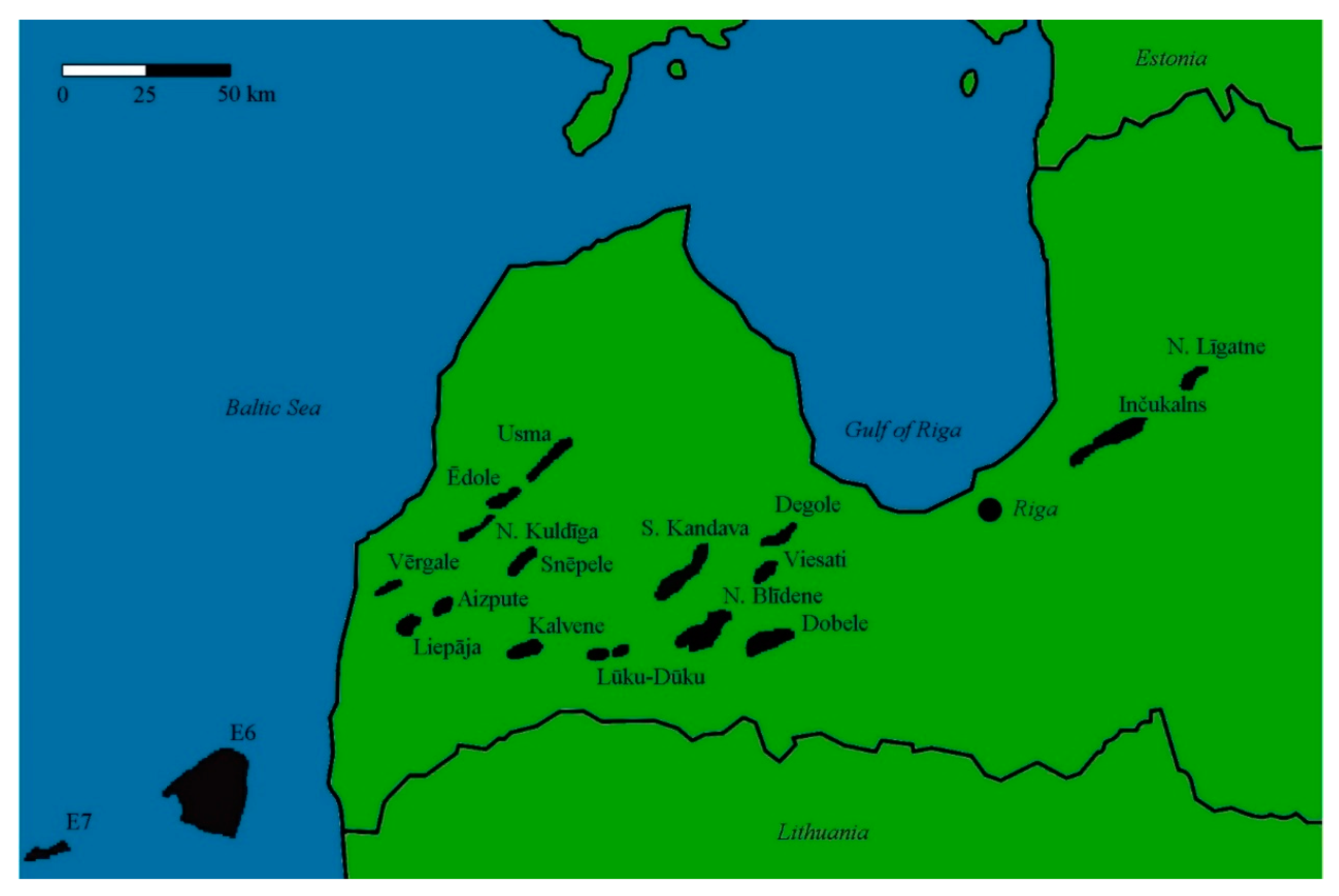
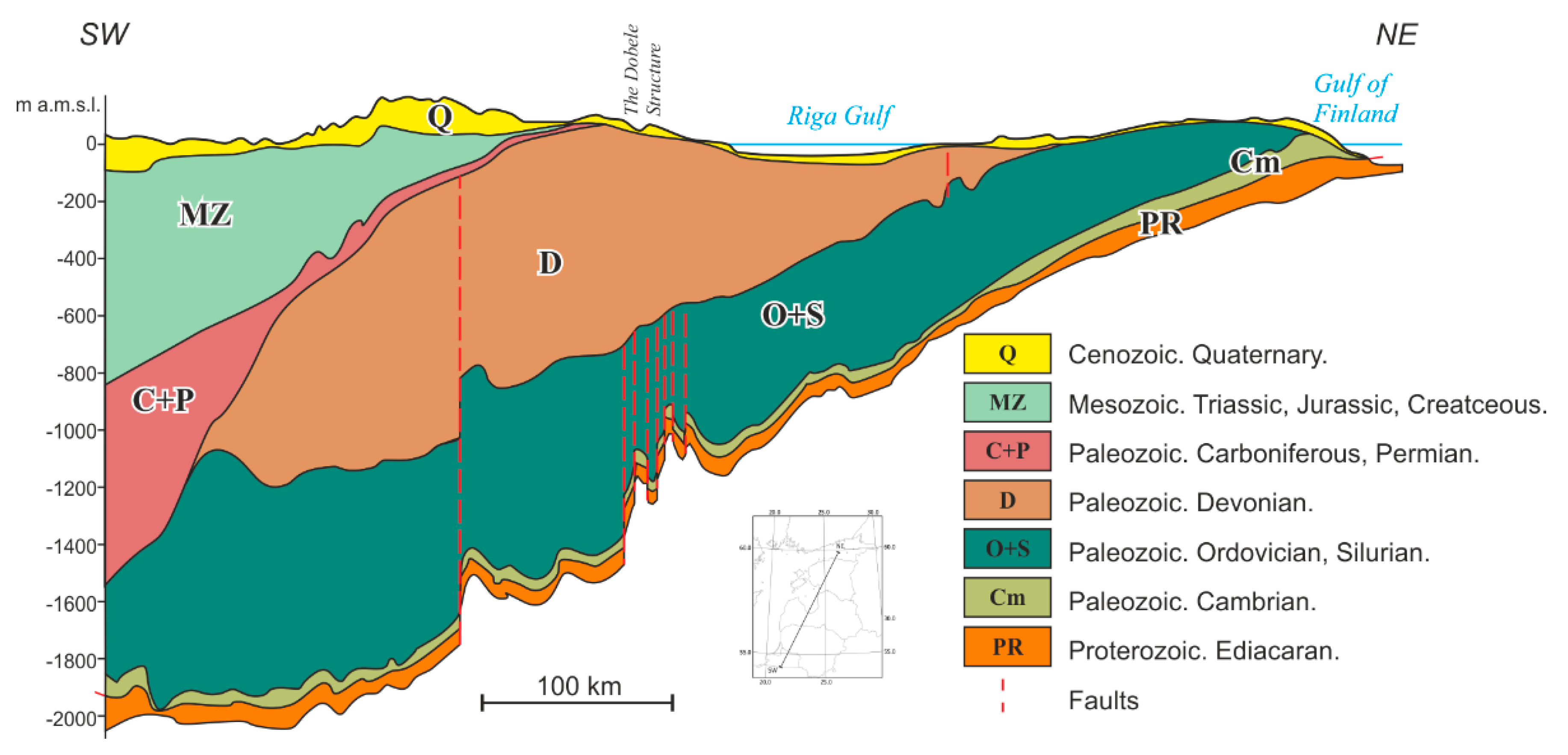
2.2. Location of the Study Subject: The Dobele Structure

This article is focused on the evaluation of the middle Cambrian reservoir within the Baltic sedimentary basin, especially the Dobele structure, which is considered as one of the most promising geological formations for safe CO2 geological storage in the Baltic States, based on the geological, geographical, and economic factors. The Dobele structure (56°36′20″ N, 22°58′30″ E) is in Dobele Municipality in Southwestern Latvia (Figure 1). The central part of the structure is situated approximately 12 km from Dobele town and 70 km from Riga, the capital of Latvia, and it is also relatively close to other major industrial centres in Latvia (Jelgava, Liepāja, and others) and Lithuania (Kaunas, Vilnius, Akmene, and others). The Dobele anticline structure belongs to the first group of prospective structures for CO2 storage and, alongside with the Kalvene, Lūku-Dūku, North Blīdene, and North Līgatne structures (Figure 1), is situated within the Liepāja-Saldus ridge and includes several near-fault brachy-anticline folds of the Caledonian structural complex [38,39,40].
The Dobele structure is sealed by Silurian and Ordovician clayey carbonate rocks. The surface of the middle Cambrian reservoir in the wells of the lifted part of the structure is revealed at a depth of around 950 m, with a 70 m average thickness of the structure and an occupied area of approximately 70 km2 [42,43,44,45,46].

2.3. Calculation of the Storage Capacity of the Structure

The area, shape, and volume of the Dobele structure were identified based on the geological, structural, and stratigraphic data on the region [47]. The assessment of CO2 storage capacity was based on the estimates in the Geo-Capacity database and Equation (1), designed for storage calculation in deep saline aquifers [48]:
SCCO2 = A × h × NTG × φ × ρCO2 × SEfac.
Parameters in the equation are as follows: SCCO2 is the CO2 storage capacity; A is the area of the aquifer; h is the average thickness of the aquifer; NTG is the best estimate of the net-to-gross ratio; φ is the best estimate of the average porosity; ρCO2 is the best estimate of the CO2 density; and SEfac is the storage efficiency factor for trap volume.
The thickness, porosity, and net-to-gross ratio were evaluated using data from the exploration wells drilled in the structure and from extrapolating information from the wells in the nearby structures and other data available at the Latvian Environment, Geology and Meteorology Centre (LEGMC) and the State Geological Fund [40,43,47]. The density of CO2 varies with depth as the function of pressure and temperature. The Dobele structure is throughout homogenous formation with high porosity; thus, the best estimates were used to calculate the storage capacity and the storage efficiency factor, which was therefore set to 40%, as recommended in the literature [16,41].

2.4. Additional Methods for Evaluation of a CO2 Storage Site

The composition and properties of a potential CO2 storage site are usually studied using not only seismological and electromagnetic geophysical research methods, but also analysis of sediments collected from wells that represent the buried basin in detail [49]. The bulk chemical composition of storage media may additionally be analysed with X-ray diffraction and X-ray fluorescence [50]. The studied parameters generally include petrophysical properties, such as gas permeability, wet and grain density, and effective porosity of the media, as these have a major impact on storage conditions [41].

2.5. Factors Determining CO2 Storage Efficiency

A storage site is expected to isolate and permanently store the injected CO2, therefore it is not only the porosity and permeability of the potential CO2 trap that are essential, but also the estimation of potential risks of leaking, the thermo- and hydrodynamics of the structure, and the proximity to the CO2 emission source [20,35,36,51]. Moreover, possibilities for use and reuse of once-captured CO2 and the potential of carbon sequestration must be assessed [35,36,51].

2.6. Evaluation of the Criteria and Requirements for a Prospective CO2 Trap

The main criteria used for identification of a prospective local CO2 trap are the local height, the size and depth of the structure, and the geological characteristics of the aquifer, such as porosity, permeability, salinity, and so forth. For evaluation of a potential reservoir, the analysis of stratigraphical and structural traps for more precise estimates, identification of suitable reservoir and sealing properties within the aquifer, and calculation of the storage potential of the individual trap are necessary. Moreover, geographical information system (GIS) databases need to be consulted for updated CO2 emission data, including technical information on the industry, capacity, technology, infrastructure, and other factors crucial for evaluation of the economic justifiability of possible CCS application. A prospective CO2 trap should meet certain requirements, among which the most important are the large volume of the reservoir, adequate depth and temperature, the presence of a reliable seal, and structural tightness [42,52]. Furthermore, characterisation of a potential CO2 storage site should be based on data collection, construction of a three-dimensional model of the CO2 trap, and assessment of the dynamics of the storage site and potential risks of leakage, pollution, and damage to the environment [20].

3. Results and Discussion

3.1. Fossil CO2 Emission Sources in the Baltic States

The total CO2 capture potential in the Baltic States using “End-of-Pipe” technologies is about 18.68 Mt CO2 per year. This figure includes 16.04 Mt CO2, which is mainly generated in the production of heat and electricity, and about 2.64 Mt CO2 is generated in the production of various mineral products, such as gypsum and cement. This figure can be concretised by a more detailed study of the CO2 capture potential depending on the size of the specific production plants and the technological processes used.
Fossil CO2 emissions worldwide are generally produced by five major sectors: (1) the energy industry, (2) other industrial combustion, (3) transport, (4) commercial and residential buildings, and (5) the non-combustion sector. The majority of GHG emissions (Table 1), in turn, are related to fuel combustion and are produced exclusively by the energy industry and transport [53]. In 2018 in Latvia, 37.0% of CO2 emissions were related to the energy sector, and 28.6% to transport infrastructure. Other sources of emissions also must be addressed comprehensively in the future scenarios for fossil CO2 and GHG emission reduction. For instance, in 2018 in Latvia, 22.3% of emissions were related to agriculture, and 4.7% to waste management [32,53].
As to the emissions from fuel combustion in the energy industry and other industrial combustion, such as in manufacturing industries, they can be captured and transported to underground storage sites via piping systems before potential release into the atmosphere [54]. As to the emissions produced by transport infrastructure, unfortunately they cannot be captured and isolated from the environment, and the only solution here is the implementation of new vehicle emission reduction strategies [55].
According to the data from Eurostat, Estonia produced the most emissions from public electricity and heat generation in 2018, while in Latvia and Lithuania, most of the CO2 emissions came from the transport infrastructure. Notably, amongst the Baltic States, Latvia has historically produced the smallest CO2 emissions, with peak total emissions reaching 20 Mt CO2 in the 1980s, prior to gaining the independence of the country [37,56,57,58]. Higher CO2 pollution from transport in Lithuania and Latvia in comparison to Estonia is generally due to outdated vehicle fleets in these countries. However, Latvia aims to reduce these emissions and has implemented a CO2-based tax on vehicles since 2009, while Lithuania and Estonia are yet to apply CO2-based taxation [59].
Emissions from transport infrastructure are undeniably high and add to climate change, especially those in Lithuania and Latvia. However, based on the data, most of the fossil CO2 emissions in the Baltic States (in total) are produced by fuel combustion in electricity and thermal energy generation in Estonia [58]. Estonia (Eesti Energia) up to now has been producing the largest CO2 emissions in the Baltic States due to the combustion of oil shale for energy generation [60]. The Eesti Power Plant, which is run by Eesti Energia, is the largest energy enterprise in the Baltic region [60].
In the context of a carbon-neutral economy, it is important to identify sectors with a significant CO2 capture potential. Undoubtedly, the production of heat and electricity and the manufacture of various mineral products are such sectors. As mentioned above, among these sectors, energy production occupies the most prominent place in the Baltic States. According to Eurostat, Estonia contributed the most (13.06 Mt CO2) to the total CO2 emissions from electricity and heat production in the Baltic States in 2018 [32]. It should be noted that Estonia has committed itself in its National Energy and Climate Plan (NECP 2030) to increase the efficiency of use of oil shale in energy production, which will have a significant impact on the country’s CO2 emissions in this sector [61].

3.2. Structures in the Baltic States with the Potential to Store Fossil CO2

Regarding CO2 storage, one of the most promising geological structures in the Baltic States and in the entire Baltic Sea region is the Baltic sedimentary basin, which is located within the Baltic artesian basin (Figure 2). The geological structure of the Baltic sedimentary basin, with its temperature and pressure regime, allows to store CO2 in a supercritical state [41,52]. The Baltic sedimentary basin is formed of Neoproterozoic Ediacaran and Phanerozoic sediments. It is a large marginal synclinal structure located in the southwestern part of the East European Craton and covers the Baltic States. The approximate size of the Baltic sedimentary basin is 700 km long and 500 km wide [38,52]. The average thickness of the sediments in the basin is less than 100 m in Northern Estonia, increasing to 1900 m in Southwestern Latvia and 2300 m in Western Lithuania [30,62].
In total, the Baltic sedimentary basin consists of four structural complexes—Timanian, Caledonian, Variscan, and Alpine—that are distinguished from one another by angular unconformity [41]. The basin has a protracted sinking history, and it is formed from the upper Vendian sedimentary rocks and all Phanerozoic (current geological eon) systems, covering the last 541 million years. The Baltic sedimentary basin is weakly modified by tectonic processes, and the sedimentary layers are inclined to the southwest. The Timanian and Caledonian complexes were formed during the Cambrian succession and consist of sandstone, siltstone, claystone, and shale [41]. The Caledonian complex is separated from the overlying Variscan by extensive faulting of the basin, resulting in 109 local Cambrian uplifts in the Caledonian complex in the territory of Latvia [41].
Wide-scale seismological research in the Baltic sedimentary basin, covering the territory of Latvia, was carried out using the seismic reflection method from 1959 to 1985 and a more advanced and modern common-depth-point seismic research method from 1984 to 1994 [31,43,64]. General attention was paid to the middle Cambrian reservoir, which contains numerous structures for natural gas storage. These structures are within the Cambrian aquifer system, which together with the lower-middle Devonian aquifer system, are the only two aquifers in the Baltic sedimentary basin that meet the basic requirements for CO2 storage in the Baltic States, as well as the basic geological, thermodynamic, hydrodynamic, techno-economic, social, and regulatory requirements [42]. The basin is included in the Baltic artesian basin, which is one of the largest groundwater basins in Europe [63,65,66]. The artesian basin with a total area of 462,000 km2 corresponds to the territories of the Baltic States, Kaliningrad, and the central part of the Baltic Sea [63]. One of the major tectonic elements formed within the Baltic artesian basin and the Baltic sedimentary basin is the Baltic syneclise. The southern part of the syneclise contains the middle Baltic depression, which contains numerous Cambrian structures suitable for CO2 storage [63,67].
Although the middle Cambrian and the lower-middle Devonian aquifer systems are both appropriate for CO2 storage due to the geological properties of media, the lower-middle Devonian aquifer system reaches the depths necessary for retaining CO2 in its supercritical state only in Western Lithuania, and no prospective structural traps can be found within this system. At the same time, the depth of the Cambrian aquifer system meets the depth requirements in Western and Central Latvia, Western Lithuania, Northern Poland, and the Baltic Sea [41]. Thus, the Cambrian aquifer system undeniably has the highest CO2 storage potential in comparison with other structures. The geological conditions that meet the requirements for CO2 storage is found in Central and Western Latvia and the Baltic Sea. Even if it is possible to store CO2 in the Lithuanian structural traps, they are too few and have a low overall storage capacity. The middle Cambrian reservoir within the Baltic sedimentary basin is known to have oil fields in the deeper parts of the basin—in Western Lithuania, Latvia, and the Baltic Sea, respectively [63,64]. In fact, 450 wells were drilled in the middle Cambrian reservoir during the historical research works in Latvia, 200 of which were made to evaluate the potential of the Inčukalns structure for natural gas storage, while the remaining 250 were distributed over Western Latvia [43]. Reservoir properties were studied based on well-logging, while sediment cores were analysed to a significantly lesser degree—a single core from each known local height, respectively [43].
Based on the seismological research and evaluation of the reservoir properties, 15 potential onshore CO2 storage sites were established (Figure 1) alongside the Inčukalns reservoir: (1) Dobele, (2) Northern Blīdene, (3) Snēpele, (4) Southern Kandava, (5) Degole, (6) Lūku-Dūku, (7) Kalvene, (8) Vērgale, (9) Ēdole, (10) Northern Kuldīga; (11) Viesatu, (12) Aizpute, (13) Usma, (14) Liepāja, and (15) Northern Līgatne. Two additional potential offshore sites were established in the Baltic Sea near the coastline of Latvia: (1) E6 and (2) E7 [43].
The high CO2 storage potential of the Latvian structures is related to the intense structuring of the Baltic sedimentary basin and effective reservoir properties of Cambrian sedimentary rocks. The tectonic fabric of Latvia is cored by the Liepāja-Saldus ridge extending from the west-southeast to east-northeast [67]. It is dissected by several faults and associated local uplifts that have formed during the late Silurian/early Devonian, when the Caledonian orogeny induced a strong tectonic compression [68].
According to the data above, the geological formation within the Baltic States that is suitable for fossil CO2 storage is the Baltic sedimentary basin. The basin in Estonia, however, is too shallow and contains potable groundwater; therefore, structures within it are not favourable for CO2 storage. Lithuania has several potential sites, but their capacity is negligible for making CO2 storage economically justifiable. There are just two structures with capacities of 8 and 21 Mt CO2, respectively [30,41,48,52]. At the same time, the estimated storage capacity of the Latvian structures exceeds 400 Mt CO2. In fact, the storage potential of each of 15 structures (Figure 1) exceeds 2 Mt CO2 [41,43,48]. Notably, the total of 400 Mt CO2 is only the estimated storage capacity, as the potential structures have not been studied in detail. Our scientific observations suggest that the actual CO2 storage capacity of the middle Cambrian reservoir in Latvia can significantly exceed the estimated value and be in the range between 600 and 1000 Mt due to uniformity of the geological structure of Cambrian formations. For instance, based on the theoretical data, the actual storage capacity of the Dobele structure in the most optimistic scenario can reach up to 150 Mt CO2 (due to high porosity and homogeneity) instead of the estimated 56 Mt, which can increase the suitability of the structure for CCS application more than twice. The estimated storage capacity was based on research back in the 1980s, and the study did not cover the whole structure [44,48]. To prove higher storage capacity, new in-depth geophysical and seismological research of the structure is required. Nevertheless, among the Baltic States, Latvia is the only one with a practical potential for CO2 storage. The capacity of the 15 reported structures could support storage of national emissions for at least the next 200 years, and the additional offshore structures can increase the CO2 storage lifespan even more [30,48,52]. Similarly, a large storage potential is suggested in the western part of the Baltic Sea, in the Swedish economic zone, which is an object of scientific interest [44,69].
In Latvia, only the structures of Inčukalns and Dobele have been historically studied in greater detail due to their known potential as natural gas reservoirs. While the Inčukalns reservoir was established for practical use in 1968, the Dobele anticline structure was identified in 1969 during regional research [42,43,70]. The high potential of Latvian geological structures for underground gas storage has already been used in the Inčukalns underground gas storage. The Inčukalns reservoir is flexible, and its working gas volume can be maintained without injection of any additional cushion gas. It is amongst the largest underground gas storages in Europe, and structures suitable for natural gas storage also meet the requirements for CO2 storage [71,72].

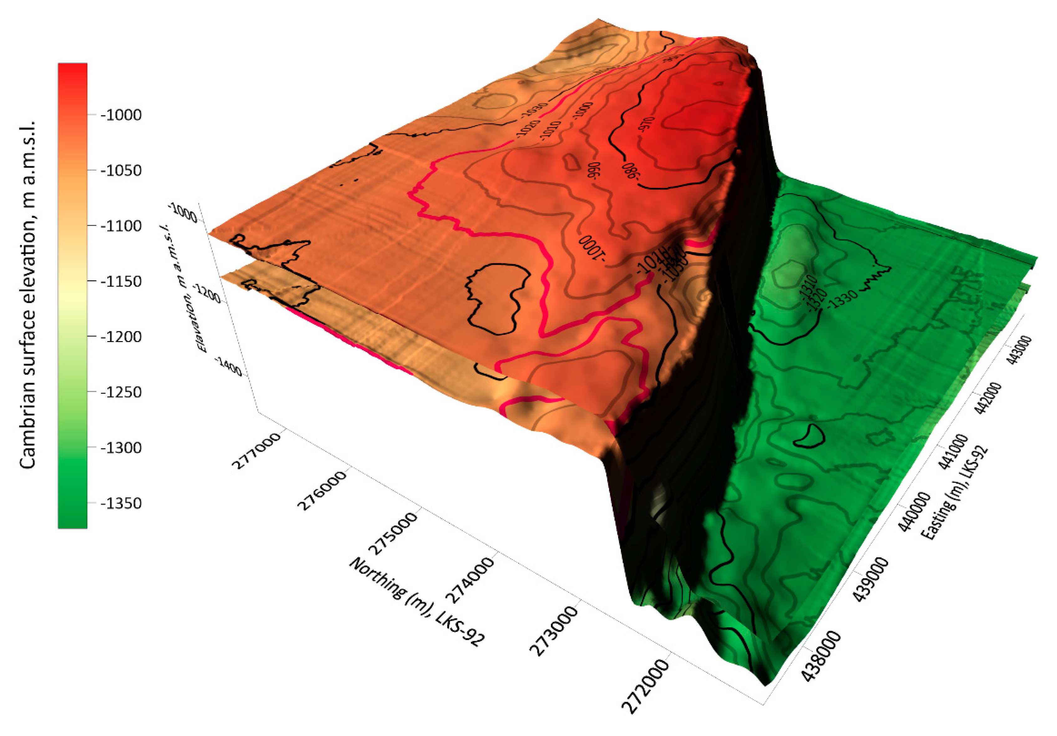
3.3. Geological Feasibility of the Dobele Structure for Fossil CO2 Geological Storage

Assessment of the geological characteristics of the Dobele structure and surrounding sediments was based on the available geological documentation and earlier work in the region. In 1970, the overall dimensions of Dobele high were verified by the application of the reflected wave method on the Palaeozoic sediments. From 1971 to 1972, the first exploration wells in the structure dome were drilled. They indicated the presence of sandstone with high collector properties [42]. The next wide-scale well-drilling was performed from 1987 to 1990 for the purposes of preparing a technological design for new underground gas storage. However, in the late 1990s and early 2000s, the major-scale studies of the Dobele structure were discontinued [42,73]. In 2008, the scientific interest in the structure as an underground gas storage site resumed [38,42,74]. The most recent hydrodynamic research of the structure was done in 2009. The results were based on the assessment and evaluation of the materials obtained in the time frame from 1987 to 1990, with new additional data on the well-pumping and piezometric level measurements [75]. These new data indicated the pumping volume flow rate from the structure wells in the range of 40–70 m2/day. This is the range of the average groundwater flow rate in Latvia. At the same time, the groundwater level in the structure does not correspond to the Cambrian groundwater level elsewhere in Latvia, because the existing wells are filled with reduced-pressure fluids due to well-rinsing during the research works in the past [75].
The Cambrian aquifer in the Baltic States is a zone of stagnant Na-Cl-type groundwater, rich in I+, Br2+ and other ions. The chemical composition of the saline groundwater is relatively unchanging throughout the aquifer. It contains NaCl and has an average mineralisation from 114 to 120 g/L [30,44,52,75]. The content of total dissolved solids (TDS) in water is in the range between 75 and 125 g/L, and the concentrations of Na+, Ca2+, and Cl- follow the increasing trends of TDS. The exact ionic concentrations, however, are subject to temporal changes and fluctuations [76]. The average ionic concentrations in the Cambrian aquifer system are 0–1.6 g/L for SO42- and 50–75 g/L for Cl-. The water temperature in the structure is 10–18 °C, which is not the best temperature range for CO2 storage in a supercritical stage (CO2 behaves as a supercritical fluid above its critical temperature of 31 °C), and the average pressure is 130 bar, which exceeds the suggested pressure regimen twice [30,44,52]. The filtration coefficient (K) of sandstone in the Dobele structure is 1.0–1.5 m/day, and the permeability of this sandstone is 1.3–1.9 D (Darcy units). A functional underground storage requires a permeability of at least 0.3 D, indicating that the Dobele structure meets the basic requirement for CO2 storage [75].
Storage of the fossil CO2 in an aquifer undergoes not only structural trapping, but also mineral trapping, which is the interaction between sediments in the structure and groundwater that becomes enriched with the injected CO2. This interaction leads to the formation of carbonates [41]. The fossil CO2 can be efficiently stored in the Cambrian sandstone of the Dobele structure thanks to its high collector properties.
The Dobele structure (Figure 3) consists of white to light grey, and fine to very fine-grained quartz sandstone, which is generally non-reactive to CO2. Moreover, a high NaCl content in the groundwater reduces the solubility of CO2 in water. The Cambrian sandstone contains clay, silt, and feldspar particles, which improve the effectiveness of the structure for permanent CO2 storage through intensive carbon mineralisation [20,42,44,57]. The sandstone consists of approximately 82% quartz, about 9% feldspar, 6% mica, and 3% various heavy metals, such as zircon, tourmaline, and rutile [44]. The reaction of Ca- and Mg-bearing aluminosilicates in the composition of the sandstone with the injected CO2 has a potential to form calcite, dolomite, and MgCO3 [77,78]. However, the interaction among aluminosilicates, carbonic acid, and newly formed carbonate minerals can reduce the overall salinity of the water and thus increase CO2 solubility [77,79].
Wet density of the sandstone within the Dobele structure increases with depth, the average being approximately 2300 kg/m3. The porosity and permeability, in turn, decrease with depth. According to the literature, the average estimated effective porosity of the sandstone in the structure is 20−25%, and the average permeability reaches 0.3−0.7 D. However, as proven by the experimental data from the hydrodynamic research in 2009, the actual permeability is much higher: 1.3−1.9 D, respectively [43,75]. The effective thickness of the aquifer, which is suitable for CO2 storage, is 70 m, in the depth range between 800 and 1100 m [30,43,44,52]. The permeability of the sandstone and the effective petrophysical properties of the structure, such as uniform composition, excellent storage, and filtration properties ensure CO2 injectivity to be economically practical and indicate that sufficient concentrations of CO2 can be retained. The structure is covered by Silurian clayey-carbonate sediments that ensure the tightness of the potential CO2 storage reservoir and prevents possible leakage, all of which in combination with mineralisation processes, greatly reduce any possible risks that could compromise safe and permanent CO2 storage in the structure [30,44,51,52].
The estimated CO2 storage potential in the Dobele structure is 56 Mt CO2, as determined in the EU Geo-capacity project [44,48]. However, when using Equation (1) designed for storage calculation in deep saline aquifers and a more optimistic approach and considering unexplored parts of the structure, the storage potential reaches 150 Mt CO2 [30,44,48]. The significant difference between the estimated and calculated storage capacities occurs due to high porosity and homogeneity of the structure, which allow to increase the storage efficiency factor [30,44,48]. Moreover, the latest calculations made by the authors include a larger area of the structure that also suggests a larger storage capacity.

3.4. Justification of Fossil CO2 Geological Storage in Latvia

The most prospective emissions for the CCS applications in the Baltic States are those produced by the energy industry—fuel combustion, as it accounts for most of the fossil CO2 [53]. The separation of carbon from flue gasses with the following capture is technologically more feasible than other approaches for CO2 emission reduction. If future emissions from the electricity and heat generation in the Baltic States remain in volumes like those of the present day or become lesser, then the capacity of the Latvian structures can secure storage of all the Baltic fossil CO2 produced by the energy industry sector for at least the next 22 years [32,41,47,48]. Moreover, due to the Paris Agreement, it is incumbent to use greener technologies and reduce the production of CO2 emissions [4,5]. This means that the time frame for CO2 storage can be significantly extended. Notably, if geological structures in Latvia were used only for the storage of locally produced fossil CO2 (thermal power plants), then they would secure storage for at least the next 200 years. The Dobele structure alone, with its estimated storage capacity of 56 Mt, could secure carbon storage for at least 30 years [38,40,41,42,43,44,47,48].
The economic justification of CO2 storage in saline aquifers is based on the price of carbon emissions. Placing a price on CO2 emissions not only imposes the obligation to implement more nature-friendly technologies in the industrial sector, but also produces significant co-benefits, such as reduced air pollution and the rise in public revenue [80]. Energy and economy models suggest that the deployment of CCS technologies is presently justifiable and becomes more relevant due to gradually increasing concerns for climate change and pricing of CO2 emissions [80,81,82]. In the present day, the carbon market price shows gradual increase. In May 2021, it was exceeding €50 per Mt CO2, which was the all-time maximum price [82]. In fact, much stringent emission reduction targets in the EU are set for 2030, which will increase the cost of emissions even more to meet tighter annual carbon caps [81]. Yet, the deployment of CCS systems on a large scale is unlikely in the absence of an explicit policy that substantially limits GHG emissions into the atmosphere [81]. Alternatively, with the GHG emission limits imposed, CCS systems can be competitive with other large-scale climate change mitigation options, such as the nuclear power and renewable energy technologies [81].
The economic evaluation of CO2 storage in geological structures should be based not only on the storage capacity, but also on the emissions in the region, sources of emissions, and the location of a potential storage site. For example, onshore storage will generally be less expensive and technologically easier to implement than offshore CO2 storage; carbon storage in shallow, high-permeability, depleted oil and gas reservoirs will cost less than storage in saline aquifers due to already existing infrastructure [83]. At the same time, the range of cost estimates for individual options is broad. In general, the cost difference between oil and gas reservoirs and saline aquifers is less pronounced than between onshore and offshore storage. Even though the Dobele structure contains a saline aquifer, it is discussed in the oil and gas sectors as a potential storage site [81]. A fundamental cost component for CO2 storage is wells for carbon injection, taking one of the largest shares in the total costs [84]. The cost of stored CO2 is determined by the cost of capture for a given emitter, transport to the storage site, and storage itself, which depends on the type of storage media [83].

3.5. Construction of a System of CO2 Delivery to the Geological Storage Sites

Deployment of CCS systems requires a significant amount of energy to be supplied to CO2 capture units, a variety of compressors and pumps, which can also generate thermal energy and electricity, and ensure safe CO2 storage in geological structures [85]. Therefore, a detailed evaluation of the technical and economic feasibility of a potential reservoir is of key importance.
The captured CO2 can be delivered to the storage units via pipelines or using road or water transport. Storage of the fossil CO2 in Latvian structures requires the construction of transport networks connecting the capture and storage sites that do not coincide. The CO2 transportation to underground structures in Latvia can be implemented via high-pressure piping systems, the cost of which is approximately proportional to the distance and terrain, while the construction process is like that of natural gas transmission pipelines [85]. However, the costs of CO2 and natural gas transmission pipelines can differ greatly due to the requirement for maintaining a higher pressure. Thus, the most rational and economically efficient placement of the network should be considered [86]. In Latvia, the piping system for CO2 transportation can be constructed alongside the already existing natural gas pipeline [87]. Possibilities and conditions for CO2 storage in the Dobele structure are favourable as the existing natural gas pipelines are located less than 10 km to the north and east of the structure [43,70]. The cost of employing a full CCS system from the emission sources to storage sites will be dominated by the cost of carbon capture. Thus, capturing emissions from the power industry with fossil-fired power plants will add to the cost of the produced electricity or heat. To be sure, if the cost of carbon storage prevails, it will also add to the cost of the electricity or heat [81].

4. Conclusions

The increase in CO2 concentration in the atmosphere has contributed to changes in the climate; thus, new solutions are required to limit its continuation. A negative impact on the climate and the ever-rising carbon price have made carbon storage underground into an economically justifiable option. The geological storage of CO2 could be considered as an efficient tool to achieve climate change mitigation aims, especially considering the EU Green Deal. Structures in Latvia have the highest potential for safe fossil CO2 storage in the Baltic States due to the natural geological history of the country. The re-evaluation of the potential for fossil CO2 storage in the Baltic States reflects 15 onshore Cambrian structures in saline groundwater aquifers, which can store from 600 to 1000 Mt CO2. At the current production rate of capturable CO2 emissions by the energy and manufacturing sectors of the country, the Latvian structures can provide storage for at least 150–250 years. These emissions are expected to decrease further, thus the service life of carbon traps can be significantly extended. The Dobele structure with its considerably large size, the thickness of 70 m, favourable petrophysical parameters, such as high porosity, and convenient location has one of the highest potentials for CO2 storage (150 Mt CO2) among all Latvian onshore structures identified up to date. The authors recommend further in-depth in situ research of the geological traps in Latvia, which is essential for the validation of the total storage capacity and deployment of CCS technologies.

Author Contributions

Conceptualisation, J.K., M.K., A.D., R.D. and V.S.; methodology, J.K. and A.D.; software, J.K. and A.D.; validation, J.K., A.D. and R.D.; formal analysis, J.K.; investigation, J.K. and A.D.; resources, J.K. and M.K.; data curation, J.K., M.K. and V.S.; writing—original draft preparation, J.K., A.D., M.K., R.D. and V.S.; writing—review and editing, J.K., A.D., M.K., R.D. and V.S.; visualisation, J.K. and A.D.; supervision, M.K. and V.S.; project administration, M.K. and R.D.; funding acquisition, M.K. All authors have read and agreed to the published version of the manuscript.

Funding

This research was funded by the European Regional Development Fund project “Innovation of the waste-to-energy concept for the low carbon economy: development of novel carbon capture technology for thermochemical processing of municipal solid waste (carbon capture and storage from waste—CCSW)”, grant number 1.1.1.1/19/A/013.

Institutional Review Board Statement

Not applicable.

Informed Consent Statement

Not applicable.

Data Availability Statement

The data presented in this study are available on request from the corresponding author.

Conflicts of Interest

The authors declare no conflict of interest. The funders had no role in the design of the study; in the collection, analysis, and interpretation of data; in the writing of the manuscript; and in the decision to publish the results.

References

  1. Trends in Atmospheric Carbon Dioxide. Global Monthly Mean CO2. Available online: https://www.esrl.noaa.gov/gmd/ccgg/trends/global.html (accessed on 18 May 2021).
  2. Friedlingstein, P.; O’Sullivan, M.; Jones, M.W.; Andrew, R.M.; Hauck, J.; Olsen, A.; Peters, G.P.; Peters, W.; Pongratz, J.; Sitch, S.; et al. Global Carbon Budget 2020. Earth Syst. Sci. Data 2020, 12, 3269–3340. [Google Scholar] [CrossRef]
  3. The Paris Agreement. Available online: https://treaties.un.org/doc/Publication/MTDSG/Volume%20II/Chapter%20XXVII/XXVII-7-d.en.pdf (accessed on 18 May 2021).
  4. Masson-Delmotte, V.; Zhai, P.; Pörtner, H.-O.; Roberts, D.; Skea, J.; Shukla, P.R.; Pirani, A.; Moufouma-Okia, W.; Péan, C.; Pidcock, R.; et al. Global Warming of 1.5°C. An IPCC Special Report on the Impacts of Global Warming of 1.5°C above Pre-Industrial Levels and Related Global Greenhouse Gas Emission Pathways, in the Context of Strengthening the Global Response to the Threat of Climate Change, Sustainable Development, and Efforts to Eradicate Poverty; Intergovernmental Panel on Climate Change: Geneva, Switzerland, 2019; p. 630. [Google Scholar]
  5. Fawzy, S.; Osman, A.I.; Doran, W.J.; Rooney, D.W. Strategies for mitigation of climate change: A review. Environ. Chem. Lett. 2020, 18, 2069–2094. [Google Scholar] [CrossRef]
  6. Baines, S.J.; Worden, R.H. Geological storage of carbon dioxide. Geol. Soc. Lond. Spéc. Publ. 2004, 233, 1–6. [Google Scholar] [CrossRef] [Green Version]
  7. Zhang, Z.; Huisingh, D. Carbon dioxide storage schemes: Technology, assessment and deployment. J. Clean. Prod. 2017, 142, 1055–1064. [Google Scholar] [CrossRef]
  8. USA. Department of Energy. Post-Combustion CO2 Capture. Available online: https://www.netl.doe.gov/coal/carbon-capture/post-combustion (accessed on 8 June 2021).
  9. USA. Department of Energy. Pre-Combustion Carbon Capture Research. Available online: https://www.energy.gov/fe/science-innovation/carbon-capture-and-storage-research/carbon-capture-rd/pre-combustion-carbon (accessed on 8 June 2018).
  10. Stanger, R.; Wall, T.; Spörl, R.; Paneru, M.; Grathwohl, S.; Weidmann, M.; Scheffknecht, G.; McDonald, D.; Myöhänen, K.; Ritvanen, J.; et al. Oxyfuel combustion for CO2 capture in power plants. Int. J. Greenh. Gas Control. 2015, 40, 55–125. [Google Scholar] [CrossRef]
  11. Manning, D.A.C.; Renforth, P. Passive sequestration of atmospheric CO2 through coupled plant-mineral reactions in urban soils. Environ. Sci. Technol. 2013, 47, 135–141. [Google Scholar] [CrossRef] [PubMed]
  12. Jorat, M.E.; Goddard, M.A.; Manning, P.; Lau, H.K.; Ngeow, S.; Sohi, S.P.; Manning, D.A.C. Passive CO2 removal in urban soils: Evidence from brownfield sites. Sci. Total Environ. 2020, 703, 135573. [Google Scholar] [CrossRef]
  13. Washbourne, C.L.; Lopez-Capel, E.; Renforth, P.; Ascough, P.L.; Manning, D.A.C. Rapid removal of atmospheric CO2 by urban soils. Environ. Sci. Technol. 2015, 49, 5434–5440. [Google Scholar] [CrossRef]
  14. Jo, H.K.; McPherson, G.E. Carbon storage and flux in urban residential greenspace. J. Environ. Manag. 1995, 45, 109–133. [Google Scholar] [CrossRef] [Green Version]
  15. Orr, F.M. Storage of carbon dioxide in geological formations. J. Pet. Technol. 2004, 56, 90–97. [Google Scholar] [CrossRef]
  16. Lashgari, H.R.; Sun, A.; Zhang, T.; Pope, G.A.; Lake, L.W. Evaluation of carbon dioxide storage and miscible gas EOR in shale oil reservoirs. Fuel 2019, 241, 1223–1235. [Google Scholar] [CrossRef]
  17. Bachu, S. Sequestration of CO2 in geological media: Criteria and approach for site selection in response to climate change. Energy Convers. Manag. 2000, 41, 953–970. [Google Scholar] [CrossRef]
  18. Metz, B.; Davidson, O.; de Coninck, H.; Loos, M.; Meyer, L. Carbon Dioxide Capture and Storage; Cambridge University Press: Cambridge, UK, 2005; p. 481. [Google Scholar]
  19. Urych, T.; Smolinski, A. Numerical modelling of CO2 migration in saline aquifers of selected areas in the upper Silesian coal basin in Poland. Energies 2019, 12, 3093. [Google Scholar] [CrossRef] [Green Version]
  20. Koteras, A.; Checko, J.; Urych, T.; Madziarczyk, M.; Smolinski, A. An assessment of the formations and structures suitable for safe CO2 geological storage in the upper Silesian coal basin in Poland in the context of the regulation relating to the CSS. Energies 2020, 13, 195. [Google Scholar] [CrossRef] [Green Version]
  21. Pu, H.; Wang, Y.; Li, Y. How CO2 storage mechanisms are different in organic shale: Characterization and simulation studies. SPE J. 2017, 3, 661–671. [Google Scholar] [CrossRef]
  22. Goldberg, D.S.; Takahashi, T.; Slagle, A.L. Carbon dioxide sequestration in deep-sea basalt. Proc. Natl. Acad. Sci. USA 2018, 105, 9920–9925. [Google Scholar] [CrossRef] [Green Version]
  23. Talapatra, A. A study on the carbon dioxide injection into coal seam aiming at enhancing coal bed methane (ECBM) recovery. J. Petrol. Explor. Prod. Technol. 2020, 10, 1965–1981. [Google Scholar] [CrossRef] [Green Version]
  24. Raza, A.; Gholami, R.; Rezaee, R.; Bing, C.H.; Nagarajan, R.; Hamid, M.A. CO2 storage in depleted gas reservoirs: A study on the effect of residual gas saturation. Petroleum 2018, 4, 95–107. [Google Scholar] [CrossRef]
  25. Duncan, D.C.; Swanson, V.E. Organic-Rich Shale of the United States and World Land Areas; Geological Survey: Washington, DC, USA, 1965; p. 30. [Google Scholar]
  26. Tomic, L.; Karovic-Maricic, V.; Danilovic, D.; Crnogorac, M. Criteria for CO2 storage in geological formations. Und. Min. Eng. 2018, 32, 61–67. [Google Scholar] [CrossRef]
  27. National Academies of Sciences, Engineering, and Medicine. Negative Emissions Technologies and Reliable Sequestrations: A Research Agenda; The National Academies Press: Washington, DC, USA, 2019; p. 510. [Google Scholar] [CrossRef]
  28. Bickle, M.J. Geological carbon storage. Nat. Geosci. 2009, 2, 815–818. [Google Scholar] [CrossRef]
  29. Cai, B.; Li, Q.; Liu, G.; Liu, L.; Jin, T.; Shi, H. Environmental concern-based site screening of carbon dioxide geological storage in China. Sci. Rep. 2017, 7, 7598. [Google Scholar] [CrossRef]
  30. Sliaupa, S.; Shogenova, A.; Shogenov, K.; Sliaupiene, R.; Zabele, A.; Vaher, R. Industrial carbon dioxide emissions and potential geological sinks in the Baltic States. Oil Shale 2008, 25, 465–484. [Google Scholar] [CrossRef] [Green Version]
  31. O’Brien, P.N.S. Aspects of seismic reflection prospecting for oil and gas. Geophys. J. Int. 1983, 74, 97–127. [Google Scholar] [CrossRef] [Green Version]
  32. Greenhouse Gas Emissions by Source Sector. Available online: http://appsso.eurostat.ec.europa.eu/nui/show.do?lang=en&dataset=env_air_gge (accessed on 18 May 2021).
  33. European Green Deal. Available online: https://ec.europa.eu/info/strategy/priorities-2019-2024/european-green-deal_en (accessed on 18 May 2021).
  34. Directive 2009/31/EC. Available online: https://eur-lex.europa.eu/legal-content/EN/TXT/?uri=CELEX%3A32009L0031 (accessed on 18 May 2021).
  35. CO2CRC Annual Report 2019–2020. Available online: https://co2crc.com.au/resources/reports/ (accessed on 18 May 2021).
  36. Chadwick, A.; Arts, R.; Bernstone, C.; May, F.; Thibeau, S.; Zweigel, P. Best Practice for the Storage of CO2 in Saline Aquifers-Observations and Guidelines from the SACS and CO2STORE Projects; British Geological Survey: Nottingham, UK, 2009; p. 267. [Google Scholar]
  37. Latvia CO2 Emissions. Available online: https://www.worldometers.info/co2-emissions/latvia-co2-emissions/ (accessed on 18 May 2021).
  38. Informatīvais Ziņojums “Par Iespējām Sekmēt Zemes Dzīļu Derīgo Īpašību Izmantošanu Valsts Ekonomiskā Potenciāla Paaugstināšanai”. Available online: http://tap.mk.gov.lv/mk/tap/?pid=30233795 (accessed on 18 May 2021).
  39. Beckholmen, M.; Tiren, S.A. The Geological History of the Baltic Sea: A Review of the Literature and Investigation Tools; Geosigma AB: Uppsala, Sweden, 2008; p. 103. [Google Scholar]
  40. Geological Settings and Structural Elements of the Baltic States. Available online: https://www4.meteo.lv/vgd_oil_page/geological_setting.htm (accessed on 18 May 2021).
  41. Shogenova, A.; Sliaupa, S.; Vaher, R.; Shogenov, K.; Pomeranceva, R. The Baltic Basin: Structure, properties of reservoir rocks, and capacity for geological storage of CO2. Est. J. Earth Sci. 2009, 58, 259–267. [Google Scholar] [CrossRef]
  42. Mikelsons, K.; Davis, A.; Zebergs, V.; Zeltins, N. Latvian Underground Gas Storage Facilities for the Development of a Safe Gas and Power Supply System of North European Gas. In Proceedings of the IAEE International Conference on Energy and Security in the Changing World, Teheran, Iran, 25–27 May 2004. [Google Scholar]
  43. Potential Sites for CO2 Geological Storage in Latvia. Available online: https://www.meteo.lv/fs/CKFinderJava/userfiles/files/Geologija/Potential%20sites.pdf (accessed on 18 May 2021).
  44. Shogenov, K.; Shogenova, A.; Vizika-Kavvadias, O. Petrophysical properties and capacity of prospective structures for geological storage of CO2 onshore and offshore Baltic. Energy Proced. 2013, 37, 5036–5046. [Google Scholar] [CrossRef] [Green Version]
  45. Jansons, L.; Zeltins, N. Technical Studies on Development of the Dobele Underground Natural Gas Storage Facility. In Proceedings of the REHVA Annual Conference on Advanced HVAC and Natural Gas Technologies, Riga, Latvia, 6–9 May 2015. [Google Scholar]
  46. Tuuling, I. The Leba Ridge-Riga-Pskov fault zone—a major East European Craton interior dislocation zone and its role in the early Paleozoic development of the platform cover. Est. J. Earth Sci. 2019, 68, 161–189. [Google Scholar] [CrossRef]
  47. Structural Traps in Latvia. Available online: https://www4.meteo.lv/vgd_oil_page/traps1.htm (accessed on 18 May 2021).
  48. Geological Survey of Denmark and Greenland. EU GeoCapacity: Assessing European Capacity for Geological Storage of Carbon Dioxide. Final Report; EU GeoCapacity Consortium: Copenhagen, Denmark, 2009; p. 66. [Google Scholar]
  49. Yang, X.; Buscheck, T.A.; Mansoor, K.; Wang, Z.; Carrol, S.A. Effectiveness of Geophysical Monitoring Methods in Detecting Brine and CO2 Leakage in Underground Sources of Drinking Water; Lawrence Livermore National Laboratory: Livermore, CA, USA, 2018; p. 30. [Google Scholar] [CrossRef]
  50. Oyedotun, T.D.T. X-ray fluorescence (XRF) in the investigation of the composition of earth materials: A review and an overview. Geol. Ecol. Land. 2018, 2, 148–154. [Google Scholar] [CrossRef]
  51. Llamas, B.; Arribas, M.; Hernandez, E.; Mazadiego, L.F. Pre-injection phase: Site selection and characterization. In CO2 Sequestration and Valorization; Morgado, C.R.V., Ed.; IntechOpen: Rijeka, Croatia, 2014; pp. 281–303. [Google Scholar]
  52. Shogenova, A.; Sliaupa, S.; Shogenov, K.; Sliaupiene, R.; Pomeranceva, R.; Vaher, R.; Uibu, M.; Kuusik, R. Possibilities for geological storage and mineral trapping of industrial CO2 emissions in the Baltic region. Energy Proc. 2009, 1, 2753–2760. [Google Scholar] [CrossRef] [Green Version]
  53. Global Emissions by Economic Sector. Available online: https://www.epa.gov/ghgemissions/global-greenhouse-gas-emissions-data (accessed on 18 May 2021).
  54. Global CCS Institute. Carbon Dioxide (CO2) Distribution Infrastructure. The Opportunities and Challenges Confronting CO2 Transport for Purposes of Carbon Capture and Storage (CCS) an Observation Paper; Global CCS Institute: Canberra, Australia, 2012; p. 43. [Google Scholar]
  55. OECD. Strategies to Reduce Greenhouse Gas Emissions from Road Transport: Analytical Methods; OECD Publishing: Paris, France, 2002; p. 67. [Google Scholar]
  56. Lithuania CO2 Emissions. Available online: https://www.worldometers.info/co2-emissions/lithuania-co2-emissions/ (accessed on 18 May 2019).
  57. Estonia CO2 Emissions. Available online: https://www.worldometers.info/co2-emissions/estonia-co2-emissions/ (accessed on 18 May 2021).
  58. EEA Greenhouse Gas-Data Viewer. Available online: https://www.eea.europa.eu/data-and-maps/data/data-viewers/greenhouse-gases-viewer (accessed on 18 May 2021).
  59. ACEA. CO2-Based Motor Vehicle Taxes in the European Union; ACEA Publishing: Brussels, Belgium, 2020; p. 5. [Google Scholar]
  60. Shogenova, A.; Shogenov, K.; Vaher, R.; Ivask, J.; Sliaupa, S.; Vangkilde-Pedersen, T.; Uibu, M.; Kuusik, R. CO2 geological storage capacity analysis in Estonia and neighbouring regions. Energy Proc. 2011, 4, 2785–2793. [Google Scholar] [CrossRef] [Green Version]
  61. Estonian Government. Estonian National Energy and Climate Plan (NECP 2030); Estonian Government: Tallinn, Estonia, 2019; p. 195. [Google Scholar]
  62. Paškevičius, J. The Geology of the Baltic Republics; University and Geological Survey of Lithuania: Vilnius, Lithuania, 1997; p. 387. [Google Scholar]
  63. Delina, A.; Kalvans, A.; Saks, T.; Bethers, U.; Vircavs, V. Highlights of Groundwater Research in the Baltic Artesian Basin; University of Latvia: Riga, Latvia, 2012; p. 15. [Google Scholar]
  64. Miller, R.D.; Saenz, V.; Huggins, R.J. Feasibility of CDP seismic reflection to image structures in a 220-m deep, 2-m thick coal zone near Palau, Coahila, Mexico. Geophysics 1992, 57, 1373–1380. [Google Scholar] [CrossRef]
  65. Raidla, V.; Kirsimae, K.; Bityukova, L.; Joeleht, A.; Shogenova, A.; Sliaupa, S. Lithology and diagenesis of the poorly consolidated Cambrian siliciclastic sediments in the northern Baltic sedimentary basin. Geol. Q. 2006, 50, 395–406. [Google Scholar]
  66. Gorecki, W.; Lapinskas, P.; Lashkova, L.; Lashkov, E.; Reicher, B.; Sakalauskas, K.; Strzetelski, W. Petroleum perspectives of the Baltic Syneclise. Pol. J. Miner. Resourc. 1992, 1, 65–88. [Google Scholar]
  67. Brangulis, A.; Kaņevs, S. Latvijas Tektonika; Rīgas Valsts Ģeoloģijas Dienests: Riga, Latvia, 2002; p. 710. [Google Scholar]
  68. Sliaupa, S.; Hoth, P.; Shogenova, A.; Huenges, E.; Rasteniene, V.; Freimanis, A.; Bityukova, L.; Joeleht, A.; Kirsimae, K.; Laskova, L.; et al. Characterization of Cambrian reservoir rocks and their fluids in the Baltic States (CAMBALTICA). In Cleaner Energy Systems through Utilization of Renewable Geothermal Energy Resources; Bujakowski, W., Ed.; Kajc: Krakow, Poland, 2003; pp. 61–73. [Google Scholar]
  69. Bergman, B.; Juhojuntti, N.G. Carbon Storage in Swedish Bedrock—Current Status Regarding Potential Storage Areas and Geophysical Information. In Proceedings of the Fall Meeting of the American Geophysical Union, San Francisco, CA, USA, 15 September 2010. [Google Scholar]
  70. Zemite, L.; Kutjuns, A.; Bode, I.; Kunickis, M.; Zeltins, N. Risk treatment and system recovery analysis of gas system of gas and electricity network of Latvia. Lat. J. Phys. Tech. Sci. 2018, 55, 3–15. [Google Scholar] [CrossRef] [Green Version]
  71. Jorgensen, P.; Ovlisen, F.R.; Catalini, E.; Petersen, N.; Muro-sune, N.; Littmann, W.; Hehmann, U. Inčukalns Underground Gas Storage—Study of Increased Flexibility and Use as Strategic Gas Storage. Summary; Ramboll: Copenhagen, Denmark, 2017; p. 6. [Google Scholar]
  72. The Outlook of Latvian Potential Underground Gas Storages and Prospects of Utilization of this Potential for Securing a Reliable Gas Supply to Europe. Available online: https://unece.org/fileadmin/DAM/ie/se/pdfs/wpgas/session/17_countr/latvia.pdf (accessed on 18 May 2021).
  73. Davis, A.; Jesinska, A.; Kreslins, A.; Zebergs, V.; Zeltins, N. Increasing Role of Underground Gas Storages for Reliable Supply of Gas to Latvia, Lithuania, Estonia, Finland and NW Russia and Prospects of Development of Inčukalns Underground Gas Storage. In Proceedings of the 23rd World Gas Conference, Amsterdam, The Netherlands, 5–9 June 2006. [Google Scholar]
  74. Regulations for Use of the Section of Subsoil of National Significance the “Dobele Structure”. Cabinet Regulation No. 524. Available online: http://extwprlegs1.fao.org/docs/pdf/lat186898ENG.pdf (accessed on 18 May 2021).
  75. Levins, I. Hidrodinamiskā Izpēte Valsts Nozīmes Zemes Nogabalā “Dobeles Struktūra”; PS ‘Dobeles Struktūra’: Riga, Latvia, 2010. [Google Scholar]
  76. Raidla, V.; Kirsimae, K.; Vaikmae, R.; Joeleht, A.; Karro, E.; Marandi, A.; Savitskaja, L. Geochemical evolution of groundwater in the Cambrian-Vendian aquifer system of the Baltic basin. Chem. Geol. 2009, 258, 219–231. [Google Scholar] [CrossRef]
  77. Shogenov, K.; Shogenova, A.; Vizika-Kavvadias, O.; Nauroy, J.F. Experimental modelling of CO2-fluid-rock interaction: The evolution of the composition and properties of host rocks in the Baltic region. Earth Space Sci. 2015, 2, 262–284. [Google Scholar] [CrossRef]
  78. Gunter, W.D.; Perkins, E.H.; Hutcheon, I. Aquifer disposal of acid gases: Modelling of water-rock reactions for trapping of acid wastes. Appl. Geochem. 2000, 15, 1086–1095. [Google Scholar] [CrossRef]
  79. Aszuba, J.P.; Janecky, D.R. Geochemical impacts of sequestering carbon dioxide in brine formations. In Carbon Sequestration and Its Role in the Global Carbon Cycle; McPherson, B.J., Sundquist, E.T., Eds.; AGU: Washington, DC, USA, 2009; Volume 183, pp. 239–247. [Google Scholar]
  80. OECD. Effective Carbon Rates on Energy; OECD Publishing: Paris, France, 2016; p. 16. [Google Scholar]
  81. Cost and Economic Potential of the CCS System. Available online: https://www.ipcc.ch/site/assets/uploads/2018/03/srccs_chapter8-1.pdf (accessed on 18 May 2021).
  82. Daily EU ETS Carbon Market Price (Euros). Available online: https://ember-climate.org/data/carbon-price-viewer/ (accessed on 18 May 2021).
  83. Schmelz, W.J.; Hochman, G.; Miller, K.G. Total cost of carbon capture and storage implemented at a regional scale: North-eastern and midwestern United States. Interface Focus 2020, 10, 10. [Google Scholar] [CrossRef] [PubMed]
  84. The International Energy Agency Greenhouse Gas R&D Programme. The Costs of CO2 Storage. Post-Demonstration CCS in the EU; European Technology Platform for Zero Emission Fossil Fuel Power Plants: Brussels, Belgium; p. 42. Available online: https://www.globalccsinstitute.com/archive/hub/publications/119816/costs-co2-storage-post-demonstration-ccs-eu.pdf (accessed on 18 May 2019).
  85. Gusca, J.; Blumberga, D. Simplified dynamic life cycle assessment model of CO2 compression, transportation and injection phase within carbon capture and storage. Energy Proc. 2011, 4, 2526–2532. [Google Scholar] [CrossRef] [Green Version]
  86. The International Energy Agency Greenhouse Gas R&D Programme. The Costs of CO2 Transport. Post-Demonstration CCS in the EU; European Technology Platform for Zero Emission fossil Fuel Power Plants: Brussels, Belgium; p. 53. Available online: https://www.globalccsinstitute.com/archive/hub/publications/119811/costs-co2-transport-post-demonstration-ccs-eu.pdf (accessed on 18 May 2021).
  87. Gusca, J. Research on Development of Latvian Energy Sector. Impact Assessment of Carbon Dioxide Capture and Storage Processes. Ph.D. Thesis, University of Latvia, Riga, Latvia, 2011. [Google Scholar]
Figure 1. Onshore and offshore structures in Latvia with a potential for CO2 storage exceeding 10 Mt. Source: authors design, based on Shogenova et al. (2009) [41].
Energies 14 03681 g001
Figure 2. The cross-section of the Baltic artesian basin. Source: authors’ design, based on Delina et al. (2012) [63].
Energies 14 03681 g002
Figure 3. A three-dimensional model of the Dobele structure (isoline of the max depth of the structure marked at −1020 m). Source: authors’ design, based on Levins (2010) [75].
Energies 14 03681 g003
Table 1. CO2 emissions (Mt) by the source sector in the Baltic States, 2018.
Source SectorEstoniaLatviaLithuaniaTotal
Public electricity and heat generation12.171.841.0215.03
Transport2.383.306.0011.68
Chemical industry--1.831.83
Petroleum refining--1.311.31
Manufacture of solid fuels1.560.050.051.66
Other fuel combustion sectors0.461.281.343.08
1 Based on greenhouse gas emissions by source sector [32].
Publisher’s Note: MDPI stays neutral with regard to jurisdictional claims in published maps and institutional affiliations.

