Article

Three-Phase PWM Inverter for Isolated Grid-Connected Renewable Energy Applications

by
Ahmed Ismail M. Ali
1,2,*,
Takaharu Takeshita
1 and
Mahmoud A. Sayed
2
1
Electrical and Mechanical Engineering Department, Nagoya Institute of Technology, Nagoya 466-8555, Japan
2
Electrical Engineering Department, South Valley University, Qena 83523, Egypt
*
Author to whom correspondence should be addressed.
Energies 2021, 14(12), 3701; https://doi.org/10.3390/en14123701
Submission received: 2 June 2021 / Revised: 16 June 2021 / Accepted: 17 June 2021 / Published: 21 June 2021

Abstract

:
This paper proposes a three-phase isolated flyback inverter (IFBI) for single-stage grid-tied solar PV applications, considering a simple sinusoidal pulse-width modulation (SPWM) scheme. The proposed single-stage inverter employs a reduced passive elements count by considering three input-parallel output-differential (IPOD) flyback converter modules. Additionally, a single small size LC-input low-pass filter is utilized at the input paralleling point for ripple-free input current operation, which is essential in grid-connected renewable energy applications. In addition, a mathematical model of the IFBI is presented to confirm the existence of its low-order harmonic components. A simple PI controller-based control scheme, considering only two loops and five sensors, is used to control the proposed grid-tied IFBI. Continuous modulation scheme (CMS) combined with SPWM is used to diminish the low-frequency harmonic components. Moreover, a simple selective harmonic elimination (SHE) loop is used for second-order harmonic components (SOHC) elimination from grid-injected currents. The SHE has decreased the SOHC from 43% to 0.96%, which improves the grid current THD from 39% to 3.65%, to follow the IEEE harmonic standard limits. Additionally, the harmonic elimination technique decreases the circulating power between the inverter paralleled modules, which enhances the grid currents power factor. The proposed inverter is verified through a grid-connected 200 V, 1.6 kW, 60 Hz experimental prototype, and the switching frequency is 50 kHz. TMS-based DSP controller is used to control the grid-injected power to follow the reference power set-point.

1. Introduction

Recently, renewable energy (especially photovoltaics) has maintained its expeditious expansion in many countries, which has paved the way for power electronics evolution. Many three-phase inverter topologies have been recommended in the literature [1,2,3]. Transformer-less inverter topologies have been extensively recommended [4,5,6,7], which require a boost converter on the input side to grasp the required voltage-gain [8]. Therefore, they have two stages, which increase the system complexity and cost. Additionally, they suffer from common-mode leakage current in many applications [9,10]. In addition, they may require transformers for high voltage-gain applications [11,12], which in turn increases the inverter cost, losses, and footprint. On the other hand, transformer-based inverters utilizing a line-frequency transformer for galvanic isolation reduces system efficiency and increases its footprint and cost. Owing to the persistent need for galvanic isolation in many applications, HFT-based inverters have emerged as an alternative for the line-frequency option offering reduced footprint and high-efficiency systems [13,14,15]. HFT-based inverters have been initiated by multi-stage architecture topologies utilizing a DC-link capacitor or inductor for decoupling purposes [16]. In addition, different multi-level inverter topologies have been developed for power quality and converter reliability improvements [17,18]. Additionally, modified inverter topologies are recommended in [14,15,19] that eliminate the DC decoupling capacitor/inductor. However, most of these topologies suffer from a high number of switches and system size, which increases the system cost and reduces the power density [20,21,22,23,24].
Motivated by the former drawbacks of multi-stage power inverters, single-stage differential inverter topologies have been recently proposed in single-phase and three-phase applications considering continuous input current operation [25,26,27,28,29,30,31,32,33,34,35,36]. In [36], an isolated single-stage MLI for standalone and grid-integrated solar PV applications was presented. These converter structures enhance the load/grid power quality; however, they require many power switches. Differential inverter topologies use DC-DC converter modules and are modulated by variable duty cycles [25]. In single-phase applications, a single-stage differential-based inverter was initiated and proposed in [28,35] considering boost-type converter modules. The differential buck inverter was investigated and analyzed in [34]. In order to combine buck and boost operations, a differential-based Cuk inverter was proposed [37]. In [37], a six-switch single-phase differential-based Cuk inverter was presented. However, it utilized increased switching devices that increased system footprint and cost. In [26,31], a single-phase differential-based Cuk inverter is presented for direct solar power conversion. The proposed topology enhances the system efficiency; however, it increases the input current ripples, which diminishes the system power factor. In three-phase applications, a single-stage differential inverter was recommended in [29], based on Cuk modules for PV applications. However, an increased passive elements count that affects the inverter footprint and cost is required. In [27], a four-switch three-phase SEPIC differential inverter is recommended. Although it reduces the number of required switches, this topology is limited in power applications due to the absence of galvanic isolation. In [38], a discontinuous modulation scheme for three-phase differential mode Cuk inverters was presented for circulating power minimization.
Among the different buck-boost topologies, the flyback converter has received much attention among researchers and industrial engineers due to the reduced passive elements utilization, in addition to its simple construction and control strategy [39,40,41,42,43]. In [39], a single-phase high-power interleaved flyback inverter was presented for PV applications. However, the system used a high transformer turns ratio to boost input voltage. Additionally, it used many parallel components for efficiency enhancement, which increased the system cost. In [40], a novel control scheme of a single-phase interleaved flyback inverter is presented for high-efficiency operation. However, the recommended control scheme is applicable for low-power operation. In [42], a down-sampled iterative-learning controller is proposed for CCM controlled single-phase inverters that achieves good steady-state response and acceptable system overshoot. However, the control strategy is more complicated and requires an unfolding circuit for two-stage operation. In [43], a boost/flyback based two-stage micro-inverter for solar PV systems was presented in order to enhance the transformer utilization. However, it loses the isolation property and requires the unfolding circuit for DC-AC conversion. In [41], a hybrid boost-flyback/flyback micro-inverter was introduced to reduce the transformer turn ratios, which decreases the leakage inductance and boosts the inverter efficiency. However, the presented topology did not consider galvanic isolation between DC and AC sides.
This paper presents a new three-phase, single-stage IFBI structure for grid-tied renewable energy applications, as shown in Figure 1. The proposed IFBI consists of three DC-DC flyback converter modules, which are paralleled on the input side sharing the same DC supply and differential-output on the grid side. The proposed IFBI offers a number of merits such as: reduced number of passive and switching components, voltage boosting/bucking capability in a single-stage operation, and control design simplicity. In addition, the proposed IFBI provides a galvanic isolation property for grid-tied applications due to the existence of HFTs. Additionally, the HFT winding turns ratio offers a wide flexibility for voltage boosting and bucking operations. In addition, the IFBI offers a continuous DC input current, which minimizes the capacitance over PV/fuel-cell systems and enhances their reliability [31]. For the proposed IFBI, a mathematical model is presented in order to confirm the negative sequence low-order harmonic components in the grid current waveforms, which requires a harmonic elimination control loop in order to meet grid standard requirements. Additionally, the proposed IFBI employs a low passive element number due to the usage of a single LC filter at the input DC side compared to other inverter structures that need individual LC filters at the input side of each module. Moreover, a simple PI controller-based control scheme, considering only two loops and five sensors, is used to control the proposed grid-tied IFBI. The CMS combined with SPWM is used to control the IFBI switches to mitigate low-order harmonics. The proposed IFBI is experimentally validated over 200 V, 1.6 kW, and switching frequency of 50 kHz prototype.

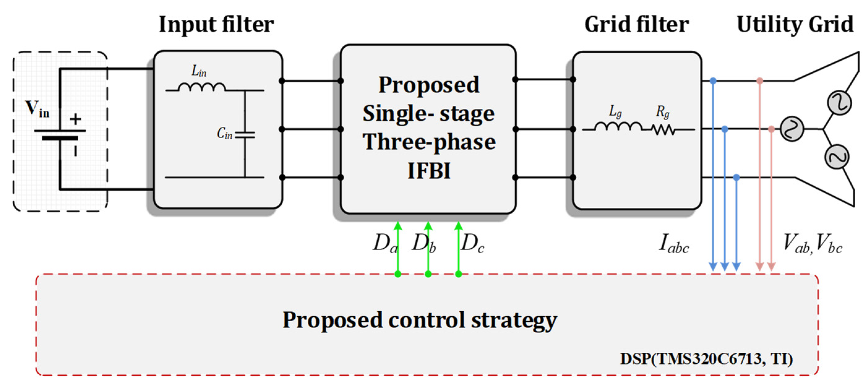
2. Proposed Single-Stage Three-Phase IFBI

2.1. Comparative Study

In this section, the proposed IFBI is compared with recent single-stage and two-stage inverter structures to investigate the main features of the three-phase single-stage IFBI for different applications. First, the proposed IFBI is compared with many recent inverter structures considering the voltage gain, number of inductors and capacitors, number of switches and diodes, existence of high-frequency isolation (HFI) and common-mode voltage (CMV), modular extension capability, power rating, and application, as listed in Table 1. Notably, the proposed IFBI requires a reduced number of passive and switching components for three-phase applications in comparison with the recent inverter structures. In addition, the IFBI provides voltage boosting/bucking capability and DC-AC conversion with galvanic isolation in a single-stage operation, which improves its power density and footprint. On the other side, Table 2 illustrates a fair comparison between the IFBI and counterpart inverter topologies considering the application, number of stages, power rating, voltage-gain, PWM, number of sensors, switching frequency, number of control-loops, efficiency, and switch ratings, respectively. It is worth mentioning that the IFBI configuration is controlled using a simple PI-based two-loop control scheme, which simplifies the mathematical calculations and reduces the execution time of the DSP controller. Moreover, the proposed structure offers improved efficiency and high-power operation in comparison with the existing flyback inverter structures. Additionally, it provides a galvanic isolation property via HFTs for grid protection requirements.

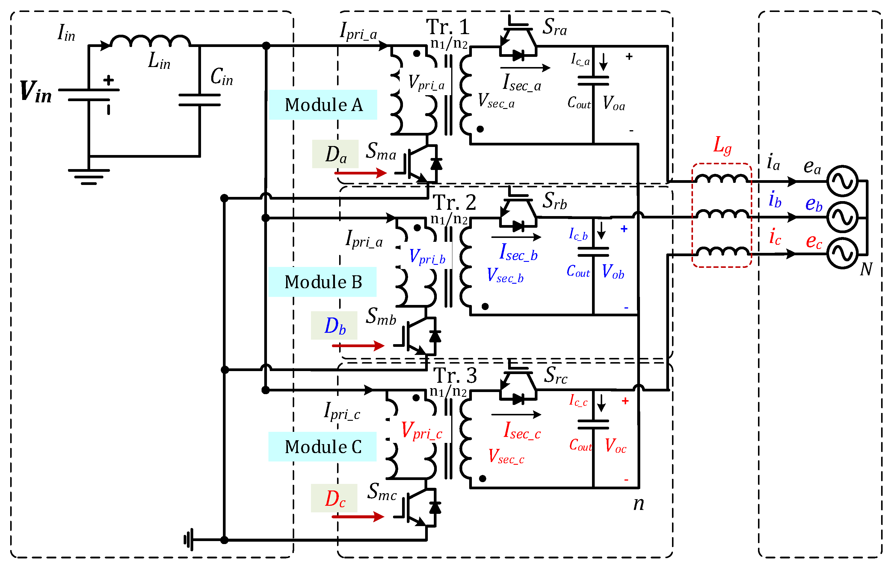
2.2. IFBI Circuit Configuration

Figure 1 shows the circuit configuration of the proposed IFBI that comprises three DC-DC flyback modules, which are connected in parallel at the DC input side and differentially connected at the grid side. Therefore, the proposed IFBI consists of six switches (SMa, SMb, SMc, SRa, SRb, SRc), three small output capacitors (Coa, Cob, Coc), three HFTs (Tr.1, Tr.2, and Tr.3), and a single LC input filter (Cin, Lin). In addition, IFBI provides continuous input current capability, which is very important from the reliability aspects in grid-tied applications due to the mitigation of high-capacity electrolytic capacitors [38]. Additionally, the proposed IFBI improves system reliability by utilizing a single LC input filter to reduce input current ripple, which directly influences system efficiency and power density. The power flow modes of a single module of the proposed IFBI (module A) are depicted in Figure 2. The power flows from DC side to grid during forward-operation mode and reverses during reversal operation mode, as cleared in Figure 2a. During the forward period, the main switch and synchronous switch body diode are sequentially switched ON and the power is injected to the grid. During reversal mode, the power reverses and flows into the IFBI module that causes the circulating power among the IFBI modules. Notably, Figure 2b,c illustrates the temporary operation of the proposed IFBI, whereas the power transfer occurs over a storage element. Hence, the HFT performs two functions: (1) energy storage and (2) galvanic isolation. Therefore, the input DC power is stored in the HFT during the main switch ON state, whereas the grid current is supported by the terminal capacitor of each IFBI module, as portrayed in Figure 2b. During the OFF state of the main switch, the stored energy in the HFT starts to flow through the secondary switch to supply the grid, as well as charge the terminal capacitor, as depicted in Figure 2c. Similarly, when the synchronous switch is turned ON, the reversed power stores in the HFT. The stored energy then releases through the main switch body diode when the synchronous switch is turned OFF.

2.3. IFBI Modulation Scheme and Mathematical Model

As illustrated in the former discussion, the IFBI operation depends on the flyback converter module by considering a wide range of variable duty cycles. The voltage conversion ratio of the flyback module can be expressed as follows [38,47]:
M o x = v o x V i n = i p r i , x i s e c , x = n D x 1 D x
where
  • vox: flyback converter output voltage (x = a, b, or c);
  • Vin: input DC voltage;
  • ipri,x: converter primary current;
  • isec,x: converter secondary current;
  • D: converter duty cycle;
  • n: transformer turns ratio (n = 1).
In addition, the converter total input DC current can be formulated as follows:
I i n = i i n , a + i i n , b + i i n , c = i p r i , a + i p r i , b + i p r i , c
According to Figure 1 and Figure 2, the balanced three-phase grid voltages and currents can be expressed as follows:
[ v a N ( t ) v b N ( t ) v c N ( t ) ] = 2 3 · E · [ sin ( ω t ) sin ( ω t 2 π 3 ) sin ( ω t + 2 π 3 ) ]
[ i a ( t ) i b ( t ) i c ( t ) ] = I m · [ sin ( ω t ) sin ( ω t 2 π 3 ) sin ( ω t + 2 π 3 ) ]
where, E and Im represent the grid line voltage and current RMS values, and   ω is the grid angular frequency.
As previously mentioned, the continuous modulation scheme (CMS) is used to control the proposed IFBI, in combination with static linearization strategy (SLS) to mitigate low-order harmonics. Therefore, three unipolar terminal voltages with 120° phase shift have been synthesized based on the duty cycles phase shift. Ideally, the same voltage offset can be generated on each module output, which can be cancelled by differential connection to supply the grid with sinusoidal voltages and currents. Based on (1), the module output voltage can be expressed as follows:
v o x ( t ) = M o x · V i n
where
  • x = a, b, or c;
  • Mox is the converter conversion ratio;
  • Vin is the DC input voltage.
The output voltages of the three converter modules can be formulated as follows:
[ v o a ( t ) v o b ( t ) v o c ( t ) ] = [ M o a M o b M o c ] · V i n
According to the converter output voltage and its sinusoidal envelope, the voltage conversion ratio has an AC component superimposed with DC offset component as follows:
[ M o a M o b M o c ] = M o x , d c + M o x , a c · [ sin ( ω t ) sin ( ω t 2 π 3 ) sin ( ω t + 2 π 3 ) ]
The DC component is maintained at the peak value of the sinusoidal component to minimize voltage stress over the circuit elements. Thus, it can be expressed as follows:
[ M o a M o b M o c ] = M + M · [ sin ( ω t ) sin ( ω t 2 π 3 ) sin ( ω t + 2 π 3 ) ] = M [ 1 + sin ( ω t ) 1 + sin ( ω t 2 π 3 ) 1 + sin ( ω t + 2 π 3 ) ]
where Mox,dc = Mox,ac = M.
From (1), (8); the duty cycle of each converter module can be expressed as follows:
D x = M ( 1 + K x ) 1 + M ( 1 + K x )
where Ka = sin(wt), Kb = sin(wt − 2π/3), Kc = sin(wt + 2π/3).
The output voltage from each module can also be expressed, based on (8), as follows:
[ v o a ( t ) v o b ( t ) v o c ( t ) ] = n M · V i n [ 1 + sin ( ω t ) 1 + sin ( ω t 2 π 3 ) 1 + sin ( ω t + 2 π 3 ) ]
According to (1) and (9); the converter primary input current can be formulated as follows:
i p r i , x ( t ) = 3 2 M i s e c , x ( t ) + 2 M K x i s e c , x ( t ) 1 2 M K x 1 i s e c , x ( t )
where Ka1 = cos[2(wt)], Kb1 = cos[2(wt − 2π/3)], Kc1 = cos[2(wt + 2π/3)].
Notably, considering the simple duty cycle formula in (1) and (9), the primary input current of the flyback converter module has three dominant components: the DC component, fundamental, and second-order harmonic components. Thus, a simple compensation loop is used for SOHC compensation for the grid-injected currents.
In addition, the input power to the proposed IFBI can be formulated, based on (11), as follows:
P i n , x ( t ) = 3 2 M V i n i s e c , x ( t ) + 2 M V i n K x i s e c , x ( t ) 1 2 M V i n K x 1 i s e c , x ( t )
Based on the former analysis of the proposed IFBI, Figure 3 shows the duty cycles (Da, Db, Dc), gating signals (SMa, Sra, SMb, Srb, SMc, Src), transformer voltage and current waveforms (VPri_a, IPri_a, VSec_a, ISec_b), capacitor current (ICa), and the grid voltages and current waveforms (vaN, vbN, vcN, ia, ib, ic) of a single module of the proposed IFBI. Hence, each module operates with a wide range of variable duty cycles, which provides voltage step-up/step-down capability.

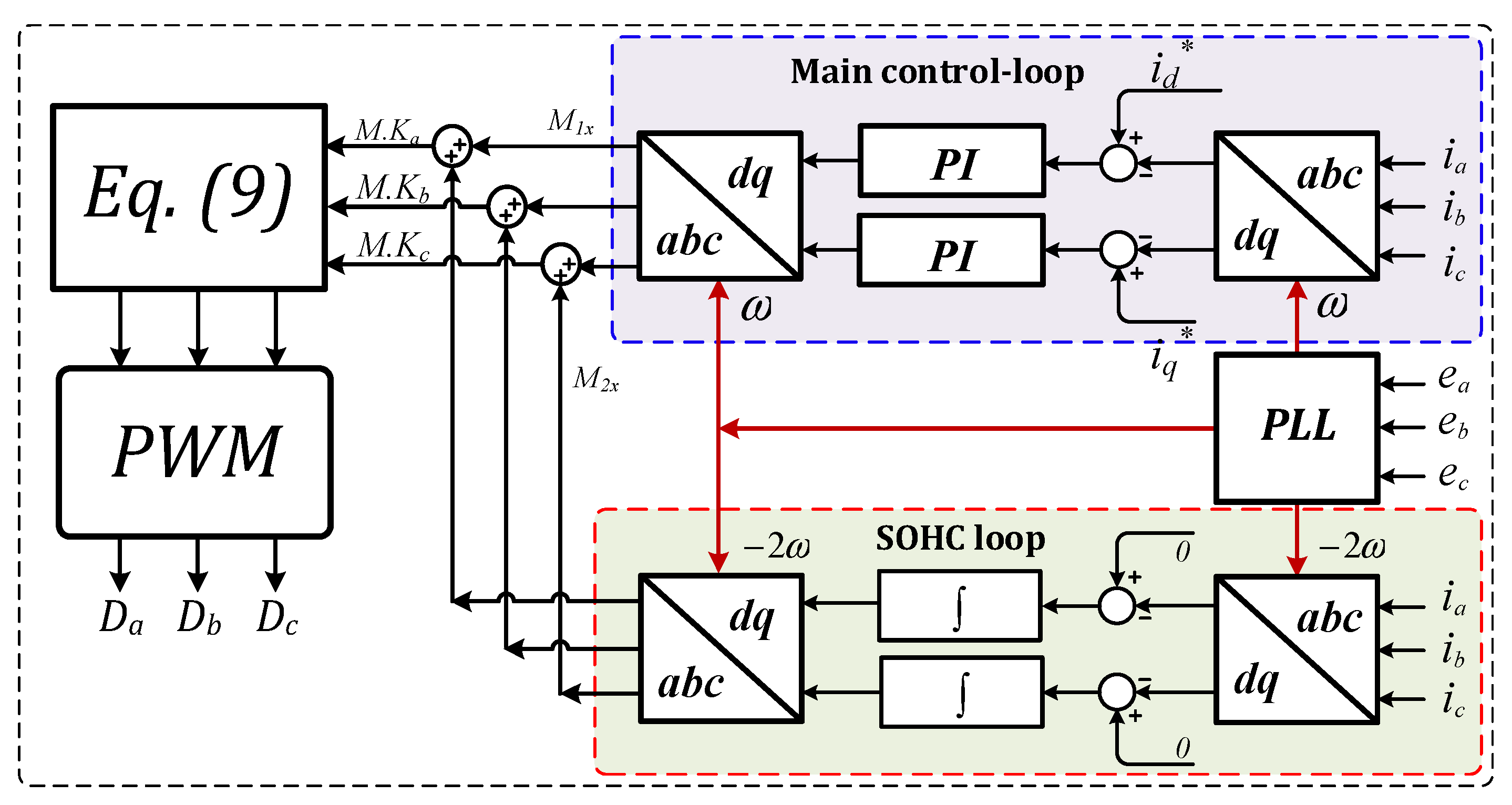
3. Proposed IFBI Control Strategy

As mentioned previously, the proposed IFBI is presented for grid-tied applications. A simple PI controller is used to control the proposed system for grid-injected power to follow the reference value. The control scheme of the proposed inverter is depicted in Figure 4, which consists of two control loops:
The main control loop (Loop1)
The SOHC elimination loop (Loop2)
Loop1 regulates the grid-injected currents of each module to follow its reference value. It is worth mentioning that the origin pole of the PI controller improves the closed loop DC gain of the IFBI, which limits the mismatches between flyback modules that minimize the circulating currents between inverter modules. Additionally, it enhances controller accuracy with the duty cycle variations. In addition, the compensator poles and zero boost phase margin (PM) of the IFBI that enhances system stability and reduces its resonance. The PI controller diminishes the error signal between the reference and actual grid currents, whereas its output signal is denoted as M1x. On the other side, the SHE loop (Loop2) is used to eliminate the SOHC that distorts the grid currents and causes the circulating power among the IFBI modules, which is confirmed in the harmonic modelling and analysis discussed in Section 2. The SOHC rotates in the reverse direction with double frequency (2ω), which is noticeable in the primary current envelope of each module. Therefore, a simple integrator is applied as a selective harmonic elimination (SHE) strategy for SOHC compensation. Loop2 extracts the SOHC, which is subtracted from the reference grid current, whereas the output signal from the integrator is denoted as M2x, as depicted in Figure 4. Thus, converter gain can be formulated as follows:
M K x = M 1 x + M 2 x
Moreover, the proposed control system poses a major challenge by considering only two control loops without the need to incur complex control systems that need long computational time and high controller specifications in comparison with the counterpart topologies such as [31].

4. System Results

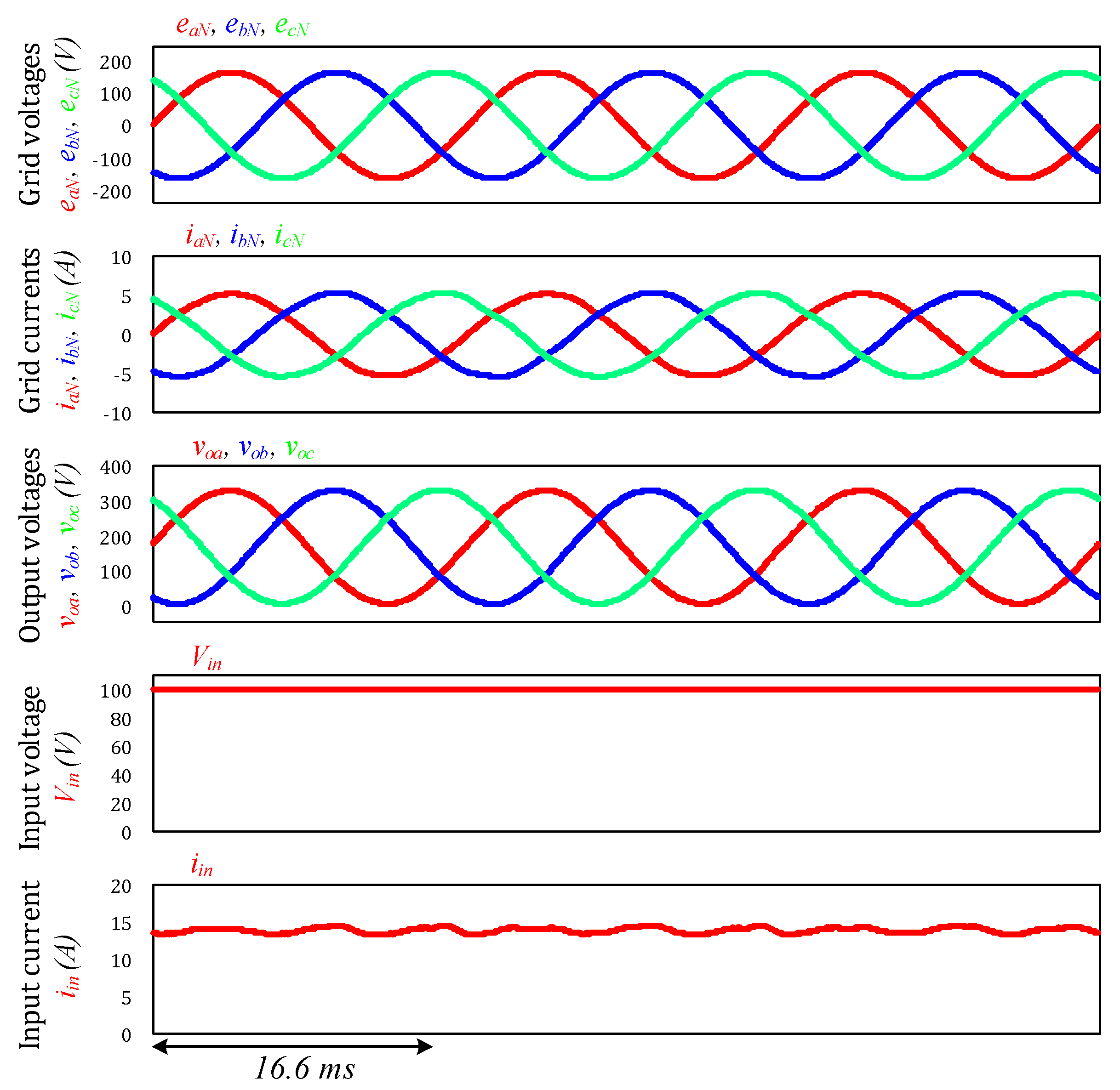
4.1. Simulation Results

The simulation findings of the proposed single-stage IFBI are confirmed at a rated converter power of 1.6 kW with the harmonic compensation technique, as shown in Figure 5. The three-phase voltage, currents, output voltage, DC input voltage, and DC input current are portrayed, respectively. With SOHC compensation, the compensation strategy eliminates the low-order harmonic component and supplies the grid with pure sinusoidal currents. In addition, it minimizes the input DC current ripples to 1.8%, which matches the IEEE harmonic standards.

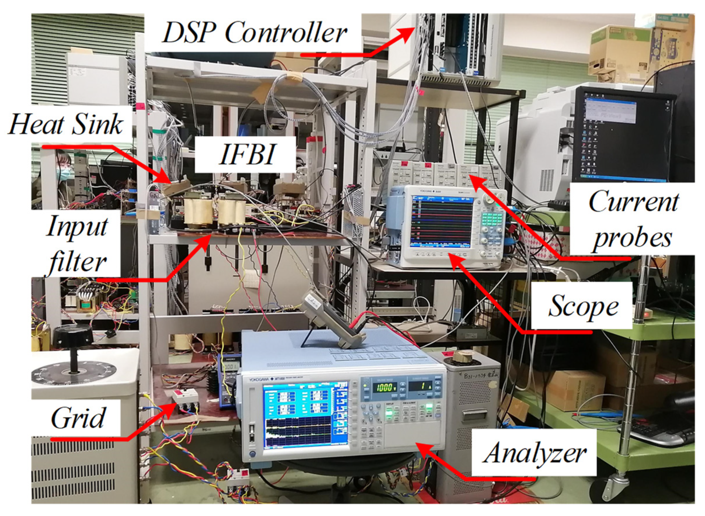
4.2. Experimental System Configuration

An IFBI laboratory prototype-based 200 V, 1.6 kW, and 60 Hz is built to investigate its validity for three-phase grid-connected applications. Figure 6 shows the system configuration and its control scheme. Additionally, the proposed experimental setup is portrayed via the photograph in Figure 7, whereas all system parameters are listed in Table 3. The system consists of a DC input supply, three-phase IFBI power stage, grid current filter, and the digital controller. It worth mentioning that N-channel SiC power MOSFET C2M0040120D has been used for both the primary and secondary sides of each flyback module during measurements of all experimental waveforms. The grid current is controlled to inject the rated power to the utility grid. The IFBI is investigated for grid-tied operation with SOHC compensation to compare the grid current distortion with standard permissible limits. The proposed control technique is built using a DSP (TMS320C6713, TI) digital controller. Based on the proposed control scheme and the IFBI mathematical model, a feedback control loop is used, which utilizes only two voltage sensors and three current sensors at the grid side for grid current regulation, as shown in Figure 4 and Figure 6. In addition, the system experimental waveforms are captured by a 16-channel DL-850 Yokogawa digital oscilloscope. Moreover, system efficiency and THD have been measured and analyzed by a WT1800 Yokogawa power analyzer.

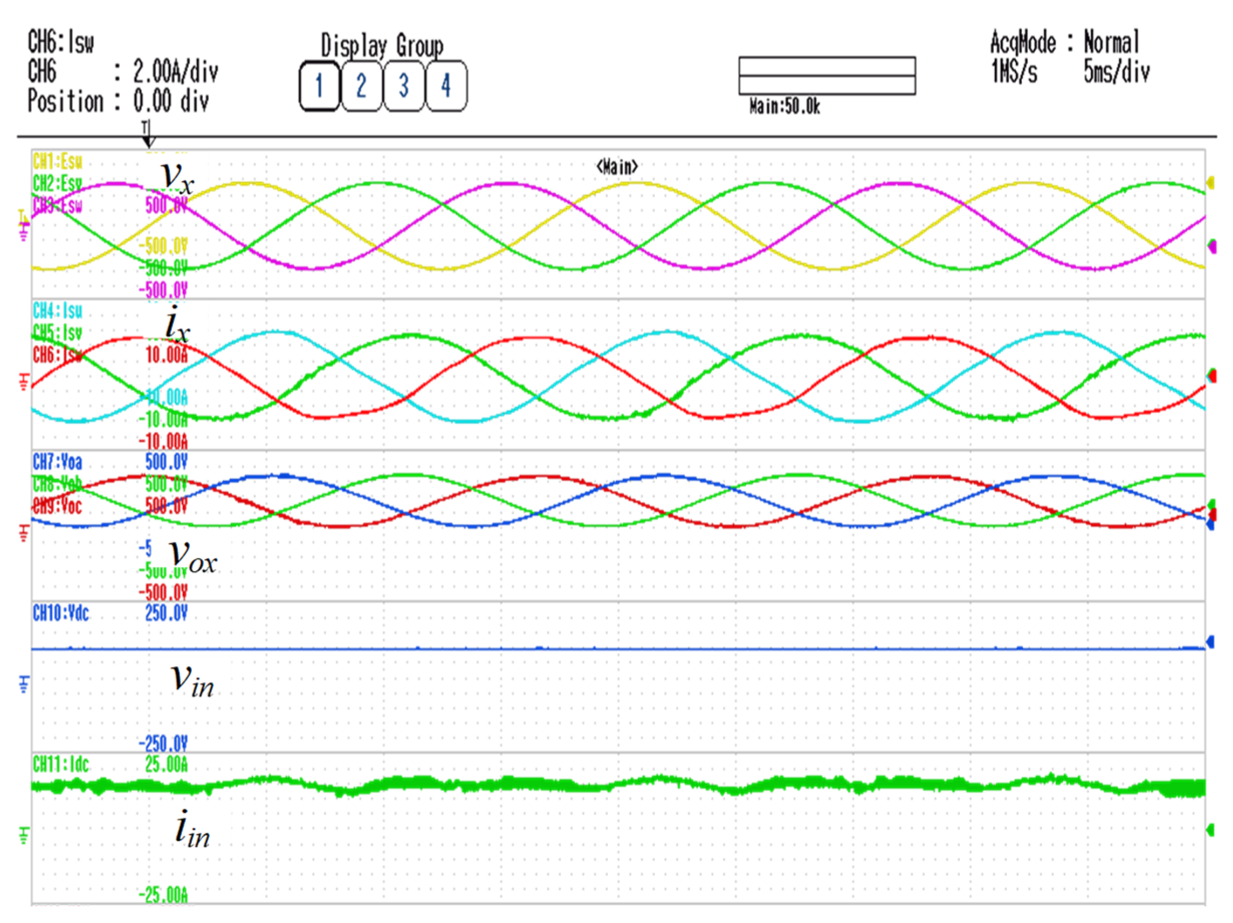
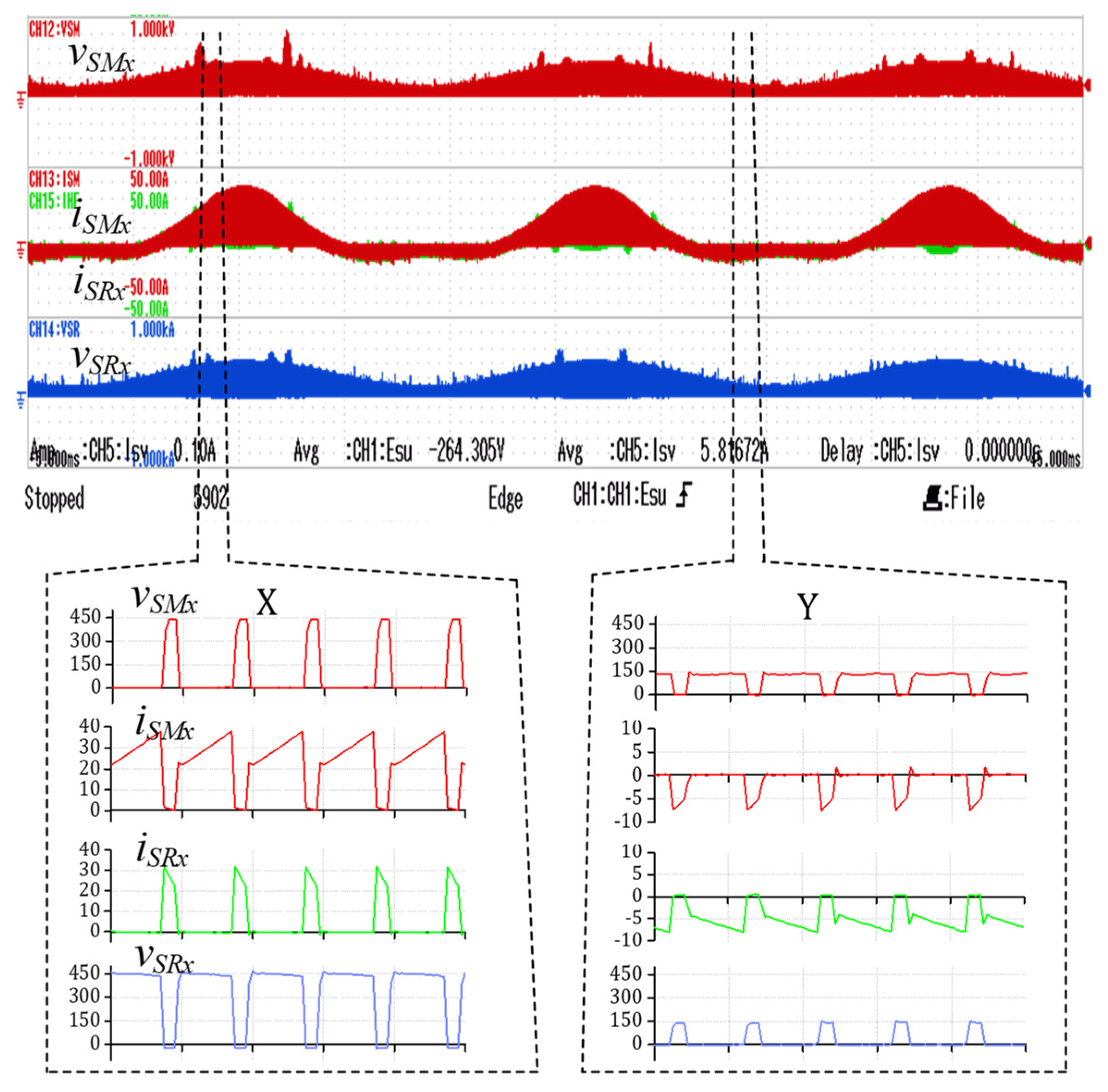
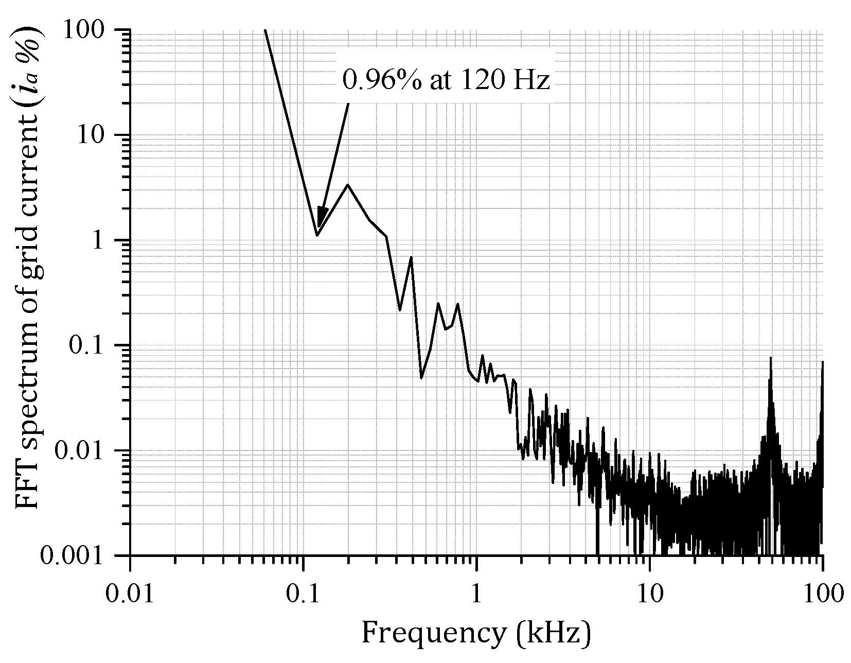
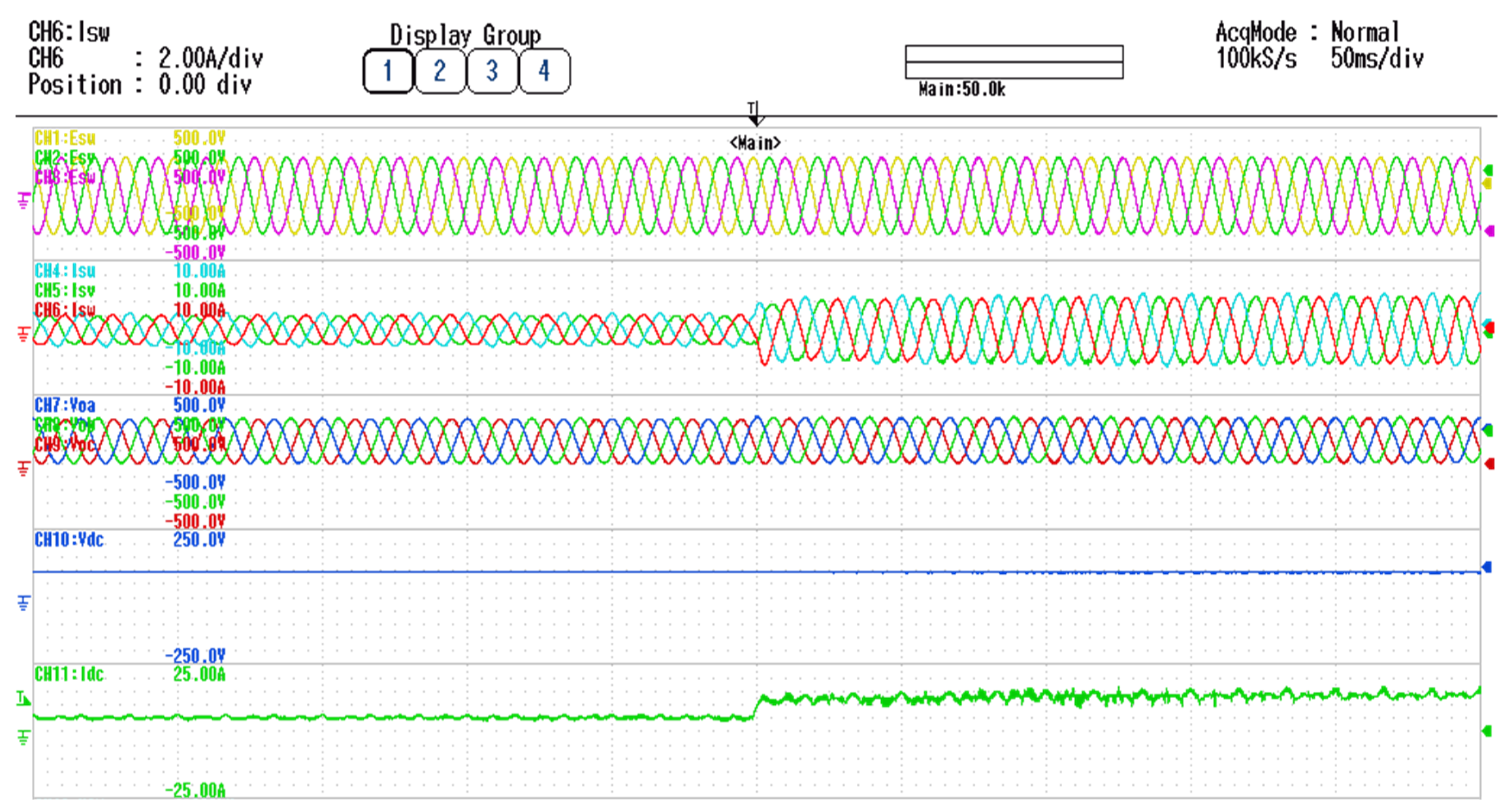
4.3. Experimental Results

The experimental system has been carried out considering the referenced grid-injected power of 1.6 kW with SOHC compensation. A unity power factor has been considered for grid-connected operation. Figure 8 shows the experimental results of the grid-tied IFBI with SOHC elimination at rated power of 1.6 kW. Figure 8 shows the three-phase grid voltage and current waveforms, output voltages across terminal capacitors, and DC input voltage and current, respectively. Evidently, and based on Figure 8, the IFBI supplies the grid by sinusoidal current waveforms with low THD contents. In addition, the proposed inverter performs voltage boosting of the input DC voltage as well as DC-AC voltage conversion through a single-stage operation, which improves the inverter power density and decreases its cost. In addition, the grid-injected power follows its reference value; this ensures the proposed controller operates well at the rated power flow. Additionally, the input DC current ripples have decayed, which forms an important feature in renewable energy applications. Moreover, the high-frequency switched waveforms of the proposed IFBI have been portrayed in Figure 9. The main switch voltage and current as well as the synchronous switch current and voltage are depicted, respectively, in Figure 9. In addition, the oscilloscope image of the IFBI experimental waveforms has two magnified sections (i.e., X and Y) for high-frequency switched waveforms at high and low duty cycles, respectively. Notably, with the SOHC elimination strategy, the ripples in the switched current waveforms of the main and synchronous switches have been reduced, which minimizes current stress of the inverter components, as shown in magnified sections X and Y. It worth mentioning that at the rated power flow, the synchronous switch voltage stress both with and without SOHC elimination is similar due to the rigid design of RC snubber circuit and the low HFT leakage inductance [47]. Additionally, it reveals the HFTs realistic design for high-power applications (i.e., 550 W), which exceeds the power ratings of existing flyback converters. Clearly, the experimental results of three-phase IFBI considering the two-loop control method display the successful operation of the IFBI to inject the reference grid power to the grid at unity-power factor.
At rated power flow of the proposed IFBI, considering SOHC compensation, the three-phase grid-injected currents are almost sinusoidal waveforms including low SOHC of 0.96%, which reduces the input DC peak-to-peak current ripple to 0.3 A, as shown in the grid current FFT harmonic spectrum in Figure 10. The peak-to-peak current ripple at the DC input side is 0.3 A, which is 1.8% of the DC input current that matches the IEEE harmonic standards. Table 4 shows the experimental results of the system measured via a Yokogawa power analyzer in case of SOHC compensation. THD of the grid-injected currents is 3.65% due to the elimination of the SOHC, which matches IEEE harmonic standards. Additionally, system overall efficiency at the rated power operation of 1.6 kW is 88% with SOHC. The experimental efficiency profile of the proposed IFBI is depicted in Figure 11 considering load variation from 0.2 to 1.6 kW. The operation of the proposed IFBI is stable with load variations that confirm the converter operation for various applications. Moreover, elimination of the SOHC enhances the system power factor at the grid side due to reduction in reactive power absorbed from the grid for sustaining the circulating power without SOHC elimination.
The performance of the proposed inverter control system has been verified by considering a step-change reference grid power to investigate the control system’s robustness. Figure 12 shows the system results for reference grid power flow changes from 0.5 kW to 1.6 kW with the SOHC elimination strategy. Notably, the grid power flow follows the reference level. The input DC current and grid-injected current waveforms are step-changed from their associated values at 0.5 kW and 1.6 kW considering a small settling time (i.e., 5 ms) without system overshoot. Clearly, the proposed control system with SOHC compensation strategy eliminates the third-order harmonic component from the input DC current for ripple-free input current, which is important in PV/fuel cell applications.
In addition, the different harmonic orders of grid-injected current are analyzed and compared with the IEEE-1547 harmonic standards at a rated power of 1.6 kW, as depicted in Figure 13. The DC component of the grid current is less than 0.2%, which follows the IEEE-1547 harmonics standard limit of 0.5%. In addition, the different harmonic orders of the grid-injected currents and IEEE standards are portrayed in Figure 13. Despite the existence of the second and fourth harmonic orders in the grid-injected currents, their values are less than the harmonic permissible limits. All low-order harmonics of grid-injected currents are less than the limits of IEEE permissible standard. Thus, the proposed IFBI and its control scheme improves the grid-injected power quality.

5. Conclusions

This paper has presented a three-phase single-stage grid-tied IFBI considering HFT for galvanic isolation and small passive elements compared with conventional three-phase inverters, which comparatively enhances the inverter power density. A detailed mathematical model of the proposed IFBI is presented to confirm the SOHC existence in the grid-injected currents. Moreover, a PI controller-based control scheme, considering only two loops and five sensors, is used to control the proposed grid-tied IFBI. A simple compensation strategy for the SOHC via integrator is utilized to minimize the THD of the grid-injected current. The integrator in the second control loop enriches the main control loop with the origin pole, which boosts the DC gain of the proposed inverter that enhances the system accuracy. Furthermore, the proposed control scheme simplifies the computational algorithm and enhances the DSP execution time. The proposed IFBI has been experimentally validated via a laboratory prototype for grid-tied application at 1.6 kW power flow. Experimental results prove the accuracy of the control technique in injecting sinusoidal current waveforms to the grid at unity power factor, in addition to elimination of the SOHC that decreases the THD of the grid current to 3.65%, which follows the permissible limits of the IEEE-1547 harmonic standards.

Author Contributions

Conceptualization, A.I.M.A.; methodology, A.I.M.A. and T.T.; software, A.I.M.A., T.T. and M.A.S.; validation, A.I.M.A., T.T. and M.A.S.; formal analysis, A.I.M.A.; investigation, A.I.M.A.; resources, A.I.M.A., T.T. and M.A.S.; data curation, A.I.M.A.; writing—original draft preparation, A.I.M.A.; writing—review and editing, A.I.M.A., T.T. and M.A.S.; visualization, A.I.M.A., T.T. and M.A.S. All authors have read and agreed to the published version of the manuscript.

Funding

This research received no external funding.

Institutional Review Board Statement

Not applicable.

Informed Consent Statement

Not applicable.

Data Availability Statement

Not applicable.

Conflicts of Interest

The authors declare no conflict of interest.

References

  1. Sun, P.; Liu, C.; Lai, J.-S.; Chen, C.-L.; Kees, N. Three-phase dual-buck inverter with unified pulsewidth modulation. IEEE Trans. Power Electron. 2011, 27, 1159–1167. [Google Scholar] [CrossRef]
  2. Deng, C.; Shu, Z.; Xia, Y.; Chen, N.; Wang, T.; Ma, H. In Three-Phase photovoltaic grid-connected inverter with LCL based on current deadbeat control and PI control. In Proceedings of the 2014 International Conference on Power System Technology, Chengdu, China, 20–22 October 2014; pp. 2864–2870. [Google Scholar]
  3. Ali, A.I.; Sayed, M.A.; Mohamed, E.E. Modified efficient perturb and observe maximum power point tracking technique for grid-tied PV system. Int. J. Electr. Power Energy Syst. 2018, 99, 192–202. [Google Scholar] [CrossRef]
  4. Chen, J.-J.; Kung, C.-M. A new on-chip all-digital three-phase full-bridge dc/ac power inverter with feedforward and frequency control techniques. IEEE Trans. Ultrason. Ferroelectr. Freq. Control. 2010, 57, 1915–1925. [Google Scholar] [CrossRef]
  5. Zhang, L.; Waite, M.J.; Chong, B. Three-Phase four-leg flying-capacitor multi-level inverter-based active power filter for unbalanced current operation. IET Power Electron. 2013, 6, 153–163. [Google Scholar] [CrossRef]
  6. Ali, A.I.M.; Sayed, M.A.; Mohamed, A.A. Seven-Level Inverter with Reduced Switches for PV System Supporting Home-Grid and EV Charger. Energies 2021, 14, 2718. [Google Scholar] [CrossRef]
  7. Ali, A.I.; Mohamed, E.E.; Sayed, M.A.; Saeed, M.S.; Azmy, A.M. In Design and Validation of a Single Phase Multilevel Inverter Utilizing Reduced Switches Number. In Proceedings of the 2018 20th International Middle East Power Systems Conference (MEPCON), Cairo, Egypt, 18–20 December 2018; pp. 974–979. [Google Scholar]
  8. Gao, F.; Loh, P.C.; Teodorescu, R.; Blaabjerg, F.; Vilathgamuwa, D.M. Topological design and modulation strategy for buck–boost three-level inverters. IEEE Trans. Power Electron. 2009, 24, 1722–1732. [Google Scholar] [CrossRef]
  9. Yang, B.; Li, W.; Gu, Y.; Cui, W.; He, X. Improved transformerless inverter with common-mode leakage current elimination for a photovoltaic grid-connected power system. IEEE Trans. Power Electron. 2011, 27, 752–762. [Google Scholar] [CrossRef]
  10. Freddy, T.K.S.; Rahim, N.A.; Hew, W.-P.; Che, H.S. Modulation techniques to reduce leakage current in three-phase transformerless H7 photovoltaic inverter. IEEE Trans. Ind. Electron. 2014, 62, 322–331. [Google Scholar] [CrossRef]
  11. Rezaei, M.A.; Lee, K.-J.; Huang, A.Q. A high-efficiency flyback micro-inverter with a new adaptive snubber for photovoltaic applications. IEEE Trans. Power Electron. 2015, 31, 318–327. [Google Scholar] [CrossRef]
  12. Feloups, C.E.; Ali, A.I.; Mohamed, E.E. In Design of single-phase seven-level inverter with reduced number of switching devices for PV applications. In Proceedings of the 2017 19th International Middle East Power Systems Conference (MEPCON), Cairo, Egypt, 19–21 December 2017; pp. 817–822. [Google Scholar]
  13. Pomilio, J.A.; Spiazzi, G. High-Precision current source using low-loss, single-switch, three-phase AC/DC converter. IEEE Trans. Power Electron. 1996, 11, 561–566. [Google Scholar] [CrossRef]
  14. Chunkag, V.; Kamnarn, U. Parallelling three-phase AC to DC converter using CUK rectifier modules based on power balance control technique. IET Power Electron. 2010, 3, 511–524. [Google Scholar] [CrossRef]
  15. Schenk, K.; Cuk, S. In A simple three-phase power factor corrector with improved harmonic distortion, PESC97. In Proceedings of the Record 28th Annual IEEE Power Electronics Specialists Conference. Formerly Power Conditioning Specialists Conference 1970–71, Power Processing and Electronic Specialists Conference 1972, St. Louis, MO, USA, 27–27 June 1997; pp. 399–405. [Google Scholar]
  16. Wang, L.; Chen, H.-W.; Lee, D.-J. In Implementation of a DSP-based power converter for a wind induction generator. In Proceedings of the 2008 IEEE Power and Energy Society General Meeting-Conversion and Delivery of Electrical Energy in the 21st Century, Pittsburgh, PA, USA, 20–24 July 2008; pp. 1–6. [Google Scholar]
  17. Tehrani, K.A.; Andriatsioharana, H.; Rasoanarivo, I.; Sargos, F. In A novel multilevel inverter model. In Proceedings of the 2008 IEEE Power Electronics Specialists Conference, Rhodes, Greece, 15–19 June 2008; pp. 1688–1693. [Google Scholar]
  18. Mohammadhassani, A.; Teymouri, A.; Mehrizi-Sani, A.; Tehrani, K. In Performance Evaluation of an Inverter-Based Microgrid under Cyberattacks. In Proceedings of the 2020 IEEE 15th International Conference of System of Systems Engineering (SoSE), Budapest, Hungary, 2–4 June 2020; pp. 211–216. [Google Scholar]
  19. Ali, A.I.M. Techniques for Photovoltaic Generation; South Valley University: Qena, Egypt, 2017. [Google Scholar]
  20. Suresh, Y.; Panda, A.; Mahesh, M. In an improved performance of cascaded multilevel inverter with single DC source by employing three-phase transformers. In Proceedings of the 2010 Conference Proceedings IPEC, Singapore, 27–29 October 2010; pp. 1088–1093. [Google Scholar]
  21. Ali, A.I.; Sayed, M.A.; Mohamed, E.E.; Azmy, A.M. Advanced single-phase nine-level converter for the integration of multiterminal DC supplies. IEEE J. Emerg. Sel. Top. Power Electron. 2018, 7, 1949–1958. [Google Scholar] [CrossRef]
  22. Davoodnezhad, R.; Holmes, D.G.; McGrath, B.P. A novel three-level hysteresis current regulation strategy for three-phase three-level inverters. IEEE Trans. Power Electron. 2013, 29, 6100–6109. [Google Scholar] [CrossRef]
  23. Ali, A.I.M.; Sayed, M.A.; Takeshita, T.; Hassan, A.M.; Azmy, A.M. A single-phase modular multilevel inverter based on controlled DC-cells under two SPWM techniques for renewable energy applications. Int. Trans. Electr. Energy Syst. 2021, 31, e12599. [Google Scholar] [CrossRef]
  24. Hassan, A.M.; Yang, X.; Ali, A.I.; Ahmed, T.A.; Azmy, A.M. In A Study of Level-Shifted PWM Single-phase 11-Level Multilevel Inverter. In Proceedings of the 2019 21st International Middle East Power Systems Conference (MEPCON), Cairo, Egypt, 17–19 December 2019; pp. 170–176. [Google Scholar]
  25. Williams, B.W. DC-to-DC converters with continuous input and output power. IEEE Trans. Power Electron. 2012, 28, 2307–2316. [Google Scholar] [CrossRef]
  26. Mazumder, S.K.; Mehrnami, S. In A low-device-count single-stage direct-power-conversion solar microinverter for microgrid. In Proceedings of the 2012 3rd IEEE International Symposium on Power Electronics for Distributed Generation Systems (PEDG), Aalborg, Denmark, 25–28 June 2012; pp. 725–730. [Google Scholar]
  27. Diab, M.S.; Elserougi, A.; Massoud, A.M.; Abdel-Khalik, A.S.; Ahmed, S. A four-switch three-phase SEPIC-based inverter. IEEE Trans. Power Electron. 2014, 30, 4891–4905. [Google Scholar] [CrossRef]
  28. Caceres, R.O.; Barbi, I. A boost DC-AC converter: Analysis, design, and experimentation. IEEE Trans. Power Electron. 1999, 14, 134–141. [Google Scholar] [CrossRef]
  29. Darwish, A.; Holliday, D.; Ahmed, S.; Massoud, A.M.; Williams, B.W. A single-stage three-phase inverter based on Cuk converters for PV applications. IEEE J. Emerg. Sel. Top. Power Electron. 2014, 2, 797–807. [Google Scholar] [CrossRef]
  30. Ali, A.I.M.; Sayed, M.A.; Takeshita, T. Isolated single-phase single-stage DC-AC cascaded transformer-based multilevel inverter for stand-alone and grid-tied applications. Int. J. Electr. Power Energy Syst. 2021, 125, 106534. [Google Scholar] [CrossRef]
  31. Kulkarni, A.; Gupta, A.; Mazumder, S.K. Resolving practical design issues in a single-phase grid-connected GaN-FET-based differential-mode inverter. IEEE Trans. Power Electron. 2017, 33, 3734–3751. [Google Scholar] [CrossRef]
  32. Darwish, A.; Massoud, A.M.; Holliday, D.; Ahmed, S.; Williams, B. Single-Stage three-phase differential-mode buck-boost inverters with continuous input current for PV applications. IEEE Trans. Power Electron. 2016, 31, 8218–8236. [Google Scholar] [CrossRef] [Green Version]
  33. Mehrnami, S.; Mazumder, S.K. Discontinuous modulation scheme for a differential-mode Ćuk inverter. IEEE Trans. Power Electron. 2014, 30, 1242–1254. [Google Scholar] [CrossRef]
  34. Chen, D.; Wang, G. Differential buck DC–DC chopper mode inverters with high-frequency link. IEEE Trans. Power Electron. 2010, 26, 1444–1451. [Google Scholar] [CrossRef]
  35. Liu, H. Control Design of a Single-Phase Dc/Ac Inverter for PV Applications; University of Arkansas: Fayetteville, NC, USA, 2016. [Google Scholar]
  36. Ali, A.I.M.; Sayed, M.A.; Takeshita, T. In New Cascaded-Transformers Multilevel Inverter for Renewable Distribution Systems. In Proceedings of the 2020 IEEE Energy Conversion Congress and Exposition (ECCE), Detroit, MI, USA, 11–15 October 2020; pp. 3965–3971. [Google Scholar]
  37. Knight, J.; Shirsavar, S.; Holderbaum, W. An improved reliability Cuk based solar inverter with sliding mode control. IEEE Trans. Power Electron. 2006, 21, 1107–1115. [Google Scholar] [CrossRef]
  38. Mehrnami, S.; Mazumder, S.K.; Soni, H. Modulation scheme for three-phase differential-mode Ćuk inverter. IEEE Trans. Power Electron. 2015, 31, 2654–2668. [Google Scholar] [CrossRef]
  39. Tamyurek, B.; Kirimer, B. An interleaved high-power flyback inverter for photovoltaic applications. IEEE Trans. Power Electron. 2014, 30, 3228–3241. [Google Scholar] [CrossRef]
  40. Lodh, T.; Pragallapati, N.; Agarwal, V. Novel control scheme for an interleaved flyback converter based solar PV microinverter to achieve high efficiency. IEEE Trans. Ind. Appl. 2018, 54, 3473–3482. [Google Scholar] [CrossRef]
  41. Zhang, F.; Xie, Y.; Hu, Y.; Chen, G.; Wang, X. A hybrid boost–flyback/flyback microinverter for photovoltaic applications. IEEE Trans. Ind. Electron. 2019, 67, 308–318. [Google Scholar] [CrossRef]
  42. Kim, H.; Lee, J.S.; Kim, M. Downsampled iterative learning controller for flyback CCM inverter. IEEE Trans. Ind. Electron. 2017, 65, 510–520. [Google Scholar] [CrossRef]
  43. Shitole, A.B.; Sathyan, S.; Suryawanshi, H.; Talapur, G.G.; Chaturvedi, P. Soft-Switched high voltage gain boost-integrated flyback converter interfaced single-phase grid-tied inverter for SPV integration. IEEE Trans. Ind. Appl. 2017, 54, 482–493. [Google Scholar] [CrossRef]
  44. Cecati, C.; Dell’Aquila, A.; Liserre, M. A novel three-phase single-stage distributed power inverter. IEEE Trans. Power Electron. 2004, 19, 1226–1233. [Google Scholar] [CrossRef]
  45. Diab, M.S.; Elserougi, A.; Abdel-Khalik, A.S.; Massoud, A.M.; Ahmed, S. In Modified modulation scheme for photovoltaic fed grid-connected three-phase boost inverter. In Proceedings of the IECON 2013—39th Annual Conference of the IEEE Industrial Electronics Society, Vienna, Austria, 10–13 November 2013; pp. 1735–1740. [Google Scholar]
  46. Zeng, J.; Lin, W.; Liu, J. Switched-Capacitor-Based active-neutral-point-clamped seven-level inverter with natural balance and boost ability. IEEE Access 2019, 7, 126889–126896. [Google Scholar] [CrossRef]
  47. Erickson, R.W.; Maksimovic, D. Fundamentals of Power Electronics; Springer Science & Business Media: Berlin/Heidelberg, Germany, 2007. [Google Scholar]
Figure 1. Three-phase single-stage isolated flyback inverter.
Energies 14 03701 g001
Figure 2. Temporary power transfer in a single module of the IFBI.
Energies 14 03701 g002
Figure 3. Proposed IFBI PWM control strategy.
Energies 14 03701 g003
Figure 4. Closed-loop control scheme of the proposed IFBI.
Energies 14 03701 g004
Figure 5. IFBI simulation results with SOHC compensation strategy.
Energies 14 03701 g005
Figure 6. Proposed IFBI control scheme.
Energies 14 03701 g006
Figure 7. Proposed IFBI photograph.
Energies 14 03701 g007
Figure 8. Experimental results of the proposed IFBI with SOHC at 1.6 kW.
Energies 14 03701 g008
Figure 9. Experimental high-frequency switched waveforms of the proposed IFBI with SOHC compensation at 1.6 kW.
Energies 14 03701 g009
Figure 10. Grid current FFT harmonic spectrum with SOHC compensation at 1.6 kW.
Energies 14 03701 g010
Figure 11. Efficiency profile of the IFBI under load variation.
Energies 14 03701 g011
Figure 12. Experimental results of the IFBI during step-changed grid-injected power from 0.5 kW to 1.6 kW.
Energies 14 03701 g012
Figure 13. Grid current harmonic orders in comparison to IEEE-1547 harmonic standards.
Energies 14 03701 g013
Table 1. Comparison of IFBI with recent inverter structures.
TopologyVoltage-gainInductor No.
Capacitor No.
Switch No.
Diodes No.
HFI
CMV
Operation ModularityPower Rating (kW)Application
Ref. [28]Boost2
2
4
0
No
NA
No0.5Single-phase
Ref. [44]Buck-Boost3
3
6
0
No
NA
Yes1.4Three-phase
Ref. [45]Buck 3
3
4
0
No
NA
Yes0.4Three-phase
Ref. [29]CUK6
6
6
0
No
NA
Yes2.5Three-phase
Ref. [32]CUK6
6
6
0
Yes
Yes
Yes2.5Three-phase
Ref. [46]Buck-Boost0
2
27
0
No
NA
NoNAThree-phase
Ref. [38]CUK6
6
6
0
Yes
Yes
Yes0.5Three-phase
Ref. [40]Flyback2
2
4
2
Yes
Yes
Yes0.1Single-phase
ProposedFlyback1
4
6
0
Yes
Yes
Yes1.6Three-phase
Table 2. Comparison of IFBI with counterpart structures considering the control strategy.
Control/Ref.[32][40]Proposed
ApplicationThree-phaseSingle-phaseThree-phase
No. of stagesSingle-stageTwo-stageSingle-stage
Power rating, W25001001600
Voltage-gainCUKFlybackFlyback
PWMPR-PWMDMS-PWMBCM-PWMSPWM
No. of sensors7445
FSW (kHz)25202050
No. of loops3122
Efficiency (%)NA878989.93
Switch rating(IRG7PH50K10D)
1200 V, 90 A
NANA(C2M0040120D)
1200 V, 60 A
NA: Not Available.
Table 3. IFBI simulation and experimental parameters comparison.
Rated inverter power, P1.6 kW
Input DC voltage, Vin100 V
Input filter, Lin, Cin300 µH, 10 µF
Input filter resistance, rin1.5 Ω
Grid voltage (L.L), E, ɷ200 V, 2 × π × 60 rad/s
HFT magnetizing inductance, LM300 µH
HFT primary resistance, rm50 mΩ
Output capacitor, Co10 µF
HFT leakage inductance, LLeakage2.5 µH
HFT turns ratio, n1:1
Grid inductance, Lg4 mH
Grid inductor resistance, rg,5 mΩ
Switching Frequency, FSW50 kHz
PI controller gains, kp0.081 A/V
ki200 rad·S−1
Integrator, ki1 rad·S−1
f1 × 104
Table 4. IFBI experimental findings analysis.
Rated inverter power, P1.6 kW
Input DC voltage, Vin100 V
Grid voltage (L.L), E, ɷ200 V, 2 × π × 60 rad/s
Switching frequency, FSW50 kHz
Efficiency, η88%
Input DC current ripples, IDC,ripple1.8%
Grid current THD, iTHD3.65%
Publisher’s Note: MDPI stays neutral with regard to jurisdictional claims in published maps and institutional affiliations.

