Article

Study on the Effect of Helium on the Dielectric Strength of Medium-Voltage Vacuum Interrupters

Faculty of Electrical Engineering and Computer Science, Lublin University of Technology, Nadbystrzycka 38A, 20-618 Lublin, Poland
*
Author to whom correspondence should be addressed.
Energies 2021, 14(13), 3742; https://doi.org/10.3390/en14133742
Submission received: 28 May 2021 / Revised: 14 June 2021 / Accepted: 18 June 2021 / Published: 22 June 2021
(This article belongs to the Section B1: Energy and Climate Change)

Abstract

:
This paper presents the results of a comparative analysis of the dielectric strength of disconnecting vacuum interrupters operating on air and helium. The breakdown voltage Ud was measured in the pressure range from 8.0 × 10⁻⁴ Pa to 3.0 × 101 Pa for air and from 8.0 × 10⁻⁴ Pa to 7.0 × 10² Pa for helium, while varying the interelectrode distance from 1.0 to 5.0 mm. Dedicated laboratory workstations were used to determine the actual pressure values in the vacuum interrupters tested and to precisely measure and record the dielectric strength results of the test object. It was found that the helium-filled vacuum interrupter maintains its full dielectric strength in significantly larger pressure ranges, while the air-filled vacuum interrupter loses its insulating properties. Thus, it is possible to make vacuum interrupters based on the working medium associated with pure helium, with larger working pressure ratings. Under such conditions, it is easier to maintain the tightness of the device and to limit cut-off currents and overvoltages associated with vacuum switchgear.

Graphical Abstract

1. Introduction

1.1. Background and Motivation

The continuously growing demand for electricity, as well as the poor technical condition of power distribution networks, force the construction of new, more technologically advanced power networks with better operating parameters, necessary for the reliable transmission and distribution of electricity to the end customers [1,2]. Switching devices in newly designed medium voltage (MV) networks are devices of open or closed construction. Sulfur hexafluoride (SF6) and vacuum are mainly used as insulation media [3,4,5,6]. Interest in vacuum technology in recent years is related to its lack of harmfulness to the environment. It is a completely neutral medium for the environment, unlike sulfur hexafluoride SF6.
When comparing SF6 gas to other working media used in electric power engineering, special attention should be paid to the environmental aspect. SF6 belongs to the so-called F-gases, i.e., fluorinated greenhouse gases, which, when present in the atmosphere, have the effect of raising its temperature. According to the International Panel on Climate Change (IPCC) and the U.S. Environmental Protection Agency (EPA), sulfur hexafluoride has been recognized as a compound that contributes to the creation of the greenhouse effect. The Global Warming Potential (GWP), which is an indicator of the greenhouse effect of a substance, for SF6 is over 22,000, an indicator that compares the amount of heat retained by an adequate mass of carbon dioxide, for which the GWP is 1. GWP values for selected substances are shown in Table 1.
The harmfulness of sulfur hexafluoride use has not been overlooked by many world organizations and institutions. The main documents dealing with this issue are the Montreal (1987) and Kyoto (2005) Protocols, which deal with the subject of preventing the formation of the ozone hole. Another document is the European Union Regulation on F-gases, which assumes the reduction of emissions of this type of substances by about 75% by 2050 as compared to 1990 [7,8,9].
Vacuum insulation, on the other hand, despite the fact that it is not harmful to the environment, has several significant disadvantages that make it difficult to use reliably. These include significant values of cut-off currents and the problem of overvoltages [10], as well as the difficulty of maintaining the integrity of equipment despite its large size.
Taking into account the advantages and disadvantages of the used insulating media, scientists are currently working on various types of gas mixtures in order to find a compromise between proper insulating parameters and lack of harmfulness to the environment [11,12,13,14]. Such gas mixtures are often enriched with elements of chemical gases, referred to as electronegative [4].

1.2. Electronegative Gases as an Insulating Medium

Electronegative gas is defined as a gas that shows a tendency to attach electrons, resulting in long-lived negative ions. In order for the reaction to take place, it is necessary that the gas types to be attached have a positive affinity for electrons (>0 eV) [15]. When analyzing electrical discharges in electronegative gases, it is necessary to take into account the so-called capture coefficient η, which reduces the value of the primary (electron) collision ionization coefficient α. This is due to the fact that the intensity of the electron ionization phenomenon decreases as a result of the binding of free electrons, especially by the particles of electrified gases. Therefore, the condition for spontaneous discharge in electronegative gases has been defined as follows [16]:
γ [ exp ( α η ) d 1 ] = 1 η α
where: γ—second Townsend coefficient, α—primary (electron) collision ionization coefficient, η—capture coefficient and d—electron avalanche path.
Several types of electron capture can be distinguished [17,18]:
-
capture in two-body processes (resonant and dissociative),
-
capture in three-body processes.
Resonant excitation is described by the following reaction:
e + M M
Dissociative uptake, on the other hand:
e + M A + B
where: M—gas atom or molecule, and A, B—decay fragments.
The above reaction is fulfilled by oxygen, sulfur hexafluoride, freon, carbon dioxide and fluorocarbons among others. In these gases, “A” is a sulfur or carbon atom, while “B” is an oxygen atom or one of the halogen atoms or molecules [19,20]. The quantity called capture frequency R for two-body processes has also been described in a mathematical way:
R = v σ n = k n
where: v—electron velocity, σ—active cross section, n—density of electronegative molecules, and k—capture frequency constant.
In three-body processes, electron binding occurs in a two-step manner. When an electron collides with an electronegative molecule, an excited negative ion is formed, which then undergoes spontaneous decay:
e + M M *
M * M + e
The disappearance of free electrons initiates the process of creating negatively charged ions, called electron capture or electron binding. The process for both cases is as follows: the liberated free electron binds to an inert atom or molecule of the ground state gas. There are exceptions, however, because the atoms of some elements may tend to bond electrons.
Gas dielectrics that are substitutes for sulfur hexafluoride are much more difficult to find than they may appear after initial evaluation. This is because there are many requirements that a potential substitute must meet, and many tests and examinations of the selected gas are required, which are necessary to release it for use. For example, the gas must exhibit a high dielectric strength, which means that the gas must be electronegative. It is worth noting, however, that electrically conductive gases are usually toxic, chemically reactive and harmful to the environment; they also have low vapor pressure, and their decomposition products during gas discharges are extensive and often unknown. On the other hand, it is important to note that non-electronegative gases, which are not environmentally hazardous, usually have low dielectric strength. An example is nitrogen (N), which has a dielectric strength about three times lower than the popular SF6; moreover, it does not have the properties necessary for its application in switchgear. However, very importantly, such gases can prove themselves as admixtures supporting other substances and can find applications in vacuum-based apparatus [21].
The dielectric strength of an insulating system can be increased by incorporating electronegative gases and increasing the gas pressure. These factors must be taken into account when designing the insulation; however, it is very rare to design apparatus where in the gas pressure exceeds 1.0 MPa.
One of the gases often used as an admixture to SF6 gas is helium (He). It is a chemical element from the helium group, noble gases, with an atomic number of 2. Helium, being one of the media corresponding to the policy of the world countries defined in the Kyoto Protocol, has been specified as one of the enrichment gases for gas mixtures intended for switching and distribution apparatus responsible for electric arc extinguishing [22]. Anticipated current and future research directions related to the application of gas mixtures (also containing helium) in switchgear are presented in Table 2.
Mixtures using helium have been the subject of a number of different studies over the years, but they have been for high pressures or other energy industries [25,26,27]. The design of gas insulating systems with electronegative properties should take into account the electron swarm parameters of the gases, such as the electron attachment and electron-scattering cross-sections. The electron attachment cross-section determines the electron-capture capacity of the gas, which depends mainly on the electron energy. The more efficient the electron capture, the better the insulating properties of the gas. Therefore, it is crucial to select an insulating gas that has a large electron-attachment cross-section value. In contrast, the electron-scattering cross-section determines the ability to reduce the kinetic energy of electrons accelerated by an electric field applied to the system. As electron attachment is more effective than electron ionization from an insulating angle, the use of an electronegative gas is usually sufficient in the design method of insulating systems. Nevertheless, to obtain higher dielectric strength of the insulation, the mentioned electron-swarm parameters cannot be neglected [4,28,29].
From Table 2, it can be seen that much of the research on helium has been and is being conducted to form mixtures with sulfur hexafluoride (SF6), which is still present in the insulation despite its reduced content. Studies of the dielectric strength of vacuum interrupters conducted by the authors of this paper are based on the use of helium only, which is a naturally occurring element in the atmosphere, which works in favor of the climate [20,23].

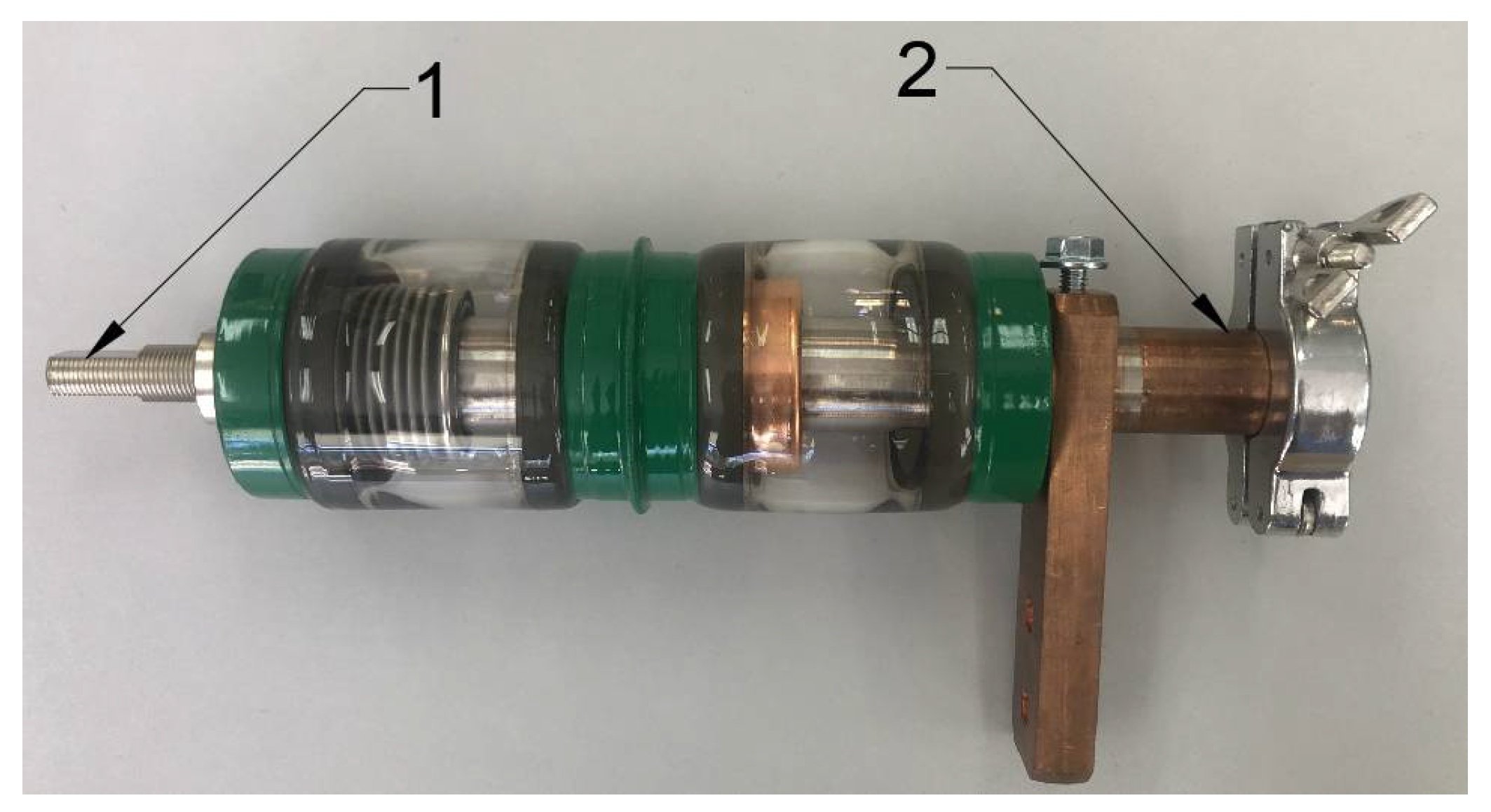
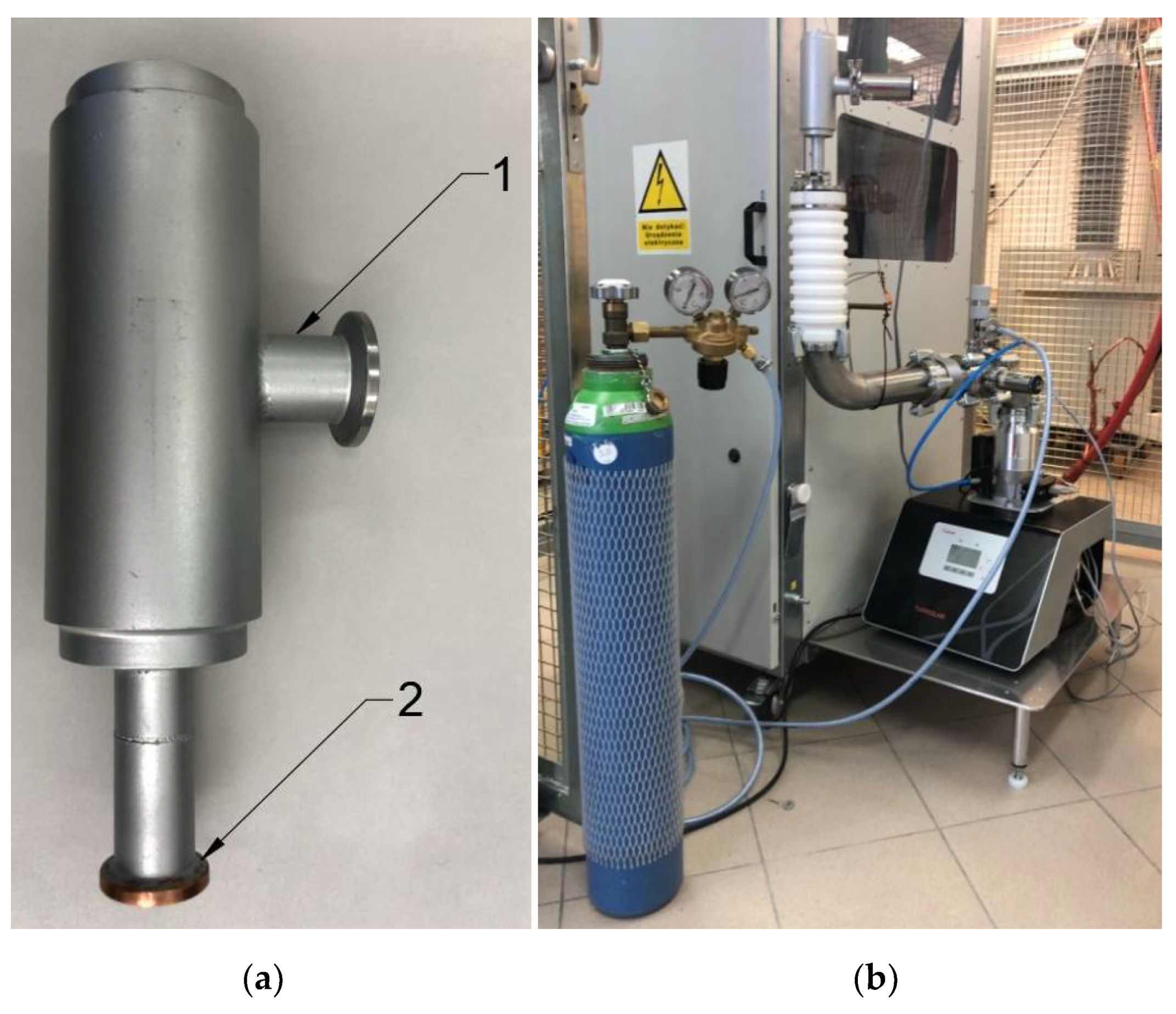
2. Research Stands, Materials and Methods

The research object in conducted research on dielectric strength was a medium-voltage vacuum interrupter of a special design intended to work in overhead switch disconnectors (Figure 1).
Vacuum interrupters of this type are used to connect current circuits in modern MV switching apparatus of closed construction. They consist mainly of two types of poles: movable and immovable, elastic bellows and a metal condensation screen. The contacts are made of WCu material, an alloy of tungsten (W) and copper (Cu) in a ratio of 70% to 30%. The characteristic technical parameters of the tested vacuum interrupter are shown in Table 3.
The first stage of work, prior to the target dielectric strength tests of the vacuum interrupter, was to determine the actual value of the pressure prevailing in the test facility during the measurements. The need for this was due to two reasons. First, due to the high voltage used in the tests, the direct connection of the measuring head to the vacuum interrupter under test could have resulted in damage to the measuring head, such as by the occurrence of an electrical breakdown in the vacuum gauge. On the other hand, measuring the pressure directly at the vacuum pump set would not be reliable due to the pressure drop across the pump channel: between the vacuum pump set and the test object. Therefore, the author’s method of determining the actual pressure value in the tested vacuum interrupter was developed.
For the application of this method, a prototype vacuum interrupter was designed and constructed, equipped with a special ferrule enabling the measuring head to be connected directly to the interrupter (at the level of its contacts), as well as a connection for connecting the pumping channel to it. The vacuum interrupter is characterized by the same geometrical dimensions as the target test object, so the pressure inside corresponds to the pressure in the vacuum interrupter used in this research. The view of the completed prototype vacuum interrupter and the complete laboratory station is shown in Figure 2.
The laboratory station consists of a set of vacuum pumps (rotary and turbomolecular), a manual dosing valve and two vacuum gauges (VG1 and VG2). The system was connected to a laboratory computer network, so that through the TPU control unit it is possible to control the pumps and to read and record measurement results in real-time. The helium used in the study is contained in a secured cylinder with a valve and a manometer. A schematic of the laboratory station is shown in Figure 3.
The idea of determining the actual value of the pressure inside the vacuum interrupter under test was to measure the pressure drop between vacuum gauge VG2, mounted at the vacuum interrupter prototype, and vacuum gauge VG1, mounted at the vacuum pump set. With the results obtained, it was possible to determine the actual pressure value inside the target interrupter tested in a later stage.
The target vacuum interrupter dielectric strength tests were performed using a dedicated, proprietary test-stand in which the test object is mounted. The stand allowed the adjustment of the electrode spacing of the vacuum interrupter, as well as the reliable and safe connection of the test system that powers the stand. The system consists mainly of a high-voltage transformer, a capacitive measuring divider and a control panel for the safe execution of the measuring processes. Ensuring the appropriate value of pressure and its regulation was done using the vacuum set described earlier. The breakdown voltages were measured in accordance with the ASTM D2477 standard. The rate of voltage rise was 2 kV/s. A schematic diagram of the laboratory test stand used for testing the dielectric strength of the vacuum interrupter is shown in Figure 4. A detailed description of the stand along with its parameters is given in publication [30].
The dielectric strength test methodology is based on making the appropriate electrical connections, setting the desired electrode spacing and pressure inside the vacuum test interrupter, configuring the test sample parameters and then running the measurement. Through a fully automated system, the voltage applied to the test object is increased until an electrical discharge occurs between the interrupter contacts. The controller records the Ud breakdown voltage value, which is used for further test analysis.

3. Results

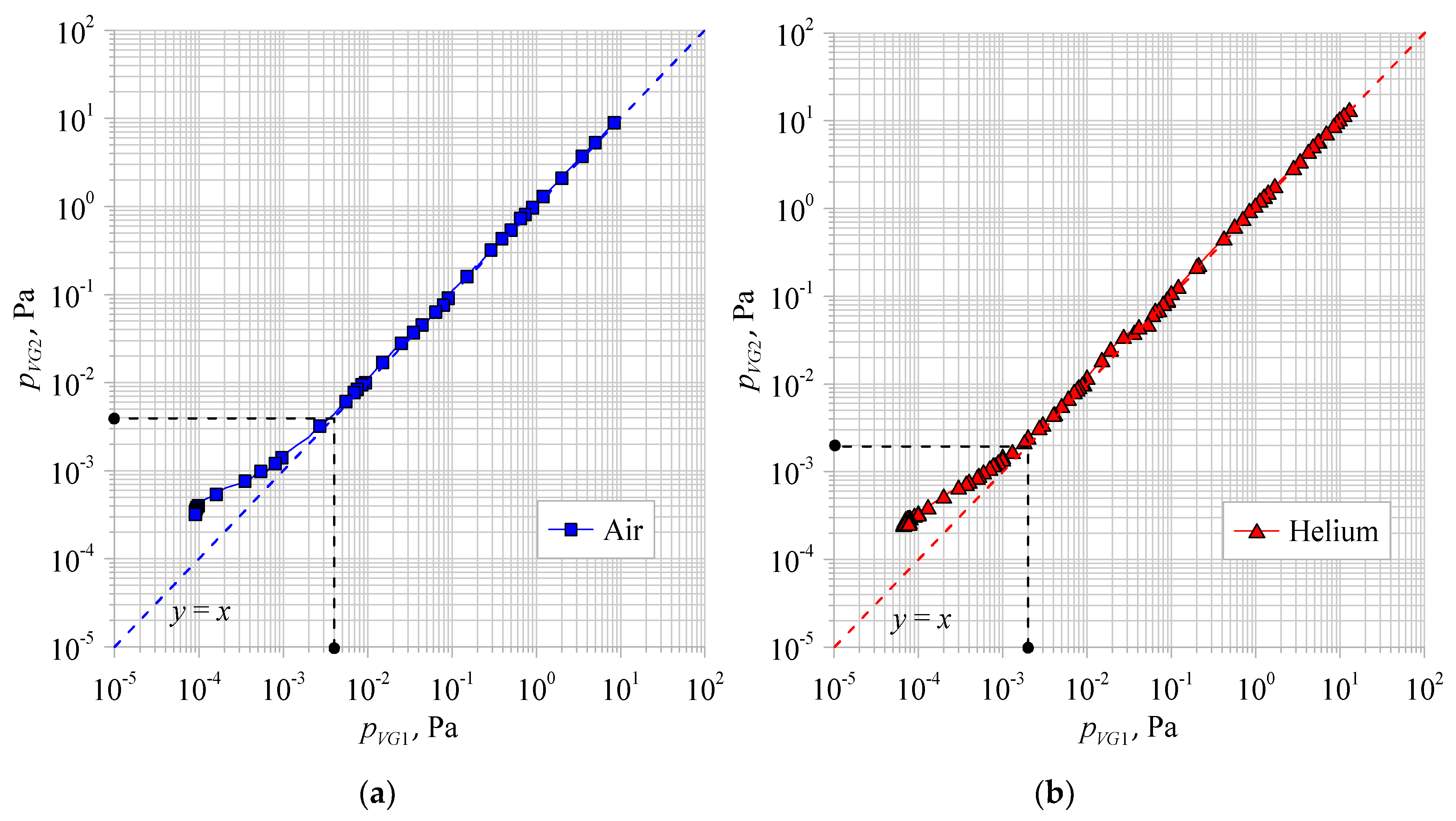
3.1. Results of Scaling the Pressure Measurement System

According to the manufacturer’s guidelines for measuring gauges, in the pressure range from 3.0 × 10⁻¹ Pa to 3.0 × 101 Pa, the actual pressure value depends linearly on the readout value. The vacuum gauges then operate in the thermal head mode (Pirani). Before analyzing the pressure measurement results obtained using vacuum gauges VG1 and VG2, it was necessary to correct the readings by an appropriate calibration factor. In the case of air, this was defined as:
C A i r = 1.00
While for helium:
C H e = 1.40
The actual value of the measured pressure was determined by the following relationships:
p e f f = C A i r × p r e a d i n g
p e f f = C H e × p r e a d i n g
Below a pressure value of 3.00 × 10⁻¹ Pa, the pressure reading is equal to the actual value, where the heads operate in ionization mode (Penning). Above a pressure value equal to 3.0 × 101 Pa, the actual pressure value should be read from the characteristics provided by the vacuum gauge manufacturer. However, these values were not subject to measurement analysis performed for the purposes of this article.
Taking into account the above relationships, pressure measurements were carried out for air and helium in the range 5.0 × 10⁻⁴ Pa–1.0 × 101 Pa, reading the values measured by vacuum gauges VG1 and VG2. From these, the characteristics pVG1 = f(pVG2) were plotted and are shown in Figure 5.
For the purpose of the correct analysis of the obtained characteristics pVG1 = f(pVG2) for air and helium, the auxiliary functions y = x were plotted on a coordinate system. Thanks to this, a certain dependence is visible, stating that above a pressure value equal to about 4.0 × 10⁻³ Pa for air and about 2.0 × 10⁻³ Pa for helium, the actual pressure value in the vacuum interrupter is equal to the readout value (pVG1 = pVG2). Below these values, the actual pressure values in the test interrupter pVG2 are greater than the pressure pVG1 measured at the vacuum pump. This phenomenon is due to the greater difficulty of maintaining a seal on the pump channel at lower pressures, for both air-based and helium-based vacuums. Any connecting element where the seal is located is a potential site for air to enter the pump channel, thereby increasing the pressure in the system. Therefore, below a pressure value of about 4.0 × 10⁻³ Pa for air and about 2.0 × 10⁻³ Pa for helium, the pressure drop between the vacuum pump set and the tested vacuum interrupter was determined:
Δ p = p V G 2 p V G 1
The obtained measurement and calculation results were used to determine the actual pressure value in the tested vacuum interrupter, in the targeted dielectric strength tests.

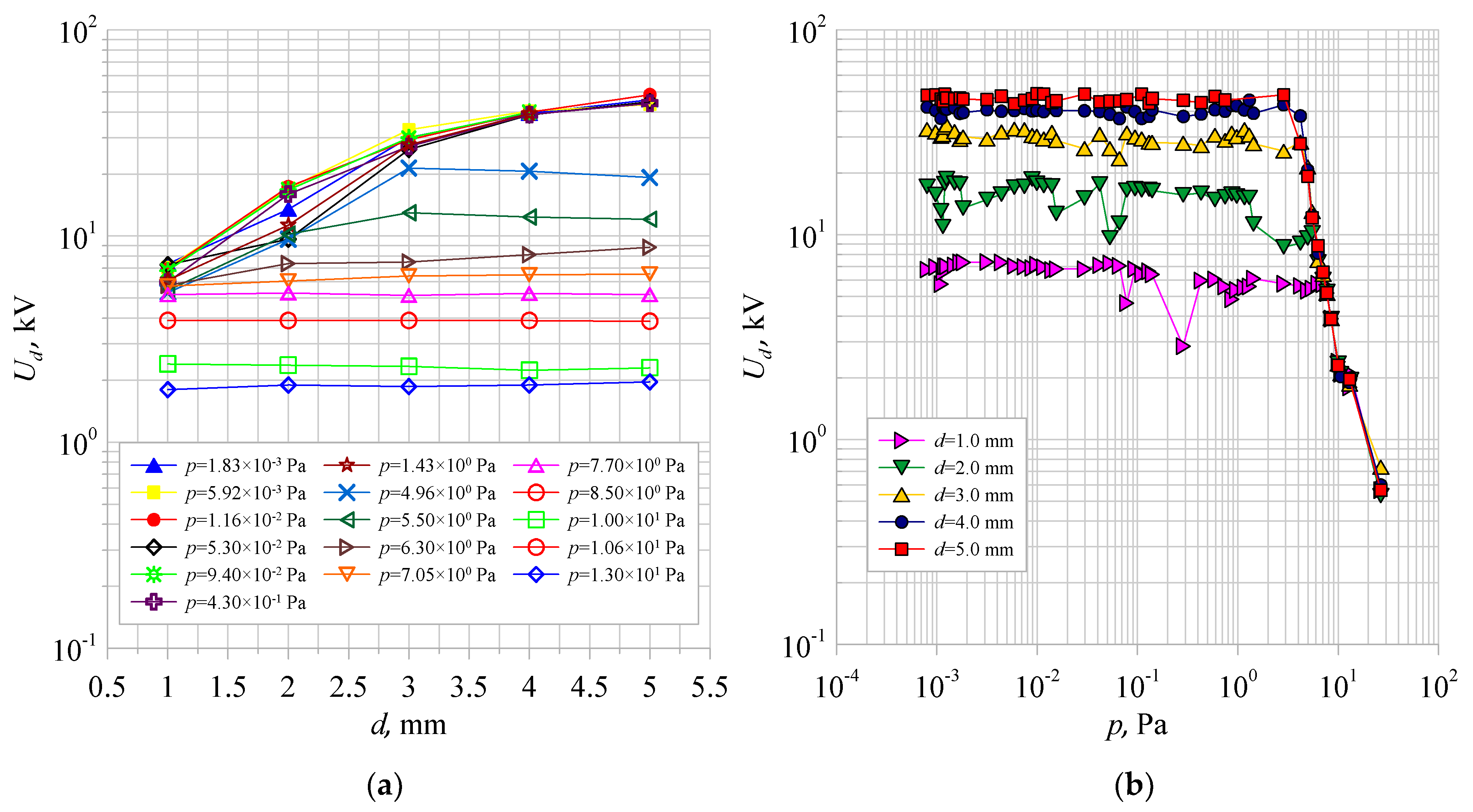
3.2. Dielectric Strength Test Results

First, the breakdown voltages of the disconnecting vacuum interrupter were measured for electrode spacing ranging from 1.0 mm to 5.0 mm and pressures ranging from 8.0 × 10⁻⁴ to 3.0 × 101 Pa by dosing air into the interrupter interior. Figure 6 shows the dependence of the measured breakdown voltages, both as a function of the electrode spacing Ud = f(d) for the selected pressure values and as a function of the pressure inside the tested vacuum interrupter Ud = f(p) for all electrode spacing settings.
From the analysis of Figure 6a, it can be seen that the higher the pressure values in-side the tested vacuum interrupter, the electrode spacing no longer affects the electrical strength of the interrupter.This situation occurred for pressures greater than 7.05 × 100 Pa. In these cases, the dielectric strength of the system depended only on the pressure inside the test object. Below a pressure value of p = 7.05 × 100 Pa, the electrical strength of the vacuum interrupter was affected by the electrode spacing in addition to the pressure inside. The larger its value, the value of the breakdown voltage was also larger, according to the relation [16]:
U d = C × d α
where: Ud—breakdown voltage, d—electrode spacing, C, α—experimentally determined constants.
By analyzing Figure 6b, two characteristic pressure ranges can be distinguished for each electrode spacing. In the first one, the dielectric strength of the vacuum interrupter remains approximately constant. These values are summarized in Table 4. It is worth noting that, as the electrode spacing decreases, the value of the pressure for which the dielectric strength of the interrupter remains constant increases. In the given pressure ranges, for the electrode spacing of 1.0 mm and 2.0 mm, a large scatter of breakdown voltages was observed.
Above the pressure values shown in Table 4, a sharp decrease in the dielectric strength of the tested vacuum interrupter was observed, which is equivalent to a loss of its insulating properties. The breakdown voltages for these parts of the characteristics are not affected by electrode spacing but only by pressure. This corresponds to the horizontal parts of the characteristics shown in Figure 6a.
Analogous measurements were performed for the same vacuum interrupter by increasing the pressure inside by dosing helium into it. Figure 7a shows the relations Ud = f(d) for selected values of pressure, while Figure 7b shows the relation Ud = f(p) for the electrode spacing from 1.0 to 5.0 mm.
It can be observed in Figure 7a that, for pressures above a value equal to p = 4.0 × 101 Pa, it is apparent that electrode spacing has no significant effect on the value of the breakdown voltages. Below this pressure, as electrode spacing increases, the value of the breakdown voltage increases.
In Figure 7b, analogous intervals of Ud = f(p) characteristics can be distinguished for each tested electrode spacing d. In the interval in which the dielectric strength of the system remains constant, a smaller scatter of the measured values of Ud voltages was observed compared to the vacuum interrupter to which air was dosed. These values, along with the pressure ranges, are summarized in Table 5. Analogously to the case where air was dosed into the vacuum interrupter, there was a sharp drop in the dielectric strength of the system above the pressure values specified in the table below.
It is crucial from the point of view of the electrical strength of the vacuum interrupter to compare the measured values of the breakdown voltages Ud for different types of residual gases, i.e., air and helium. The characteristics of the Ud breakdown voltages as a function of pressure (air and helium) p for two electrode spacing were selected: 3.0 mm and 5.0 mm. The results are shown in Figure 8a,b.
For an electrode spacing of 3.0 mm, the maximum Ud voltages for both air and helium reach approximately the same values, equal to about 30.0 kV. What is important in this case is the moment when the insulating properties of the interrupter are lost. When air is dispensed into it, the dielectric strength drops rapidly after a value equal to p = 4.20 × 100 Pa. For an interrupter wherein the residual gases consist of helium, a constant value of dielectric strength is maintained up to a pressure level equal to p = 2.67 × 101 Pa. Only above this value is there a sharp drop in the measured breakdown voltages.
For an electrode spacing of 5.0 mm, an analogous situation occurred. The constant value of the electric strength of the vacuum interrupter, to which air was dosed, was maintained up to a pressure value of p = 3.0 × 100 Pa and amounted to about 46.0 kV. For the helium-filled interrupter, the constant electrical strength value reached a similar value, but was maintained up to a pressure value equal to p = 1.37 × 101 Pa.
In order to illustrate the better insulating properties of the helium-filled vacuum interrupter at higher interior pressures compared to the air-filled interrupter, the characteristics in the electrode spacing range of 1.0 mm to 5.0 mm were compared. A reference value of pressure inside the interrupter, equal to pref = 2.0 × 101 Pa, was chosen and the Ud breaking voltages for the two types of residual gas were compared. While the insulating properties of the air-filled vacuum interrupter were lost for each of the electrode spacing tested at the reference pressure, they were still maintained at a safe level for the helium-filled interrupter. The measured values are summarized in Table 6.

4. Conclusions

On the basis of the conducted tests of the dielectric strength of vacuum interrupters filled with two types of gases: air and helium, it was found that the interrupter filled with helium maintains full switching capability in a larger pressure range. These results are promising due to the possibility of increasing the operating pressure of the vacuum interrupter. The rated operating pressure of currently manufactured vacuum interrupters is approximately 1.0 × 10⁻³ Pa, so the insulating medium proposed by the authors of this article makes it possible to increase the pressure inside the interrupter many times. As a result, it will be easier to maintain the tightness of vacuum interrupters used in switching devices, and the values of switching overvoltages occurring in power systems will be reduced. Moreover, the complete elimination of harmful greenhouse gases, such as SF6, is in line with the current climate policy of the European Union.
Measurements of the electrical strength of the vacuum interrupters were made for electrode spacing in the range of 1.0 to 5.0 mm, even though the electrode spacing in the interrupters operating in the currently used vacuum switching apparatus is about 9.0 mm. This distance was not measured, however, due to the limitation of the voltage capabilities of the test system to 50 kV.
Further research plans by the authors of this paper concern the use of other insulating gases and their mixtures to improve the performance of vacuum interrupters, focusing on both dielectric strength and arc processes. Furthermore, the research will cover an increased range of electrode spacing due to the acquisition of a voltage set with a rated test voltage of 110 kV.

Author Contributions

P.W. proposed to study the influence of helium on the dielectric strength of medium-voltage vacuum interrupters and guided the work. M.L. and D.K. did the calculations and wrote the paper. P.W. and C.K. revised the results and contributed to the discussions. All authors have read and agreed to the published version of the manuscript.

Funding

This research was founded by Lublin University of Technology, grant number FD-20/EE-2/704.

Institutional Review Board Statement

Not applicable.

Informed Consent Statement

Not applicable.

Data Availability Statement

Not applicable.

Acknowledgments

This work was supported by The National Centre for Research and Development and co-financed from the European Union funds under the Smart Growth Operational Programme (grant # POIR.04.01.04-00-0130/16).

Conflicts of Interest

The authors declare no conflict of interest.

References

  1. Polish Power Transmission and Distribution Association (PTPiREE)—Report 2019. 2020. Available online: http://www.ptpiree.pl/raporty/2020/raport_ptpiree_druk.pdf (accessed on 10 May 2021).
  2. Konarski, M.; Węgierek, P. The use of power restoration systems for automation of medium voltage distribution grid. Przegląd Elektrotechniczny 2018, 94, 167–172. [Google Scholar] [CrossRef] [Green Version]
  3. Pan, B.; Wang, G.; Shi, H.; Shen, J.; Ji, H.-K.; Kil, G.-S. Green gas for grid as an eco-friendly alternative insulation gas to SF6: A Review. Appl. Sci. 2020, 10, 2526. [Google Scholar] [CrossRef] [Green Version]
  4. Xiao, S.; Zhang, X.; Tang, J.; Liu, S. A review on SF6 substitute gases and research status of CF3I gases. Energy Rep. 2018, 4, 486–496. [Google Scholar] [CrossRef]
  5. Park, H.; Lim, D.-Y.; Bae, S. Partial discharge and surface flashover characteristics with O2content in N2/O2 mixed gas under a non-uniform field. IEEE Trans. Dielectr. Electr. Insul. 2018, 25, 1403–1412. [Google Scholar] [CrossRef]
  6. Beroual, A.; Haddad, M.A. Recent advances in the quest for a new insulation gas with a low impact on the environment to replace sulfur hexafluoride (SF6) gas in high-voltage power network applications. Energies 2017, 10, 1216. [Google Scholar] [CrossRef] [Green Version]
  7. Breidenich, C.; Magraw, D.; Rowley, A.; Rubin, J. Kyoto Protocol to the UN Framework Convention on Climate Change. Am. J. Int. Law 1998, 92, 315–331. [Google Scholar] [CrossRef]
  8. Dunse, B.L.; Fraser, P.J.; Krummel, P.B.; Steele, L.P.; Derek, N. Australian HFC, PFC, Sulfur Hexafluoride and Sulfuryl Fluoride Emissions. CSIRO Ocean. Atmos. 2015, 1–37. [Google Scholar] [CrossRef]
  9. Mota-Babiloni, A.; Navarro-Esbrí, J.; Barragán-Cervera, Á.; Molés, F.; Peris, B. Analysis based on EU Regulation No 517/2014 of new HFC/HFO mixtures as alternatives of high GWP refrigerants in refrigeration and HVAC systems. Int. J. Refrig. 2015, 52, 21–31. [Google Scholar] [CrossRef]
  10. Florkowski, M.; Furgał, J.; Kuniewski, M.; Pająk, P. Overvoltage impact on internal insulation systems of transformers in electrical networks with vacuum circuit breakers. Energies 2020, 13, 6380. [Google Scholar] [CrossRef]
  11. Lech, M.; Kostyła, D. Method for determining the actual pressure value in a MV vacuum interrupter. Inform. Autom. Pomiary Gospod. Ochr. Sr. IAPGOS 2021, 1, 28–31. [Google Scholar] [CrossRef]
  12. Kiszło, S.; Partyka, J. The ways to improve the parameters of vacuum chambers used in the new construction of medium voltage disconnectors. Przegląd Elektrotechniczny 2015, 91, 288–291. [Google Scholar] [CrossRef]
  13. Janiszewski, J.; Batura, R. Wytrzymałość elektryczna przerwy międzystykowej wyłącznika próżniowego. Przegląd Elektrotechniczny 2010, 86, 178–181. [Google Scholar]
  14. Kiszło, S. Rozłączniki wysokonapięciowe do 24 kV—Analiza konstrukcji i parametrów technicznych w świetle aktów normatywnych, prowadzonych prób i badań. Wiadomości Elektrotechniczne 2014, 5, 46–48. [Google Scholar] [CrossRef]
  15. Hunter, S.R.; Carter, J.G.; Christophorou, L.G. Electron motion in the gases CF4, C2F6, C3F8, and n-C4F10. Phys. Rev. A 1988, 38, 58–69. [Google Scholar] [CrossRef]
  16. Opydo, W. Właściwości Gazowych i Próżniowych Wysokonapięciowych Układów Izolacyjnych; Politechnika Poznańska: Poznań, Poland, 2008; pp. 1–136. ISBN 978-83-7143-348-1. [Google Scholar]
  17. Huk, M.P.; Igo-Kemens, P.; Wagner, A. Electron attachment to oxygen, water, and methanol, in various drift chamber gas mixtures. Nucl. Instr. Meth. Phys. Res. A 1988, 267, 107–119. [Google Scholar] [CrossRef]
  18. Kuroiwa, H.; Nitoh, O.; Fujii, K.; Khalatyan, N. The influence of oxygen contamination on the performance of a mini-jet-cell-type drift chamber for the JLC-CDC. Nucl. Instr. Meth. Phys. Res. A 2004, 516, 377–389. [Google Scholar] [CrossRef]
  19. Juhre, K.; Kynast, E. N2 and N2/CO2 Mixture in Gas Insulated Compartments under High Pressure. Gaseous Dielectrics X 2004, 211–216. [Google Scholar] [CrossRef]
  20. Chen, L.; Widger, P.; Tateyama, C.; Kumada, A.; Griffiths, H.; Hidaka, K.; Haddad, A. Breakdown Characteristics of CF3I/CO2 gas mixtures under fast impulse in rod-plane and GIS geometries. In Proceedings of the 19th International Symposium of High Voltage Engineering (ISH), Pilsen, Czech Republic, 23–25 August 2015. [Google Scholar]
  21. Christophorou, L.G.; Olthoff, J.K.; Green, D.S. Gases for Electrical Insulation and Arc Interruption: Possible Present and Future Alternatives to Pure SF6; National Institute of Standards and Technology: Gaithesburg, MD, USA, 1997; pp. 1–56. [Google Scholar] [CrossRef]
  22. Cigre Publication: Guide for SF6 Gas Mixtures, August 2000. Available online: https://e-cigre.org/publication/ELT_191_10-cigre-guide-for-sf6-gas-mixtures (accessed on 15 May 2021).
  23. Lee, W.; Jun, J.; Oh, H.; Park, J.; Oh, Y.; Song, K.; Jang, H. Comparison of the interrupting capability of gas circuit breaker according to SF6, g3,and CO2/O2 mixture. Energies 2020, 13, 6388. [Google Scholar] [CrossRef]
  24. Ciok, Z. Ochrona Środowiska w Elektroenergetyce; PWN: Warsaw, Poland, 2001; pp. 1–480. ISBN 9788301186005. [Google Scholar]
  25. Graber, L.; Kim, W.J.; Cheetham, P.; Kim, C.H.; Rodrigo, H.; Pamidi, S.V. Dielectric properties of cryogenic gas mixtures containing helium, neon, and hydrogen. IOP Conf. Ser. Mater. Sci. Eng. 2015, 102, 012018. [Google Scholar] [CrossRef] [Green Version]
  26. Park, C.; Pamidi, S.; Graber, L. The dielectric strength of dissociated cryogenic gas media. J. Appl. Phys. 2018, 124, 104104. [Google Scholar] [CrossRef]
  27. Ramakers, M.; Michielsen, I.; Aerts, R.; Meynen, V.; Bogaerts, A. Effect of argon or helium on the CO2 conversion in a dielectric barrier discharge. Plasma Process. Polym. 2015, 12, 755–763. [Google Scholar] [CrossRef]
  28. Park, H.; Lim, D.; Bae, S. Surface discharge mechanism on epoxy resin in electronegative gases and its application. Appl. Sci. 2020, 10, 6673. [Google Scholar] [CrossRef]
  29. Belevtsev, A.A. Charge kinetics in weakly ionized plasma of electronegative gases. High Temp. 2013, 51, 435–442. [Google Scholar] [CrossRef]
  30. Węgierek, P.; Lech, M.; Kozak, C.; Pastuszak, J. Methodology for testing the electrical strength of vacuum chambers designed for modern medium voltage switchgear. Metrol. Meas. Syst. 2020, 27, 687–700. [Google Scholar] [CrossRef]
Figure 1. Research object—MV vacuum interrupter of special design: 1—movable contact adapted to mounting the interrupter in a laboratory stand, 2—fixed contact with connection for pumping channel.
Energies 14 03742 g001
Figure 2. Test stand: (a) prototype of a vacuum interrupter designed to determine the actual pressure value in test objects (1—vacuum gauge connection, 2—pump channel connection), (b) view of the complete test stand.
Energies 14 03742 g002
Figure 3. Schematic of the stand designed to determine the actual pressure value in the tested vacuum interrupters (1—prototype vacuum interrupter, 2—vacuum gauge VG2, 3—manual dosing valve, 4—vacuum gauge VG1, 5—turbomolecular pump, 6—rotary pre-pump, 7—gases dosed to the inside of the tested object).
Energies 14 03742 g003
Figure 4. Scheme of test system for testing dielectric strength of MV vacuum interrupters (1—control panel, 2—power transformer, 3—capacitance divider, 4—vacuum interrupter under test, 5—manual dosing valve, 6—vacuum gauge, 7—turbomolecular pump, 8—rotary pre-pump, 9—system controller, 10—technical gases dosed to the inside of the tested object).
Energies 14 03742 g004
Figure 5. Dependence of the pressure measured by vacuum gauge VG1 on the pressure measured by vacuum gauge VG2 taking into account correction factors for (a) air and (b) helium.
Energies 14 03742 g005
Figure 6. The dependence of the breakdown voltages Ud as a function of (a) the electrode spacing d for selected pressures and (b) the pressure p inside the test vacuum interrupter, for residual gases that are pure air.
Energies 14 03742 g006
Figure 7. Dependences of breakdown voltages Ud as a function of (a) electrode spacing d for selected pressure values and (b) pressure p inside the tested vacuum interrupter, for residual gases being helium.
Energies 14 03742 g007
Figure 8. Comparison of the dielectric strength of a vacuum interrupter filled with air and helium for two electrode spacing: (a) 3.0 mm, (b) 5.0 mm.
Energies 14 03742 g008
Table 1. Selected chemicals and their GWP100.
SubstanceGWP100
Carbon dioxide CO21
Methane CH423
Nitrous oxide N2O296
Carbon tetrafluoride CF45700
Freon R-12 (CFC-12)10,600
Sulfur hexafluoride SF622,200
Table 2. Predicted directions of research for gas mixtures used in power engineering [23,24].
SpecificationApplication in InsulationApplication for Electric Arc Extinguishing
Gases used today
and mixtures thereof
40% SF6 + 60% N2
50% SF6 + 50% N2
40% SF6 + 60% N2
50% SF6 + 50% N2
Directions for current ongoing researchpure nitrogen (N2) under high pressure, low concentration of SF6 and pure nitrogenSF6 + He
Forecasted research directionsCO2
SO2
N2O
N2+SO2
N2+c-C4F8
SO2+SF6
SO2+c-
C4F8SF6+CO2
SF6+Ar
SF6+CF4
SF6+C2F6
SF6+N2+He
SF6+N2+ArHe+electronegative gases
Table 3. Technical parameters of MV vacuum interrupter used in this study.
Type of ParameterParameter Value
Rated frequency50 Hz
Rated voltage24 kV
Rated impulse withstand voltage125 kV
Rated continuous current400 A
Rated 1s withstand current16 kA
Rated peak withstand current40 kA
Rated short-circuit making current16 kA
Breaking current in circuit with low inductance400 A
Mechanical durability2000 cycles
Table 4. The measured values of the breakdown voltages Ud in the compartment with constant dielectric strength for a vacuum interrupter with residual gases being pure air.
Electrode SpacingBreakdown VoltagePressure Range
d, mmUd, kVp, Pa
1.07.008.00 × 10−4–7.70 × 100
2.017.008.00 × 10−4–5.50 × 100
3.031.008.00 × 10−4–4.20 × 100
4.040.008.00 × 10−4–4.00 × 100
5.047.008.00 × 10−4–3.00 × 100
Table 5. Measured values of breakdown voltages Ud in a compartment with constant dielectric strength for a vacuum interrupter with residual gases being helium.
Electrode SpacingBreakdown VoltagePressure Range
d, mmUd, kVp, Pa
1.05.008.00 × 10−4–5.33 × 101
2.013.008.00 × 10−4–2.67 × 101
3.029.008.00 × 10−4–2.67 × 101
4.036.008.00 × 10−4–2.67 × 101
5.046.008.00 × 10−4–1.37 × 101
Table 6. Comparison of the breakdown voltages Ud of vacuum interrupters filled with air and helium, for electrode spacing from 1.0 to 5.0 mm and reference pressure equal to pref = 2.00 × 101 Pa.
Electrode Spacing
d, mm
Breakdown Voltage Ud, kV
Residual Gas Type
AirHelium
pref = 2.0 × 101 Pa
1.0Ud(Air) = 1.20Ud(He) = 3.50
2.0Ud(Air) = 0.90Ud(He) = 8.00
3.0Ud(Air) = 1.10Ud(He) = 27.00
4.0Ud(Air) = 1.00Ud(He) = 31.00
5.0Ud(Air) = 1.00Ud(He) = 40.00
Publisher’s Note: MDPI stays neutral with regard to jurisdictional claims in published maps and institutional affiliations.

