Article

Failure Mechanism Analysis and Support Technology for Roadway Tunnel in Fault Fracture Zone: A Case Study

1
School of Civil Engineering and Architecture, Henan University, Kaifeng 475000, China
2
State Key Laboratory for Geomechanics and Deep Underground Engineering, China University of Mining and Technology, Xuzhou 221116, China
*
Author to whom correspondence should be addressed.
Energies 2021, 14(13), 3767; https://doi.org/10.3390/en14133767
Submission received: 3 March 2021 / Revised: 20 May 2021 / Accepted: 24 May 2021 / Published: 23 June 2021

Abstract

:
This paper introduces a case study on the failure mechanism and support design of a roadway tunnel in the fault fracture zone of the 106 mining area in the Yuandian no.2 coal mine. Based on the on-site geological conditions (in-situ stress test, borehole television imaging, and lithological analysis), the failure mechanism of the roadway tunnel in the fault fracture zone was studied. The test results showed that the high tectonic stress, fractured rock, and poor lithology are the primary reasons for the roadway instability. According to the support principles of grouting reinforcement, pre-reinforced support, and rational support range, a new type of combined support technology was proposed, including advanced grouting, grouting bolts, and grouting anchor cables. A 100 m roadway section was selected for field testing using the new support scheme, and detailed deformation monitoring was performed. Monitoring results showed that the roadway deformation under the new support was significantly reduced. During the roadway excavation process, no roof collapse phenomenon occurred, and the safety of roadway excavation was ensured. This successful case provides an important reference for similar roadway projects in the fault fracture zone.

1. Introduction

The stability of roadway surrounding rock has always been a key issue in underground engineering [1,2,3,4,5]. During the roadway excavation process, many geologically unfavourable conditions can be encountered, including fault fracture zones [6,7]. Commonly used excavation methods mainly include the mining method, new Austrian method, excavation machine, and shield method. Due to working environment and support cost constraints, the new Austrian method is commonly used in underground excavation. That is, the theory of rock mass mechanics is applied, based on the self-supporting capacity of surrounding rock, and supporting methods such as bolts and shotcrete are used to support and control surrounding rock deformation. When the roadway passes through the fault fracture zone, geological issues such as water inrush and roof collapse may occur due to the low strength and poor stability of the rock mass [8,9]. During the use of the roadway, large deformation of surrounding rocks may occur, causing the instability and damage of the supporting structure. In order to ensure the stability of the roadway surrounding rock in the fault fracture zone, it is necessary to study its failure mechanism, and then propose a reasonable support design [10,11,12].
Recently, numerous studies have been performed on the failure mechanisms of roadway tunnel in the fault fracture zone [13,14,15]. Piotr et al. [16] analysed the influence of small throw fault on the convergence of the roadway and the degree of cracking around the roadway. Wang et al. [17] established a three-dimensional numerical model of a tunnel through a fault fracture zone, and results showed that the fault fracture zone reduced surrounding rock stability. Qian et al. [18] and Qian et al. [19] analysed the failure characteristics and influencing factors of the large deformation in tunnel surrounding rock with a depth of 800 m. Das et al. [20] studied the influence of different fault dip and friction angles on the stability of underground coal mines. However, most of these studies are based on theoretical studies, and do not combine the specific geological conditions on-site. Due to the complex and changeable engineering geological conditions, the roadways in the fault fracture zone have different failure mechanisms. The complicated geotechnical environment and mechanical properties of surrounding rocks are the main reasons for roadway failure [21,22,23].
The research on the failure mechanism of the roadway is to ensure the rationality of the support design. Many support technologies have been proposed by experts and scholars. Wang, Zhang, Wei, Zhang, and Guo [13] proposed the whole-section anchor-grouting reinforcement technology. Qian et al. [24] proposed and implemented ground surface pre-grouting reinforcement technology. Liu et al. [25] proposed the combination support technology of “Bolt-mesh-spurting + prestressed hollow grouting anchor”. According to the summary, there are generally the following types of support technology for roadways in the fault fracture zone: (1) U-steel support combined with bolts and cables [26,27]. This technology is only suitable for roadways passing through a small fault fracture zone with simple geological conditions. (2) U-steel support combined with grouting bolts and grouting anchor cables [28]. This technology is the most commonly used support technology of roadway in the fault fracture zone, but it is not suitable for the fault fracture zone with poor geological conditions. (3) Ground surface pre-grouting reinforcement technology [24]. This technology is suitable for the fault fracture zone with poor geological conditions. However, the high support costs and high construction technology requirements are its determination. In order to prevent roof collapse accidents, advanced grouting technology is necessary [29,30]. Aiming at the fault fracture zone with poor geological conditions, a new roadway support technology should be proposed.
This contribution examines the 106 mining area of the Yuandian no.2 coal mine to study the instability mechanism and support design of an underground roadway through a fractured fault zone in tectonically deformed sedimentary rock. Considering the roof collapse soon after roadway excavation, a new type of combined support technology, including advance grouting, grouting bolts, and grouting anchor cables, was proposed based on the roadway failure mechanism. With the new support scheme, the safety hazard of roof collapse after roadway excavation can be effectively solved, and the long-term stability of roadway was ensured. The results provide a reference for the support design of roadway engineering in similar geologic conditions.

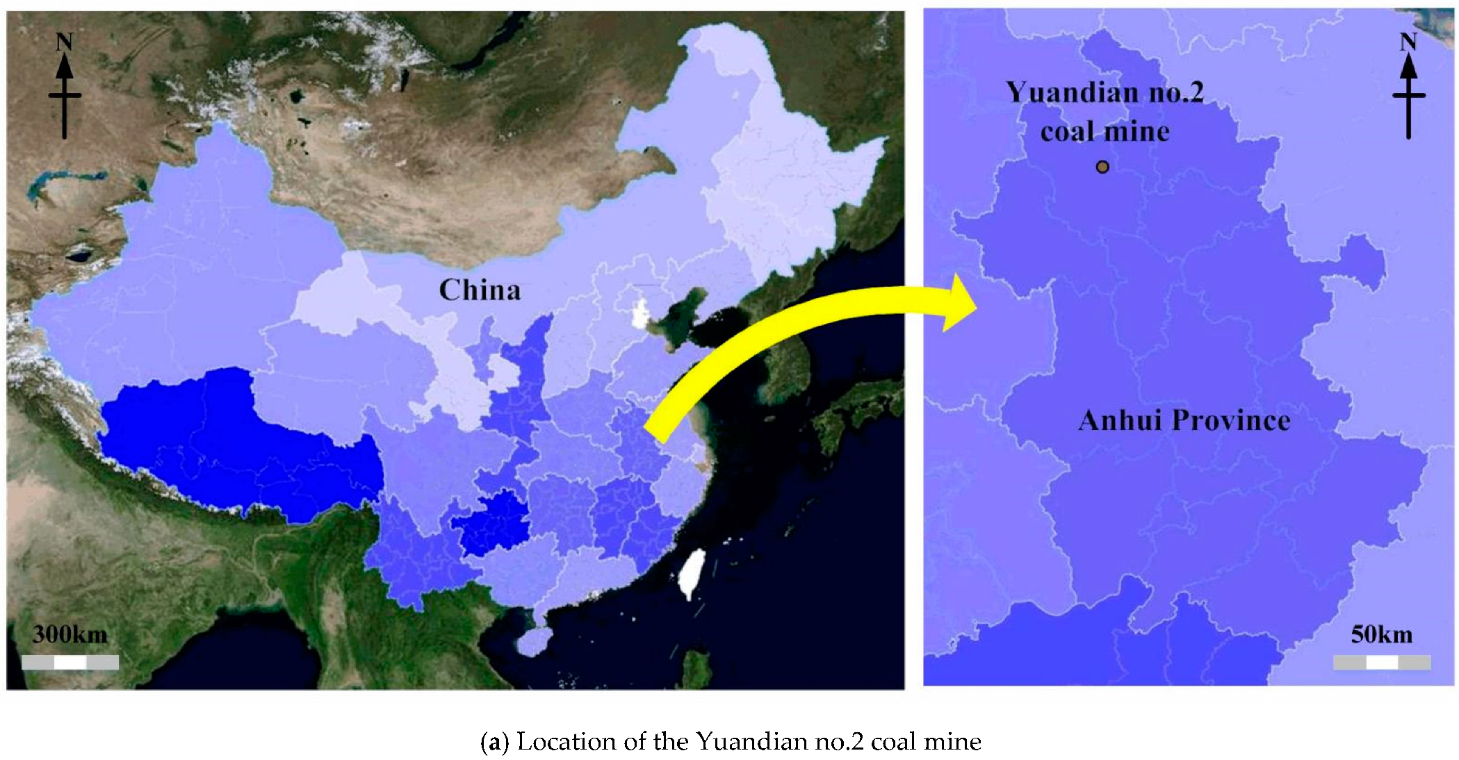
2. Geologic and Engineering Backgrounds

The 106 mining area of the Yuandian no.2 coal mine is located in the north-eastern part of the mine field, with an east–west width of 1900~2700 m, a north–south length of 1800~2500 m, and an area of 4.74 km2. The 106 mining area has a NE-trending uniclinal structure with a NW-dip. The dip angle of the formation varies from 4° to 33° and is generally between 7° and 26°. The two layers containing the coal seam are the 10-coal and 11-coal layers. In the area, 115 faults were detected, all of which were NW-trending normal faults. There are 5 faults with an offset of more than 100 m, 5 faults with an offset of 40~100 m, 32 faults with an offset of 10~40 m, 18 faults with an offset of 5~10 m, and 55 faults with an offset of 0~5 m. LWF54 is the main fault experienced by the test roadway in the manuscript.
The north auxiliary blind inclined shaft, north transportation blind inclined shaft, and north air return blind inclined shaft compose the primary roadway in the 106 mining area (Figure 1). The trend of the roadway is N47°, and the horizontal spacing between the individual roadways is 35 m. The height of the roadway floor is between −553.3 and −710 m, and the construction level is about 20 m above the 10-coal roof. The 106 dark mining well in the 106 mining area runs from the 10-coal roof sandstone layer to 51-coal, mainly exposing aluminium mudstone, 82-coal, 81-coal, 72-coal, and the interlayer sandstone and mudstone. A comprehensive stratigraphic column of the mining area is shown in Figure 2. The lithology of the fault fracture zone is mixed, mainly mudstone, siltstone, and a small amount of sandstone, with local carbonaceous mudstone or coal. Unit water inflow and permeability coefficient of rock mass were obtained through the pumping test: q = 0.0035 L/s.m, K = 0.0298 m/day, and the results showed that the water richness was weak.
The cross-section of the blind inclined shaft in the 106 mining area is a semi-circular arch with straight walls (Figure 3). The height of the straight wall and semi-circular arch is 1.5 and 2.5 m respectively, whereas the width of the roadway is 5 m. The initial roadway support structure was composed of anchor mesh and cable combined with a shotcrete support. The anchors have a diameter of 22 mm and a length of 2.6 m. The distance between the anchors along the roadway axis and the radial direction are both 0.8 m. The anchor cable has a diameter of 17.8 mm and a length of 6.2 m, and is composed of 8 prestressed steel wires with a diameter of 7 mm. The distance between the anchors along the roadway axis and the radial direction is 2.0 and 2.4 m. The thickness of sprayed concrete (C20) is 100 mm (Figure 3).
With this roadway support structure adopted, the anchor cable and bolt support were destroyed. As shown in Figure 4, the roof fracture and floor heave were clearly observed during the excavation process. Figure 5 shows the displacement curve of deep surrounding rock in the roof at different tested depths. At some zones, the displacement of deep surrounding rock in the roof was extremely large, and the maximum value reaches 128 mm. The damage of the roadway surrounding rock may be caused by the weak and broken nature of the fault fracture zone, which contains disordered layering, and numerous fractures. As time passed, the anchor cables were loose, which caused the anchor cable support to fail [31]. Moreover, the stress on the fault fracture zone was complicated, which allowed for easy deformation of the roadway after excavation, and thus seriously endangered roadway safety. The field monitoring results showed that the initial support design cannot meet the roadway support requirements in the fault fracture zone.

3. Failure Mechanism Analyses

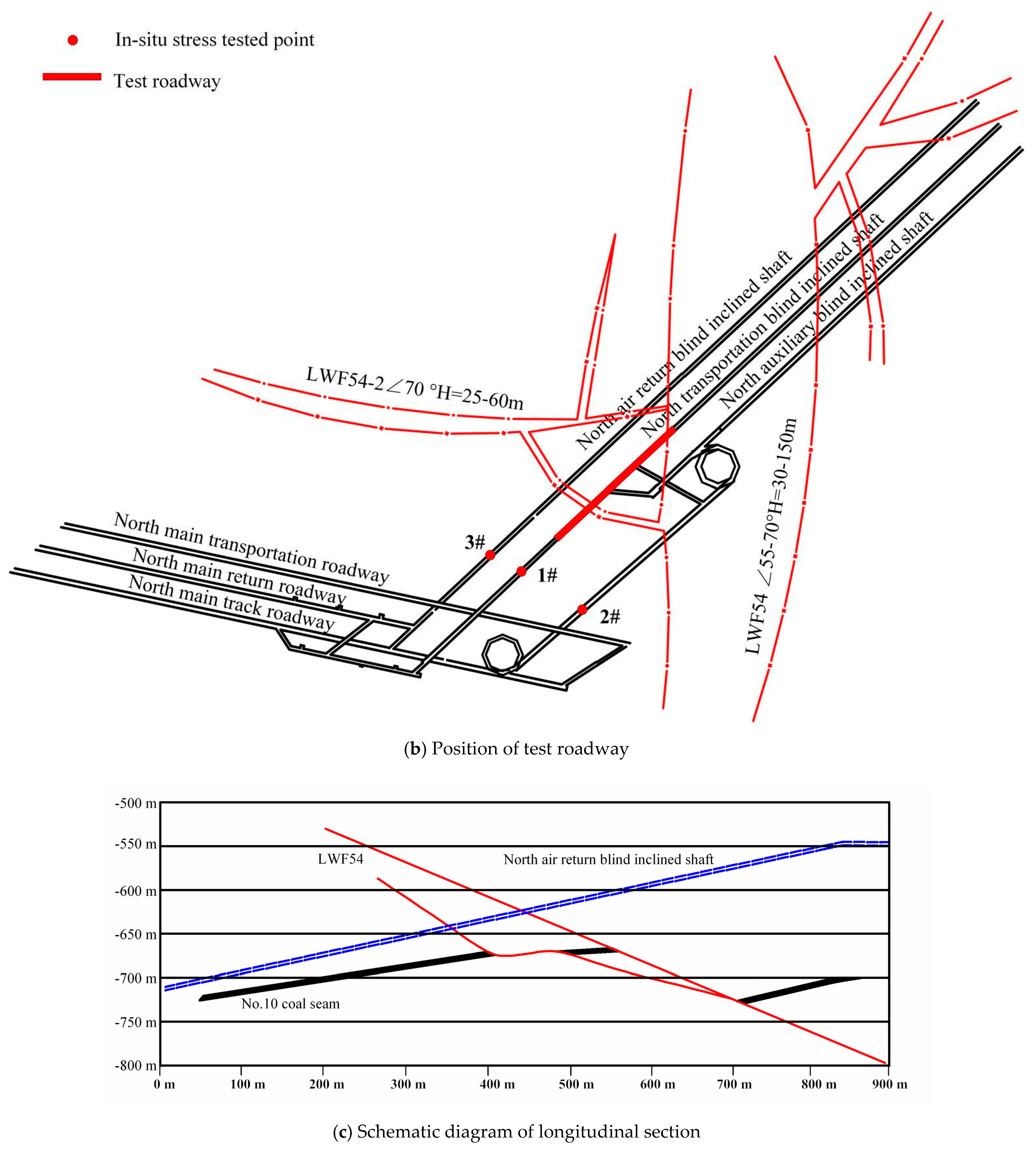
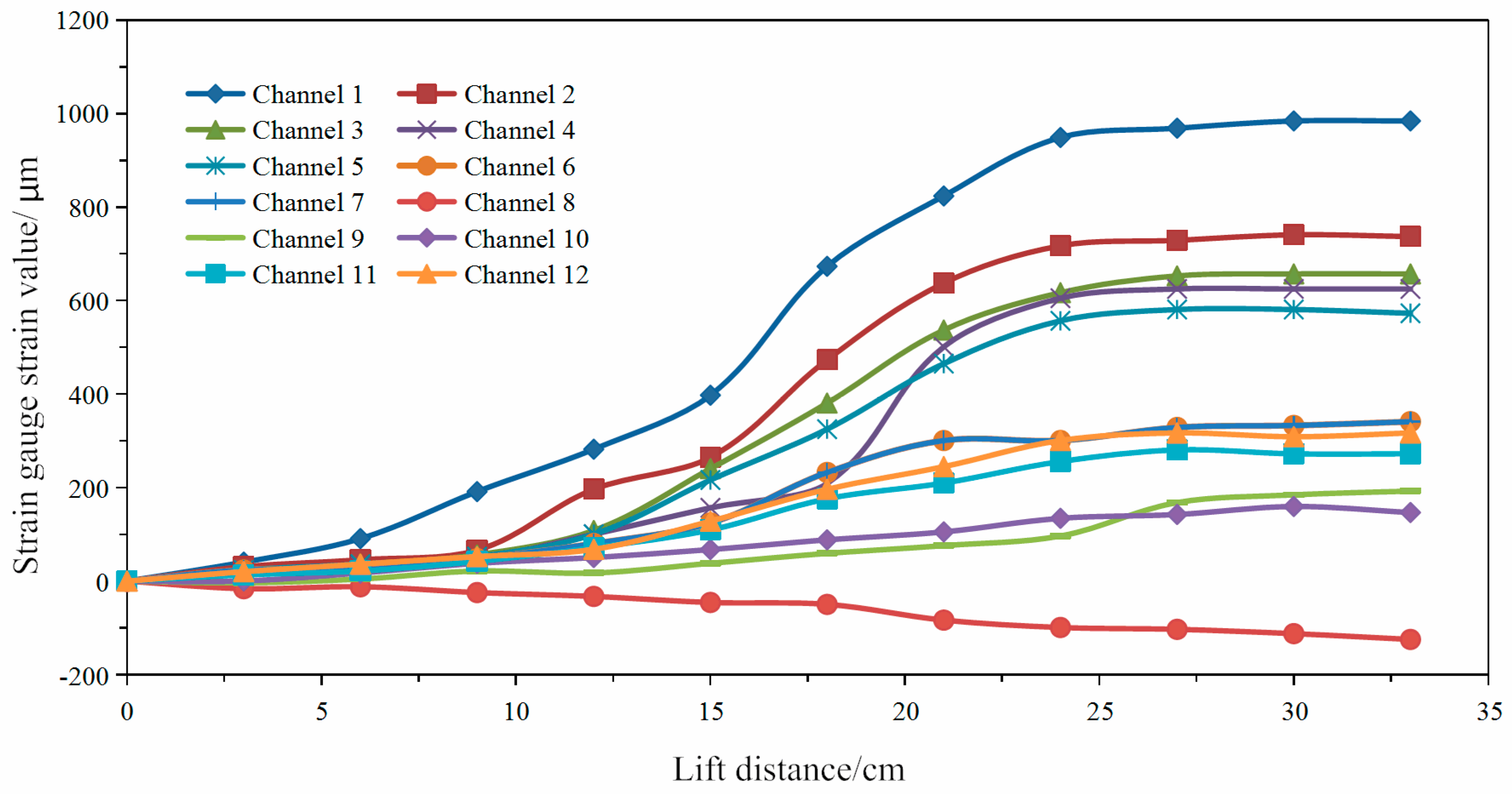
3.1. In-Situ Stress Test

The geological structure in the fault fracture zone is complex, resulting in a complicated distribution of in-situ stress. Determining the in-situ stress in the fault fracture zone is important for stability control of the roadway surrounding rock [32,33,34].
According to the actual engineering geological conditions in the 106 mining area, three tested points were selected for the in-situ stress test. DYL-16 hollow inclusion triaxial ground strain gauges were adopted to measure in-situ stress using the stress-relieving method. The drilling location and technical characteristics of the in-situ stress tested point in the mining area are shown in Figure 1 and Table 1, respectively.
Figure 6 shows the typical stress relief curves at tested point 1. The stress relief curve shows good regularity, indicating that the working state of the strain gauge at the measuring point is normal. When the release distance does not reach the location of the strain gauge, the strain value is small, when the release distance is close to the location of the strain gauge, the strain value changes greatly, and when the release distance exceeds the location of the strain gauge, the strain value gradually stabilises. After the in-situ stress was measured, rock samples were collected, and the elastic modulus and Poisson’s ratio of the rock samples were measured (Table 2). By processing the measured data, the magnitude and direction of the in-situ stress components and principal stress of the tested point were calculated, which are summarised in Table 3.
The maximum principal stress at the No. 1 in-situ stress-tested point (burial depth 511 m) is 20.04 MPa, with an azimuth angle of 81.36°, whereas the minimum principal stress is 10.31 MPa with an azimuth angle of 278.32°, and the lateral pressure coefficient is 1.56. The maximum principal stress at the No. 2 in-situ stress-tested point (burial depth 553 m) is 20.25 MPa, with an azimuth angle of 88.25°, while the minimum principal stress is 11.00 MPa with an azimuth angle of 276.66°, and the lateral pressure coefficient is 1.46. The maximum principal stress of the No. 3 in-situ stress-tested point (burial depth 559 m) is 21.76 MPa, with an azimuth angle of 85.13°, whereas the minimum principal stress is 11.48 MPa with an azimuth angle of 274.85°, and the lateral pressure coefficient is 1.55.
As shown in Table 3, the maximum principal stress azimuth varies between 81.36°and 88.25° (northeast–southwest), and the minimum principal stress azimuth varies between 274.85° and 278.32° (northwest–south). The maximum principal stress inclination angle varies between 6.73° and 9.36°, and the minimum principal stress inclination angle varies between 7.34° and 8.93°, indicating that the maximum principal stress and the minimum principal stress are horizontal stresses. The maximum principal stress is 1.84~1.94 times that of the minimum principal stress, and the horizontal stress has strong directivity.

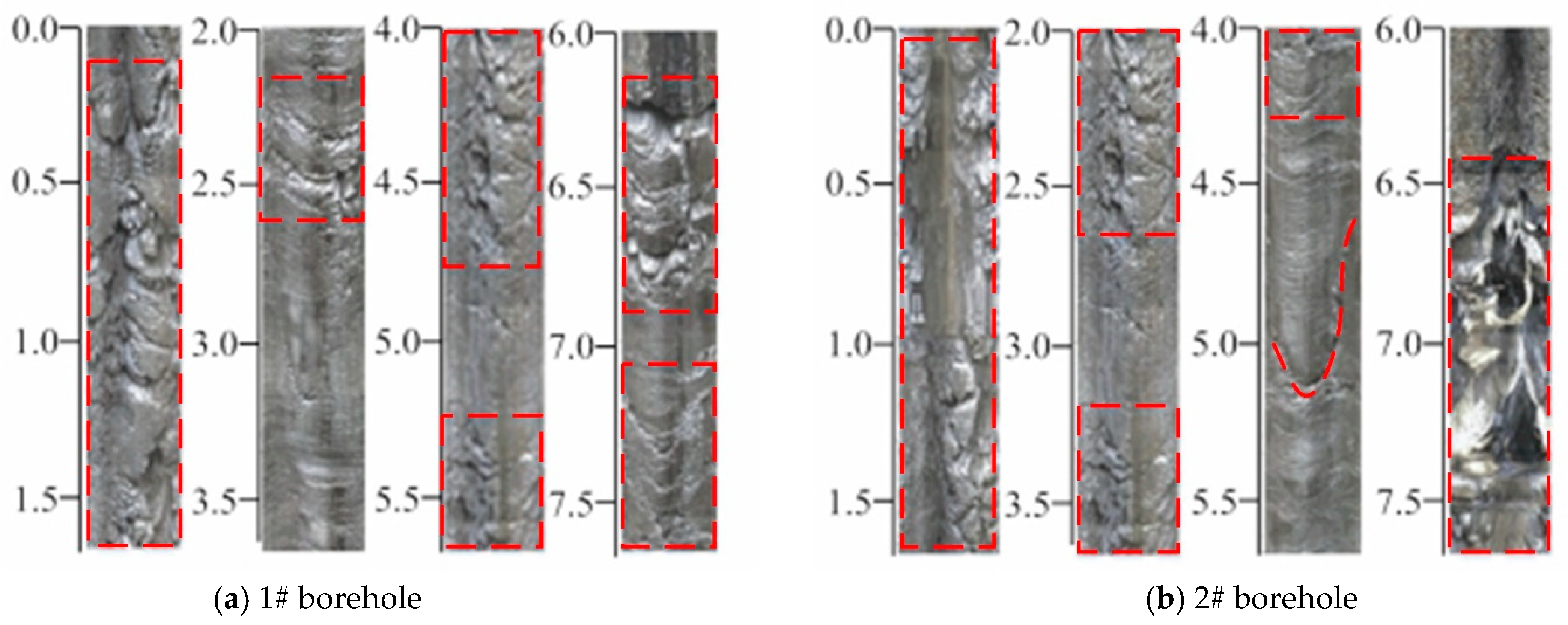
3.2. Borehole Television Imaging

A borehole television imager was used to observe the fractures of the roadway roof in the fault fracture zone. According to the development of fractures, the surrounding rock was divided into completed surrounding rock, fractured surrounding rock, and broken surrounding rock. Two boreholes were arranged in the roof of the roadway, with a diameter of 28 mm and a depth of 8.0 m. The observation results are shown in Figure 7.
The observation showed that the surrounding rock of the roadway is relatively broken, and there is basically no complete surrounding rock. In the range of 2.5 m, the surrounding rock of the roadway was seriously broken, and the anchoring effect of the bolt was seriously affected. In the range of 3~6 m, many groups of horizontal fissures were found in the surrounding rock. A wide range of delamination occurred in the range of 6.5~7.0 m, which was the main cause of roof collapse.

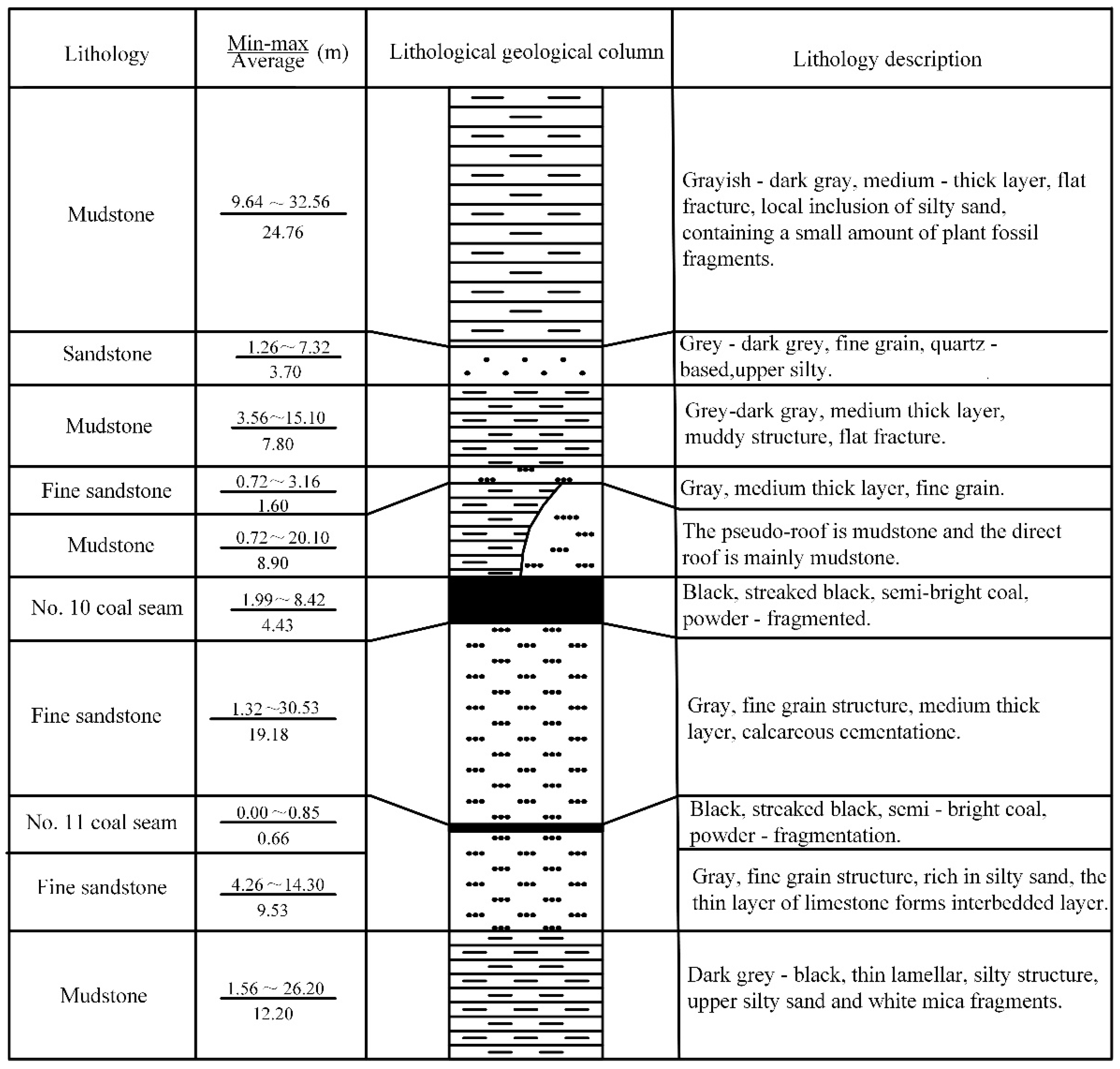
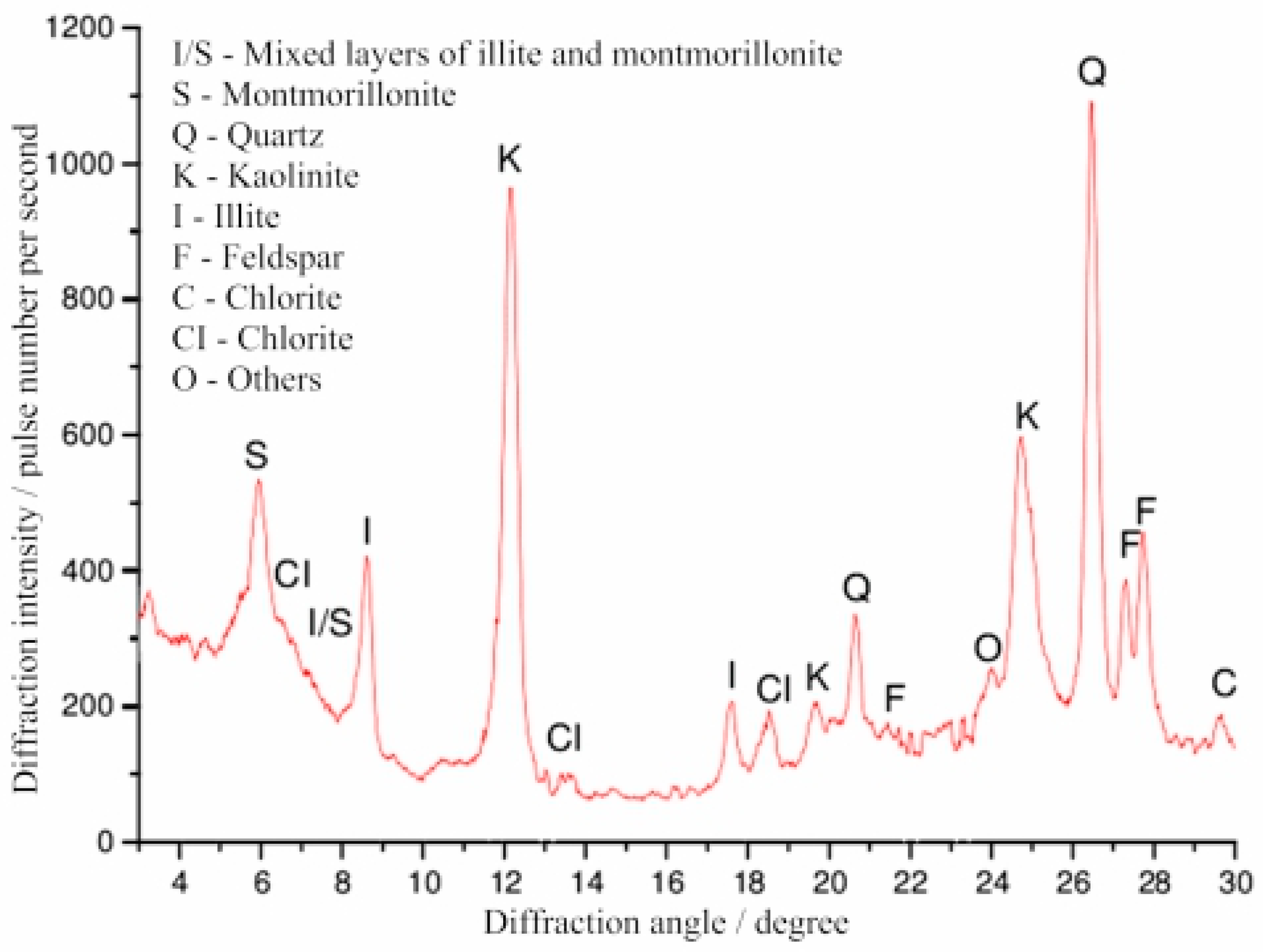
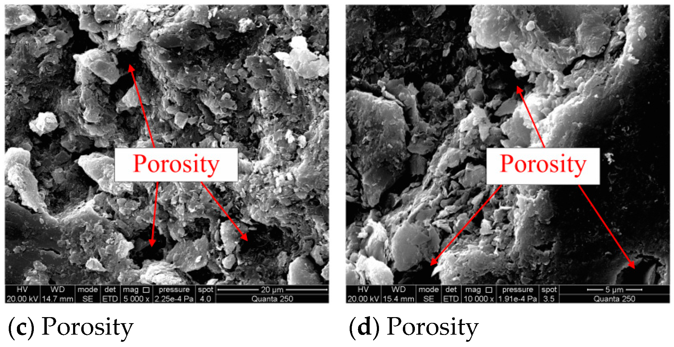
3.3. Lithological Analysis

The fault fracture zone contains a mixed lithology composed of mudstone, partially interbedded with carbonaceous mudstone or coal, with significant extrusion and wrinkling. During roadway excavation, the surrounding rock undergoes softening and swelling to water, which further decreases the strength of the surrounding rock. To determine the mineralogical composition of the mudstone, X-ray diffraction analysis was used, and the results are shown in Figure 8. This mineral composition test uses the D8Advance powder crystal X-ray diffractometer produced by the German Bruker Company (Karlsruhe, Germany). In terms of software, the international powder diffraction database (PDF), the powder crystal inorganic crystal structure database (ICSD), and the corresponding analysis software are configured. As shown in Figure 8, the mudstone was composed of a large amount of kaolinite, montmorillonite, and mixed layers of illite and montmorillonite. Among them, kaolinite has water absorption when it is dry, and has plasticity after moisture. The montmorillonite and mixed layer of illite and montmorillonite absorb water and expand rapidly, becoming paste-like. When the rock mass reacts with water physically and chemically, the properties of the rock mass change dramatically, and its volume expands over time, resulting in huge expansion pressure and large deformation. The volume expansion after hydration can exceed 50%.
Scanning electron microscopy (SEM) was used to observe the microscopic morphology and composition of the mudstone, as shown in Figure 9. The scanning electron microscopy used the QuantaTM 250 environmental scanning electron microscope produced by FEI Company (Hillsboro, OR, USA) to obtain the micro-morphological features under 2000 times magnification. Results show that intergranular fissures are more developed, and the rock has good water conductance. The expanded pores in the mudstone increase the porosity and the hydrolysis effect of the rock mass. The three-dimensional grid-like holes and the random accumulation between the particles reflect the good permeability of the mudstone and the development of the space channel. Whether it is kaolinite or montmorillonite, uneven expansion occurs after exposure to water, resulting in a large amount of pores. The appearance of these pores destroys the original internal structural system of the rock, which in turn promotes softening and disintegration.

3.4. Failure Mechanism of Roadway in the Fault Fracture Zone

Research results showed that the internal reasons for the failure of the roadway in the fault fracture zone were the high tectonic stress, broken surrounding rock, and poor lithology [35]. The ineffective support design was the external cause:
  • The horizontal stress in the fault fracture zone is the main stress of the in-situ stress field, which is almost perpendicular to the axial direction of the roadway. The high tectonic stress caused a stress concentration in the surrounding rock of the roadway, which caused the roof and floor of the roadway to fail first.
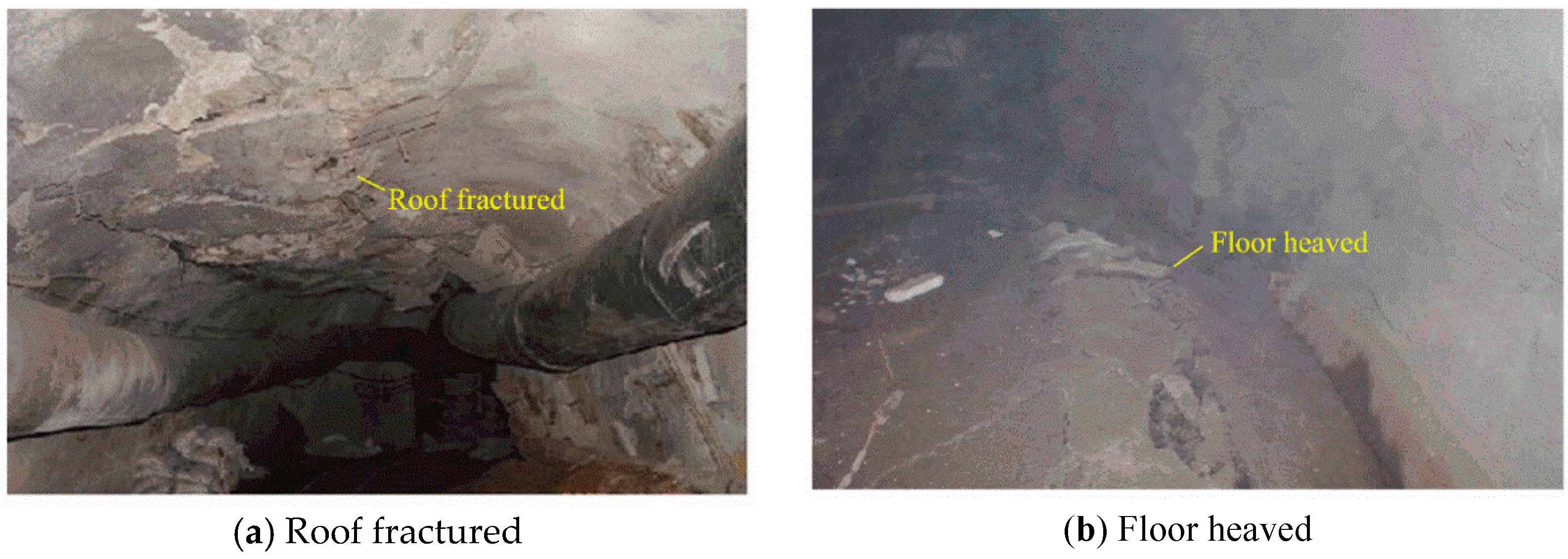
  • After the surrounding rock of the roadway was damaged, the fractures propagated and communicated with each other, and eventually formed a broken surrounding rock zone. The fractures caused by the crack propagation make the surrounding rock more broken. The broken surrounding rock loses its self-supporting ability, which caused the crack to expand to the deep surrounding rock, which further increases the damage range.
  • Mudstone is the main component of the surrounding rock, which contains a large number of kaolinite, montmorillonite, and mixed layers of illite and montmorillonite. The mudstone expands rapidly after water is absorbed, which promotes the phenomenon of softening and disintegration, further reducing the rock strength.
  • The borehole television imaging results showed that the surrounding rock is severely broken within 2.5 m, which affected the anchoring effect of the bolt. Large areas of delaminated and broken surrounding rocks can still be found beyond the 6.5 m depth of the surrounding rocks, exceeding the support range of the anchor cable. The support failure of the bolt and anchor cable caused large deformation of the roadway, which is also the main cause of the roof collapse.

4. Support Design

4.1. Roadway Support Design Principles

The original support only uses bolts and cables, which is not suitable for the support of roadways in the fractured area. Due to the unreasonable initial support design and lack of specificity, the roadway seriously deformed. During the roadway excavation process, a roof collapse accident occurred. Designing targeted support for this special geological condition is necessary. A new type of combined support technology is needed to ensure the stability of the roadway. According to the failure mechanism analysis, the following factors should be considered:
  • Grouting reinforcement: Field test results showed that broken surrounding rocks and poor lithology are the main causes of roadway damage. The best way to solve this problem is to use grouting reinforcement technology. Grouting reinforcement is mainly used to inject grout into the fractures through the grouting pressure, fill the fractures through the solidification of the grout, and cement the broken rock masses together to improve the bearing capacity of the rock mass itself, thereby achieving the purpose of surrounding rock reinforcement.
  • Pre-reinforced support: Field test results showed that the roof collapses with the roadway excavation due to the poor self-stabilizing capacity. Therefore, advanced grouting is used to support the uncovered roof. Advanced grouting is carried out on the broken surrounding rock in front of the excavation face so that the broken roof in the grouting section is cemented, preventing the surrounding rock from collapsing after excavation. Grouting also ensures the integrity of the roof after excavation, providing the supporting points for the subsequent grouting bolts and grouting cable anchors.
  • Rational support range: Field test results showed that the damage depth of the surrounding rock is large, and large-scale delamination and broken rock masses can still be observed at 6.5 m. The length of the anchor cable of the initial support design is only 6.2 m, which is less than the damage depth of the surrounding rock, making the support useless. Therefore, the new support range should be greater than the damage depth of the roadway.

4.2. Roadway Support Design

Based on the support principles, a new type of combined support technology is proposed. The new support includes advanced grouting, grouting bolts, and grouting cable anchors. The unexposed broken roof is supported by advanced grouting to strengthen the self-supporting capacity of the surrounding rock. Grouting bolts and grouting cable anchors are used to maintain the long-term stability of the roadway. The specific steps are as follows:
  • Advanced grouting support parameters: Advanced grouting support design is shown in Figure 10 and Figure 11. There are five grouting holes in the cross-section, including three grouting holes in the roof and two grouting holes in the ribs. The grouting hole is 0.3 m away from the roadway contour. The spacing between the grouting holes along the roadway axis is 1.5 m. The grouting holes have a diameter of 94 mm and a length of 12 m. The grouting holes are lifted upward by 10° in the vertical direction and inclined by 15° in the horizontal direction. The grouting pipes have a diameter of 73 mm and a length of 12 m. Multiple rows of 8 mm diameter grouting holes are drilled vertically along the wall of the grouting pipes. The anchorage length of each grouting pipe must be larger than 2 m.
  • U-shaped steel sheds support parameters: The U-shaped steel model used in this study is U29. As shown in Figure 10, the distance between U-shaped steel sheds along the roadway is 0.8 m. The overlap length of any two U-shaped steels is 0.5 m. The size of the steel back plate is 800 × 1200 × 80 mm.
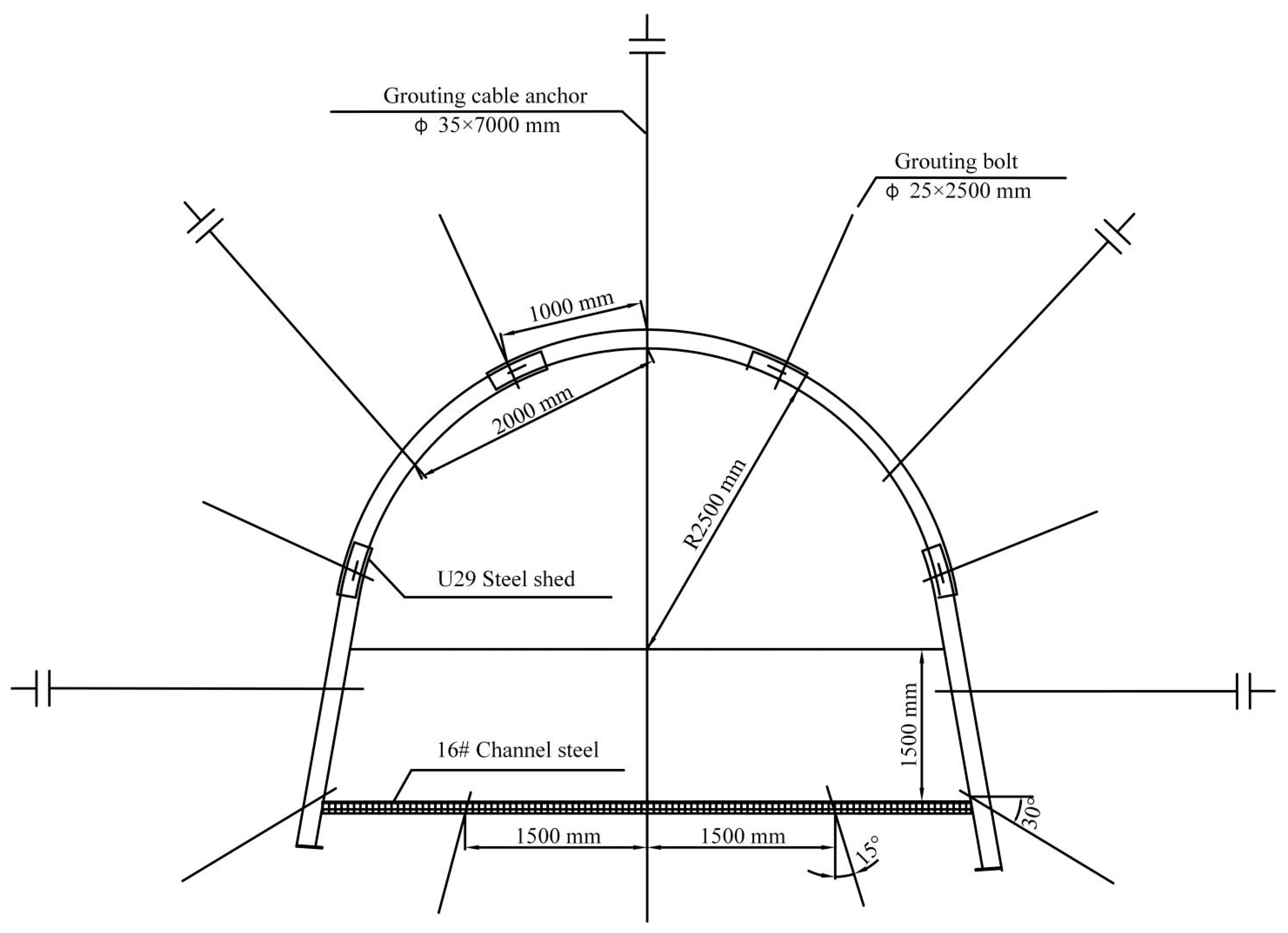
  • Grouting bolts’ parameters: Grouting bolts’ support is shown in Figure 12. There are fourteen grouting bolts in the roadway cross-section, including seven grouting bolts in the roof, four grouting bolts in the ribs, and three grouting bolts in the floor. The grouting bolts have a diameter of 25 mm and a length of 2.5 m. The distance between the grouting bolts in the roof and ribs along the roadway axis and the radial direction is 1.0 and 1.6 m, respectively. The distance between the grouting bolts in the floor along the roadway axis and the radial direction is 1.5 and 1.6 m, respectively. The anchorage length of each grouting bolt must be larger than 1.0 m. The primary concrete support is applied as soon as the grouting bolts pavement is finished.
  • Grouting cable anchors’ parameters: Grouting cable anchors’ support is shown in Figure 12. As shown in Figure 12, there are five grouting cable anchors in the roadway cross-section, including three grouting cable anchors in the roof and two grouting bolts in the ribs. The grouting cable anchors have a diameter of 35 mm and a length of 7.0 m. The distance between the grouting cable anchors in the roof and ribs along the roadway axis and the radial direction is 2.0 and 1.6 m, respectively. The anchorage length of each grouting cable anchor must be larger than 1.0 m. The secondary concrete support is applied as soon as the grouting cable anchors pavement is finished.
  • Grouting parameters: The grout material is composed of PO. 42.5 ordinary silicate cement and cement additive. The ratio of water/cement is 1:1.5. The cement additive is used with a dosage of 5% cement weight. The grouting pressure of advanced grouting, grouting bolt, and anchor cable is 8~10, 2~3, and 4~6 MPa, respectively.
After the advanced grouting support, roadway excavating is carried out. During the excavation process, support is performed by grouting bolts and grouting anchor cables. When the roadway is excavated to a distance of 10 m away from the grouting section, advanced grouting in the second stage is performed, and the cycle is sequentially performed until the roadway passes through the fault fracture zone. The choice of advanced grouting in the second stage at a distance of 10 m from the grouting section is to allow sufficient time for the cement solidification of the advanced grouting. The continuity and safety of the roadway excavation process can be guaranteed.

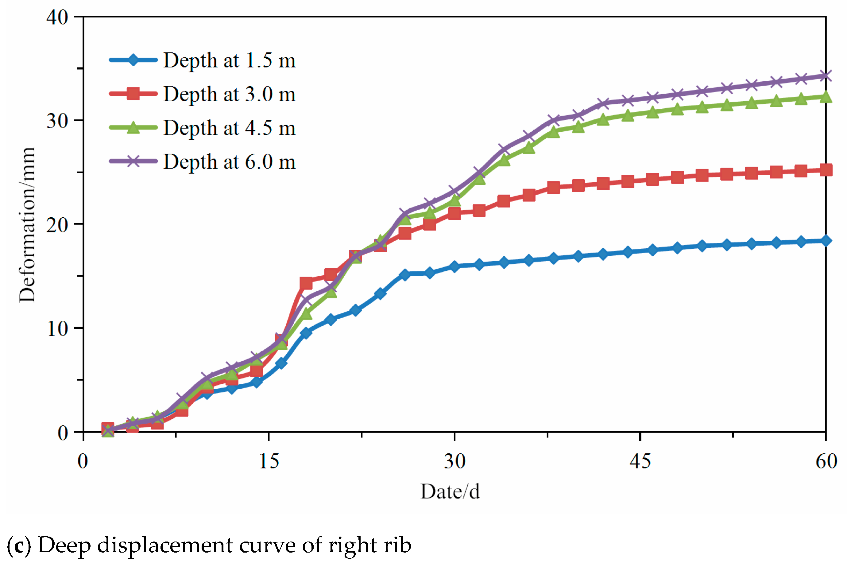
5. On-Site Monitoring

In order to monitor the effect of the new support design, a 100 m tested roadway of the north auxiliary blind inclined shaft in the fault fracture zone was selected. Taking the initial construction position as the starting point, observation sections was arranged to monitor surface displacement and deep displacement, as shown in Figure 1.
Multi-rod displacement meters were placed on the roof and the two ribs of the roadway, as shown in Figure 13. Before installation, a 30 mm mounting hole was drilled in the roof, and the borehole fixing device was sequentially sent to the predetermined position. After the reading device was fixed at the hole, the wire rope of each tested point was tightened, and the measuring ring was pushed on the borehole measuring device to the 100 mm position. Then, the wire rope and measuring ring were fixed with screws. After installation, the initial reading of each tested point can be read, and the difference between the measured value and the initial reading is the displacement value, which must be accurate to 0.2 mm. Convergence meters were placed on the roadway to monitor the surface displacement.
As shown in Figure 13, points B and C are the vertical data marks of the roof and floor of the roadway, and points D and E are the horizontal data marks of the two ribs of the roadway. Point A is the midpoint of BC and DE. The decrease of BC means the deformation of the roof and floor. The decrease of DE means the contraction of the two ribs. Measurements by a convergence meter are required to be accurate to 0.2 mm.
Figure 14 show the displacement curves of the deep surrounding rock in the monitored section. Figure 14a shows that the relative displacement within 6 m of the surrounding rock of the roadway roof is less than 30 mm during the observation period, and Figure 14b,c show that the relative displacement within 6 m of the surrounding rock of the roadway gang is less than 40 mm. After 40 days, displacement of the roadway surrounding rock began to converge, indicating that the overall strength of the roadway surrounding rock after grouting was improved, and the roadway surrounding rock was effectively controlled. The support method can effectively maintain roadway stability.
The curve of the displacement observation of the surrounding rock surface is shown in Figure 15.
The deformation from the two ribs at the monitored section is 75 mm, and the deformation from the roof–floor is 161 mm. After 40 days of roadway construction, roadway deformation began to converge. Roadway deformation after support is obviously reduced, and deformation speed is effectively controlled, making the roadway much safer overall. During the monitoring period, there is no obvious deformation of the surrounding rock of the roadway after adopting the new support design, indicating that the new support design can control the deformation and ensure the long-term stability of the roadway. The effectiveness of the new support design can be visually observed in Figure 16.

6. Conclusions

Taking the blind inclined shaft in the north wing of the 106 mining area of the Yuandian no.2 coal mine as an example, roadway support technology in the fault fracture zone is studied. The buried slope of the mining area is about 600 m deep and passes through the LWF54 fault. The initial roadway support structure was composed of anchor mesh and cable combined with a spray support. With this roadway support structure adopted, the roof collapse and the surrounding rock deformation were clearly observed during the excavation process. The initial support design cannot meet the roadway support requirements in the fault fracture zone. Based on the on-site geological conditions (in-situ stress test, borehole television imaging, lithology analysis), the failure mechanism of the roadway tunnel in the fault fracture zone was studied. A new type of combined support technique was proposed and monitored in the test roadway:
  • Field investigations and tests showed that the tectonic stress state in the fault fracture zone was complex. The horizontal stress was about 1.55 times the vertical stress, and the angle between the main roadway axis and the main horizontal stress was 84.4°. The surrounding rock was severely broken within 2.5 m, and large-scale delamination can still be found beyond the 6.5 m depth of the surrounding rocks. Mudstone is the main component of the surrounding rock, which contained a large number of kaolinite, montmorillonite, and mixed layers of illite and montmorillonite. The internal causes for the failure of the roadway in the fault fracture zone were the high tectonic stress, broken surrounding rock, and poor lithology, and the external cause was the unreasonable support design.
  • According to the support principles of grouting reinforcement, pre-reinforced support, and reasonable support range, a new type of combined support technology was proposed, which included advanced grouting, grouting bolts, and grouting anchor cables. The unexposed broken roof is supported by advanced grouting to strengthen the self-supporting capacity of the surrounding rock. U-shaped steel support is used to support the roadway immediately after excavation to limit the deformation and collapse of surrounding rock. Grouting bolts and grouting cable anchors are used to maintain the long-term stability of the roadway. By using the new combined support technology, the broken surrounding rock in the fault fracture area is cemented into a complete rock mass, and the support capacity of the whole support system is improved.
  • On-site industrial tests were carried out on a 100 m tested roadway. Test results show that the new support scheme is more effective than the initial support scheme, and the deformation of the roadway surrounding rock is significantly reduced under the new support scheme. With the new support technology, the safety hazard of roof collapse after roadway excavation can be effectively solved, and the long-term stability of the roadway was ensured. The results provide a reference for the support design of roadway engineering in similar geologic conditions.

Author Contributions

Conceptualisation, K.W. and L.W.; Data curation, K.W. and B.R.; Formal analysis, K.W.; Writing—original draft, K.W. All authors have read and agreed to the published version of the manuscript.

Funding

This paper was funded by the National Key Research and Development Program of China (2017YFC0603004).

Institutional Review Board Statement

Not applicable.

Data Availability Statement

No new data were created or analysed in this study. Data sharing is not applicable to this article.

Acknowledgments

We thank all project partners for many fruitful discussions.

Conflicts of Interest

The authors declare no conflict of interest.

References

  1. Jiang, B.; Gu, S.; Wang, L.; Zhang, G.; Li, W. Strainburst process of marble in tunnel-excavation-induced stress path considering intermediate principal stress. J. Cent. South Univ. 2019, 26, 984–999. [Google Scholar] [CrossRef]
  2. Kang, Y.; Liu, Q.; Gong, G.; Wang, H. Application of a combined support system to the weak floor reinforcement in deep underground coal mine. Int. J. Rock Mech. Min. Sci. 2014, 71, 143–150. [Google Scholar] [CrossRef]
  3. Song, R.; Zhang, D.; Wen, M. The cusp catastrophe theory analysis for instability of deep-buried tunnels surrounding rock through fault fracture zone. China Civ. Eng. J. 2015, 48, 289. [Google Scholar]
  4. Zhang, C.; Tu, S. Control technology of direct passing karstic collapse pillar in longwall top-coal caving mining. Nat. Hazards 2016, 84, 17–34. [Google Scholar] [CrossRef]
  5. Zhang, W.; He, Z.; Zhang, D.; Qi, D.; Zhang, W. Surrounding rock deformation control of asymmetrical roadway in deep three-soft coal seam: A case study. J. Geophys. Eng. 2018, 15, 1917–1928. [Google Scholar] [CrossRef] [Green Version]
  6. Liu, Q.; Lu, C.; Lu, H. Application and analysis of ground surface pre-grouting strengthening deep fault fracture zone. Chin. J. Rock Mech. Eng. 2013, 32, 3688–3695. [Google Scholar]
  7. Liu, Q.; Zhang, W.; Lu, X.; Fu, J. Safety monitoring and stability analysis of large-scale roadway in fault fracture zone. Chin. J. Rock Mech. Eng. 2010, 29, 1954–1962. [Google Scholar]
  8. Roy, C.K.; Uddin, M.G.; Roy, B.; Dean, T.R. Evaluating Aspect Mining Techniques: A Case Study. In Proceedings of the IEEE International Conference on Program Comprehension, Buenos Aires, Argentina, 22–23 May 2017. [Google Scholar]
  9. Seon-Bok, L.; Hae-Chan, J. Case Study of the Longest Roadway Tunnel in Korea, Baehuryeong Tunnel. Tunn. Undergr. Space 2005, 15, 432–440. [Google Scholar]
  10. Wang, Q.; Qu, L.; Guo, H.; Wang, Q. Grouting reinforcement technique of Qingdao Jiaozhou bay subsea tunnel. Chin. J. Rock Mech. Eng. 2011, 30, 790–802. [Google Scholar]
  11. Xue, Y.; Li, S.; Su, M.; Zhang, X.; Zhao, Y.; Xu, Z.; Li, Z.; Zhang, G. Stduy of comprehensive test method for grouting effect of water filling fault in Qingdao Kiaochow Bay subsea tunnel. Chin. J. Rock Mech. Eng. 2011, 30, 1382–1388. [Google Scholar]
  12. Zhou, R.; Cheng, B.; Ye, G.; Wu, Q. Time effect of water bursting in fault rupture zone. J. Eng. Geol. 2000, 8, 411–415. [Google Scholar]
  13. Wang, F.; Zhang, C.; Wei, S.; Zhang, X.; Guo, S. Whole section anchor–grouting reinforcement technology and its application in underground roadways with loose and fractured surrounding rock. Tunn. Undergr. Space Technol. 2016, 51, 133–143. [Google Scholar]
  14. Yao, Q.; Li, X.; Pan, F.; Wang, T.; Wang, G. Deformation and failure mechanism of roadway sensitive to stress disturbance and its zonal support technology. Shock Vib. 2016, 2016. [Google Scholar] [CrossRef] [Green Version]
  15. Zhang, S.; Zhang, D.; Wang, H.; Liang, S. Discrete element simulation of the control technology of large section roadway along a fault to drivage under strong mining. J. Geophys. Eng. 2018, 15, 2642–2657. [Google Scholar] [CrossRef] [Green Version]
  16. Piotr, M.; Łukasz, O.; Piotr, B. Modelling the small throw fault effect on the stability of a mining roadway and its verification by in situ investigation. Energies 2017, 10, 2082. [Google Scholar] [CrossRef] [Green Version]
  17. Wang, Y.; Jing, H.; Su, H.; Xie, J. Effect of a fault fracture zone on the stability of tunnel-surrounding rock. Int. J. Geomech. 2016, 17, 04016135. [Google Scholar] [CrossRef]
  18. Qian, D.; Zhang, N.; Shimada, H.; Wang, C.; Sasaoka, T.; Zhang, N. Stability of goaf-side entry driving in 800-m-deep island longwall coal face in underground coal mine. Arab. J. Geosci. 2016, 9, 82. [Google Scholar] [CrossRef]
  19. Qian, D.; Zhang, N.; Pan, D.; Xie, Z.; Shimada, H.; Wang, Y.; Zhang, C.; Zhang, N. Stability of deep underground openings through large fault zones in argillaceous rock. Sustainability 2017, 9, 2153. [Google Scholar] [CrossRef] [Green Version]
  20. Das, A.J.; Mandal, P.K.; Sahu, S.P.; Kushwaha, A.; Bhattacharjee, R.; Tewari, S. Evaluation of the Effect of Fault on the Stability of Underground Workings of Coal Mine through DEM and Statistical Analysis. J. Geol. Soc. India 2018, 92, 732–742. [Google Scholar] [CrossRef]
  21. Emamjome, F.; Andrews, R.; Hofstede, A.H.M.T. A Case Study Lens on Process Mining in Practice. In Proceedings of the OTM Confederated International Conferences “On the Move to Meaningful Internet Systems”, Rhodes, Greece, 21–25 October 2019. [Google Scholar]
  22. Heenan, D.M.; Xu, M. Grouting to Minimize Settlements Prior to Tunnel Excavation—A Case Study. In Proceedings of the International Conference on Grouting & Ground Treatment, New Orleans, LA, USA, 10–12 February 2003. [Google Scholar]
  23. Islam, M.R.; Shinjo, R. Numerical simulation of stress distributions and displacements around an entry roadway with igneous intrusion and potential sources of seam gas emission of the Barapukuria coal mine, NW Bangladesh. Int. J. Coal Geol. 2009, 78, 249–262. [Google Scholar] [CrossRef]
  24. Qian, D.; Zhang, N.; Zhang, M.; Shimada, H.; Cao, P.; Chen, Y.; Wen, K.; Yang, S.; Zhang, N. Application and evaluation of ground surface pre-grouting reinforcement for 800-m-deep underground opening through large fault zones. Arab. J. Geosci. 2017, 10, 285. [Google Scholar] [CrossRef]
  25. Liu, J.; Jing, J.; Feng, Y.; Wu, L.; Zhang, P. Study on grouting anchor cable supporting technology of roadway through extra large fault fracture zone. In Proceedings of the Aishan Academic Forum–Project on Mine Disaster Prevention and Control, Qingdao, China, 17–20 October 2014. [Google Scholar]
  26. Ma, Z.; Jiang, Y.; Du, W.; Zuo, Y.; Kong, D. Fracture evolution law and control technology of roadways with extra thick soft roof. Eng. Fail. Anal. 2018, 84, 331–345. [Google Scholar] [CrossRef]
  27. Wang, Q.; Pan, R.; Jiang, B.; Li, S.; He, M.; Sun, H.; Wang, L.; Qin, Q.; Yu, H.; Luan, Y. Study on failure mechanism of roadway with soft rock in deep coal mine and confined concrete support system. Eng. Fail. Anal. 2017, 81, 155–177. [Google Scholar] [CrossRef]
  28. Wang, H.; Zheng, P.-q.; Zhao, W.-j.; Tian, H.-m. Application of a combined supporting technology with U-shaped steel support and anchor-grouting to surrounding soft rock reinforcement in roadway. J. Cent. South Univ. 2018, 25, 1240–1250. [Google Scholar] [CrossRef]
  29. Behera, P.K.; Sarkar, K.; Singh, A.K.; Verma, A.K.; Singh, T.N. Dump slope stability analysis—A case study. J. Geol. Soc. India 2016, 88, 725–735. [Google Scholar] [CrossRef]
  30. Sears, M.M.; Rusnak, J.; Dyke, M.V.; Rashed, G.; Mohamed, K.; Sloan, M. Coal rib response during bench mining: A case study. Int. J. Min. Sci. Technol. 2018, 28, 107–113. [Google Scholar] [CrossRef] [PubMed]
  31. Xiao, L.; Li, S.; Zeng, X.; Lin, D. Corrosion Inestigation and Mechanical Behavior Test on Support of Bolts in Underground Drift. Chin. J. Rock Mech. Eng. 2008, 27, 3. [Google Scholar]
  32. Shen, B. Coal mine roadway stability in soft rock: A case study. Rock Mech. Rock Eng. 2014, 47, 2225–2238. [Google Scholar] [CrossRef]
  33. Yang, J. Analysis on Excavation and Support Technique of the Fault and Crushing Zone in Cimushan Tunnel. Chin. J. Undergr. Space Eng. 2011, 7, 361–365. [Google Scholar]
  34. Zhang, C.Y.; Wu, M.L.; Liao, C.T. In-situ stress measurement and study of stress state characteristics of Jin⁃ chuan No. 3 mine. Rock Soil Mech. 2013, 34, 3254–3260. [Google Scholar]
  35. Wang, Y.; Liu, B.G.; Qi, Y. A Risk Evaluation Method with an Improved Scale for Tunnel Engineering. Arab. J. Sci. Eng. 2018, 43, 2053–2067. [Google Scholar] [CrossRef]
Figure 1. Simplified map of Yuandian no.2 coal mine and layout of the test roadway.
Energies 14 03767 g001aEnergies 14 03767 g001b
Figure 2. Stratigraphic columns of the 106 mining area.
Energies 14 03767 g002
Figure 3. Initial supporting design of the roadway.
Energies 14 03767 g003
Figure 4. Roadway failure characteristics under the initial supporting design.
Energies 14 03767 g004
Figure 5. Displacement curve of deep surrounding rock in the roof with the initial support.
Energies 14 03767 g005
Figure 6. Stress relief curve of tested point 1.
Energies 14 03767 g006
Figure 7. Fractures of surrounding rocks from borehole television imager.
Energies 14 03767 g007
Figure 8. Mudstone mineral composition X-diffraction pattern.
Energies 14 03767 g008
Figure 9. SEM photomicrographs of mudstone.
Energies 14 03767 g009aEnergies 14 03767 g009b
Figure 10. Roadway grouting hole layout.
Energies 14 03767 g010
Figure 11. Schematic diagram of advanced grouting construction.
Energies 14 03767 g011
Figure 12. Roadway full-section support diagram.
Energies 14 03767 g012
Figure 13. Monitoring layout of multi-point displacement and surface displacement.
Energies 14 03767 g013
Figure 14. Displacement curve of the deep surrounding rock in the section roadway.
Energies 14 03767 g014aEnergies 14 03767 g014b
Figure 15. Surface displacement curves.
Energies 14 03767 g015
Figure 16. Tested support scheme.
Energies 14 03767 g016
Table 1. Technical characteristics of the in-situ stress-tested point in the 106 mining area.
Tested Point NumberPoint Depth (m)Tested Point PositionDrilling
Hole Depth (m)Azimuth (°)Inclination (°)
1#511The north transportation blind inclined shaft8.01285
2#553The north auxiliary blind inclined shaft8.31455
3#559The north air return blind inclined shaft8.31335
Table 2. Summary of rock mechanics parameters.
Core GroupElastic Modulus (GPa)Poisson’s Ratio
1#27.900.25
2#28.530.23
3#28.640.23
Table 3. In-situ stress test results.
Tested Point NumberTested Point PositionPoint Depth
(m)
Principal StressVertical Stress
(MPa)
Principal StressSize
(MPa)
Azimuth
(°)
Inclination (°)
1#The north transportation blind inclined shaft511σ120.0481.369.3612.77
σ211.2288.7183.29
σ310.31278.328.93
2#The north auxiliary blind inclined shaft553σ120.2588.256.7313.82
σ213.368.7183.29
σ311.00276.667.34
3#The north air return blind inclined shaft559σ121.7685.138.2513.97
σ213.4829.6377.01
σ311.48274.857.55
Publisher’s Note: MDPI stays neutral with regard to jurisdictional claims in published maps and institutional affiliations.

