Article

Fault Detection Algorithm for Multiple-Simultaneous Refrigerant Charge and Secondary Fluid Flow Rate Faults in Heat Pumps

1
Department of Mechanical Engineering, Kwame Nkrumah University of Science and Technology, Kumasi AK-039-5028, Ghana
2
Graduate School of Mechanical Engineering, Hanbat National University, Daejeon 34158, Korea
3
Department of Architecture, Korea University, Seoul 02741, Korea
4
Department of Mechanical Engineering, Hanbat National University, Daejeon 34158, Korea
*
Author to whom correspondence should be addressed.
Energies 2021, 14(13), 3877; https://doi.org/10.3390/en14133877
Submission received: 25 May 2021 / Revised: 23 June 2021 / Accepted: 24 June 2021 / Published: 28 June 2021

Abstract

:
The detection and diagnosis of faults is becoming necessary in ensuring energy savings in heat pump units. Faults can exist independently or simultaneously in heat pumps at the refrigerant side and secondary fluid flow loops. In this work, we discuss the effects that simultaneous refrigerant charge faults and faults associated with the flow rate of secondary fluids have on the performance of a heat pump operating in summer season and we developed a correlation to detect and diagnose these faults using multiple linear regression. The faults considered include simultaneous refrigerant charge and indoor heat exchanger secondary fluid flow rate faults (IFRFs), simultaneous refrigerant charge and outdoor heat exchanger secondary fluid flow rate faults (OFRFs) and simultaneous refrigerant charge, IFRF and OFRF. The occurrence of simultaneous refrigerant charge fault, IFRF and OFRF caused up to a 5.7% and 8% decrease in cooling capacity compared to simultaneous refrigerant charge and indoor heat exchanger secondary fluid flow rate faults, and simultaneous refrigerant charge and outdoor heat exchanger secondary fluid flow rate faults, respectively. Simultaneous refrigerant charge fault, IFRF and OFRF resulted in up to an 11.6% and 5.9% decrease in COP of the heat pump unit compared to simultaneous refrigerant charge fault and IFRF, and simultaneous refrigerant charge fault and OFRF, respectively. The developed FDD correlations accurately predicted the simultaneous refrigerant charge and faults in the flow rate of the secondary fluid within an error margin of 7.7%.

1. Introduction

Performance of ground source heat pumps (GSHP) decreases drastically because of the development of faults either at the time of installation or during operation of the heat pump, which is an integral component of the GSHP system. The existence of faults in the heat pump unit, therefore, results in higher energy consumption in the GSHP system, less comfort levels in humans, low productivity, increased operation and maintenance cost and reduced indoor air quality that greatly affects the health of occupants.
It is estimated that the energy consumption of HVAC systems operating with faults can increase up to 30% [1,2]. This is a great source of worry which has resulted in automating heat pump fault detection and diagnosis (FDD) models. A lot of FDD models have, therefore, been developed and applied to HVAC systems [3,4,5,6,7,8,9,10,11,12,13]. Shamandi and Jazi [14] developed simulated refrigerant charge and compressor leakage faults in a refrigeration system. The study established that superheat and subcooling were greatly affected by refrigerant charge fault, dirty condenser fault and evaporator air flow rate. Zhao [15] formulated a method to detect single faults in chillers using a statistical method, support vector regression analysis and control charts. Sellami et al. [16] formulated FDD algorithm for singular faults in a refrigerator. Sun et al. [17] studied faults in refrigeration systems for supermarkets and catalogued datasets for refrigerants faults. Li et al. [18] investigated the problem of using labelled and unlabelled data for fault detection in HVAC systems and introduced a multiclass classifier into the modified generative adversarial network method to be able to simultaneously use labelled and unlabelled data sets for fault detection in building HVAC systems. Bellanco et al. [19] reviewed various heat pump faults and their effects on system performance. Authors discussed FDD models, analysed the type of instruments needed for various laboratory and field faults and investigated sensors needed for FDD implementation. The study found that more research is needed to improve the use of performance criteria for detection of faults and conducting additional studies on the use of sensors for fault detection and diagnosis in heat pump systems. Dudley et al. [20] investigated the use of semi-supervised learning approach to detect faults in HVAC systems. Authors tested and validated the proposed technique using statistical tools. Eom et al. [21] developed a refrigerant charge fault detection model using convolutional neural networks to improve on the shortcomings of various artificial neural network models for refrigerant charge faults in heat pumps. The proposed model had an almost perfect accuracy level with about 3.1% error in predicting refrigerant charge faults in heat pumps.
Most FDD models focus on single faults, with few available works in open literature focusing on multiple-simultaneous faults. Zhao et al. [22] formulated an FDD method for a chiller system using a decoupling-based FDD model. The FDD model diagnosed multiple simultaneous refrigerant faults. Han et al. [23] used a multi-label technique and support vector machine to formulate an FDD model for multiple faults. The developed FDD model was applied to investigate multiple faults in a chiller using data from an ASHRAE project. Boahen et al. [24] adopted regression analysis to formulate an FDD algorithm for faults in the flow rate of the secondary fluids in a heat pump unit. The FDD algorithm could detect single and multiple faults in the flow rate of the secondary fluid within an error threshold of ±6.4%. Miyata et al. [25] used FDD algorithms for fault detection in chiller performance, heat exchanger, pump and the temperature sensor of a heating system. The FDD algorithm was developed using a convolutional neural network with simulated data and validated using real data. The FDD algorithm had about 98.7% accuracy in detecting single and multiple faults.
In the studies conducted by Mowris et al. [26] and Roth et al. [27], it was realized that about 72% of cooling systems were operating with combined refrigerant leakage and evaporator airflow rate faults, reducing the performance of these cooling systems by about 10%. This shows that an FDD algorithm for multiple refrigerant charge and secondary fluid flow rate faults is inevitable and can go a long way to improve energy savings in cooling systems. However, for heat pumps, studies on FDD algorithms for the detection of multiple faults in the refrigerant charge and flow rate of secondary fluids is limited in the literature. This work, therefore, uses multiple regression tools to model an FDD algorithm for multiple faults occurring simultaneously in the refrigerant charge and flow rate of the secondary fluid in a heat pump unit. The study discusses, in detail, the effect of these faults on the performance of the heat pump. The developed FDD algorithm is specific to the heat pump used in this study, however, it will serve as a guide to researchers in developing multiple-simultaneous refrigerant charge and secondary fluid flow rate FDD algorithms for other heat pump units.

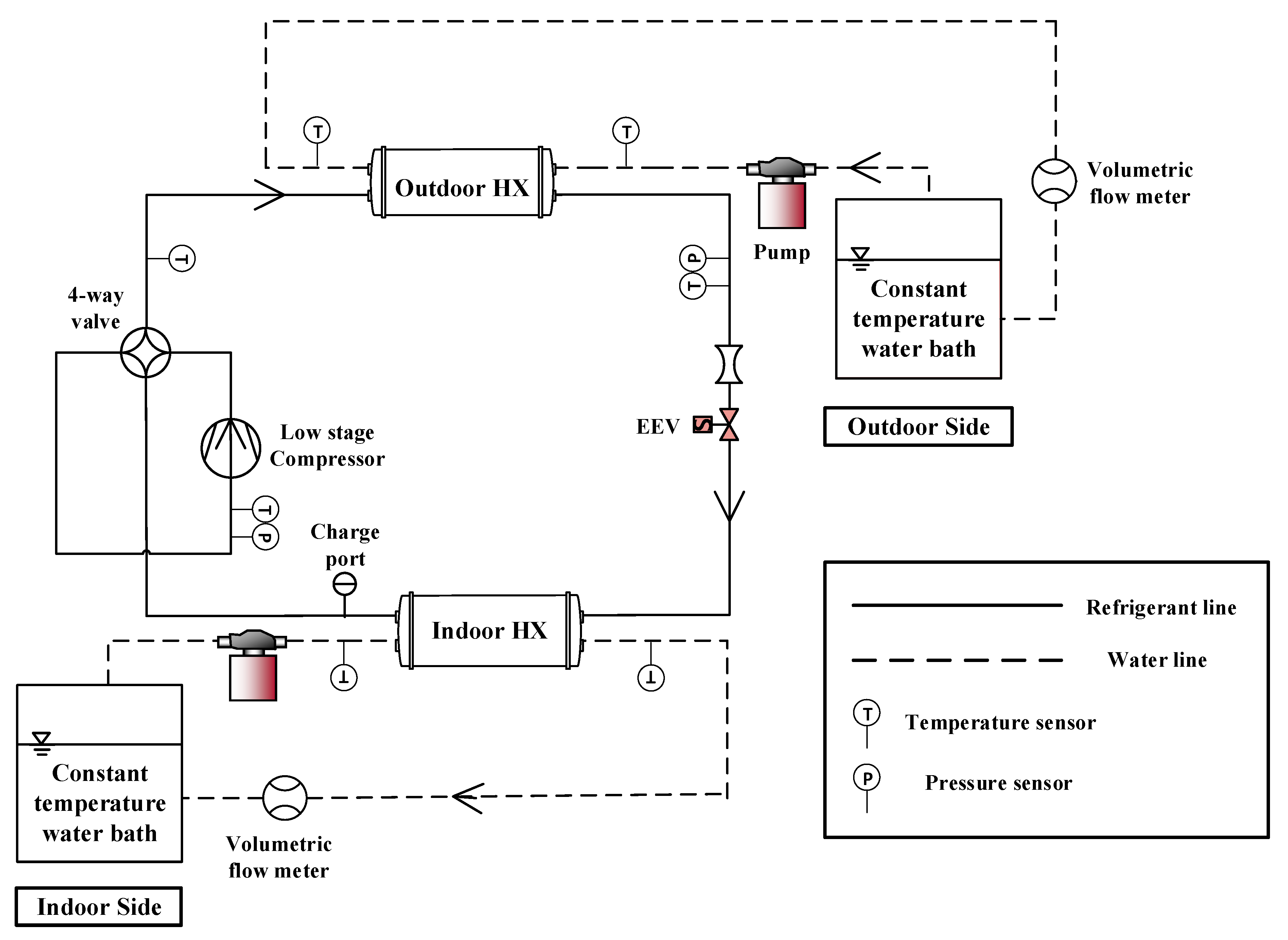
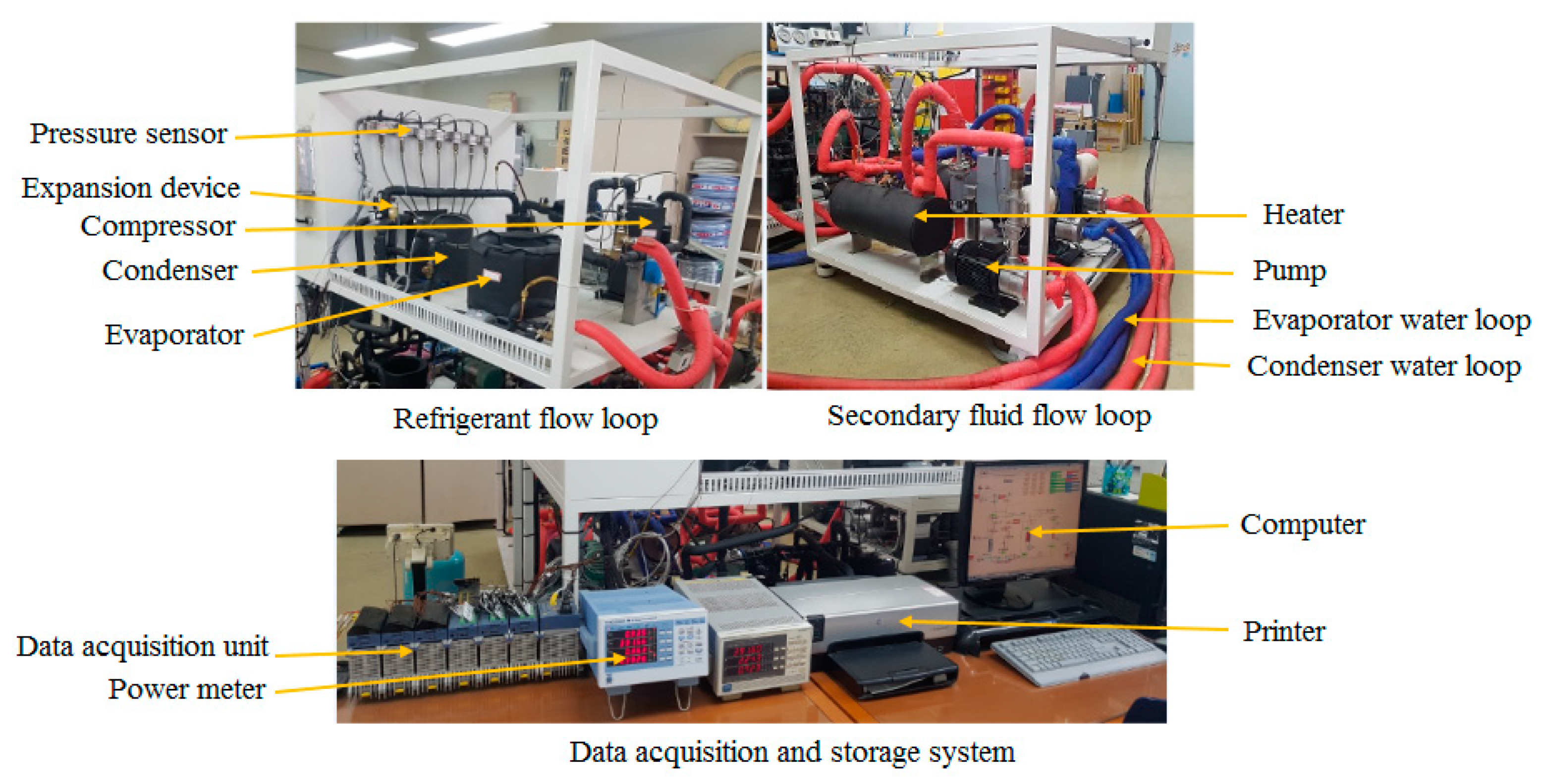
2. Experimental Setup and Methodology

A test rig was made to study multiple refrigerant charge faults and faults in the flow rate of the secondary fluid that simultaneously occur in a heat pump unit and develop an FDD model for these faults. The experimental rig had a refrigerant loop consisting of a compressor, outdoor heat exchanger (ODHX), which acted as the condenser, electronic expansion device (EEV) and an indoor heat exchanger (IDHX), which was used as the evaporator as shown in Figure 1. It also had secondary fluid flow loops consisting of closed-loop water flow paths simulated using constant temperature water baths for the IDHX and ODHX. A photograph of the refrigerant flow loop, secondary fluid flow loop and data acquisition and storage system of the heat pump is presented in Figure 2. The heat pump unit adopted refrigerant R410A as the working fluid, while brine consisting of an ethylene glycol concentration of 43% was used as the secondary fluid for the IDHX and ODHX. The experiment was conducted in cooling mode at standard outdoor heat exchanger inlet water temperature (OD EWT) and indoor heat exchanger inlet water temperature (ID EWT) conditions of 25 ° C of 12 ° C , respectively. The standard entering water temperature conditions were selected in relation to ISO 13256-2 [28] and NR GT 101 [29]. The types of faults investigated were combined fault in the refrigerant charge amount and the IDHX secondary fluid flow rate (IFRF), combined fault in the refrigerant charge amount and the brine flow rate in the ODHX (OFRF) and combined fault in the refrigerant charge amount, IFRF and OFRF.
Table 1 shows the test conditions used for this study. To begin with, the reference values of the refrigerant charge amount flow rates of the secondary fluid were determined and represented as 100% at the standard OD EWT and ID EWT conditions. The optimum charge amount was found to be 4700 g, the reference ODHX secondary fluid flow rate (SFFR) was found to be 8LPM, and the reference IDHX SFFR was also found to be 8LPM. Combined refrigerant charge fault and IFRF was simulated by simultaneously changing the amount of refrigerant at 70%, 80%, 90%, 100%, 110% and 120% of the base value and the IDHX SFFR at 60%, 80%, 100%, 120% and 140% of the base value. Combined refrigerant charge fault and OFRF was simulated by simultaneously altering the amount of refrigerant at 70%, 80%, 90%, 100%, 110% and 120% of the base value and the ODHX SFFR at 60%, 80%, 100%, 120% and 140% of the base value. Lastly, the combined refrigerant charge fault, IFRF and OFRF was simulated by simultaneously changing the charge amount from 60% to 80%, 100%, 120% and 140% of the base value, the IDHX SFFR at 60%, 80%, 100%, 120% and 140% of the base value and the ODHX SFFR at 60%, 80%, 100%, 120% and 140% of the base value. The OD EWT was varied at 20 ° C , 25 ° C , 30 ° C and 35 ° C to investigate how the performance of the heat pump is affected by combined changes in the outdoor temperature and the investigated faults.
During the conduct of each experiment, the electronic expansion valve (EEV) was varied to achieve a constant superheat of 7 ° C to serve as a control parameter for the experiment. The experimental setup had sensors installed in it to measure the heat pump’s performance according to the variation of the imposed faults. T-type thermocouples, pressure transducers, flow meter and power meter were used, respectively, in the refrigerant side, for the measurement of temperature, pressure, flow rate and compressor power. The flow loop of the secondary fluid had flow meters and RTD sensors connected for measuring brine flow rate and temperature, respectively. Accuracies of sensors used for the experiment are presented in Table 2. The test data were recorded and kept on a computer within 3 s scanning time and 30 min storage time by a Yokogawa MX100 data acquisition system. Equation (1) shows the data reduction and determination of the capacity of the heat pump. The cooling capacity was determined using density and specific heat capacity of water, flow rate and difference in the temperature of the brine in the evaporator. The coefficient of performance was calculated as the capacity of the heat pump divided by the electrical power consumed by the compressor as shown in equation (2). Equation (3) [30] was used to assess the uncertainty of the heat pump parameters. The coefficient of performance had an uncertainty of 3.0% while uncertainty of the cooling capacity was found to be 2.8%.
Q = ρ × C p × L P M × ( L W T E W T ) 60000  
C O P = Q W  
U = i = 1 n ( U i x i ) 2

3. Results and Discussions

3.1. Performance of the Heat Pump Unit According to the Various Faults

3.1.1. Simultaneous Refrigerant Charge Fault and IDHX Secondary Fluid Flow Rate Fault

As individual faults exist in heat pumps, the simultaneous occurrence of faults can also occur when operating heat pumps. For a combined fault in the refrigerant charge amount and the secondary fluid of the IDHX (IFRF), the following faults may exist simultaneously: refrigerant leak and reduced IFRF, refrigerant leak and increased IFRF, refrigerant overcharge and reduced IFRF and refrigerant overcharge and increased IFRF. Each of these simultaneously occurring faults will differently affect the heat pump’s performance and operating parameters.
Figure 3 and Figure 4, respectively, show the deviation in the reference capacity and COP of the heat pump according to four simultaneously occurring faults. The reference cooling capacity and COP of the heat pump were 3.1 kW and 3.43, respectively. The cooling capacity and COP generally decreased at refrigerant leak and reduced IFRF, refrigerant leak and increased IFRF and refrigerant overcharge and reduced IFRF due to the dominant reduction in COP and capacity because of the refrigerant charge faults. However, the capacity and COP increased at refrigerant overcharge and IFRF above 120% of the reference value. The cooling capacity and COP decreased greatly at higher refrigerant leak (70% refrigerant charge ratio) and highly reduced IFRF (60% IDHX flow rate). This combined fault resulted in the worst performance of the heat pump. At 90% refrigerant charge ratio (10% refrigerant leakage) and 80% indoor heat exchanger (IDHX) secondary fluid flow rate (SFFR), the capacity decreased by 10%. However, cooling capacity decreased by 19% at a 90% refrigerant charge ratio and 60% IDHX SFFR. At 80% IDHX SFFR, capacity decreased by 10%, 21% and 30% at 10%, 20% and 30% refrigerant leak, respectively. Nonetheless, at 60% IDHX SFFR, the cooling capacity decreased by 19%, 29% and 36% at refrigerant leak of 10%, 20% and 30%, respectively. Furthermore, at 10% refrigerant leak, the COP decreased by 3.8% and 10.8% at 80% and 60% IDHX SFFR respectively. At 80% IDHX SFFR, the COP decreased by 3.8%, 9.2% and 14% at 10%, 20% and 30% refrigerant leak, respectively. Nevertheless, at 60% IDHX SFFR, the COP decreased by 10.8%, 16.0% and 20.9% at refrigerant leak of 10%, 20% and 30%, respectively. This also demonstrates that degradation of the COP and capacity due to simultaneous faults is greater than that of individual faults in the heat pump. Though the highest degradation of the capacity and COP with refrigerant charge fault was 26.2% and 17.1%, respectively, and that of the IFRF was 11.5% and 7.9%, respectively, the capacity and COP degraded up to 36% and 20.9% in the simultaneous refrigerant charge fault and IFRF, respectively.

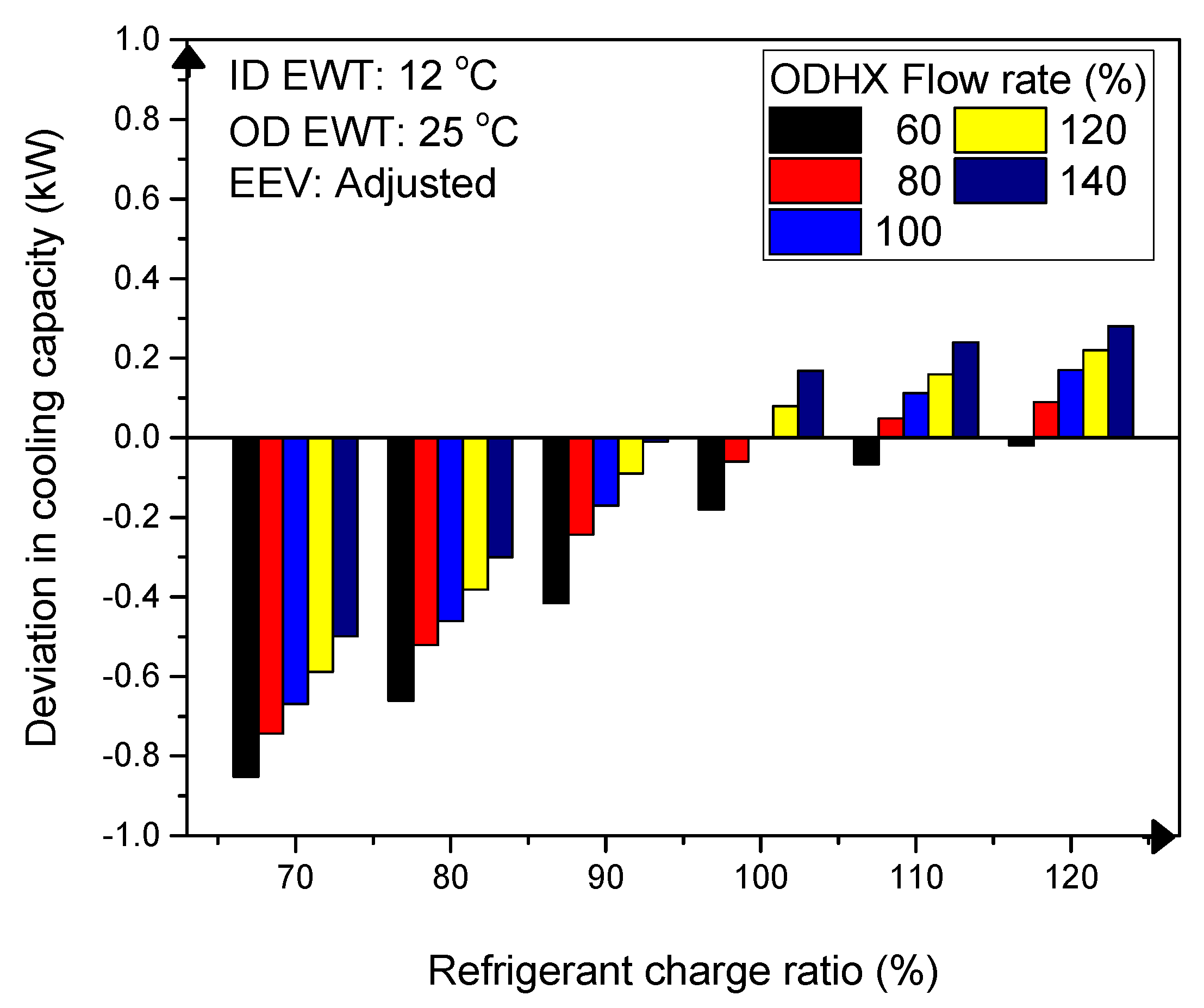
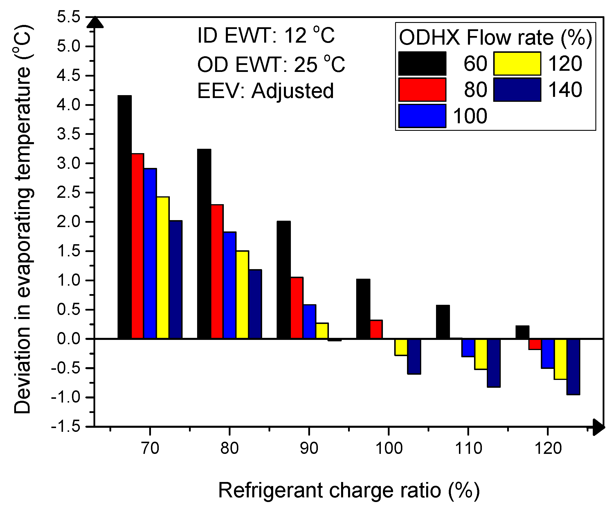
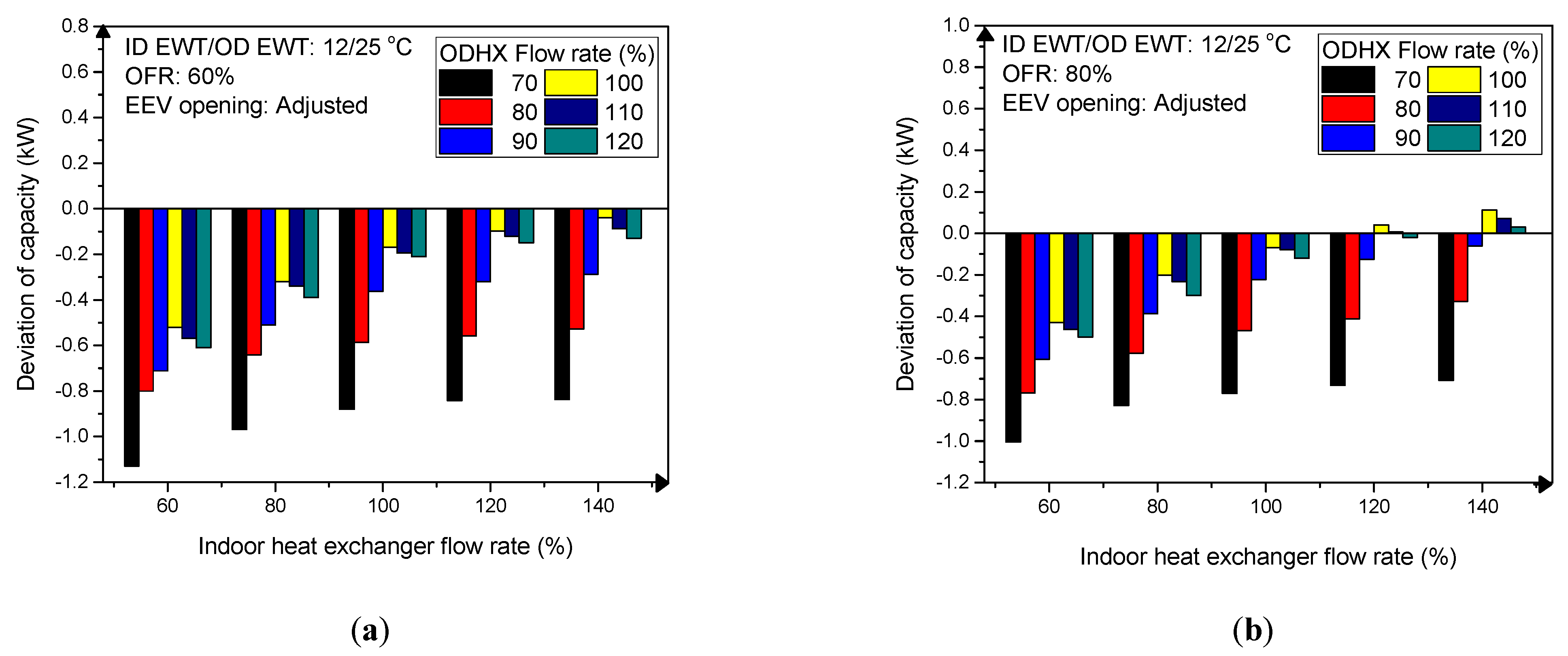
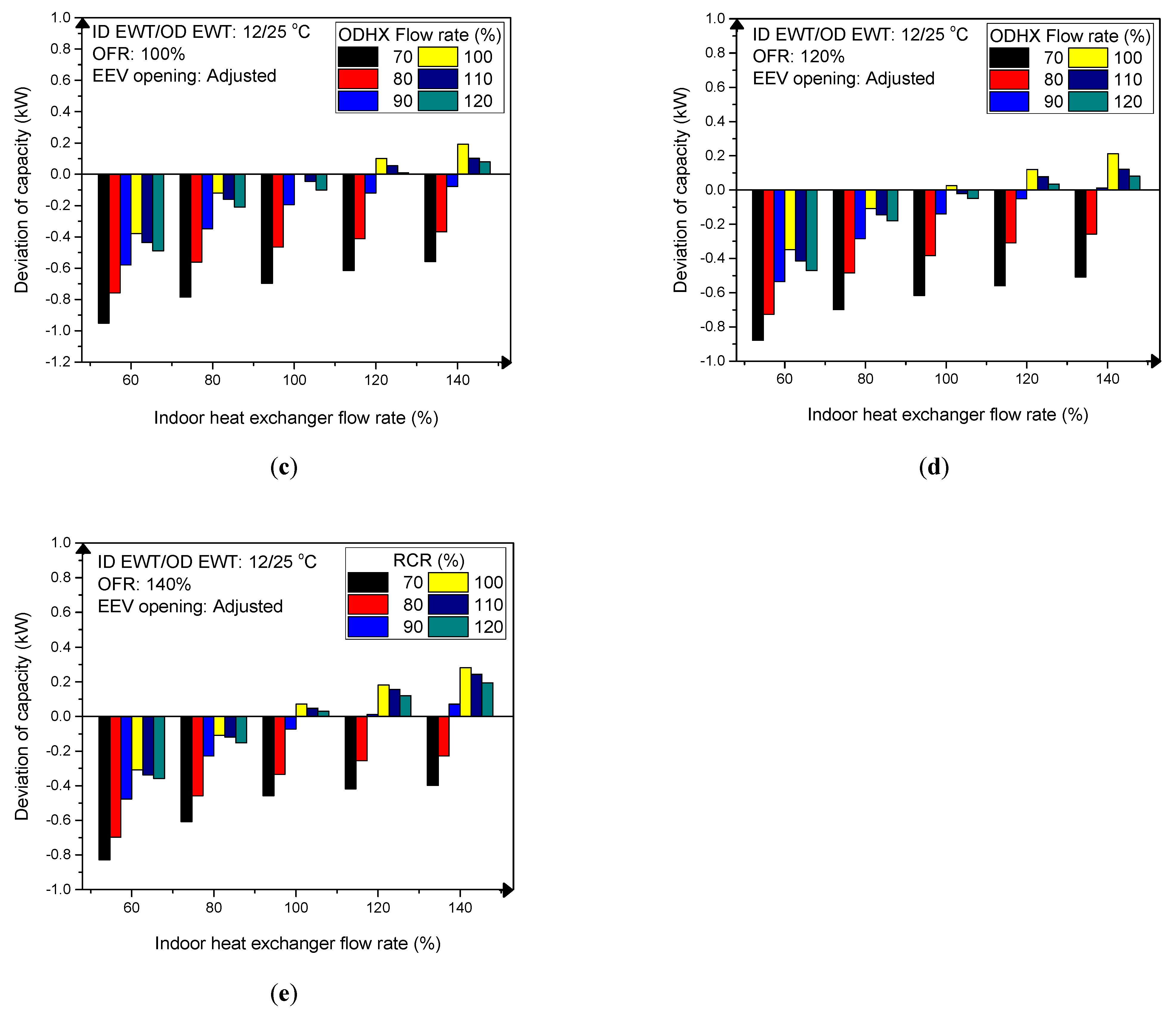
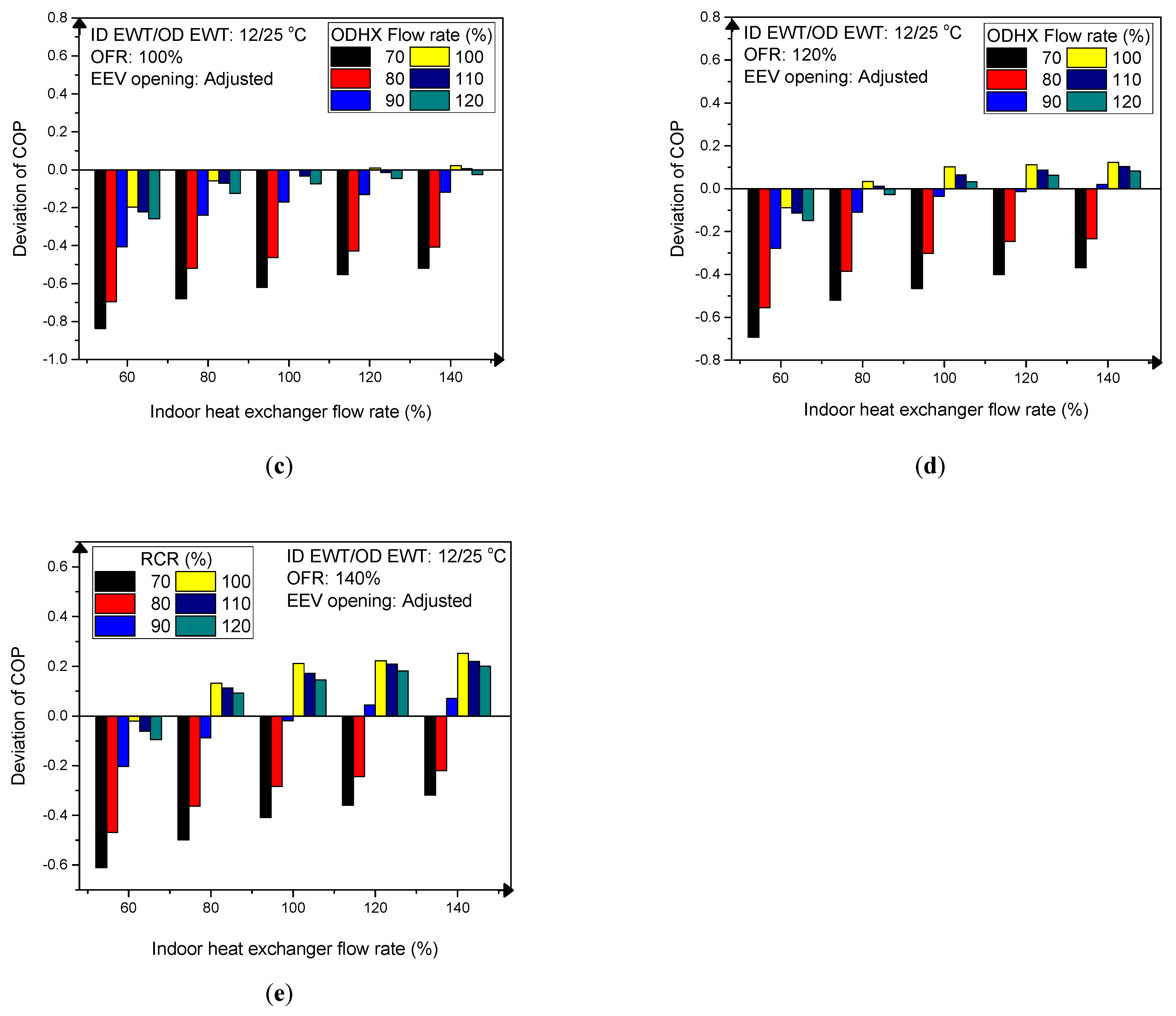
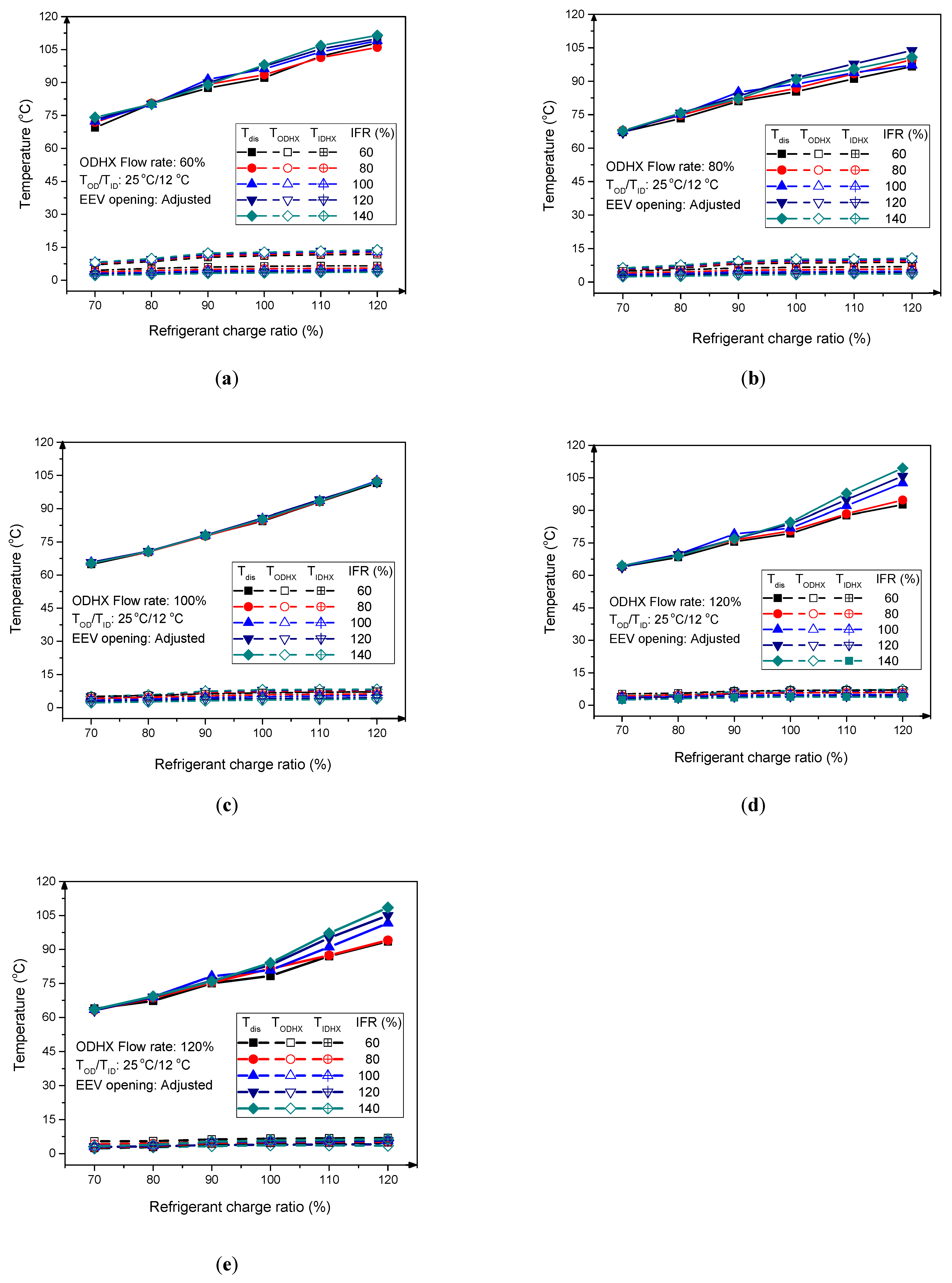
3.1.2. Simultaneous Faults in the Refrigerant Charge and Secondary Fluid Flow Rate of Outdoor Heat Exchanger

Faults in the refrigerant charge and the flow rate of the secondary fluid in the outdoor heat exchanger (OFRF) can exist simultaneously in a heat pump as refrigerant leak and reduced ODHX secondary fluid flow rate (SFFR), refrigerant leak and increased ODHX SFFR, refrigerant overcharge and reduced ODHX SFFR and refrigerant overcharge and increased ODHX SFFR. Figure 5 and Figure 6, respectively, show deviations in the capacity and COP of the heat pump unit in respect to refrigerant charge ratio and ODHX SFFR fault (OFRF). Cooling capacity decreased at all simultaneous refrigerant leakage and reduced ODHX SFFR faults due to increase in evaporating temperature as presented in Figure 7. Refrigerant charge amount directly affects the evaporating temperature; this implies that refrigerant leak greatly affected the cooling capacity and reduced ODHX SFFR. COP of the heat pump also reduced at all simultaneous refrigerant leakage and reduced ODHX SFFR faults because of the reduction in capacity. Furthermore, the cooling capacity decreased at all simultaneous refrigerant leaks and increased ODHX SFFR faults while COP decreased at increased ODHX SFFR and refrigerant leak faults above 10% of the reference value. For simultaneous refrigerant overcharge and reduced ODHX SFFR faults, the cooling capacity remained almost constant while COP decreased. However, cooling capacity and COP increased at refrigerant overcharge and increased ODHX SFFR faults. Regarding simultaneous refrigerant charge and ODHX secondary fluid flow rate faults, refrigerant charge faults greatly affected the cooling capacity than fault in flow rate of the secondary fluid of the ODHX because they significantly affected the subcooling and evaporating temperature; while ODHX SFFR faults had a significant effect on the COP because they greatly affected the condensing pressure and the heat pump’s power consumption.

3.1.3. Simultaneous Faults in the Refrigerant Charge and Secondary Fluid Flow rate of Outdoor Heat Exchanger and Indoor Heat Exchanger

Refrigerant charge fault, and faults in the flow rate of secondary fluid of the IDHX (IFRF) and ODHX (OFRF) can occur simultaneously in a heat pump unit. In this case, there will be a combination of refrigerant undercharge and overcharge occurring simultaneously with either reduced IFRF, increased IFRF, reduced OFRF or increased OFRF. The probable simultaneous faults that may exist and their consequences on the heat pump’s performance are listed in Table 3. Refrigerant overcharge, reduced IFRF and increased OFRF is referred to as simultaneous fault one (SF1). Refrigerant overcharge, reduced IFRF and reduced OFRF is referred to as simultaneous fault two (SF2). Refrigerant overcharge, increased IFRF and increased OFRF is referred to as simultaneous fault three (SF3). Refrigerant overcharge, increased IFRF and reduced OFRF is referred to as simultaneous fault four (SF4). Refrigerant undercharge, reduced IFRF and increased OFRF is referred to as simultaneous fault five (SF5). Refrigerant undercharge, reduced IFRF and reduced OFRF is referred to as simultaneous fault six (SF6). Refrigerant undercharge, increased IFRF and increased OFRF is referred to as simultaneous fault seven (SF7). Refrigerant undercharge, increased IFRF and reduced OFRF is referred to as simultaneous fault eight (SF8). The capacity and COP were greatly affected by the simultaneous occurrence of all three faults as presented in Figure 8 and Figure 9, respectively. The cooling capacity decreased with SF1, SF2, SF4, SF5, SF6 and SF8 but increased with SF3. However, in SF7, cooling capacity decreased at refrigerant undercharge conditions below 80% but increased at refrigerant undercharge conditions higher than 80%. Similarly, COP decreased at SF2, SF4, SF5, SF6 and SF8 conditions due to the combined effect of refrigerant overcharge, reduced IFRF and reduced OFRF, refrigerant overcharge and reduced OFRF, refrigerant undercharge and reduced IFRF, refrigerant undercharge, reduced IFRF and OFRF, refrigerant undercharge and reduced OFRF, respectively. COP decreased at SF3 due to increased IFRF and increased OFRF. However, COP showed an increasing and decreasing effect at SF1 and SF7. At SF1 conditions, COP decreased at all conditions except IFRF between 80% and 100%, while COP decreased at all conditions at SF7, except refrigerant charge ratio between 90% and 100%.
The simultaneous occurrence of all three faults greatly affected the heat pump’s performance than the simultaneous occurrence of two faults. For simultaneous IFRF and refrigerant charge faults at 60% IFRF and 70% refrigerant charge ratio (RCR), capacity and COP, respectively, decreased by 30.5% and 24.3%. However, at 60% IFRF, 70% RCR and 80% OFRF, capacity and COP reduced by 32.2% and 28.2%, respectively. The capacity and COP continued to decrease by 36.2% and 35.9%, respectively, at 60% IFRF, 70% RCR and 60% OFRF. Given simultaneous OFRF and refrigerant charge faults at 60% OFRF and 70% RCR, capacity and COP reduced by 28.2% and 30.9%, respectively. Nonetheless, at 60% OFRF, 70% RCR and 80% IFRF, capacity and COP reduced by 31.0% and 32.6%, respectively. Furthermore, at 60% IFRF, 70% RCR and 60% OFRF, capacity and COP reduced by 36.2% and 35.9%, respectively.

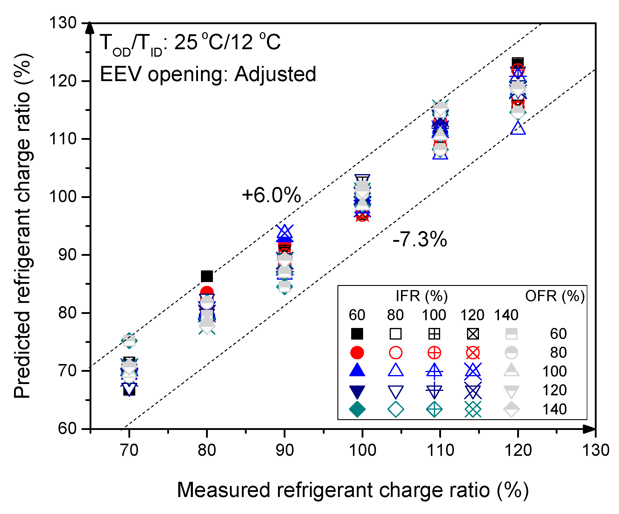
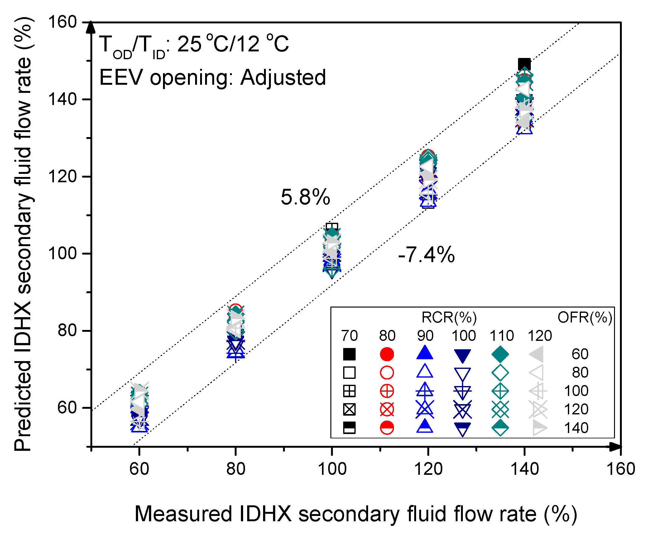
3.2. Development of Fault Detection and Diagnosis Algorithm

This study has shown that capacity and COP of the heat pump greatly deteriorates as intensity of faults increases. It is therefore important to diagnose and detect faults in their early stages to prevent greater damage to the heat pump’s performance. To achieve this, results discussed in this study were used to develop an FDD algorithm, using multiple linear regression, that can detect and diagnose simultaneous refrigerant charge fault and IFRF, simultaneous refrigerant charge fault and OFRF and simultaneous refrigerant charge fault, IFRF and OFRF of the heat pump studied.
According to Boahen et al. [24] and Boahen et al. [31], the compressor discharge temperature, brine temperature difference in the IDHX and ODHX have direct relations with the refrigerant charge fault, IFRF and OFRF, respectively. As a result that these operating parameters can be easily measured using temperature sensors when operating the heat pump, they were selected as independent variables for the FDD algorithm.
The effect of refrigerant charge fault, IFRF and OFRF on compressor discharge temperature, and brine temperature difference in the IDHX and ODHX at different OD EWT is as shown in Figure 10. The FDD algorithm was modelled as a polynomial of 2nd order because of the nature of the curves relating the faults and their corresponding heat pump operating parameters. As shown in Figure 10, the compressor discharge temperature, temperature difference across the indoor heat exchanger and temperature difference across the outdoor heat exchanger show a linear relationship with the refrigerant charge and secondary fluid flow rate faults at 60% and 80% ODHX flow rate. However, from 100% outdoor heat exchanger secondary fluid flow rate, the compressor discharge temperature showed some deviation from linearity. Therefore, to minimize the error margin, a second order polynomial was selected to develop the FDD algorithm. The FDD algorithm is presented in Equation (1), where P is refrigerant charge ratio (RCR), flow rate of the secondary fluid of the outdoor heat exchanger (OFR) or flow rate of the secondary fluid of the indoor heat exchanger (IFR), T I H X is temperature difference of the secondary fluid across the IDHX, T O H X is temperature difference of brine in outdoor heat exchanger, T d i s is compressor discharge temperature while a, b, c, d, e, f, g, h, i are constants that have coefficients as shown in Table 4.
To use the correlation, the outdoor entering water temperature, compressor discharge temperature and temperature difference of the secondary fluid in the IDHX of the heat pump are measured with temperature sensors. The measured data are put into Equation (4), together with the coefficients in Table 4 for RCR correlation, IFR correlation and OFRF correlation to simultaneously determine the refrigerant charge ratio, brine flow rate in the IDHX and ODHX, respectively. The developed correlation was tested by predicting the experimental data used in this study. The correlation accurately predicted the simultaneous refrigerant charge ratio, IFRF and OFRF within an error threshold of ±7.3%, ±7.4% and ±7.7 as shown in Figure 11, Figure 12 and Figure 13, respectively. Figure 14 shows a block diagram of the FDD algorithm for the simultaneous refrigerant charge and flow rate faults discussed in this study. The proposed algorithm is applied when the heat pump is operating at steady state.
P = a + b T I H X + c T I H X 2 + d T O H X + e T O H X 2 + f T d i s + g T d i s 2 + h T I H X T O H X + i T I H X T d i s + j T O H X T d i s

4. Conclusions

In this work, the effects of simultaneous faults in the refrigerant charge and flow rate of the secondary fluid on the performance of a heat pump unit operated in the summer season was investigated. An FDD algorithm was developed for the simultaneous faults in the refrigerant charge amount and flow rate of secondary fluid in the outdoor heat exchanger (OFRF) and indoor heat exchanger (IFRF) using multiple regression analysis. The study concludes as follows:
  • Three faults occurring simultaneously greatly affect the heat pump’s performance compared to the occurrence of two simultaneously combined faults. At 70% refrigerant charge ratio (RCR), 60% IFRF and 60% OFRF, capacity and COP of the heat pump unit decreased, respectively, by 5.7% and 11.6% more than at 70% RCR and 60% IFRF. Furthermore, the heat pump’s capacity and COP decreased, respectively, by 8% and 5.9% at 70% RCR, 60% IFRF and 60% OFRF more than at 70% RCR and 60% OFRF.
  • An FDD algorithm was developed to detect the simultaneous faults using multiple linear regression. The parameters used in the algorithm include discharge temperature of the compressor and the temperature difference of the secondary fluid across the IDHX and ODHX. The developed algorithm was able to detect simultaneous refrigerant charge fault and IFRF, simultaneous refrigerant charge fault and OFRF and simultaneous refrigerant charge fault, IFRF and OFRF within error thresholds of ±7.3%, ±7.6% and ±7.7%, respectively.
  • The proposed FDD model uses temperature sensors to detect and diagnose faults. This method is cheap and simple to use, compared to other FDD models that use thermal imaging models and quantitative model-based methods that demand complex mathematical models of the systems. Thermal imagining is fast, efficient and safe; however, the initial cost of purchasing thermal imaging cameras is high with low accuracy for temperature measurement due to different emissive properties of surfaces. Moreover, thermal imaging FDD methodologies are faster than the proposed methodology. Future studies will focus on developing FDD algorithms for simultaneous refrigerant charge and secondary fluid flow rate faults for heat pumps operating with variable speed compressors.

Author Contributions

S.B. and J.M.C. analysed the data and prepared the manuscript. K.M. and S.K.A. performed the experiment. K.H.L. reviewed the test results and the paper. All authors have read and agreed to the published version of the manuscript.

Funding

This work was sponsored by the Korean government (MSIT) [No. 2019R1A2C2087157].

Data Availability Statement

The data presented in this study are available on request from the corresponding author. The data are not publicly available due to on-going work.

Acknowledgments

This research was assisted by the National Research Foundation of Korea (NRF) grant funded by the Korea government (MSIT) (No. 2019R1A2C2087157, Artificial neutral network-based optimized operating model of building HVAC systems control parameters for improved energy efficiency and reduced operating cost).

Conflicts of Interest

Authors have no conflict of interest.

Nomenclature

COPCoefficient of performance
CpSpecific heat capacity of water [kJ/kgK]
EEVElectronic expansion valve
FDDFault detection and diagnosis
HVACHeating, Ventilation and Air Conditioning
HXHeat exchanger
IFRFIndoor heat exchanger secondary fluid flow rate fault
LPMSecondary fluid flow rate [LPM]
LWTLeaving water temperature [ ° C ]
OD EWTOutdoor heat exchanger entering water temperature [ ° C ]
ODHXOutdoor heat exchanger
OFRFOutdoor heat exchanger secondary fluid flow rate fault
QCapacity [kW]
RCRRefrigerant charge ratio
RTDResistance temperature detector
SFFRSecondary fluid flow rate
TdisDischarge temperature of compressor [ ° C ]
UUncertainty
WPower consumption [kW]
xVariable nominal value
ρ Density of water [kg/m3]

References

  1. Zhang, Z.; Dong, X.; Ren, Z.; Lai, T.; Hou, Y. Influence of refrigerant charge amount and EEV opening on the performance of a transcritical CO2 heat pump water heater. Energies 2017, 10, 1521. [Google Scholar] [CrossRef] [Green Version]
  2. Khan, I.; Capozzoli, A.; Corgnati, S.P.; Cerquitelli, T. Fault detection analysis of building energy consumption using data mining techniques. The mediterranean green energy forum 2013, MGEF-13. Energy Procedia 2013, 42, 557–566. [Google Scholar] [CrossRef] [Green Version]
  3. Li, Y.; O’Neill, Z. A critical review of fault modelling of HVAC systems in buildings. Build. Simul. 2018, 11, 953–957. [Google Scholar] [CrossRef]
  4. Gerrit, B.; Simon, T.; Baranski, M.; Müller, D. Real-world application of machine-learning-based fault detection trained with experimental data. Energy 2020, 198, 117323. [Google Scholar]
  5. Kim, W.; Katipamula, S. A review of fault detection and diagnostics methods for building systems. Sci. Technol. Built Environ. 2018, 24, 3–21. [Google Scholar] [CrossRef]
  6. Abuasbeh, M.; Madani, H. Fault detection and diagnosis for brine to water heat pump systems. In Proceedings of the 12th IEA Heat Pump Conference, Rotterdam, The Netherlands, 15–18 May 2017. [Google Scholar]
  7. Yan, K.; Zhiwei Ji, Z.; Shen, W. Online fault detection methods for chillers combining extended kalman filter and recursive one-class SVM. Neurocomputing 2017, 228, 205–212. [Google Scholar] [CrossRef] [Green Version]
  8. Gálvez, A.; Diez-Olivan, A.; Seneviratne, D.; Galar, D. Fault Detection and RUL Estimation for Railway HVAC Systems Using a Hybrid Model-Based Approach. Sustainability 2021, 13, 6828. [Google Scholar] [CrossRef]
  9. Buffa, S.; Fouladfar, M.H.; Franchini, G.; Lozano Gabarre, I.; Andrés Chicote, M. Advanced control and fault detection strategies for district heating and cooling systems—A review. Appl. Sci. 2021, 11, 455. [Google Scholar] [CrossRef]
  10. Nehasil, O.; Dobiášová, L.; Mazanec, V.; Široký, J. Versatile AHU fault detection—Design, field validation and practical application. Energy Build. 2021, 237, 110781. [Google Scholar] [CrossRef]
  11. Taal, A.; Itard, L. Fault detection and diagnosis for indoor air quality in DCV systems: Application of 4S3F method and effects of DBN probabilities. Build Environ. 2020, 174, 106632. [Google Scholar] [CrossRef]
  12. Granderson, J.; Lin, G.; Harding, A.; Im, P.; Chen, Y. Building fault detection data to aid diagnostic algorithm creation and performance testing. Sci. Data 2020, 7, 1–14. [Google Scholar] [CrossRef]
  13. Park, Y.-J.; Fan, S.-K.S.; Hsu, C.-Y. A review on fault detection and process diagnostics in industrial processes. Processes 2020, 8, 1123. [Google Scholar] [CrossRef]
  14. Shamandi, S.A.; Rasouli Jazi, S. Fault detection in compression refrigeration system with a fixed orifice and rotary compressor. J. Mech. Eng. 2020, 4, 277–286. [Google Scholar]
  15. Zhao, Y.; Wang, S.; Xiao, F. A statistical fault detection and diagnosis method for centrifugal chillers based on exponentially-weighted moving average control charts and support vector regression. Appl. Therm. Eng. 2013, 51, 560–572. [Google Scholar] [CrossRef]
  16. Sellami, A.; Aridhi, E.; Mzoughi, D.; Mami, A. Performance of the Bond Graph Approach for the detection and localization of faults of a refrigerator compartment containing an ice quantity. Int. J. Air Cond. Refrig. 2018, 26, 1850028. [Google Scholar] [CrossRef]
  17. Sun, J.; Im, P.; Bae, Y.; Munk, J.; Kuruganti, T.; Fricke, B. Dataset of low global warming potential refrigerant refrigeration system for fault detection and diagnostics. Sci. Data 2021, 8, 144. [Google Scholar]
  18. Li, B.; Cheng, F.; Cai, H.; Zhang, X.; Cai, W. A semi-supervised approach to fault detection and diagnosis for building HVAC systems based on the modified generative adversarial network. Energy Build. 2021, 246, 111044. [Google Scholar] [CrossRef]
  19. Bellanco, I.; Fuentes, E.; Vallès, M.; Salom, J. A review of the fault behavior of heat pumps and measurements, detection and diagnosis methods including virtual sensors. J. Build. Eng. 2021, 39, 102254. [Google Scholar] [CrossRef]
  20. Dudley, S.; Dey, M.; Rana, S. Semi-supervised learning techniques for automated dault detection and diagnosis of HVAC system. In Proceedings of the IEEE International Conference on Tools with Artificial Intelligence (ICTAI-2018), Volos, Greece, 5–7 November 2018. [Google Scholar]
  21. Eom, Y.H.; Yoo, J.W.; Hong, S.B.; Kim, M.S. Refrigerant charge fault detection method of air source heat pump system using convolutional neural network for energy saving. Energy 2019, 187, 115877. [Google Scholar] [CrossRef]
  22. Zhao, X.; Yang, M.; Li, H. Field implementation and evaluation of a decoupling-based fault detection and diagnosis method for chillers. Energy Build. 2014, 72, 419–430. [Google Scholar] [CrossRef]
  23. Han, H.; Gu, B.; Hong, Y.; Kang, J. Automated FDD of multiple-simultaneous faults (MSF) and the application to building chillers. Energy Build. 2011, 43, 2524–2532. [Google Scholar] [CrossRef]
  24. Boahen, S.; Mensah, K.; Nam, Y.; Choi, J.M. Fault detection methodology for secondary fluid flow rate in a heat pump unit. Energies 2020, 13, 2974. [Google Scholar] [CrossRef]
  25. Miyata, S.; Lim, J.; Akashi, Y.; Kuwahara, Y.; Tanaka, K. Fault detection and diagnosis for heat source system using convolutional neural network with imaged faulty behavior data. Sci. Technol. Built Environ. 2020, 26, 52–60. [Google Scholar] [CrossRef] [Green Version]
  26. Mowris, R.J.; Blankenship, A.; Jones, E. Field Measurements of Air Conditioners with and without TXVs. ACEEE Summer Study Proc. 2004, 1, 212–227. [Google Scholar]
  27. Roth, K.; Westphalen, D.; Broderick, J. Residential Central AC Fault Detection & Diagnostics. ASHRAE J. 2019, 48, 96–97. [Google Scholar]
  28. International Standard. ISO 13256-2, 1998. Water-Source Heat Pumps—Testing and Rating for Performance Part 2 Water-to-Water and Brine-to-Water Heat Pumps; ISO: Geneva, Switzerland, 1998. [Google Scholar]
  29. KEMCO. NR GT 101, 2008, Water-to-Water Ground Source Heat Pump; NRGT: Yongin, Korea, 2008. [Google Scholar]
  30. ASHRAE. ASHRAE Guideline 2. Engineering Analysis of Experimental Data; ASHRAE: Atlanta, GA, USA, 1986. [Google Scholar]
  31. Boahen, S.; Lee, K.H.; Choi, J.M. Refrigerant charge fault detection and diagnosis algorithm for water-to-water heat pump unit. Energies 2019, 12, 545. [Google Scholar] [CrossRef] [Green Version]
Figure 1. Schematic diagram of the heat pump.
Energies 14 03877 g001
Figure 2. Photograph of refrigerant flow loop, secondary fluid flow loop and data acquisition system of heat pump.
Energies 14 03877 g002
Figure 3. Deviation in reference capacity according to refrigerant charge and indoor heat exchanger flow rate combined faults.
Energies 14 03877 g003
Figure 4. Deviation in COP according to refrigerant charge and indoor heat exchanger flow rate combined faults.
Energies 14 03877 g004
Figure 5. Change in capacity according to refrigerant charge and outdoor heat exchanger flow rate combined faults.
Energies 14 03877 g005
Figure 6. Change in COP with refrigerant charge and outdoor heat exchanger flow rate combined faults.
Energies 14 03877 g006
Figure 7. Change in evaporating temperature according to refrigerant charge and outdoor heat exchanger flow rate faults.
Energies 14 03877 g007
Figure 8. Change in cooling capacity according to refrigerant charge and flow rate of secondary fluid in indoor and outdoor heat exchanger of (a) 60%, (b) 80%, (c) 100%, (d) 120% and (e) 140%.
Energies 14 03877 g008aEnergies 14 03877 g008b
Figure 9. Change in COP according to refrigerant charge ratio and flow rate of secondary fluid in indoor and outdoor heat exchanger of (a) 60%, (b) 80%, (c) 100%, (d) 120% and (e) 140%.
Energies 14 03877 g009aEnergies 14 03877 g009b
Figure 10. Variation of compressor discharge temperature, temperature difference of outdoor heat exchanger secondary fluid, temperature difference of indoor heat exchanger secondary fluid according to refrigerant charge ratio and indoor heat exchanger secondary fluid flow rate of (a) 60%, (b) 80%, (c) 100%, (d) 120% and (e) 140%.
Energies 14 03877 g010
Figure 11. Error threshold of refrigerant charge for simultaneous refrigerant charge fault, indoor heat exchanger flow rate fault and outdoor heat exchanger flow rate fault.
Energies 14 03877 g011
Figure 12. Error threshold of indoor heat exchanger secondary fluid flow rate for simultaneous refrigerant charge fault, indoor heat exchanger flow rate fault and outdoor heat exchanger flow rate fault.
Energies 14 03877 g012
Figure 13. Error threshold of outdoor heat exchanger secondary fluid flow rate for simultaneous refrigerant charge fault, indoor heat exchanger flow rate fault and outdoor heat exchanger flow rate fault.
Energies 14 03877 g013
Figure 14. FDD algorithm for simultaneous refrigerant charge and secondary fluid flow rate faults.
Energies 14 03877 g014
Table 1. Experimental conditions.
VariableBase ConditionTest Range
Mode of operationCoolingCooling
Type of refrigerantR410AR410A
Refrigerant charge amount (kg)4.74.7
Ratio of refrigerant charge amount (%)10070, 80, 90, 100, 110, 120
Indoor heat exchanger EWT ( ° C ) 1212
Outdoor heat exchanger EWT ( ° C ) 2520, 25, 30, 35
Secondary fluid flow rate of ODHX (LPM)860, 80, 100, 120, 140
Secondary fluid flow rate of IDHX (LPM)860, 80, 100, 120, 140
Table 2. Sensors and their accuracies.
SensorAccuracy
Pressure transducer±0.5%
T-Type thermocouple ±0.2 ° C
Power meter±0.5% of reading
Mass flow meter±0.5% of reading
Volumetric flowmeter±2% of reading
RTD sensor±0.15 ° C
Table 3. Simultaneous faults in refrigerant charge and flow rate of secondary fluid of outdoor heat exchanger and indoor heat exchanger.
SFRefrigerant Charge FaultFault in the Flow Rate of the IDHX Secondary FluidFault in the Flow Rate of the ODHX Secondary FluidCooling CapacityCOP
1.Refrigerant overchargeReduced IFRFIncreased OFRF Energies 14 03877 i001 Energies 14 03877 i002
2.Refrigerant overchargeReduced IFRFReduced OFRF Energies 14 03877 i001 Energies 14 03877 i001
3.Refrigerant overchargeIncreased IFRFIncreased OFRF Energies 14 03877 i003 Energies 14 03877 i003
4.Refrigerant overchargeIncreased IFRFReduced OFRF Energies 14 03877 i001 Energies 14 03877 i001
5.Refrigerant underchargeReduced IFRFIncreased OFRF Energies 14 03877 i001 Energies 14 03877 i001
6.Refrigerant underchargeReduced IFRFReduced OFRF Energies 14 03877 i001 Energies 14 03877 i001
7.Refrigerant underchargeIncreased IFRFIncreased OFRF Energies 14 03877 i002 Energies 14 03877 i002
8.Refrigerant underchargeIncreased IFRFReduced OFRF Energies 14 03877 i001 Energies 14 03877 i001
Table 4. Coefficients of simultaneous RCR, IFRF and OFRF FDD correlations.
CoefficientsRCR CorrelationIFROFR
a−152.2−281.9−372.8
b−14.43−31.63−49.67
c−0.5533−0.43960.9043
d−4.863−45.12−2.046
e0.21563.51981070.6293
f5.98714.4215.48
g−0.0373−0.08216−0.08193
h−0.25630.58730.969
i0.24380.34730.1717
j0.05946−0.2359−0.191
Publisher’s Note: MDPI stays neutral with regard to jurisdictional claims in published maps and institutional affiliations.

