
Advanced Concrete Steam Accumulation Tanks for Energy Storage for Solar Thermal Electricity

 ,
,  and
and 
Abstract
:1. Introduction
2. Conceptual Design
- Yield strength (MPa): 890 MPa
- Tensile strength: 940–1100 MPa
- High Strength Steel (RQT 901®).
3. Materials and Methods
3.1. Materials
- Thermal conductivity: λ = 0.2 W/m·K.
- Compressive strength (90 days): Rc (90 d) = 20 MPa
- Compressive strength (28 days): Rc (28 d) = 100 MPa
- Self-compacting properties, as stated on EHE Spanish Concrete Instruction (annex 17, where materials description, calculation specifications and fabrication properties are established) [9].
- Refractory concrete: HL-30/B/10
- High performance concrete: HAR-100/AC/8
3.2. Lab-Scale Concrete Development
3.2.1. Refractory Concrete Fabrication
- (a)
- measure the moisture of the lightweight aggregate and adjust the amount of water and aggregate with respect to the final composition;
- (b)
- adding, in the order described (the water, the superplasticizer additive, the cement and the fly ash to a mixing device);
- (c)
- adding the fine aggregate or sand to the mixture obtained in (b); and
- (d)
- adding the coarse aggregate or gravel to the mixture obtained in (c).
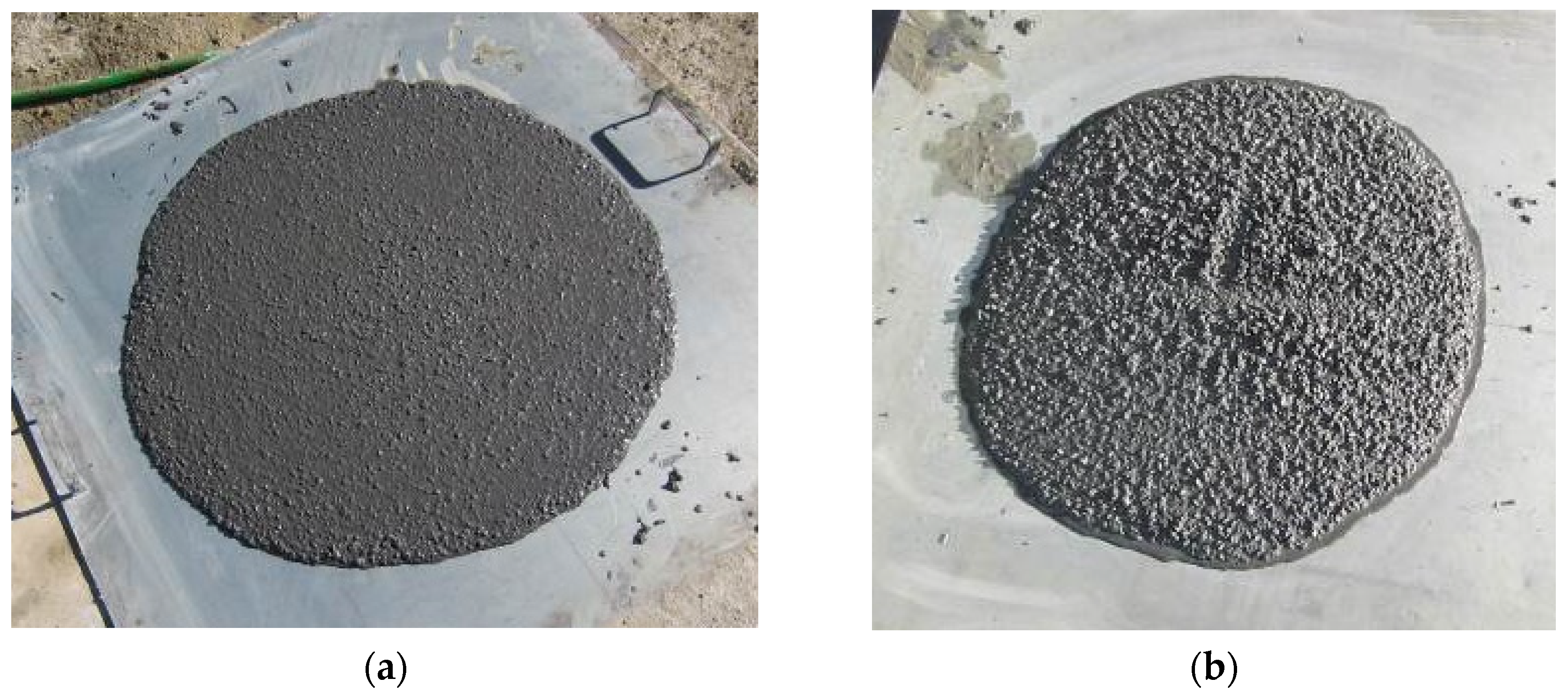
- Regarding the characterization in fresh state of the refractory concrete, the settlement test or slump Abrams cone test is carried out, according to the specifications of the UNE EN 12350-2:2006 standard [26]. This test is used to determine the consistency of the mixture at the time of pouring the concrete. It also checks the homogeneity of the concrete through the segregation of the mixture.
- Regarding the characterization in the hardened state of the refractory concrete, tests of resistance to compression of cylindrical specimens are carried out, according to the UNE 12390-3:2001 standard [27].
- Indirect traction resistance tests are also carried out on cylindrical specimens UNE 12390-6:2010 [28] as well as thermal conductivity. For thermal conductivity tests, conductivity measurements are made both at room temperature (method A) according to the application of the UNE EN 12667:2002 standard [29], and at 150 °C and 250 °C (method B).
3.2.2. High-Performance Concrete Fabrication
3.3. Analytical Methods
3.4. Scaling-Up Concrete Preparation
- Measurement of aggregates moisture to monitor actual w/c ratio.
- Correction of dosage searching for the referent w/c ratio, in each case, for the concrete volume required.
- Addition of aggregates (fine and coarse fractions), discarding first quantities from hopper due to excessive moisture at the bottom of said element.
- Addition of fibers and fines.
- Weighing 2/3 of water quantity to add to the retarder admixtures, reserving the remaining 33.33% to add later.
- Addition of cement.
- Addition of the remaining 1/3 of water with the super-plasticizer additive
- Mix for several minutes and visual inspection.
- Transfer to construction site with truck hopper beating at maximum power (expected workability time 50 to 60 min).
- In case of non-self-compacting mixture on construction site, one re-dosage is allowed with a mix of 10 L of water with 1 L of super-plasticizer (additive supplier suggestion based on similar experiences on-field).
- Measurement of aggregates moisture to monitor actual w/c ratio.
- Correction of dosage searching for the referent w/c ratio, in each case, for the concrete volume required.
- After correction, weighing 90% of water quantity and reserving the remaining 10% to add at the end.
- Addition of super-plasticizer.
- Addition of cement and additional components at the same time to save pouring time (adding directly to the truck).
- Addition of fine aggregates fraction.
- Ascending movement of charging truck hopper three times to observe mixture and pull remainder material of hopper surfaces, at maximum speed (for 10 min). Mixture should have fluid appearance but be viscous.
- Addition of coarse aggregates fraction.
- Mix for several minutes.
- Realization of workability test. Expected consistency is soft. If Abrams cone measured is lower, ration water in 20 kg-units until the effective w/c ratio searched, checking that workability is that which is required.
- Transfer to construction site with truck hopper beating at maximum power (expected workability time 30 to 40 min).
3.5. Insulating Refractory Concrete Thermal Cycling
4. Results and Discussion
4.1. Results of Lab Tests
4.1.1. High-Strength Self-Compacting Concrete Development
- Cement: For its use in HSSCC, cement must have an adjusted composition and fine grains, presenting high strength and, in turn, allowing good mixture workability. Cement fine size can be adjusted through grinding. The high specific surface area reached through the grinding process also benefits concrete self-compacting. Specifically, Portland CEM I cement of the highest resistant category (52.5 R) is appropriate, as well as any cement with high resistance additions, such as silica fume.
- Aggregates: In HSSCC fabrication the selection of aggregates must be more rigorous than in conventional concretes focusing on their good adherence with cement paste and their mechanical strength, which must exceed the target strength of the concrete to be formulated. Coarse aggregate tends to be smaller than conventional concrete aggregates, generally lower than 20 mm; thus, a better flowability, better particles cohesion and higher strength are reached. Regarding fine aggregates, there is almost an absence of fines, which is solved by the large quantity of cement and additives [41].
- Filler: The employment of mineral filler allows the workability of the concrete mixture, especially needed in self-compacting HSSCC [50]. Mineral fillers, which are fine particles whose largest part passes through a 63 µm sieve during sifting, can be considered as aggregates since they are obtained by grinding the same aggregate materials. Their selection must be made paying attention to their grading distribution, assuring compatibility with the rest of the concrete components by means of trial batches.
- Additives: In HSSCC it is indispensable to use fine additives, normally those with strong pozzolanic effect, due to two main reasons: (i) they add fines to get a good self-compacting behavior and (ii) they react with the resultant portlandite from cement hydration contributing to an important increase in concrete strength. Therefore, it is essential that additions present elevated fineness, high activity, great compatibility with other components and uniformity in their production [51]. Some facilitate self-compacting property due to their spherical shape, optimizing the packing of solid particles during fresh state, and helping improve the concrete strength by reacting with portlandite (pozzolanic reaction from cement hydration) [10,52] like fly ashes. Silica fume, or micro silica, is a by-product obtained from electric arc furnaces of silicon production and ferro-silicon alloys fabrication. It is composed of 90–95% amorphous silicon (SiO2) and other minority components (Fe2O3, CaO, MgO, etc.). Silica fume particles have a large specific surface (around 20 m2/g) [10]. Adding silica fumes requires high water quantity due to its elevated specific surface area, but it adds improvements to fresh concrete properties such as decreasing segregation and exudation. Similarly to fly ashes, but more intensively, it contributes to a concrete strength increase due to its nature and a filler effect derived from its elevated specific surface, creating a paste–aggregate transition zone more compact than concretes without this type of addition [11]. Metakaolin is another pozzolanic material obtained by kaolinite calcination and it is mainly composed of silica (SiO2) and alumina (Al2O3), although it also has other minority oxides such as Fe2O3, CaO or MgO. Once again due to its pozzolanic reactivity and filler effect, metakaolin facilitates concrete elevated strengths. It also adds a higher durability by increasing concrete sulphate resistance and by complicating chloride diffusion, because concrete capillary porosity decreases [37].
- Fibers: Fibers are elements of short length and small section added to concrete. They can be classified according to their function in two large groups: (i) structural function, by providing post-cracking resistance to bulk concrete, and (ii) non-structural function, although improving concrete behavior against fire, shrink, wear, impact, etc. In the development of this high-strength concrete, polypropylene concrete fibers with non-structural function are used.
- Admixtures: Substances added in small quantities into concretes (less than 5% regarding cement mass) to modify properties, characteristics or behaviors [9]. These are chemical formulations, essential to obtain high-performance concretes. Super-plasticizers are the main used admixtures for HSSCC. However, there are other admixtures that can be used to complement super-plasticizers, such as viscosity modulators, setting retardant, etc. Super-plasticizers allow large reductions of water quantity in the mixture without losing concrete flowability. In the past, the most commonly used super-plasticizers were melanin or naphthalene sulfonate and modified lignosulphonates, although nowadays the most common are based on polycarboxylate chains. These types of substance disperse cement particles, avoiding their flocculation since they are adsorbed over cement grains. By repulsive electrostatic interactions they unlock occluded water, making it available for fluidizing mix fine grains, increasing the workability of concrete. In addition to these interactions, polycarboxylate admixtures also apply a steric effect keeping separated cement grains with more efficiency and allowing enormous reductions in water dosage [11]. It is important to check compatibility between super-plasticizers, cement and selected fines, above all when the objective is to obtain low water/concrete (w/c) ratios, due to possible segregation problems or setting alterations. Retarder admixtures increase concrete setting and/or hardening times, complicating at least at an initial stage the hydration of anhydrous components of cement. Their chemical composition is very variable, with sugars, lignosulphonates, zinc salts, borates, etc. [39]. They can act in two different ways, depending on their nature: (i) by facilitating calcium sulphate solubility that is a natural setting retarder, or (ii) by forming calcium salts to cover cement particles surfaces, thus retarding their hydration. Their use is convenient when cement quickly hydrates, because of its own nature or elevated temperature or due to the use of efficient super-plasticizers, being incompatible with construction requirements.
4.1.2. Insulating Refractory Concrete Development
- Target density achievement: fresh state, hardened state after 24 h, hardened state at different ages, hardened state of dry simple (24 h, 45 °C), and hardened state after thermal ageing at 300 °C.
- Thermal resistance assessment.
- Compressive strength assessment.
- Behavior assessment after thermal ageing.
- Conclusions, feedback, and formulation modification.
4.2. Results of Scaling Up Tests
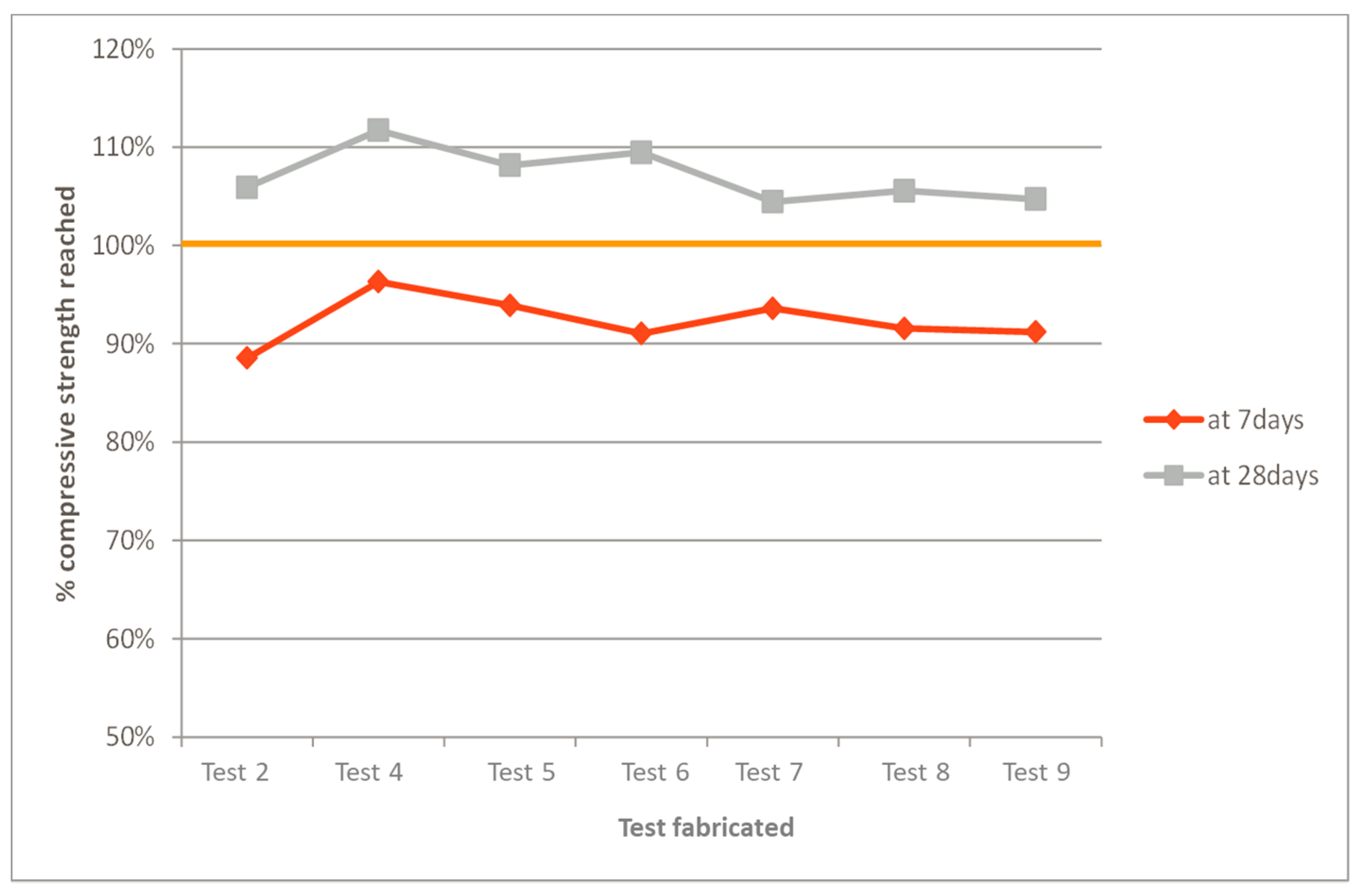
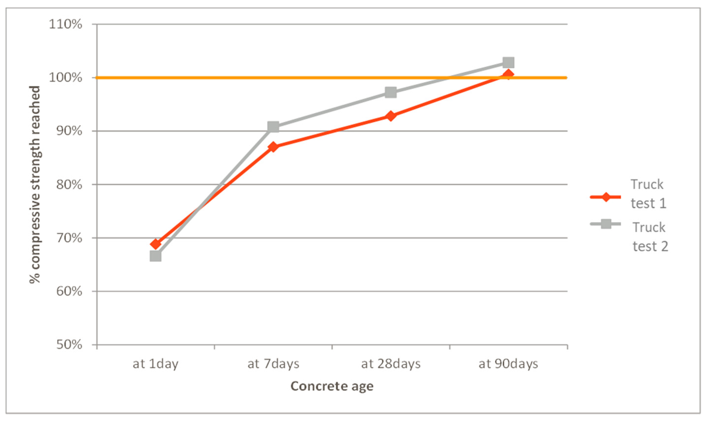
4.2.1. High-Strength Self-Compacting Concrete Fabrication
4.2.2. Insulating Refractory Concrete Fabrication
4.2.3. Thermal Cycling of the Insulating Refractory Concrete
5. Conclusions
- The moisture of aggregates and additions is the main factor found during this concrete fabrication. This point is directly related to the storage conditions of the raw materials. It is shown that external storage could create an excess of moisture in the aggregates and additions that could cause changes in the hydration process of concrete fabrication. This fact triggers a dosage correction that might be inaccurate if, in following concreting processes, the storing conditions are different, when water absorption increases and, therefore, causes a drier concrete mix that does not meet the expected workability requirements.
- Effective w/c ratio is the key control parameter for the success of insulating refractory concrete fabrication, supported by workability tests with the Abrams cone method. A suitable and accurate previous determination, as well as a constant control during concrete fabrication, permits the achievement of the target resistance and thermal requirements. The success of this insulating refractory concrete is based on a referent effective w/c ratio establishing limits for the fabrication process. Besides, workability verification presents value of 20 cm in the Abrams cone for acceptance of the concrete mixture transfer.
- Aggregates and their physical properties represent the second most important factor to rigorously control the properties of insulating refractory concrete. The selection of such special aggregate, expanded clay, determines that porosity and absorption grade are critical points to match specified requirements in all the mixtures fabricated. It is essential to previously control aggregate porosity and absorption in every batch, since grains absorb a fraction of the dosage water during fabrication, reducing the planned amount of water to be combined with the cementitious products. This fact has a negative effect if the dosage is not previously corrected, leading to structurally weak and non-uniform concrete.
- The instantaneous moisture of aggregates is identified as a key parameter. Dosage correction by the absorbed water is directly related to that parameter at the time the compounds are mixed. Due to very high absorption of the selected gravel, pre-saturation of gravel grains is prescribed so that dosage water is not absorbed by aggregates. Regarding sand, the formulation correction is applied by means of the previous measurement of moisture just before the charge of the other component materials. This factor is also linked to the first (effective w/c ratio), creating a control parameter triangle which must be the axis around which concrete is fabricated: w/c, absorption grade and aggregates moisture.
- Finally, ambient temperature is confirmed as the external factor per excellence in concrete fabrication. Moreover, with such high temperatures during this research, this factor becomes critical. It is necessary to minimize temperature affection on concrete with measures such as: (i) previous saturation of aggregates, (ii) protection of mixture fabrication hoppers from direct radiation of sun and (iii) a quick and efficient transfer to construction site to maintain required workability.
Author Contributions
Funding
Data Availability Statement
Acknowledgments
Conflicts of Interest
References
- Liu, M.; Steven Tay, N.H.; Bell, S.; Belusko, M.; Jacob, R.; Will, G.; Saman, W.; Bruno, F. Review on concentrating solar power plants and new developments in high temperature thermal energy storage technologies. Renew. Sustain. Energy Rev. 2016, 53, 1411–1432. [Google Scholar] [CrossRef]
- International Renewable Energy Agency (IRENA). Innovation Outlook: Thermal Energy Storage; International Renewable Energy Agency: Abu Dhabi, United Arab Emirates, 2020. [Google Scholar]
- González-Roubaud, E.; Pérez-Osorio, D.; Prieto, C. Review of commercial thermal energy storage in concentrated solar power plants: Steam vs. molten salts. Renew. Sustain. Energy Rev. 2017, 80, 133–148. [Google Scholar] [CrossRef]
- Pirvaram, A.; Sadrameli, S.M.; Abdolmaleki, L.; Sivaram, A.R.; Karuppasamy, K.; Rajavel, R. Review on phase change materials (PCMs) for cold thermal energy storage applications. Int. J. Refrig. 2017, 35, 984–991. [Google Scholar] [CrossRef]
- Islam, M.T.; Huda, N.; Abdullah, A.B.; Saidur, R. A comprehensive review of state-of-the-art concentrating solar power (CSP) technologies: Current status and research trends. Renew. Sustain. Energy Rev. 2018, 91, 987–1018. [Google Scholar] [CrossRef]
- Stekli, J.; Irwin, L.; Pitchumani, R. Technical Challenges and Opportunities for Concentrating Solar Power with Thermal Energy Storage. J. Therm. Sci. Eng. Appl. 2013, 5. [Google Scholar] [CrossRef]
- Liu, J.; Kong, J.; Kong, X. Shaking table model tests of concrete containment vessel (CCV) for CPR1000 nuclear power plant. Prog. Nucl. Energy 2016, 93, 186–204. [Google Scholar] [CrossRef]
- Afefy, H.M. Seismic Retrofitting of Reinforced-Concrete Coupled Shear Walls: A Review. Pract. Period Struct. Des. Constr. 2020, 25, 03120001. [Google Scholar] [CrossRef]
- De Fomento, M. Instrucción de Hormigón Estructural; EHE-08 2008; Ministerio de Fomenta: Madrid, Spain, 2010.
- Asociación Española de Hormigón Estructural. Monografía M-13 de Ache. In Hormigón Autocompactante: Diseño y Aplicación; Asociación Española de Hormigón Estructural: Madrid, Spain, 2018. [Google Scholar]
- Aitcin, P. High Performance Concrete; CRC Press: London, UK, 1998; Volume 19980236, pp. 1–624. [Google Scholar] [CrossRef]
- Moreno, D.; Zunino, F.; Paul, Á.; Lopez, M. High strength lightweight concrete (HSLC): Challenges when moving from the laboratory to the field. Constr. Build. Mater. 2014, 56, 44–52. [Google Scholar] [CrossRef]
- Al-Jabri, K.S.; Hago, A.W.; Al-Nuaimi, A.S.; Al-Saidy, A.H. Concrete blocks for thermal insulation in hot climate. Cem. Concr. Res. 2005, 35, 1472–1479. [Google Scholar] [CrossRef]
- Salas, J.; Alvarez, M.; Veras, J. Lightweight insulating concretes with rice husk. Int. J. Cem. Compos. Light Concr. 1986, 8, 171–180. [Google Scholar] [CrossRef]
- Chabannes, M.; Bénézet, J.-C.; Clerc, L.; Garcia-Diaz, E. Use of raw rice husk as natural aggregate in a lightweight insulating concrete: An innovative application. Constr. Build. Mater. 2014, 70, 428–438. [Google Scholar] [CrossRef]
- Liu, M.Y.J.; Alengaram, U.J.; Jumaat, M.Z.; Mo, K.H. Evaluation of thermal conductivity, mechanical and transport properties of lightweight aggregate foamed geopolymer concrete. Energy Build. 2014, 72, 238–245. [Google Scholar] [CrossRef]
- Huiskes, D.M.A.; Keulen, A.; Yu, Q.L.; Brouwers, H.J.H. Design and performance evaluation of ultra-lightweight geopolymer concrete. Mater. Des. 2016, 89, 516–526. [Google Scholar] [CrossRef]
- Chen, B.; Liu, N. A novel lightweight concrete-fabrication and its thermal and mechanical properties. Constr. Build. Mater. 2013, 44, 691–698. [Google Scholar] [CrossRef]
- Yu, Q.L.; Spiesz, P.; Brouwers, H.J.H. Ultra-lightweight concrete: Conceptual design and performance evaluation. Cem. Concr. Compos. 2015, 61, 18–28. [Google Scholar] [CrossRef]
- López, M.; Kahn, L.F. Hormigón liviano de alto desempeño—Una comparación entre pérdidas de pretensado reales y estimadas por los códigos de diseño. Rev. Ing. Construcción 2007, 22. [Google Scholar] [CrossRef] [Green Version]
- Ke, Y.; Beaucour, A.L.; Ortola, S.; Dumontet, H.; Cabrillac, R. Influence of volume fraction and characteristics of lightweight aggregates on the mechanical properties of concrete. Constr. Build. Mater. 2009, 23, 2821–2828. [Google Scholar] [CrossRef]
- Dhir, K.; Mays, R.G.C.; Chua, H.C. Lightweight structural concrete with Aglite aggregate: Mix design and properties. Int. J. Cem. Compos. Light Concr. 1984, 6, 249–261. [Google Scholar] [CrossRef]
- Wilson, H.S.; Malhotra, V.M. Development of high strength lightweight concrete for structural applications. Int. J. Cem. Compos. Light Concr. 1988, 10, 79–90. [Google Scholar] [CrossRef]
- Kockal, N.U.; Ozturan, T. Effects of lightweight fly ash aggregate properties on the behavior of lightweight concretes. J. Hazard. Mater. 2010, 179, 954–965. [Google Scholar] [CrossRef] [PubMed]
- Kockal, N.U.; Ozturan, T. Durability of lightweight concretes with lightweight fly ash aggregates. Constr. Build. Mater. 2011, 25, 1430–1438. [Google Scholar] [CrossRef]
- Asociación Española de Normalización y Certificación (AENOR). Testing Fresh Concrete—Part 2: Slump Test 2006; UNE-EN 12350-2:2006; AENOR: Madrid, Spain, 2006. [Google Scholar]
- Asociación Española de Normalización y Certificación (AENOR). Testing Hardened Concrete—Part 3: Compressive Strength of Test Specimens 2001; UNE 12390-3:2001; AENOR: Madrid, Spain, 2001. [Google Scholar]
- Asociación Española de Normalización y Certificación (AENOR). Testing Hardened Concrete—Part 6: Tensile Splitting Strength of Test Specimens 2010; UNE 12390-6:2010; AENOR: Madrid, Spain, 2010. [Google Scholar]
- Asociación Española de Normalización y Certificación (AENOR). Thermal Performance of Building Materials and Products—Determination of Thermal Resistance by Means of Guarded Hot Plate and Heat Flow Meter Methods: Products of High and Medium Thermal Resistance 2002; UNE-EN 12667:2002; AENOR: Madrid, Spain, 2002. [Google Scholar]
- Asociación Española de Normalización y Certificación (AENOR). Testing Fresh Concrete—Part 8: Self-Compacting Concrete—Slump-Flow Test 2020; UNE-EN 12350-8:2020; AENOR: Madrid, Spain, 2020. [Google Scholar]
- Asociación Española de Normalización y Certificación (AENOR). Testing Fresh Concrete—Part 9: Self-Compacting Concrete—V-Funnel Test 2011; UNE-EN 12350-9:2011; AENOR: Madrid, Spain, 2011. [Google Scholar]
- Asociación Española de Normalización y Certificación (AENOR). Testing Fresh Concrete—Part 10: Self-Compacting Concrete—L Box Test 2011; UNE-EN 12350-10:2011; AENOR: Madrid, Spain, 2011. [Google Scholar]
- Asociación Española de Normalización y Certificación (AENOR). Testing Fresh Concrete—Part 12: Self-Compacting Concrete—J-Ring Test 2011; UNE-EN 12350-12:2011; AENOR: Madrid, Spain, 2011. [Google Scholar]
- Okamura, H.; Ozawa, K. Mix design for self-compacting concrete. Concr. Libr. JSCE 1995, 25, 107–120. [Google Scholar]
- De Larrard, F. A method for proportioning high-strength concrete mixtures. Cem. Concr. Aggreg. 1990, 12, 47–52. [Google Scholar] [CrossRef]
- Billberg, P.; Petersson, Ö.; Österberg, T. Full Scale Casting of Bridges with Self-Compacting Concrete. In First International RILEM Symposium on Self-Compacting Concrete; Skarendahl, A., Petersson, O., Eds.; RILEM Publications: Stockholm, Sweden, 1999; pp. 639–650. [Google Scholar]
- Siddique, R.; Klaus, J. Influence of metakaolin on the properties of mortar and concrete: A review. Appl. Clay Sci. 2008, 43, 392–400. [Google Scholar] [CrossRef]
- Domone, P.L.; Jin, J.H.-W.; Chai Ravindra, K.; Dhir Jones, M.R. Optimum Mix Proportioning of Self Compacting Concrete. In Innovation in Concrete Structures: Design and Construction; ASCE Press: Reston, VA, USA, 1999; pp. 277–285. [Google Scholar]
- Rixom, M. Aditivos Para los Hormigones: Composición, Propiedades y Empleo; Editores Asociados: Barcelona, Spain, 1984. [Google Scholar]
- Gettu, R.; Agullo, L. Estado del arte del hormigón autocompactable y su caracterización: Parte II. Cem. Hormigón 2004, 862, 32–55. [Google Scholar]
- American Concrete Institute. 211.4R-08: Guide for Selecting Proportions for High-Strength Concrete Using Portland Cement and Other Cementitious Materials; American Concrete Institute: Farmington Hills, MI, USA, 2008. [Google Scholar]
- Asociación Española de Normalización y Certificación (AENOR). Concrete Tests—Determination of the Modulus of Elasticity in Compression; UNE 83316:1996; AENOR: Madrid, Spain, 1996. [Google Scholar]
- Asociación Española de Normalización y Certificación (AENOR). Products and Systems for the Protection and Repair of Concrete Structures—Test Methods—Determination of Modulus of Elasticity in Compression; UNE-EN 13412:2008; AENOR: Madrid, Spain, 2008. [Google Scholar]
- Asociación Española de Normalización y Certificación (AENOR). Testing Hardened Concrete—Part 7: Density of Hardened Concrete; UNE-EN 12390-7:2001; AENOR: Madrid, Spain, 2001. [Google Scholar]
- American Society for Testing and Materials (ASTM). Standard Test Method for Density, Absorption, and Voids in Hardened Concrete; ASTM C-642/06; ASTM: West Conshohocken, PA, USA, 2006. [Google Scholar]
- Asociación Española de Normalización y Certificación (AENOR). Methods of Test for Dense Shaped Refractory Products—Part 10: Determination of Permanent Change in Dimensions on Heating; UNE-EN 993-10:2020; AENOR: Madrid, Spain, 2020. [Google Scholar]
- Ramos, D.C. El Sistema de Control del Hormigón en la Normativa Española: Evolución y Futuro; Congr. Int. Estructuras; Asociación Española de Ingeniería Estructural (ACHE): Madrid, Spain, 2014. [Google Scholar]
- Asociación Española de Normalización y Certificación (AENOR). Testing Hardened Concrete—Part 4: Compressive Strength—Specification for Testing Machines; UNE-EN 12390-4:2001; AENOR: Madrid, Spain, 2001. [Google Scholar]
- Asociación Española de Normalización y Certificación (AENOR). Thermal Performance of Building Materials and Products—Determination of Thermal Resistance by Means of Guarded Hot Plate and Heat Flow Meter Methods: Dry and Moist Products of Medium and Low Thermal Resistance; UNE-EN 12664:2002; AENOR: Madrid, Spain, 2002. [Google Scholar]
- American Concrete Institute. Self-Consolidating Concrete; 237R-07; ACI: Farmington Hills, MI, USA, 2007. [Google Scholar]
- American Concrete Institute Committee 363. High-Strength Concrete (ACI 363R); ACI: Farmington Hills, MI, USA, 2005; pp. 79–80. [Google Scholar]
- Ashtiani, M.S.; Scott, A.N.; PDhakal, R. Mechanical and fresh properties of high-strength self-compacting concrete containing class C fly ash. Constr. Build. Mater. 2013, 47, 1217–1224. [Google Scholar] [CrossRef]
- González-Roubaud, E.; Pérez-Osorio, D.; Prieto, C.; Rodríguez-Montero, J.; Bailón-Pérez, L.J. High-Strength Self-Compacting Concrete and Method for the Production Thereof. International Patent Application No. WO2015/055878Al, 23 April 2015. [Google Scholar]
- Dreux, G.; Festa, J. Nouveau Guide du Beton et de ses Constituents; Eyrolles: Paris, France, 1998. [Google Scholar]
- García-Pérez, J. Diseño de Hormigones Dirigido a la Aplicación. Minor Thesis, Universitat Politècnica de Catalunya (UPC), Barcelona, Spain, 2004. [Google Scholar]
- Massazza, F. Pozzolana and Pozzolanic Cements. In Lea’s Chemistry of Cement and Concrete; Hewlett, P., Ed.; Butterworth-Heinemann: London, UK, 2003; pp. 471–635. [Google Scholar]
- Alonso, M.C.; Vera-Agullo, J.; Guerreiro, L.; Flor-Laguna, V.; Sanchez, M.; Collares-Pereira, M. Calcium aluminate based cement for concrete to be used as thermal energy storage in solar thermal electricity plants. Cem Concr. Res. 2016, 82, 74–86. [Google Scholar] [CrossRef]
- Bazant, Z.P.; Kaplan, M.F. Concrete at High Temperatures: Materials Properties and Mathematical Models; Longman: London, UK, 1996. [Google Scholar]
- Spanish Government. Código Técnico de la Edificación (CTE)—Documento Básico de Seguridad Estructural (SE); Spanish Government: Madrid, Spain, 2006.
- Cubaud, J.C.; Murat, M. Fabricación industrial de arcilla expandida. Materiales de Construcción 1969, 19, 5–16. [Google Scholar] [CrossRef] [Green Version]
- González-Roubaud, E.; Pérez-Osorio, D.; Prieto, C.; Girbes-Clari, I.; Ordóñez-Belloc, L.M. Refractory Concrete Composition. International Patent Application No. WO2015055879Al, 23 April 2015. [Google Scholar]


| Commercial Concrete | Compressive Strength | Self-Compacting | |
|---|---|---|---|
| Lafarge | Agilia | 25–40 MPa | Yes |
| UltraSeries | >100 MPa | No | |
| Ductal | 180 MPa | Yes | |
| Portland-Valderrivas | High strength | 100 MPa | No |
| Self-compacting | <70 MPa | Yes | |
| Hanson | H-resist | <50 MPa | Yes |
| Cemex | Hormiresist | 100 MPa | No |
| FYM | i.flow | <30 MPa | Yes |
| Promsa | High resistance | 120 MPa | No |
| Self-compacting | <50 MPa | Yes | |
| Durcrete | 150 MPa | Yes | |
| Commercial Concrete | Thermal Conductivity (W/m·K) | Compressive Strength (MPa) |
|---|---|---|
| Alosil A-124 B | - | 4–6 |
| Promacast MW 1.4 HT | 0.34 | 6–10 |
| Promacast FC 40 | 0.72 | 30–40 |
| Horlite 1-2-4 B | 2–3 | 4–5 |
| Horlite 900 LI | - | 5–7 |
| Horsigel 9362 | 1.54 | 5–7 |
| Horlite 1300 SF | 0.44 | 1.8 |
| Thermedia 0.6 | 0.54 | 25 |
| Tank Capacity | 3500 m3 | |
|---|---|---|
| Inner refractory concrete wall | Height | 40 m |
| Inner radius | 5.5 m | |
| Thickness | 0.45 m | |
| Outer concrete wall | Thickness | 3.8 m |
| Components | kg/m3 | Origin | Class |
|---|---|---|---|
| CEM I-52.5-R | 432 | La Unión | Cement |
| Fly ash | 103 | CENCATRA | Addition |
| Glenium C303 SCC | 4.37 | BASF | Superplasticizer Additive |
| Sand AE0/4 Clay ** | 271 | ARCIRESA | Expanded clay |
| Gravel AE3/10 Clay ** | 204 | ARCIRESA | Expanded clay |
| Water | 271 | Concrete plant | Water |
| Components | kg/m3 | Origin | Class |
|---|---|---|---|
| CEM I-52.5-R/SR | 500 | HOLCIM | Cement |
| Fly ash | 100 | SUBICOSA | Addition |
| Metakaolin | 55 | ARCIRESA | Addition |
| Limestone Filler | 30 | - | Addition |
| Silica fume | 55 | SIKA | Addition |
| Polypropylene fibers | 0.6 | SIKA | Addition |
| Sand 0/4 ** | 788 | Quintos quarrel | Natural Aggregate |
| Gravel 2/8 ** | 928 | Quintos quarrel | Natural Aggregate |
| Viscocrete 20 H | 13 | SIKA | Superplasticizer additive |
| Retarder (1.0%) | 5 | SIKA | Retarder additive |
| Water | 160 | Concrete plant | Water |
| Parameter | Test Standard |
|---|---|
| Compressive strength at 28 days | UNE-EN 12390-3:2001 Cylindrical samples 10 × 20 cm [27] |
| Compressive strength at 56 days | UNE-EN 12390-3:2001 Cylindrical samples 10 × 20 cm [27] |
| Compressive strength at 90 days | UNE-EN 12390-3:2001 Cylindrical samples 10 × 20 cm [27] |
| Compressive strength after thermal treatment * | UNE-EN 12390-3:2001 Cylindrical samples 10 × 20 cm [27] |
| Young modulus at 56 days | UNE-83316:1996 [42] corresponding to UNE-EN 13412:2008 Method 2 [43] |
| Young modulus at 56 days after thermal treatment * | UNE-83316:1996 [42] corresponding to UNE-EN 13412:2008 Method 2 [43] |
| Indirect tensile strength | UNE-EN 12390-6:2010 [28] |
| Indirect tensile strength after thermal treatment * | UNE-EN 12390-6:2010 [28] |
| Thermal conductivity | UNE-EN 12667:2002 [29] |
| Thermal conductivity with temperature (hot value) | Non-standard experimental test * |
| Density at hardened conditions | UNE-EN 12390-7:2001 [44] |
| Pervious porosity | ASTM C-642/06 [45] |
| Permanent dimensional variation | UNE-EN 993-10 [46] |
| Pervious porosity after thermal treatment * | ASTM C-642/06 [45] |
| Material | Quantity * |
|---|---|
| Aggregate | 900–3000 kg/m3 |
| Cement | 300–800 kg/m3 |
| Water | 90–200 kg/m3 |
| Fly ash | 40–150 kg/m3 |
| Filler | 15–80 kg/m3 |
| Silica fume | 40–80 kg/m3 |
| Metakaolin | 40–80 kg/m3 |
| Active dispersing agent | 10–20 kg/m3 |
| Polypropylene fibers | 0, 1 or 2 kg/m3 |
| Material | Test 1 | Test 2 | Test 3 | |
|---|---|---|---|---|
| Cement | CEM I 52.5R/SR | 500 kg | 500 kg | 500 kg |
| Water | --- | 160 L | 160 L | 160 L |
| Silica fume | Sika Fume S-92.D | 55 kg | 55 kg | 55 kg |
| Fly ash | --- | 100 kg | 100 kg | 100 kg |
| Metakaolin | --- | 55 kg | 55 kg | 55 kg |
| Filler | --- | 30 kg | 30 kg | 30 kg |
| Aggregate 0/4 | --- | 788 kg | 788 kg | 788 kg |
| Aggregate 2/8 | --- | 926 kg | 926 kg | 926 kg |
| Superplasticizer | Sika Viscocrete-20 HE | 12.5 kg | 12.5 kg | 13.5 kg |
| Retardant | Sika Retarder 50 | 2.5 kg | 5.0 kg | 5.0 kg |
| Polypropylene fibers | Sika Fiber M-12 | 0.6 kg | 0.6 kg | 0.6 kg |
| Property | Test 1 | Test 2 | Test 3 |
|---|---|---|---|
| Slum-test | 670 mm | 630 mm | 695 mm |
| Compression strength at 7 days | 111.5 MPa | 105.5 MPa | - |
| Compression strength at 28 days | 112.5 MPa | 112.5 MPa | - |
| Material | Density [kg/m3] | Thermal Conductivity [W/m·K] |
|---|---|---|
| Pre-manufacturing concrete | 1600 | 0.69–0.88 |
| Concrete with pumice stone | 1300 | 0.38–0.41 |
| Concrete with expanded clay | 1200 | 0.39–0.41 |
| Material | Quantity * |
|---|---|
| Light aggregate | 500–850 kg/m3 |
| Cement | 400–700 kg/m3 |
| Water | 100–350 kg/m3 |
| Fly ash | 50–200 kg/m3 |
| Active dispersing agent | 2–10 kg/m3 |
| Ration w/c | 0.45–0.75 |
| Material | Test 1 | Test 2 | Test 3 | Test 4 | Test 5 | Test 6 | |
|---|---|---|---|---|---|---|---|
| Cement | CEM I-52,5R | 461 kg | 450 kg | 450 kg | 450 kg | 450 kg | 450 kg |
| Fly ash | --- | 101 kg | 107 kg | 107 kg | 107 kg | 107 kg | 107 kg |
| Superplasticizer | Glenium C303 SCC | 4.66 kg | 4.55 kg | 4.55 kg | 4.55 kg | 4.55 kg | 4.55 kg |
| Sand | AE 0/4 Arlite | 506 kg | 494 kg | 494 kg | 494 kg | 494 kg | 494 kg |
| Gravel | AE 3/10 Arlite | 218 kg | 213 kg | 213 kg | 213 kg | 213 kg | 213 kg |
| Water | --- | 196 L | 214 L | 214 L | 214 L | 214 L | 214 L |
| Relation w/c | --- | 0.65 | 0.69 | 0.71 | 0.71 | 0.71 | 0.71 |
| Property | Test 1 | Test 2 | Test 3 | Test 4 | Test 5 | Test 6 |
|---|---|---|---|---|---|---|
| Consistency | 22 cm | 21 cm | 21 cm | 21 cm | 21 cm | 21 cm |
| Compression strength at 7 days | 24 MPa | 25 MPa | 21 MPa | 20 MPa | 20 MPa | 19 MPa |
| Compression strength at 28 days | 28.5 MPa | 28.8 MPa | 24.4 MPa | 24.0 MPa | 23.7 MPa | 22.4 MPa |
| Thermal conductivity | 0.32–0.33 W/m·K | |||||
| Test | Sand 0/4 | Gravel 2/8 | ||||||
| Test 1 | Test 2 | Average | St. Dev. | Test 1 | Test 2 | Average | St. Dev. | |
| 1 | 3.9 | 5.3 | 4.60 | 0.70 | 1.4 | 1.6 | 1.50 | 0.10 |
| 2 | 4.4 | 3.5 | 3.95 | 0.45 | 1.0 | 1.0 | 1.00 | 0.00 |
| 3 | 3.8 | 3.7 | 3.75 | 0.05 | 1.3 | 1.1 | 1.20 | 0.10 |
| 4 | 2.9 | 3.7 | 3.30 | 0.40 | 0.8 | 1.4 | 1.10 | 0.30 |
| 5 | 3.2 | 3.2 | 3.20 | 0.00 | 1.3 | 1.2 | 1.25 | 0.05 |
| 6 | 3.5 | 3.7 | 3.60 | 0.10 | 1.0 | 0.9 | 0.95 | 0.05 |
| 7 | 3.6 | 3.7 | 3.65 | 0.05 | 1.2 | 1.7 | 1.45 | 0.25 |
| 8 | 4.3 | 4.3 | 4.30 | 0.00 | 1.6 | 1.5 | 1.55 | 0.05 |
| 9 | 6.3 | 3.9 | 5.10 | 1.20 | 1.5 | 1.9 | 1.70 | 0.20 |
| Sample | Visual Inspection | Slump-Flow Test | Test Accepted? | ||
| T50 (s) | Dt (mm) | Evaluation | |||
| 1 | A little fluid | 11.90 | 560 | Failed | No |
| 2 | A little fluid and disaggregated No segregation | 4.16 | 680 | Successful | Yes |
| 3 | A little fluid | 9.00 | 635 | Failed | No |
| 4 | A little fluid and disaggregated No segregation | 6.03 | 610 | Successful Need to compaction by vibration | Yes |
| 5 | A little fluid and disaggregated No segregation | 5.82 | 655 | Successful Need to compaction by vibration | Yes |
| 6 | No segregation Great aspect and homogeneity | 3.07 | 710 | Successful | Yes |
| 7 | No segregation Great aspect and homogeneity | 5.88 | 655 | Successful | Yes |
| 8 | Slight segregation | 4.90 | 610 | Successful Need of extra compaction | Yes |
| 9 | Visually disaggregated No segregation | 3.72 | 650 | Successful | Yes |
| Sample | Compression Strength (MPa) | Variation from Non-Cycled Concrete | Young Modulus E (GPa) | Variation from Non-Cycled Concrete |
|---|---|---|---|---|
| Cylindrical samples 100 × 200 cm | 16.06 +/− 0.48 | −41% | 5.4 | −60% |
| Number of Cycles | Thermal Conductivity (W/m·K) | Thermal Resistance (mK/W) |
|---|---|---|
| 0 | 0.330 | --- |
| 100 | 0.276 | 0.0195 |
Publisher’s Note: MDPI stays neutral with regard to jurisdictional claims in published maps and institutional affiliations. |
© 2021 by the authors. Licensee MDPI, Basel, Switzerland. This article is an open access article distributed under the terms and conditions of the Creative Commons Attribution (CC BY) license (https://creativecommons.org/licenses/by/4.0/).
Share and Cite
Prieto, C.; Pérez Osorio, D.; Gonzalez-Roubaud, E.; Fereres, S.; Cabeza, L.F. Advanced Concrete Steam Accumulation Tanks for Energy Storage for Solar Thermal Electricity. Energies 2021, 14, 3896. https://doi.org/10.3390/en14133896
Prieto C, Pérez Osorio D, Gonzalez-Roubaud E, Fereres S, Cabeza LF. Advanced Concrete Steam Accumulation Tanks for Energy Storage for Solar Thermal Electricity. Energies. 2021; 14(13):3896. https://doi.org/10.3390/en14133896
Chicago/Turabian StylePrieto, Cristina, David Pérez Osorio, Edouard Gonzalez-Roubaud, Sonia Fereres, and Luisa F. Cabeza. 2021. "Advanced Concrete Steam Accumulation Tanks for Energy Storage for Solar Thermal Electricity" Energies 14, no. 13: 3896. https://doi.org/10.3390/en14133896
APA StylePrieto, C., Pérez Osorio, D., Gonzalez-Roubaud, E., Fereres, S., & Cabeza, L. F. (2021). Advanced Concrete Steam Accumulation Tanks for Energy Storage for Solar Thermal Electricity. Energies, 14(13), 3896. https://doi.org/10.3390/en14133896