Article

MPC Based Coordinated Active and Reactive Power Control Strategy of DFIG Wind Farm with Distributed ESSs

College of Electrical and Information Engineering, Hunan University, Changsha 410082, China
*
Authors to whom correspondence should be addressed.
Energies 2021, 14(13), 3906; https://doi.org/10.3390/en14133906
Submission received: 18 April 2021 / Revised: 17 June 2021 / Accepted: 25 June 2021 / Published: 29 June 2021
(This article belongs to the Section A: Sustainable Energy)

Abstract

:
The ESS is considered as an effective tool for enhancing the flexibility and controllability of a wind farm, and the optimal control scheme of a wind farm with distributed ESSs is vital to the stable operation of wind power generation. In this paper, a coordinated active and reactive power control strategy based on model predictive control (MPC) is proposed for doubly fed induction generator (DFIG)-based wind farm (WF) with distributed energy storage systems (ESSs). The proposed control scheme coordinates the active and reactive power output among DFIG wind turbines (WTs), grid-side converters (GSCs), and distributed ESSs inside the WF, and the aim is to decrease fatigue loads of WTs, make the WT terminal voltage inside the extent practicable, and take the WF economic operation into consideration. Moreover, the best reactive power references of DFIG stator and GSC are produced independently based on their dynamics. At last, the control scheme generates optimal power references for all ESS to make the SOC of each ESS converge to their average state. With the distributed ESSs, the WF controller regulates the WTs inside WF more flexibly. A WF composed of 10 DFIG WTs was utilized to verify the control performance of the proposed coordinated active and reactive power control strategy.

1. Introduction

In order to deal with the environmental issue and depletion of fossil fuels, wind power has been developing rapidly over the world [1,2,3]. The increasing installed capacity of wind farms (WFs) brings challenges to power system operation and control [4]. WFs are required to operate as conventional power plants to preserve safety of the power system with high wind power penetration rate. To solve these challenges, the WFs have to use reasonable control strategy to meet grid operating demands from the transmission system operators (TSOs) [5]. The DFIG-based wind turbine (WT) has been broadly applied for in advanced WFs benefit from excellent controllability and little converter capacity. By means of power electronic converters, the reactive power of DFIG-based WF could be separated adjusted and the power system reactive power support could be offered [6].
In the conventional active power dispatch strategy of WFs, the power reference is proportionally distributed to individual WTs on the basis of either WTs available power or actual output power. Without considering the operating condition of each WT, the fatigue load increases which results in reduction of WT lifetime [7,8]. For minimizing fatigue loads, in [9], a MPC-based active power control strategy for WFs was proposed to decrease the WTs fatigue loads.
Due to the energy storage system (ESS) has good performance of adaptable charging/discharging, it can be used as an useful tool to improve the adaptability and controllability of WF. For a WF with a centralized ESS [10,11], the requirements for electronic devices of centralized ESS will be rapidly increasing with WF size increasing. If the centralized ESS fails, it will result in security operation problems for the wind farm. For a WF with distributed ESSs, each WT inside the WF is equipped with a small capacity ESS on the DC side of the WT converter. One ESS failure will not have a big impact on the WF operation. WT with distributed ESS has motivated a great number of studies [12,13,14]. In [13], a constant power control strategy was presented for a DFIG WT WF, at the same time, ESS is installed on every DFIG. The scheme enabled the WF to effectively regulate active power of the grid. Reference [14] has proposed a model and control framework to attain coordinated run for grid connected DFIG-based WT and ESS.
For the purpose of the DFIG-based WF safe operation, voltage performance also should be addressed. Every DFIG-based WT inside DFIG-based WFs is prepared with power electronic converter. The DFIG-based WF can utilize the capabilities of the electronic converters to regulate the bus voltages inside the WF. A few control modes involve voltage, reactive power at the point of connection (POC) and power factor have been designated in a lot of grid codes [15]. Voltage control mode usually exhibit excellent execution of transmission systems [16,17]. In [18], A optimized voltage control strategy of offshore WFs cluster was proposed, the pilot bus voltage is controlled under steady-state operation by assigning reactive power references to every WT according to their accessible reactive power margin. An ideal reactive power dispatch strategy was presented in [19] to keep WF electrical losses at a minimum, containing transmission cables losses, WT transformers, and the wind energy generation systems. In [20], a hierarchical automatic voltage control was presented to keep every WT terminal voltage inside the attainable extend.
As mentioned above, there are some currently studies researches have made incredible contributions to the WFs voltage/reactive power control. But most of references described the dynamic model of WT as a first-order lag function, and did not consider the real WT generator and converter dynamic model [21,22,23]. Therefore, an MPC-based active and reactive power integrated control strategy for DFIG WF with distributed ESSs is proposed in this paper, which has two stages. The control objectives of the first stage are controlling the DFIGs inside the WF to follow the active power reference issued by TSO, decrease fatigue loads through minimizing the change of WT thrust force and shaft torque, meanwhile generate a ESSs active power reference. Under the second stage, the controller offer optimized reactive power references of DFIG stator and grid-side converter to adjust the voltage of each bus in the reasonable range, and reduce the WF network losses. Moreover, controller generates the active power references for ESSs to keep its SOCs close to a common state and consider the WF economic operation.
The most important contribution of this paper is the MPC based coordinated active and reactive power control strategy for distributed large-scale WFs with ESSs. The ideal reactive power references of DFIG stator and GSC are generated separately to keep bus voltage deviation and network power losses at a minimum. With the distributed ESSs, the WF controller regulates WTs more flexibly. The WTs and ESSs active and reactive power output could be best distributed to promote the optimal operation of WF. Compared with conventional reactive power control for DFIGs WF, reactive power references are generated separately on the basis of stator and GSC dynamics to achieve a better performance.
The paper includes the following parts. Section 2 introduces a brief overview of the coordinated active and reactive power control structure. Section 3 introduces the prediction model for RSC, GSC, ESS and WT in detail. Section 4 presents the MPC based mathematical formulation of coordinated power control scheme is described. Section V introduces and discusses the simulation results, and gives conclusions. This article takes DFIG-based WF with distributed ESS as the research object, different from the traditional control method that control WT active power independently to reduce fatigue load or control WT reactive power independently to stabilize WT terminal voltage, the proposed control method, the proposed control method can coordinate active and reactive power control at the same time, reduce WT fatigue load and stabilize WT voltage at the same time, and reduce the WF network losses. meanwhile, tracking the dispatch command and maintaining the state-of-charge (SOC) of ESSs within a specified range.

2. Coordinated Active and Reactive Power Control Structure

2.1. Configuration of DFIG Wind Farm

A representative topology of a WF is shown in Figure 1. It is linked to a outside AC grid by transmission cable. The HV/MV on-load tap changer (OLTC) is located between point of connection (POC) in HV side and collection point in MV side. Several feeders are connected to the MV collection point, and each feeder is connected to series WTs.

2.2. Concept of Coordinated Power Control Scheme

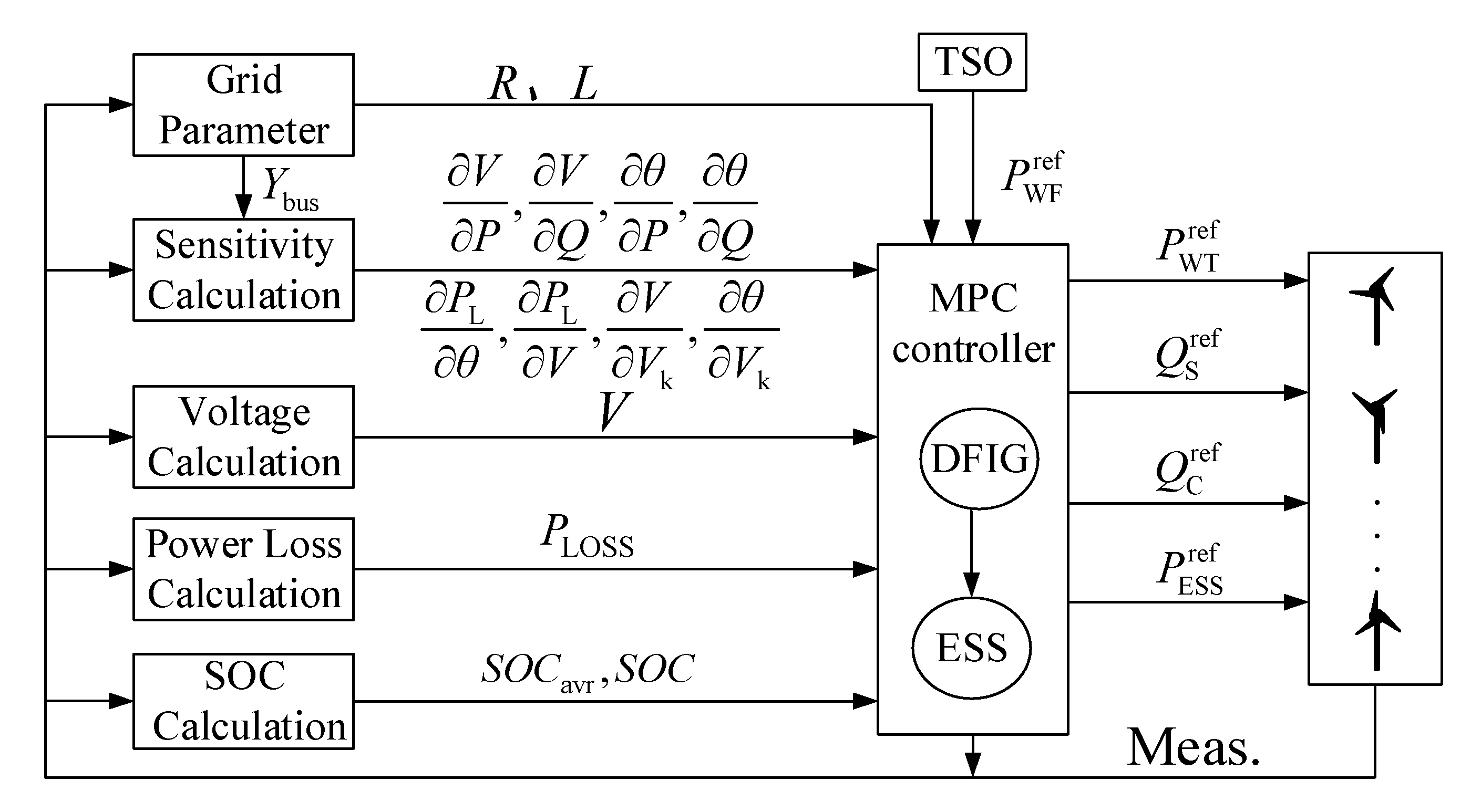
The structure of the presented active and reactive power coordinated control strategy is shown in Figure 2. The WF total active power reference is set by TSO and send to the WF controller. The MPC-based WF controller implements a two-stage optimization scheme.
The first stage controls all DFIGs inside the WF to follow the active power reference issued by TSO, and decreasing WTs fatigue loads, brought by the changes of WTs shaft torque and thrust force. And the total active power reference value of ESSs and the best active power reference of every DFIG WT are obtained by the controller.
In the second stage control, controller make the ESSs follow its power reference from the first stage control, while keep its SOCs to an average state. Meanwhile controller regulates the reactive power output of DFIG stator and GSC to minimize bus voltage deviation and decrease network power losses of WF, and consider the influence of active power outputs of WTs and ESSs.

3. WF Model

Figure 3 shows the structure of the DFIG WT equipped with an ESS. DFIG stator joins to the AC grid directly. DFIG rotor is linked to the AC network by a back-to-back PWM converter, including a rotor side converter (RSC), a GSC and an ESS.ESS contains an energy storage unit (ESU) and a DC/DC converter. The ESU is linked to a DC bus by a DC/DC converter to adjust charge/discharge power of ESU to track the active power reference from the WF controller.

3.1. RSC Model

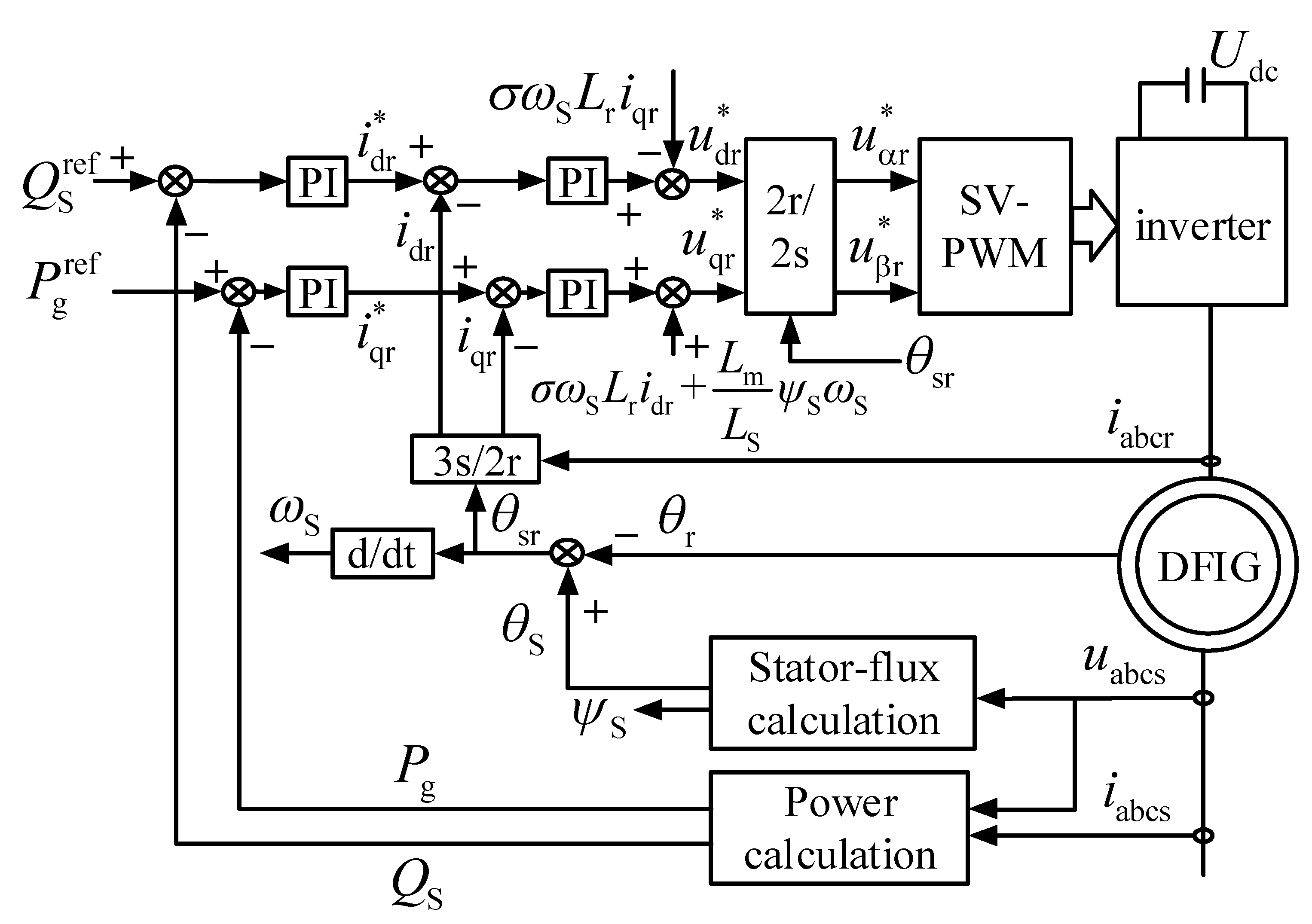
The RSC is mainly used to control active and reactive power output of DFIG. RSC could decouple active and reactive power by adjusting rotor current in a synchronously rotating reference frame oriented by the stator flux. Figure 4 shows the RSC control structure.
DFIG active power output is:
P g = L m ψ S ω S L S i qr + 3 2 U qr i qr
stator active power output is the first item in function (1), and GSC active power output is the second item.
DFIG reactive power is DFIG stator reactive power QS. QS is controlled through adjusting DFIG rotor d-axis current idr, its calculation formula can be derived and expressed as:
Q S = L m ψ S ω S L S i dr ψ S 2 ω S L S
where ψS is the stator flux, Lm is the mutual inductance, ωS is the supply angular speed, LS is DFIG stator inductance. Uqr is q-axis rotor voltage, iqr is rotor q-axis current.
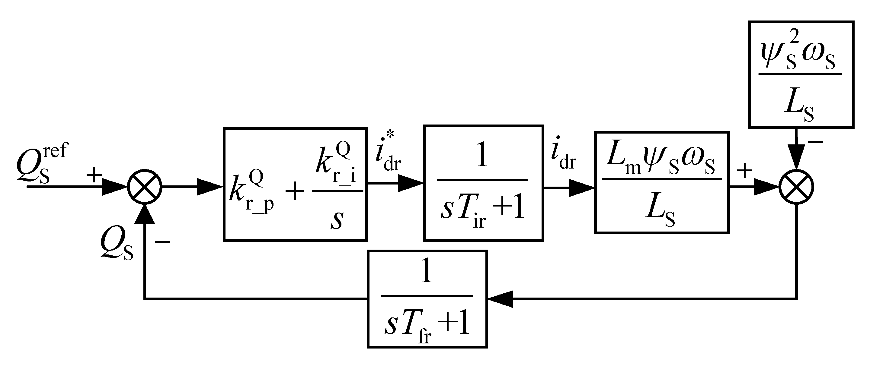
Normally, The time constant of power outer loop is much smaller than that of the current inner loop The first-order lag function could describe the dynamic behavior of the current loop. Hence, the model of RSC active power and reactive power could be simplified re which is shown in Figure 5 and Figure 6 spectively. Where k r _ P P , k r _ P Q , k r _ i P , and k r _ i Q are the proportional gain and integral gain of PI controllers, respectively. Tir is the time constant of current loop. Tfr denote filter time constant. Superscript ‘*’indicates reference value.
Define Δiqr, Δidr, ΔPg, ΔQS, Δ P g ref , ΔPint, Δ Q S r e f , and Δ Q i n t S are the incremental values between its current value and the initial value at operation point, respectively. Where Pint is the error integral of P g r e f and Pg, Q i n t S is the integral of error between Q S r e f and QS.
Then, RSC active power incremental state space model is as follows,
Δ i qr = 1 1 + s T ir ( k r _ P P + k r _ i P s ) ( Δ P g ref Δ P g )  
Δ P g = 1 1 + s T fr ( L m ψ S ω S L S + 3 2 U qr ) Δ i qr  
Δ P int = Δ P g ref Δ P g s  
The state space matrix form is,
Δ x ˙ P = A P Δ x P + B P Δ u P
where
Δ x P = [ Δ P g Δ P int Δ i qr ] T ,   Δ u P = Δ P g ref , A P = [ 1 T fr 0 L m ψ S ω S T fr L S + 3 U qr 2 T fr 1 0 0 k r _ P P T ir k r _ i P T ir 1 T ir ] ,   B P = [ 0 1 k r _ P P T ir ] T
The RSC reactive power incremental state space model is derived as follows,
Δ i dr = 1 1 + s T ir ( k r _ P Q + k r _ i Q s ) ( Δ Q S ref Δ Q S )
Δ Q S = 1 1 + s T fr L m ψ S ω S L S Δ i dr
Δ Q int S = Δ Q S ref Δ Q S s
The state space matrix form is,
Δ x ˙ Q S = A Q S Δ x Q S + B Q S Δ u Q S
where
Δ x Q S = [ Δ Q S Δ Q int S Δ i dr ] T ,   Δ u Q S = Δ Q S ref , A Q S = [ 1 T fr 0 L m ψ S ω S T fr L S 1 0 0 k r _ P Q T ir k r _ i Q T ir 1 T ir ] ,   B Q S = [ 0 1 k r _ P Q T ir ] T .

3.2. GSC Model

The DC bus voltage is adjusted by GSC, which offering reactive power support for WF AC grid at the same time. GSC can decouple DC voltage and reactive power control by adjusting current in a synchronously rotating reference frame oriented by the grid voltage [24]. Figure 7 shows the GSC control structure.
GSC reactive power in the grid-voltage-oriented synchronously rotating reference frame can be modeled as,
Q C = 3 2 U m i q
where Um is the grid phase voltage amplitude.
The same as the RSC, the GSC model is shown in Figure 8, k g _ P Q , k g _ i Q is the proportional gain and integral of PI controller, Tig denote current loop time constant, Tfg denote GSC filter time constant. Superscript ‘*’indicates reference value.
Define the Δiq, ΔQC, Δ Q C r e f , and Δ Q i n t C are the incremental values between its current value and the initial value at operation point, respectively, and Q i n t C is the integral of error between Q C r e f and QC. Superscript ‘*’indicates reference value. GSC incremental state space model is derived as follows,
Δ i q = 1 1 + s T ig ( k g _ P Q + k g _ i Q s ) ( Δ Q C ref Δ Q C )
Δ Q C = 1 1 + s T fg ( 3 2 U m ) Δ i q
Δ Q int C = Δ Q C ref Δ Q C s
The state space matrix form can be get,
Δ x ˙ Q C = A Q C Δ x Q C + B Q C Δ u Q C
where
Δ x Q C = [ Δ Q C Δ Q int C Δ i q ] T ,   Δ u Q C = Δ Q C ref , A Q C = [ 1 T fg 0 3 U m 2 T fg 1 0 0 k g _ P Q T ig k g _ i Q T ig 1 T ig ] ,   B Q C = [ 0 1 k g _ P Q T ig ] T .

3.3. ESS Model

The calculation formula of ESS stored energy CESS is,
C ESS = C ESS , 0 P ESS dt
where CESS,0 denotes the initial energy, and PESS denotes the charge/discharge power of ESS.
To enhance the DC side current response speed, a double closed loop control structure diagram of DC/DC converter, as shown in Figure 9. Figure 10 shows the ESS simplified block diagram. Where k d _ P P and k d _ i P denotes the proportional gain and integral of the PI controller. UESS denotes ESU voltage. Tid denotes the current loop time constant, Tfd denotes ESS filter time constant. Superscript ‘*’indicates reference value.
Define the ΔCESS, ΔiL, ΔPESS, Δ P E S S r e f and Δ P E S S i n t as the incremental value between its current value and the initial value at the operation point, respectively, and P E S S i n t is integral error of P E S S r e f and PESS. Therefore the ESS incremental state space model is derived as follows,
Δ C ˙ ESS = ( Δ P ESS + P ESS , 0 )
Δ i L = 1 1 + s T id ( k d _ P P + k d _ i P s ) ( Δ P ESS ref Δ P ESS )
Δ P ESS = 1 1 + s T fd U ESS Δ i L
Δ P ESS int = Δ P ESS ref Δ P ESS s
The state space expression of the ESS is,
Δ x ˙ E = A E Δ x E + B E Δ u E + E E
Δ y E = C E Δ x E
where
Δ x E = [ Δ C ESS Δ P ESS Δ P ESS int Δ i L ] T ,   Δ u E = Δ P ESS ref ,   Δ y E = Δ C ESS , A E = [ 0 1 0 0 0 1 T fd 0 U ESS T fd 0 1 0 0 0 k d _ P P T id k d _ i P T id 1 T id ] ,   B E = [ 0 0 1 k d _ P P T id ] T , E E = [ P ESS , 0 0 0 0 ] T , C E = [ 1 0 0 0 ] .

3.4. WT Model

The mechanical system model of the WT can be obtained according to the analysis in [25].
Let K RSC = L m ψ S ω S T fr L S + 3 U qr 2 T fr L S , and combine the RSC active power model and the WT model, the incremental state-space matrix of DFIG active power dynamic model is,
Δ x ˙ W = A W Δ x W + B W Δ u W + E W
Δ y W = C W Δ x W
where
Δ x W = [ Δ P g , Δ P int , Δ i qr , Δ β ref , Δ β , Δ ω g , Δ ω f ] T   , Δ u W = Δ P g ref ,   Δ y W = [ Δ T S Δ F t Δ P g ] T , A W = [ 1 T fr 0 K RSC 0 0 0 0 1 0 0 0 0 0 0 k r _ P P T ir k r _ i P T ir 1 T ir 0 0 0 0 0 0 0 0 0 K P T f K P T f + K i 0 0 0 K C , 0 T θ K C , 0 ref 1 T θ 0 0 η g 2 μ g J t ω f , 0 0 0 0 η g K β T J t η g K ω T J t η g 2 P g , 0 μ g J t ω f , 0 2 0 0 0 0 0 1 T f 1 T f ] , B W = [ 0 , 1 , k r _ P P T ir , 0 , 0 , 0 , 0 ] T , E W = [ 0 , 0 , 0 , K i ( ω f , 0 ω g rated ) , K C , 0 T θ ( θ 0 ref θ 0 ) , η g J t ( T a , 0 η g T g , 0 ) , 0 ] T , C W = [ η g J r μ g J t ω f , 0 0 0 0 η g 2 J g K β T J t η g 2 J g K ω T J t η g J r P g , 0 μ g J t ω f , 0 2 0 0 0 0 K β F K ω F 0 1 0 0 0 0 0 0 ] .
where θ denotes pitch angle, β = KCθ, KC = K0 + 2K1θ, where K0 and K1 are constants, Tθ denotes time constant of pitch servo function, Ta denotes aerodynamic torque, and Tg denotes generator torque, Kp and Ki denote the proportional gain and integral gain of pitch controller, ωf is filtered speed at which the generator speed ωg is filtered by the low-pass filter, Tf is filter time constant, ηg denotes gear box ratio, Jr denotes rotor mass, Jg denotes generator mass, Jt = Jr + η g 2 Jg is the equivalent mass, μg is the generator efficiency; TS denotes shaft torque, Ft denotes thrust force, KβT, KωT, KβF and KωF are the coefficients obtained the Taylor expansion of TS and Ft at the operating point, and subscript 0 is used to denote the initial value in control period.

3.5. Whole System Model

The continuous state-space matrix of a WF consist of NT WTs can be get as follows,
Δ x ˙ Wf = A Wf Δ x Wf + B Wf Δ u Wf + E Wf
Δ y Wf = C Wf Δ x Wf
where
Δ x Wf = [ Δ C ESS total , Δ P ESS total , Δ P ESS , int total , Δ i L total , Δ x W 1 , , Δ x W N T , Δ x Q S 1 , , Δ x Q S N T , Δ x Q C 1 , , Δ x Q C N T , Δ x E 1 , , Δ x E N T ] T , Δ u Wf = [ Δ P ESS , total ref , Δ P g , 1 ref , , Δ P g , N T ref , Δ Q S , 1 ref , , Δ Q S , N T ref , Δ Q C , 1 ref , , Δ Q C , N T ref ,   Δ P ESS , 1 ref , , Δ P ESS , N T ref ] T , A Wf = diag [ A E , A W , 1 , , A W , N T , A Q S , 1 , , A Q S , N T , A Q C , 1 , , A Q C , N T , A E , 1 , , A E , N T ] T , B Wf = diag [ B E , B W , 1 , , B W , N T , B Q S , 1 , , B Q S , N T , B Q C , 1 , , B Q C , N T , B E , 1 , , B E , N T ] T , E Wf = [ ( E E ) T , ( E W , 1 ) T , , ( E W , N T ) T , 0 1 × 3 N T , 0 1 × 3 N T , ( E E , 1 ) T , , ( E E , N T ) T ] T , C Wf = diag [ C E , C W , 1 , , C W , N T , I 3 N T , I 3 N T , C E , 1 , , C E , N T ] .
The discrete state space matrix is,
Δ x Wf ( k + 1 ) = A Wf , d Δ x Wf ( k ) + B Wf , d Δ u Wf ( k ) + E Wf , d  
y Wf ( k ) = C Wf , d Δ x Wf ( k )  

4. MPC Based Coordinated Active and Reactive Power Control for Wind Farm with ESSs

The DFIG-based WF requires the WF controller consider the coordinated control of the all the energy sources inside the WF. All WTs, RSCs, GSCs, and VSCs within the WF are optimally coordinated to reduce fatigue loads, keep the each bus voltage in a reasonable range and decrease network power losses. In order to decouple active and reactive power optimal control and keep fatigue loads at a minimum, the control strategy is divided into two steps. every DFIG active power reference and a total ESSs active power reference are produced by the controller in the first stage, which aims to follow the dispatch command and reduce the fatigue loads by minimizing variations in TS and Ft of WTs. The controller coordinates control the reactive power of DFIG stator and GSC inside this WF in the second stage, aims to keep the all buses voltage of WF in a feasible range, and reduces WF network power losses. Moreover, the WF controller regulates ESSs charge/discharge power to follow the ESSs active power reference obtained in the first step and keeps every ESS SOC value converging to average.

4.1. The First Stage Control

4.1.1. Objective Function

The WF controller reduces fatigue loads of WTs. In addition, in order to enable the ESS to operate stably for a long time, the CESS of ESS is controlled to keep at the intermediate level. Then the objective function can beget as follows,
min i = 1 N T k = 1 N P C ESS total ( k ) C ESS , mid total λ C 2 + Δ T S , i ( k ) λ T 2 + Δ F t , i ( k ) λ F 2
where NP denotes MPC predictive steps, and C E S S , m i d t o t a l denotes intermediate level of total ESS capacity. λC, λT, λF are the weighting coefficients for the total ESSs energy management, variations of TS and Ft, separately.

4.1.2. Constraints

The active power constraint of the WF is,
i = 1 N T P W , i ref + P ESS ref = P WF ref
The constraint of a WT is as follows,
0 P W , i ref P W , i avi ,   i N T
The constraint of total ESSs is as follows,
P ESS charge , total P ESS total P ESS discharge , total

4.2. The Second Stage Control

4.2.1. Objective Function

The first objective is voltage regulation, which aims to keep the each MV bus voltage and WT terminal bus voltage in a reasonable range [26]. Therefore, the objective function about voltage regulation is,
O b j V = k = 1 N P ( Δ V M V p r e ( k ) 2 + Δ V W p r e ( k ) 2 )
where Δ V MV pre = [ Δ V MV , 1 pre , Δ V MV , 2 pre , , Δ V MV , N MV pre ] T , NMV is the number of MV bus, Δ V W pre = [ Δ V W , 1 pre , Δ V W , 2 pre , , Δ V W , N T pre ] T , Δ V MV pre and Δ V W pre is the predictive incremental voltage of MV bus and WT terminal bus, separately, it can be get,
Δ V MV , i pre ( k ) = V MV , i ( t 0 ) + V MV , i P g Δ P g ( k ) + V MV , i P W Δ P ESS ( k ) + V MV , i Q S Δ Q S ( k ) + V MV , i Q C Δ Q C ( k ) V MV , i ref
Δ V W , i pre ( k ) = V W , i ( t 0 ) + V W , i P W Δ P W ( k ) + V W , i P W Δ P ESS ( k ) + V W , i Q S Δ Q S ( k ) + V W , i Q C Δ Q C ( k ) V W , i ref
Keep the total network power losses at a minimum is the second objective, which is,
O b j L = k = 1 N P ( P L O S S p r e ( k ) 2 )
where P L O S S p r e is the predictive value of network power losses,
P LOSS pre ( k ) = P LOSS pre ( t 0 ) + P LOSS P g Δ P g ( k ) + P LOSS P W Δ P W ( k ) + P LOSS Q S Δ Q S ( k ) + P LOSS Q C Δ Q C ( k )  
where sensitivity coefficients regarding power injections in (34), (35), In addition, (37) can be obtained by using the analytical method in [26].
The third objective is to ensure the SOC of each ESS converging to an average value, which is,
O b j S = i = 1 N T k = 1 N P S O C i ( k ) S O C a v r 2
According to (33), (36), (38), the objective function of the second step is,
min ( λ V O b j V + λ L O b j L + λ S O b j S )
where λV, λL, λS are the weighting coefficients for ObjV, ObjL, ObjS, respectively.

4.2.2. Constraints

For a distributed ESS, its active power reference constraint is as follow,
P E S S , i c h a r g e , a v i P E S S , i r e f P E S S , i d i s c h a r g e , a v i ,   i N T
where P ESS , i charge , avi and P ESS , i discharge , avi are the ESS available charging/discharging power. The reactive power of DFIG stator and GSC are constrained as follows,
Q S , i min Q S , i ref Q S , i max ,   i N T
Q C , i min Q C , i ref Q C , i max ,   i N T
where Q S , i m i n / Q C , i m i n and Q S , i m a x / Q C , i m a x are the minimum and maximum Var capacity of the DFIG stator and GSC, separately.
The entire charge/discharge active power output should be set equal to the total ESS active power reference obtained by the first stage as follow,
i = 1 N T P ESS , i ref = P ESS total

5. Case Study

5.1. Test System

A WF composed of 10 × 5 MW DFIG WTs with distributed ESSs is used to verify presented control strategy in the section. The WF modeling that considers the effects of turbulence and wakes is created by SimWindFarm, a toolbox for dynamic WF modeling, simulation and control. The control period TC, prediction horizon TP and the prediction sampling period ΔTP are set as 1 s, 5 s, and 0.1 s, separately. For the purpose of verify the effectiveness of the presented control scheme, the simulation results are contrast with the one without ESSs and reactive power control.

5.2. Control Performance

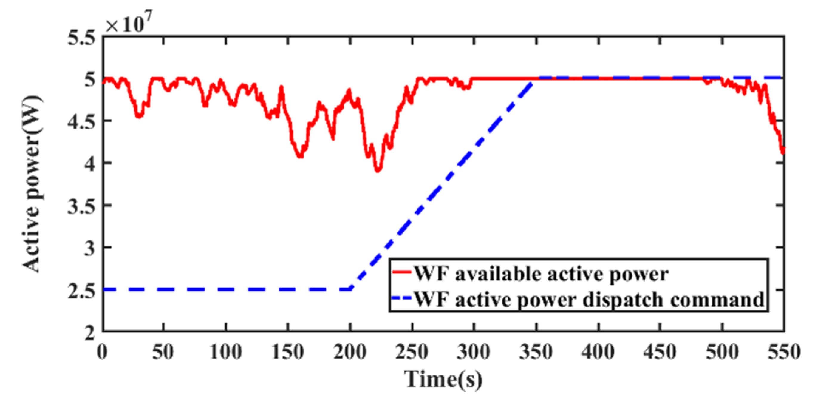
In the MATLAB/Simulink, the simulation time is set as 550 s. The total WF available active power and TSO dispatch demand are shown in Figure 11. During t = 0–280 s, the WF available power fluctuates between 38–50 MW. At t = 280 s, the total available active power begin increasing and reaches the maximum available power 50 MW at 300 s. The available active power gradually reduces after t = 480 s. For the WF dispatch demand, it is set as 25 MW during t = 0–200 s. During t = 200–340 s, increases from 25 MW to the rated value 50 MW. After t = 340 s, the active power reference is kept on 50 MW. Since the all WTs performances are similar, WT 4 was selected for illustration.

5.2.1. The First Stage Control Performance

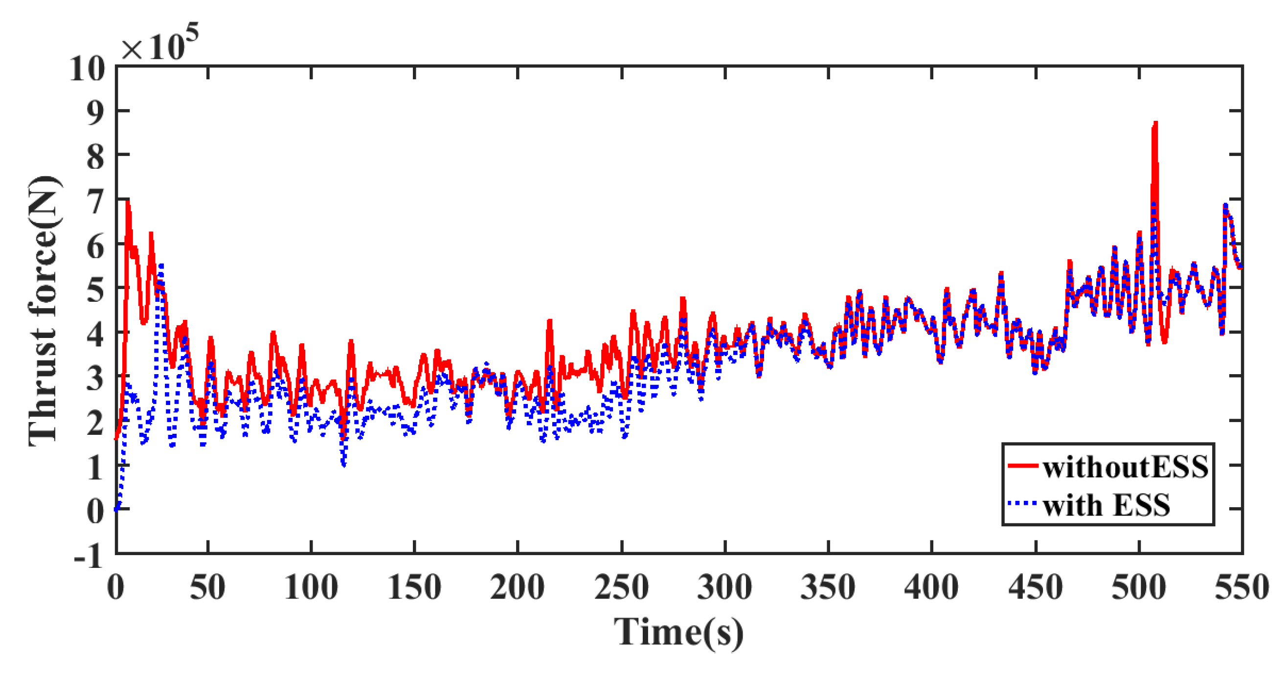
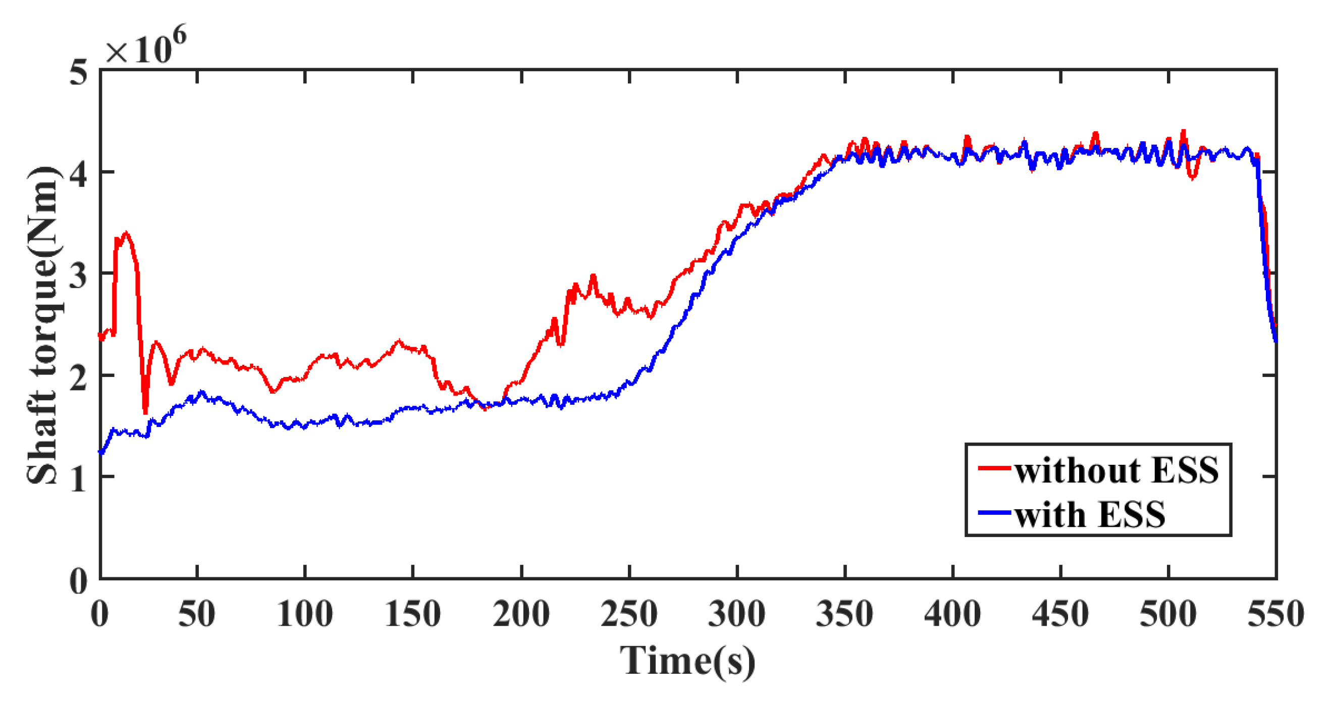
Figure 12 and Figure 13 show the thrust force and shaft torque changes of WT4. In Figure 12, thanks to the control effect of ESSs on WF active power adjustment, Ft variation with ESSs is smaller than that without ESSs. In Figure 13, during t = 0–340 s, the fluctuations of TS with ESSs is much less than that without ESSs. After t = 340 s, wind farm is operating in the maximum power point tracking (MPPT) mode, the changes in TS with ESSs is also less than that without ESSs. The fluctuations of thrust force are also less than that without ESSs. The control strategy proposed in this paper can effectively decrease the fatigue loads of DFIG WT by minimizing the changes of Ft and TS, then improve the security of the WF.

5.2.2. Simulation Analysis of the Second Stage

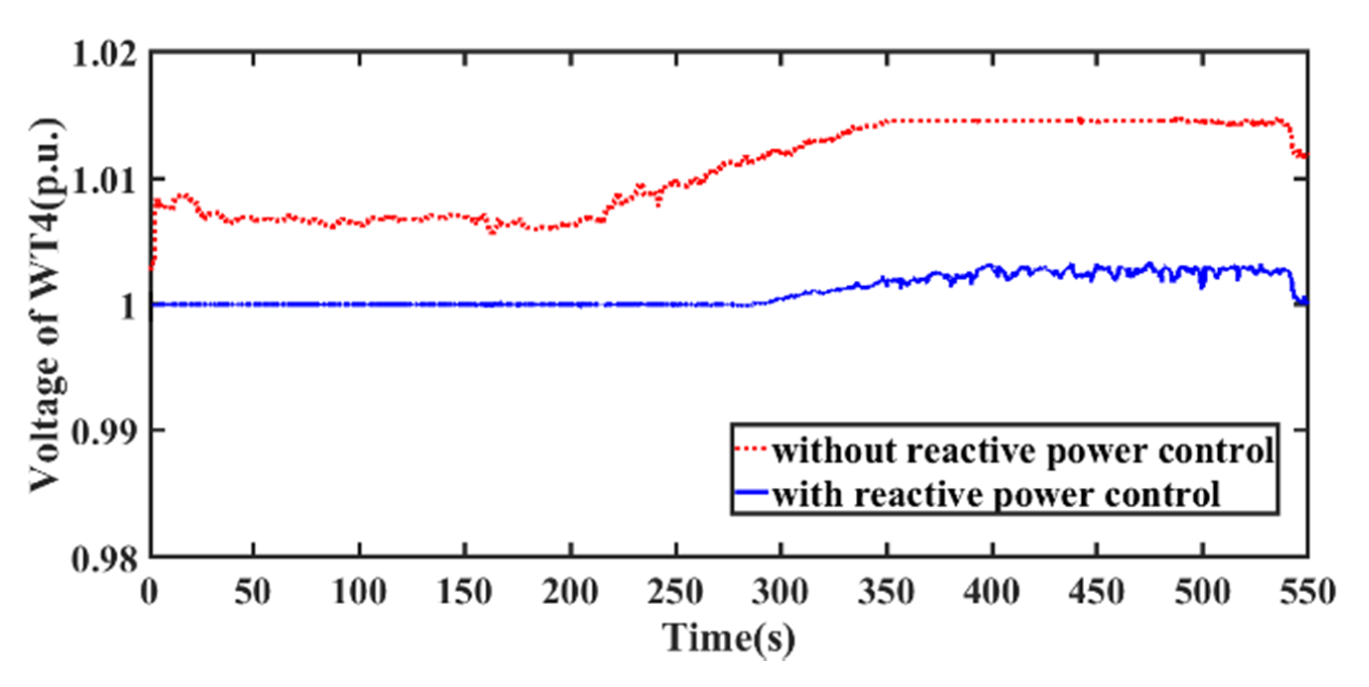
The WT 4 terminal voltage is shown in Figure 14. With the reactive power control, the voltage could be kept within the reasonable range effectively. The voltage deviation from nominal value with the reactive power control is significantly smaller than that without this control, which guarantee the WF secure operation.
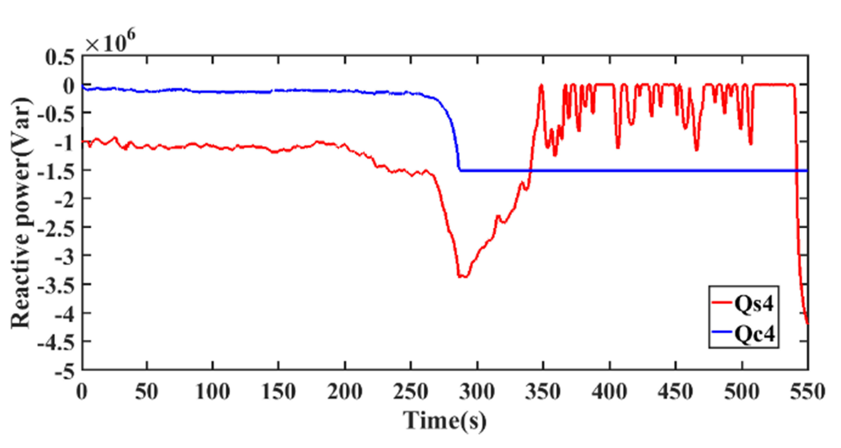
Figure 15 and Figure 16 show the active power and reactive power output of WT 4, respectively. During t = 0–300 s, the WT 4 stator and GSC absorb reactive power separately to regulate the WF voltages. After t = 300 s, due to the increasing active power output, the reactive power absorbed by stator is decreasing. At this time, the GSC supply reactive power. Due to GSC reactive power output limits, the WT 4 terminal voltage is increased, but it is still within the feasible operating range.
The WF total network power losses is shown in Figure 17. The network power losses with reactive power control is smaller than that without reactive power control.
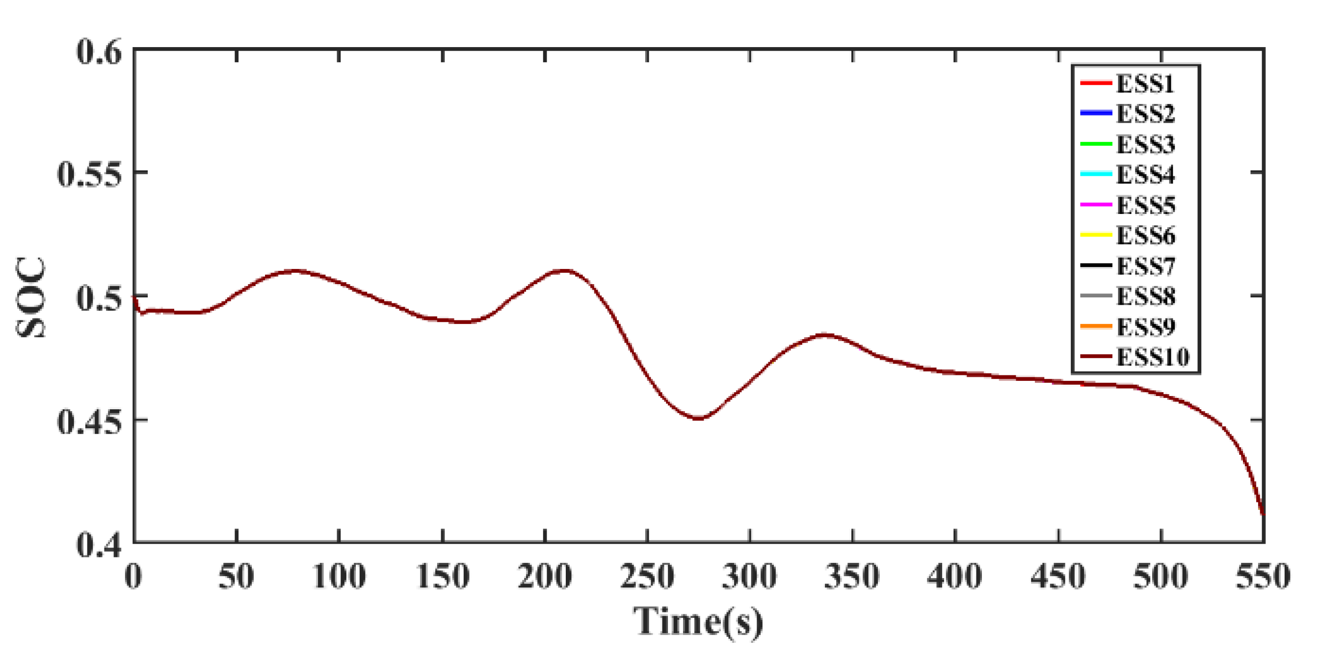
Figure 18 shows the SOC of each ESS. All the ESSs SOC are kept to the average value. From t = 0–350 s, the SOC fluctuates around 0.5, which means the proposed scheme manage the ESSs to keep the SOCs at the medium level. From t = 350–500 s, the WF output rated active power. The ESSs also needs output a spot of active power to decrease the WTs fatigue loads. The SOCs are decreased slightly, but they are kept closing to the medium level. After 500 s, the available power gradually decreases, and the dispatch command remain unchanged. The available power is less than the dispatch command. Therefore, all ESSs discharge power to track the dispatch command, causing SOCs decrease gradually.
Figure 19 shows the WF total active power output that equipped with distributed ESSs. With the ESSs, the WF total active power output could accurately follow the active power dispatch command from the TSO.

6. Conclusions

In this paper, an MPC based coordinated active and reactive power control strategy is proposed for DFIG wind farm with distributed ESSs, which coordinates the active and reactive power output among DFIG WTs, GSC and distributed ESSs inside wind farm to track the dispatch command the TSO set, reduce the fatigue loads of the WTs, and manage the distributed ESSs. Moreover, the control scheme can provide the best reactive power references for DFIG stator and GSC separately to regulate all the bus voltages and network power losses while track the dispatch command from TSO. Case studies show the control strategy could effectively decrease the fatigue loads, regulate the voltage in the feasible range, decrease the WF network power losses and ensure the SOC of each ESS converging to an average value. The presented coordinated active and reactive power control strategy is suitable for real-time control of large-scale wind farm.

Author Contributions

Conceptualization, H.C., X.L. (Xueping Li), G.W., Y.S., X.L. (Xiao Liu), D.L.; methodology, H.C.; software, H.C.; validation, H.C., X.L. (Xiao Liu) and G.W.; formal analysis, X.L. (Xiao Liu); investigation, G.W.; resources, Y.S.; data curation, X.L. (Xueping Li); writing—original draft preparation, H.C.; writing—review and editing, X.L. (Xueping Li); visualization, G.W.; supervision, X.L. (Xueping Li); project administration, D.L.; funding acquisition, D.L. All authors have read and agreed to the published version of the manuscript.

Funding

This research received no external funding.

Institutional Review Board Statement

Not applicable.

Informed Consent Statement

Not applicable.

Data Availability Statement

The study did not report any data.

Conflicts of Interest

The authors declare no conflict of interest.

Nomenclature

Abbreviations
DFIGDoubly fed induction generator
MPCModel predictive control
WTWind turbine
WFWind farm
ESSEnergy storage system
GSCGrid-side converter
TSOTransmission system operator
POCPoint of connection
RSCRotor-side converter
SOCState-of-charge
OLTCOn-load tap changer
ESUEnergy storage unit
Variables
P g DFIG active power output
QSDFIG stator reactive power
L m mutual inductance
ψ s stator flux
ωSsupply angular speed
LSDFIG stator inductance
Uqrq-axis rotor voltage
iqrrotor q-axis current
k r _ P P , k r _ P Q , k r _ i P , k r _ i Q proportional gain and integral gain of PI controllers
Tirtime constant of current loop
Tfrdenote filter time constant
Pinterror integral of P g r e f and Pg,
Q i n t S error between Q S r e f and QS.
QcGSC reactive power
Umgrid phase voltage amplitude
k g _ P Q , k g _ i Q proportional gain and integral of PI controller
Tigcurrent loop time constant
TfgGSC filter time constant.
Q i n t C error between Q C r e f and QC.
CESSESS stored energy
CESS,0initial energy
PESScharge/discharge power of ESS
k d _ P P , k d _ i P proportional gain and integral of the PI controller
UESSESU voltage
Tidcurrent loop time constant
TfdESS filter time constant
ΔCESS, ΔiL, ΔPESS, Δ P E S S r e f and Δ P E S S i n t as the incremental value between its current value and the initial value at the operation point
P E S S i n t error of P E S S r e f and PESS
θpitch angle
K0,K1constants
Tθtime constant of pitch servo function
Taaerodynamic torque
Tggenerator torque
Kp,Kiproportional gain and integral gain of pitch controller
ωfgenerator speed
ωglow-pass filter
Tffilter time constant
ηγgear box ratio
Jrrotor mass
Jggenerator mass
Jtequivalent mass
μggenerator efficiency
TSshaft torque
Ftthrust force
KβT, KωT, KβF and KωFare the coefficients obtained the Taylor expansion of TS and Ft at the operating point
NPMPC predictive steps,
C E S S , m i d t o t a l intermediate level of total ESS capacity
λC,λT,λFweighting coefficients for the total ESSs energy management variations of TS and Ft
NMVis the number of MV bus
Δ V W pre predictive incremental voltage of MV bus and WT terminal bus
P L O S S p r e predictive value of network power losses
λV, λL, λSweighting coefficients for ObjV, ObjL, ObjS,
P ESS , i charge , avi , P ESS , i discharge , avi ESS available charging/discharging power
Q S , i m i n / Q C , i m i n minimum Var capacity of the DFIG stator and GSC
Q S , i m a x / Q C , i m a x maximum Var capacity of the DFIG stator and GSC

References

  1. Zhang, D.; Zhang, X.; He, J.; Chai, Q. Offshore wind energy development in China: Current status and future perspective. Renew. Sustain. Energy Rev. 2011, 15, 4673–4684. [Google Scholar] [CrossRef]
  2. Menezes, D.; Mendes, M.; Almeida, J.A.; Farinha, T. Wind Farm and Resource Datasets: A Comprehensive Survey and Overview. Energies 2020, 13, 4702. [Google Scholar] [CrossRef]
  3. Hanifi, S.; Liu, X.; Lin, Z.; Lotfian, S. A Critical Review of Wind Power Forecasting Methods—Past, Present and Future. Energies 2020, 13, 5707. [Google Scholar] [CrossRef]
  4. Perveen, R.; Kishor, N.; Mohanty, S.R. Off-shore wind farm development: Present status and challenges. Renew. Sustain. Energy Rev. 2014, 29, 780–792. [Google Scholar] [CrossRef]
  5. Mohseni, M.; Islam, S.M. Review of international grid codes for wind power integration: Diversity, technology and a case for global standard. Renew. Sustain. Energy Rev. 2012, 16, 3876–3890. [Google Scholar] [CrossRef]
  6. Karthikeya, B.R.; Schütt, R.J. Overview of wind park control strategies. IEEE Trans. Sustain. Energy 2014, 5, 416–422. [Google Scholar] [CrossRef]
  7. Munteanu, I. Optimal Control of Wind Energy Systems: Towards a Global Approach; Springer: London, UK, 2008. [Google Scholar]
  8. Gasparis, G.; Lio, W.H.; Meng, F. Surrogate Models for Wind Turbine Electrical Power and Fatigue Loads in Wind Farm. Energies 2020, 13, 6360. [Google Scholar] [CrossRef]
  9. Zhao, H.; Wu, Q.; Guo, Q.; Sun, H.; Xue, Y. Optimal active power control of a wind farm equipped with energy storage system based on distributed model predictive control. IET Gener. Trans. Distri. 2016, 10, 669–677. [Google Scholar] [CrossRef] [Green Version]
  10. Kim, C.; Muljadi, E.; Chung, C.C. Coordinated Control of Wind Turbine and Energy Storage System for Reducing Wind Power Fluctuation. Energies 2018, 11, 52. [Google Scholar] [CrossRef] [Green Version]
  11. Yan, G.G.; Wang, Z.B.; Li, J.H.; Li, H.B.; Yang, Y.L. Optimization of Large Scale Energy Storage System for Relaxing Wind Power Centralized Transmission Bottlenecks. Adv. Mater. Res. 2014, 1070, 243–246. [Google Scholar] [CrossRef]
  12. Meghni, B.; Dib, D.; Azar, A.T. A second-order sliding mode and fuzzy logic control to optimal energy management in wind turbine with battery storage. Neural Comput. Appl. 2016, 28, 1417–1434. [Google Scholar] [CrossRef]
  13. Qu, L.; Qiao, W. Constant power control of DFIG wind turbines with supercapacitor energy storage. IEEE Trans. Ind. Appl. 2011, 47, 359–367. [Google Scholar] [CrossRef] [Green Version]
  14. Sarrias, R.; Fernández, L.M.; García, C.A. Coordinate operation of power sources in a doubly-fed induction generator wind turbine/battery hybrid power system. J. Power Source 2012, 205, 354–366. [Google Scholar] [CrossRef]
  15. Fortmann, J.; Wilch, M.; Koch, F.W.; Erlich, I. A novel centralised wind farm controller utilising voltage control capability of wind turbines. In Proceedings of the 16th PSCC, Glasgow, UK, 14–18 July 2008; pp. 914–919. [Google Scholar]
  16. Zhao, H.; Wu, Q.; Guo, Q.; Sun, H.; Huang, S.; Xue, Y. Coordinated voltage control of a wind farm based on model predictive control. IEEE Trans. Sustain. Energy 2016, 7, 1440–1451. [Google Scholar] [CrossRef] [Green Version]
  17. Schönleber, K.; Collados, C.; Pinto, R.T.; Ratés-Palau, S.; Gomis-Bellmunt, O. Optimization-based reactive power control in HVDC-connected wind power plants. Renew. Energy 2017, 109, 500–509. [Google Scholar] [CrossRef] [Green Version]
  18. Sakamuri, J.N.; Rather, Z.H.; Rimez, J.; Altin, M.; Göksu, Ö.; Cutululis, N.A. Coordinated voltage control in offshore HVDC connected cluster of wind power plants. IEEE Trans. Sustain. Energy 2016, 7, 1592–1601. [Google Scholar] [CrossRef]
  19. Zhang, B.; Hou, P.; Hu, W.; Soltani, M.; Chen, C.; Chen, Z. A Reactive Power Dispatch Strategy with Loss Minimization for a DFIG Based Wind Farm. IEEE Trans. Sustain. Energy 2017, 7, 914–923. [Google Scholar] [CrossRef]
  20. Guo, Q.; Sun, H.; Wang, B.; Zhang, B.; Wu, W.; Tang, L. Hierarchical automatic voltage control for integration of large-scale wind power: Design and implementation. Electr. Power Syst. Res. 2015, 120, 234–241. [Google Scholar] [CrossRef]
  21. Sguarezi Filho, A.J.; de Oliveira Filho, M.E.; Ruppert Filho, E. A predictive power control for wind energy. IEEE Trans. Sustain. Energy 2011, 2, 97–105. [Google Scholar]
  22. Liu, X.; Kong, X. Nonlinear model predictive control for DFIG based wind power generation. IEEE Trans. Automat. Sci. Eng. 2014, 11, 1046–1055. [Google Scholar] [CrossRef]
  23. Hu, J.; Zhu, J.; Dorrel, D. Predictive direct power control of doubly fed induction generators under unbalanced grid voltage conditions for power quality improvement. IEEE Trans. Sustain. Energy 2014, 6, 687–695. [Google Scholar] [CrossRef]
  24. Zhao, H.; Wu, Q.; Wang, J.; Liu, Z.; Shahidehpour, M.; Xue, Y. Combined active power and reactive power control of wind farms based on model predictive control. IEEE Trans. Energy Convers. 2017, 32, 1177–1187. [Google Scholar] [CrossRef] [Green Version]
  25. Huang, S.; Wu, Q.; Guo, Y.; Lin, Z. Bi-level decentralised active power control for large-scale wind farm cluster. IET Renew. Power Gener. 2018, 12, 1486–1492. [Google Scholar] [CrossRef]
  26. Guo, Y.; Gao, H.; Wu, Q.; Zhao, H.; Østergaard, J.; Shahidehpour, M. Enhanced Voltage Control of VSC-HVDC Connected Offshore Wind Farms Based on Model Predictive Control. IEEE Trans. Sustain. Energy 2017, 9, 474–487. [Google Scholar] [CrossRef] [Green Version]
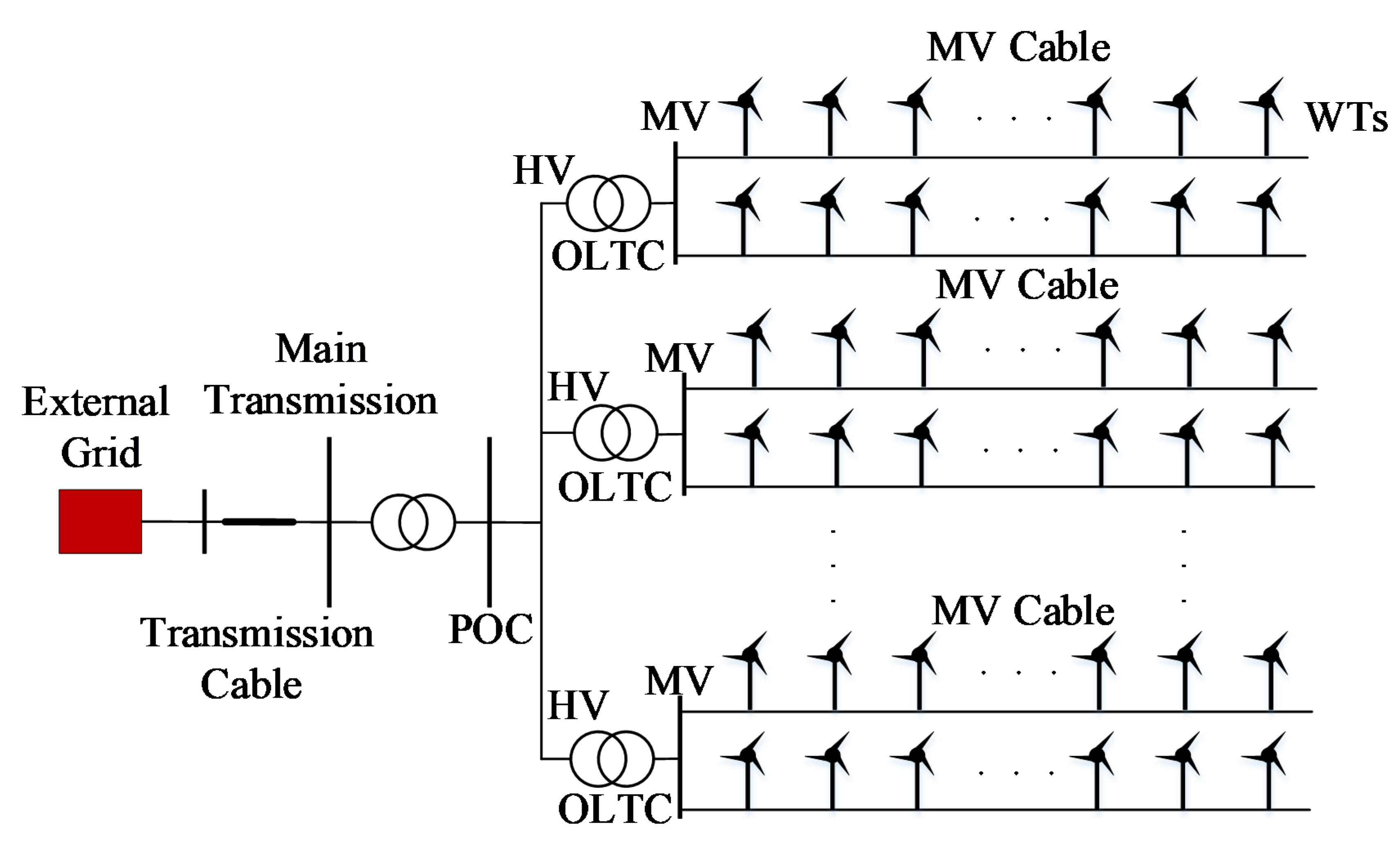
Figure 1. Configuration of a wind farm.
Energies 14 03906 g001
Figure 2. Structure of control scheme.
Energies 14 03906 g002
Figure 3. Structure of a DFIG WT equipped with an ESS.
Energies 14 03906 g003
Figure 4. The RSC control block diagram.
Energies 14 03906 g004
Figure 5. Active power control loop of the DFIG.
Energies 14 03906 g005
Figure 6. Reactive power control loop of the DFIG.
Energies 14 03906 g006
Figure 7. The GSC control block diagram.
Energies 14 03906 g007
Figure 8. The reactive power control loop of the GSC.
Energies 14 03906 g008
Figure 9. Control structure diagram of DC/DC converter.
Energies 14 03906 g009
Figure 10. The simplified block diagram of ESS.
Energies 14 03906 g010
Figure 11. WF total available and reference active power.
Energies 14 03906 g011
Figure 12. Thrust force of WT 4.
Energies 14 03906 g012
Figure 13. Shaft torque of WT 4.
Energies 14 03906 g013
Figure 14. Voltage of WT4.
Energies 14 03906 g014
Figure 15. Active power output of WT4.
Energies 14 03906 g015
Figure 16. Stator reactive power output and converter reactive power output of WT4.
Energies 14 03906 g016
Figure 17. Network power losses of wind farm.
Energies 14 03906 g017
Figure 18. SOC of ESSs.
Energies 14 03906 g018
Figure 19. Active power output of wind farm.
Energies 14 03906 g019
Publisher’s Note: MDPI stays neutral with regard to jurisdictional claims in published maps and institutional affiliations.