Article

Promoted Disappearance of CO2 Hydrate Self-Preservation Effect by Surfactant SDS

1
State Key Laboratory of Frozen Soil Engineering, Northwest Institute of Eco-Environment and Resources, Chinese Academy of Sciences, Lanzhou 730000, China
2
University of Chinese Academy of Sciences, Beijing 100049, China
3
Western China Energy & Environment Research Center, Lanzhou University of Technology, Lanzhou 730050, China
*
Authors to whom correspondence should be addressed.
Energies 2021, 14(13), 3909; https://doi.org/10.3390/en14133909
Submission received: 13 May 2021 / Revised: 17 June 2021 / Accepted: 23 June 2021 / Published: 29 June 2021
(This article belongs to the Special Issue Advances in Gas Hydrate Technology)

Abstract

:
The capture, storage and utilization of CO2 through hydrate-related technology is a promising approach to addressing the global warming issue. Dissociation is required after the transportation of CO2 gas in the form of a self-preserving hydrate. In order to investigate the dissociation behaviors as the self-preservation effect is removed, CO2 hydrates were frozen, and then the self-preservation effect was removed through uniform heating. An evident dependence of hydrate dissociation duration on the initial dissociation rates after losing the preservation effect was observed. The results in the silica gel powder and sodium dodecyl sulphate solution showed significant reductions in the initial dissociation temperatures and a slight decrease in the initial dissociation rates when compared with those of pure water. The reductions in the former were 2.88, 2.89, and 5.73 °C in silica gel, sodium dodecyl sulphate, and a combination of the two, respectively, while the reductions in the latter were 0.12, 0.12, and 0.16 mmol/min, respectively. As the results are inconsistent with the conventional mechanism elucidating a self-preservation effect, the ice shell theory was hence further supplemented by introducing innovative contribution factors—nonenclathrated liquid water and gas molecules dissolved inside. These findings are expected to provide references for CO2 gas transportation and usage of the self-preservation effect.

1. Introduction

Gas hydrates are crystalline compounds composed of water and gas. The gas molecules (guests) are trapped in water cavities (host) composed of hydrogen-bonded water molecules [1]. Various types of gas hydrates [2] presenting different applicable contributions [3,4,5,6] have been found both in nature and in the laboratory setting. The favorable conditions for CO2 hydrate formation offer potential ways of mitigating climate warming through CO2 seabed storage technology [7,8] and CO2 replacement for CH4 in methane hydrate [9,10,11]. Other applications (such as seawater desalination [12,13], gas purification [14,15,16], cool storage [17,18], and biogas upgrading [19,20]) have also ignited widespread concern in recent years. Before these applications, CO2 hydrate storage and its safe and efficient transportation are crucial steps. In order to solve this problem, plant-scale demonstration studies on hydrates are underway [21] and innovative technology (that is, the application of the self-preservation effect of hydrates) has been proposed. The so-called hydrate self-preservation effect is a phenomenon in which gas hydrates can maintain stability even at atmospheric pressure in some non-equilibrium temperature regions below the freezing point [22,23,24]. Due to the extremely slow dissociation rate under this state, gas hydrates could be efficiently and successfully transported at atmospheric pressure, and the utilization of the self-preservation effect is therefore undoubtedly a promising approach.
In order to better use this technology, it is necessary to understand its origins and characteristics. The dissociation rates of “self-preserving” methane hydrate were measured by Takeya et al. [25,26], at various temperature ranges, and the authors suggested that at the initial dissociation stage, a layer of ice forms on the hydrate surface and then prevents further dissociation. The influence of hydrate particle size and ice structure on the self-preservation effect was subsequently investigated, further showing that the generation of the effect depends on the action of the ice shell and the interaction between host and guest molecules [27,28,29]. The dissociation processes of structure type I (SI) and II (SII) hydrates at 193–290 K [30] and 190–273 K [31] were also studied by Stern et al., using successive temperature delaying and the rapid decompression method. According to the dissociation rates of methane hydrate measured between −7.5 and 0 °C at normal pressure, Shirota et al. [32] noted that the dissociation rate at −5 °C was the lowest. In addition, the influences of the hydrate surface structure, ice “defects” [33], ice particle size [34,35] and thermodynamic conditions, as well as the influences of phase composition [36] and supercooled water [37] on the self-preservation effect, have been considered by researchers.
As mentioned above, many research conclusions on the formation mechanism of the effect and dissociation rules of “self-preserving” hydrates have been provided. However, the disappearance patterns of this effect and the control mechanisms behind them (which are significant for further utilization of hydrates after being transported to their intended destinations) have rarely been reported in the literature. Additionally, few studies have examined the influence of additives [38,39] on the self-preserving CO2 hydrate. Therefore, the main purpose of this study is to further understand the dissociation characteristics of the CO2 hydrate after the self-preservation effect is removed and the role of SDS in the dissociation process. Using a uniformly increasing temperature method, the self-preservation effects of CO2 hydrates formed within various reaction systems (including pure water, silica gel (SG) powder, and sodium dodecyl sulphate (SDS) solution) were removed slowly, and the disappearance patterns of the effect were investigated in detail.
On the base of a novel perspective, i.e., the relationship between gas content and the initial decomposition temperature (IDT) or initial decomposition rate (IDR), analysis of the influence of ice on the hydrate self-preservation effect is executed in terms of the ice shell theory in this study. The role of SDS in the dissociation process of the self-preserving hydrate was also clarified. Finally, some novel factors controlling the self-preservation effects were proposed, supplementing the currently existing theories and thus providing references for the efficient transportation of CO2 gas through the hydrate self-preservation effect. The main conclusions of this study can be summarized as follows:
(1) Both SDS and silica gel can reduce the IDT and IDR of the self-preserving hydrate, and there is synergy when they exist together. (2) The dissociation time and ice content are directly and inversely proportional to the IDR of self-preserving hydrates, respectively. (3) The self-preservation effect is a complicated process that is not entirely caused by ice shells.

2. Materials and Methods

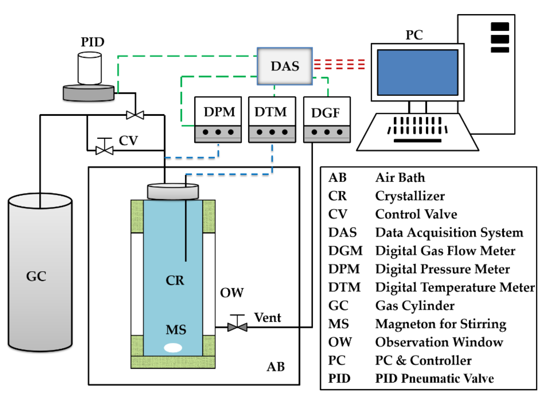
2.1. Experimental Apparatus and Materials

As shown in Figure 1, the core of the experimental system is a crystallizer, made of 316 stainless steel cylinders, with a magnetic stirrer inside and observation windows on both sides, of which the diameter and height are 45 and 130 mm, respectively. The crystallizer is wrapped in a water vest connected to a low-temperature circulating cooling bath. Temperature can be controlled accurately, in the range of −50~150 °C ± 0.1 °C. The pressure and temperature inside the crystallizer are measured using a digital pressure meter (DPM) and temperature meter (DTM), respectively. The CO2 gas with high pressure is stored in a gas cylinder also made of 316 stainless steel cylinders. There is a proportional-integral-derivative (PID) pneumatic valve located between the crystallizer and the cylinder, allowing the crystallizer to be pressurized through this PID valve. There is a vent at the bottom of the crystallizer, which is connected to a digital gas flow meter (DGM). The measurement range of the DGM is 0~5 L/min, the resolution is 0.001 L/min, and the precision is ±0.12%. The DGM, DPM, and DTM are controlled through a data acquisition system (DAS). During the experiments, all of the measured parameters were recorded and saved by the DAS at an interval of 5 s.
CO2 gas with a purity of 99.99% was chosen to form the hydrate. During the formation experiments of CO2 hydrates, sodium dodecyl sulphate (SDS) was widely applied as a promoter [40,41,42]. Therefore, besides being formed in pure water, CO2 hydrates were also formed in SDS solution. The transfer rate of gas to the aqueous phase can be significantly enhanced by SDS [43], and a 1 wt% is an effective concentration for enhancing the hydrate formation rate [42]. An SDS solution with 1 wt% concentration was therefore prepared using analytical grade SDS and deionized water with resistivity higher than 18.00 MΩ·cm, which was self-made in the lab. In order to ensure the comprehensiveness of the research results, silica gel powder, produced by Yucheng Chemical (Shanghai, China) Co., Ltd. (Figure S1, see Supplementary Materials), was also chosen as a porous medium in which CO2 hydrates were formed. The medium density is 0.35 g/cm3, the porosity is 77.44%, and the average particle size is between 25 and 58 μm. At the saturated state, the water content of the medium is Wwater/Wmedia = 2.2:1. During all formations, the utilized experimental media are all non-saturated, possessing a fixed water content of Wwater/Wmedia = 1.5:1. This water content results in a large gas–water contact area and enormous interconnected pore spaces, facilitating the formation of the hydrate [44]. As a result, high water conversion ratios of hydrate formation can be achieved through this water content [45,46].

2.2. Experimental Procedure

CO2 hydrates were formed in two liquid phases (i.e., pure water and SDS solution (abbreviated as PW and SS)) and one porous medium containing two different liquids (i.e., silica gel powder mixed with pure water and SDS solution (abbreviated as SG/PW and SG/SS)). Four temperatures (8.5, 6.5, 3.5, and 0.5 °C) were designed for the formation experiments, as shown as Table S1 (See the Supplementary Materials). The corresponding pressure values of the phase equilibrium of the CO2 hydrate were calculated as 3.67, 2.77, 1.68, and 1.32 MPa (Table S1), with CSMGem software (Natural Gas Hydrate Center, Colorado School of Mines).
Before each formation experiment in liquid phases, 104 mL of PW or SS was injected into the crystallizer. For those in porous media, a certain quality of silica gel powder also containing 104 mL PW or SS was charged. The initial temperature of the crystallizer was set higher than the pre-designed temperature by 2.5 °C. The crystallizer was then pressurized to the corresponding phase equilibrium value through the PID valve and remained constant. As stirring was required, the magnetic stirrer was opened, and the stirring speed was fixed at 200 r/min. The whole system was left undisturbed for over 12 h under the constant conditions to allow the CO2 to sufficiently dissolve in water. The temperature was subsequently uniformly reduced by 4 °C in 80 min and then remained constant under the constant pressure condition. Finally, a 1.5 °C subcooling driving force was provided for each formation experiment of the CO2 hydrate.
After the hydrate was sufficiently formed, the PID valve was turned off. The temperature was lowered below 0 °C rapidly to freeze the as-formed hydrate for over 10 h. Free gas in the crystallizer was then released slowly through the vent (Figure 1). Even under atmospheric pressure, frozen hydrates dissociate very slowly and enter into the self-preserving state. As reported, the optimum temperature condition of the self-preservation effect of the methane hydrate is about −5 ± 1 °C [30,31], and the temperature utilized to freeze the as-formed hydrates in the liquids was −6 °C. Considering the fact that there are a large number of capillaries within silica gel powder, another two low temperatures (−8 °C and −10 °C) were also used to freeze the as-formed hydrates in the porous medium.
After the self-preserving state of hydrate was maintained over 8 h, the temperature in the crystallizer was uniformly raised to the initial set value at a rate of 3 °C/h. In addition to the rise in temperature, the self-preservation effect gradually disappeared, and the hydrate began to dissociate. The DGM recorded the entire change process of the flow rate of released gas from the dissociating hydrate.

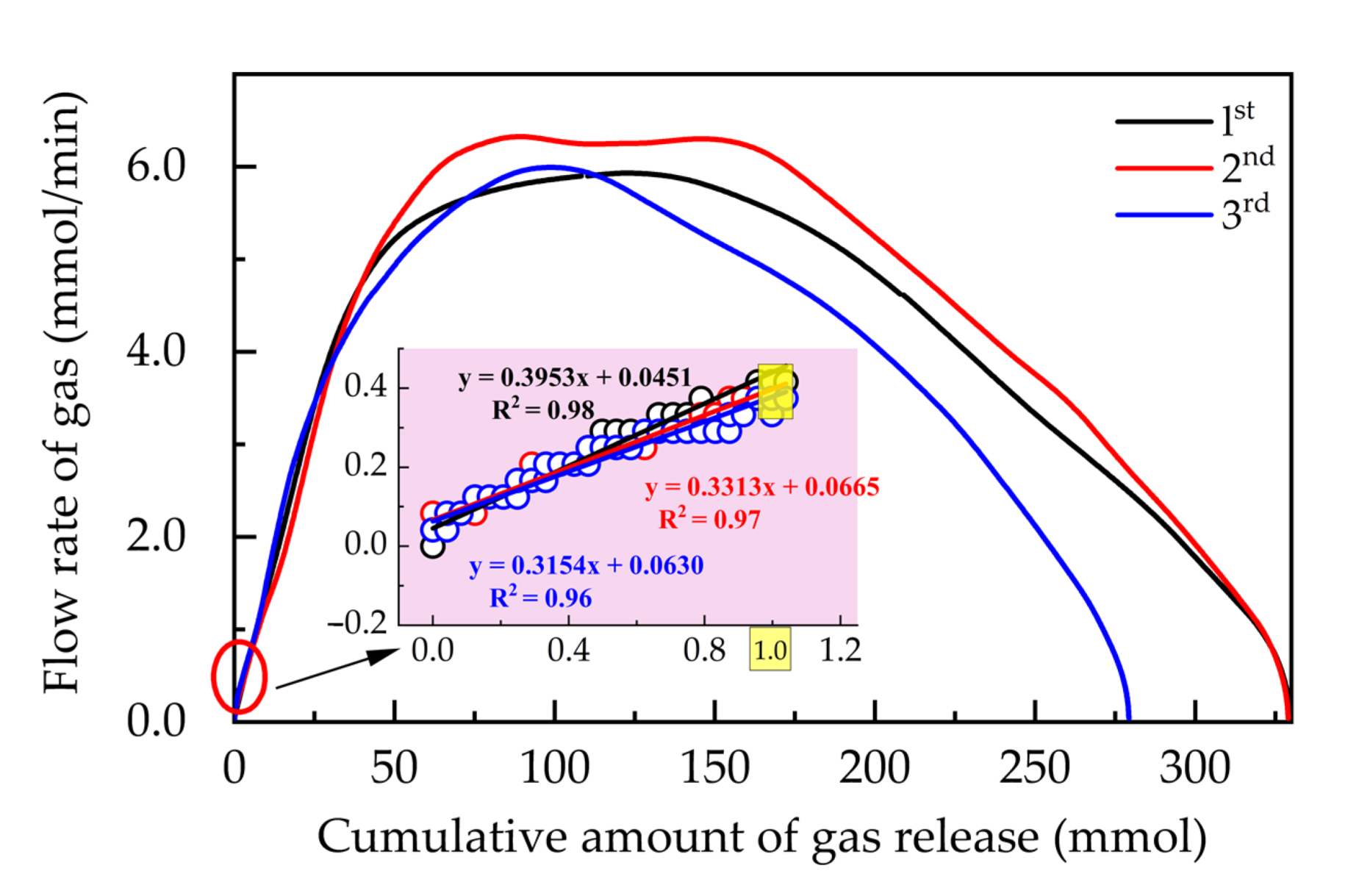
2.3. Calculation Method

As shown in Figure 2, due to the instantaneous opening/closing performance of the PID valve to retain constant pressure, the profile of the CO2 uptake against time during the entire hydrate formation process consists of many separated segments and presents a sawtooth wave shape. Over each separated segment (in Figure 2A,B), the amounts of gas uptake were calculated, and the total amount was obtained by summing up the separated ones with the following formulas:
n = n i
n i = P s t a × V Z s t a × R × T P f i n × V Z f i n × R × T
where n is the total amount of gas (with a unit mmol), ni is the calculated amount of gas uptake during each separated segment (mmol), P is the measured pressure in the crystallizer (MPa), V is the volume of the headspace or residual pores of the porous medium in the crystallizer (mL), T is the temperature (K), and R = 8.314 J/(mol·K). The subscripts “sta” and “fin” represent the starting and ending points of each separated segment, respectively. Z is the gas compressibility factor under a specific temperature and pressure conditions, calculated by the Benedict–Webb–Rubin–Starling equation of state [47].
During the dissociation process of the hydrate under atmosphere pressure and room temperature, the flow rates of the released gas were measured by the DGM with the unit L/min. Using the gas state equation, this unit was finally converted into mmol/min.

3. Results

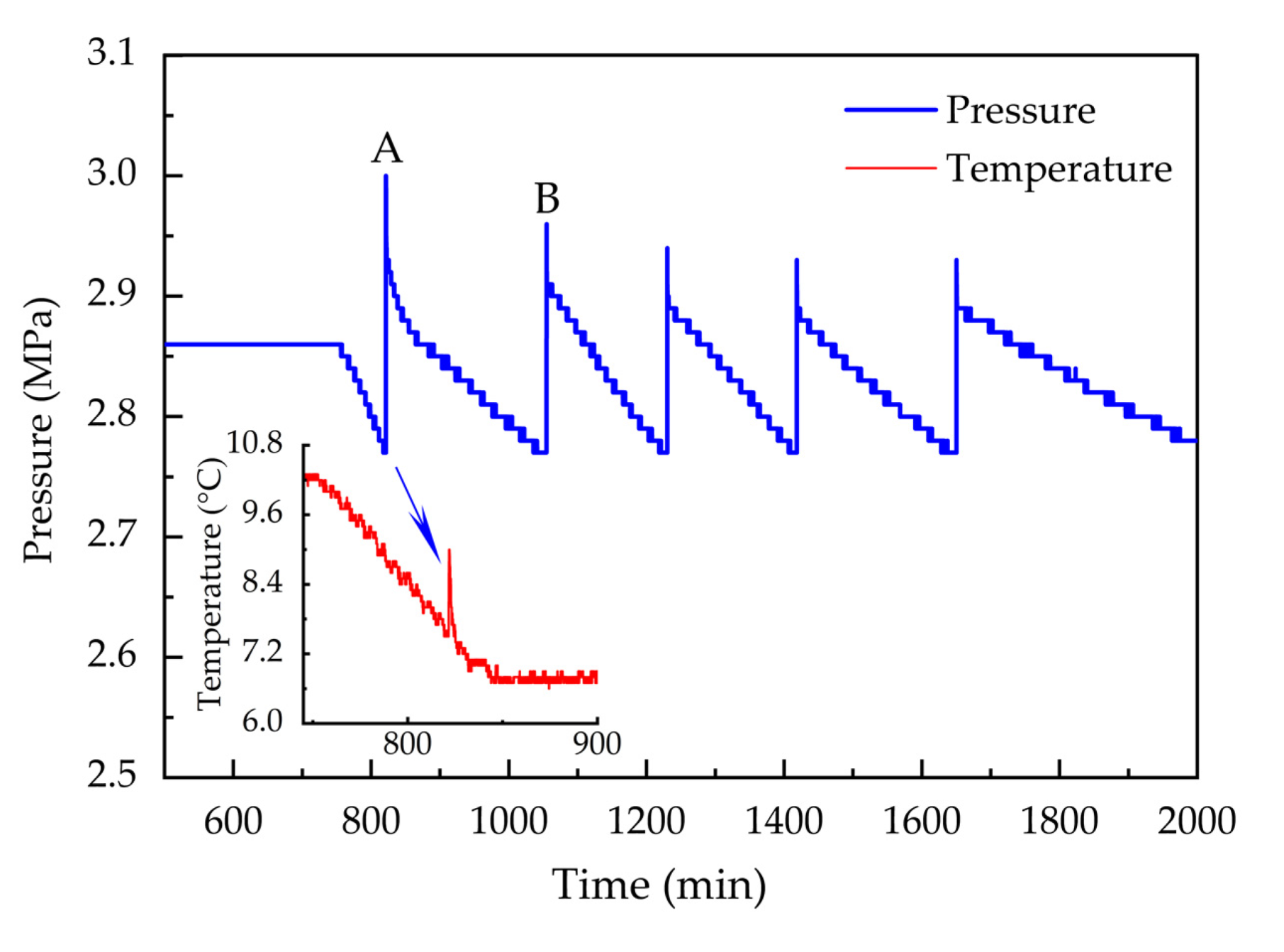
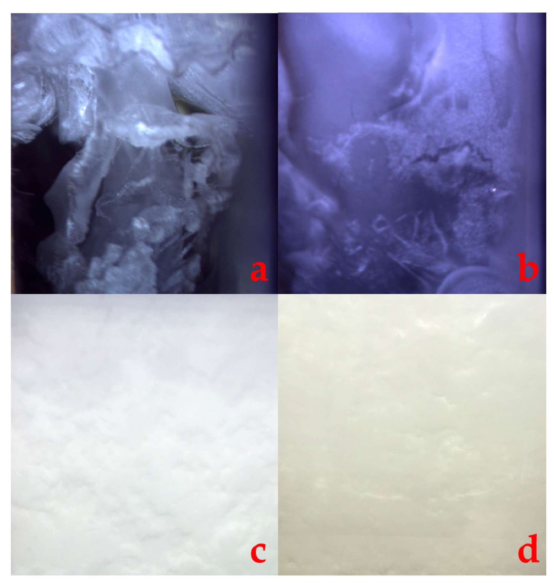
3.1. CO2 Hydrate Formation and Disappearance of Its Self-Preservation Effect

Figure 2 shows the changes in temperature and pressure during the entire CO2 hydrate formation process. In addition to the reduction in temperature, the hydrate began nucleating in PW and acutely released heat. Hydrate crystals began growing and continuously consumed gas. Figure 3 shows images of CO2 hydrate formation in four reaction systems. CO2 gas was hence repeatedly replenished into the crystallizer through the PID pneumatic valve, which presented as several sawtooth wave shapes on the pressure curve (e.g., in Figure 2A,B). After being frozen thoroughly, the as-formed hydrate can be dissociated through a method of continuously raising the temperature. Figure 4 shows one complete dissociation process consisting of three successive stages. During stage I, in addition to the release of free gas, the measured gas flow rate abruptly rose, and the temperature dramatically decreased. After that, the flow rate returned to the original 0 mmol/min and the temperature returned to the pre-set value −6 °C at stage II, at which point the hydrate was in a self-preserving state under normal pressure. During stage III, while being heated continuously, the frozen hydrate gradually lost its self-preservation effect and began dissociating. Because hydrate dissociation is an endothermic process, the change curves for temperature deviate from the original trends. These obvious deviating positions were defined as the initial dissociation points of temperature (IDTs), as shown in Figure 4, and those points in fact characterize specific temperature conditions at which the self-preservation effect is removed and the frozen hydrate begins dissociating. Because hydrates were formed under various experimental conditions, the specific locations of the IDT and change curves for the gas flow rate present obvious difference. As shown in Figure 4, the initial dissociation rates of hydrates are all 0 mmol/min. The flow rates were then plotted against the cumulative amounts of the released gas. As shown in Figure 5, while the cumulative amounts are less than 40 mmol, the relations between the flow rate and cumulative amount all exhibit superior linearity. Hence, the initial dissociation rate (IDR) of the hydrate was defined as the measured instantaneous flow rate when the cumulative amount of gas reached 1 mmol in this study. The specific values of the IDP and IDR were then counted and analyzed to investigate the disappearance patterns of the self-preservation effect of hydrate and the control mechanism behind them.

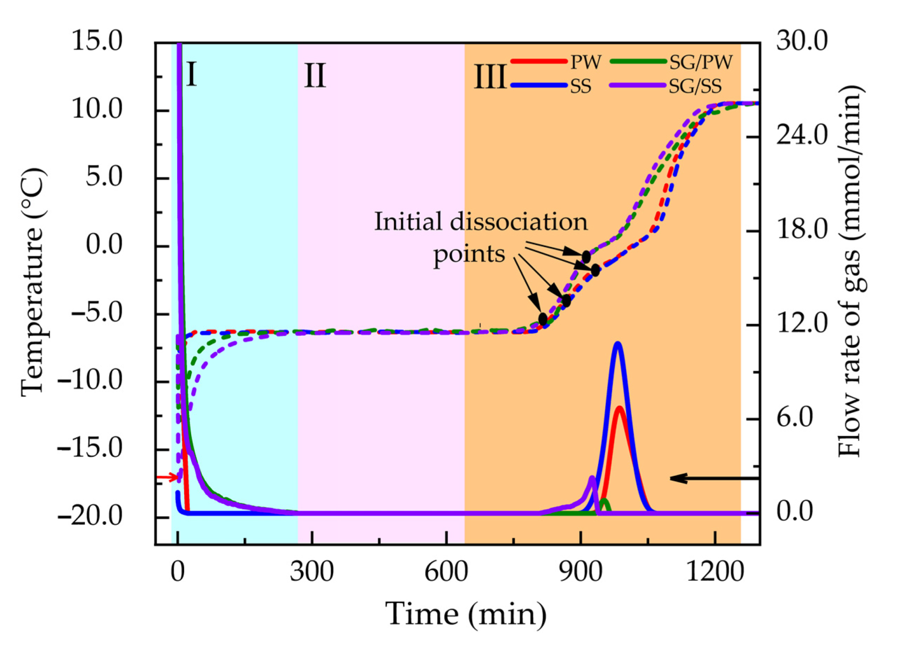
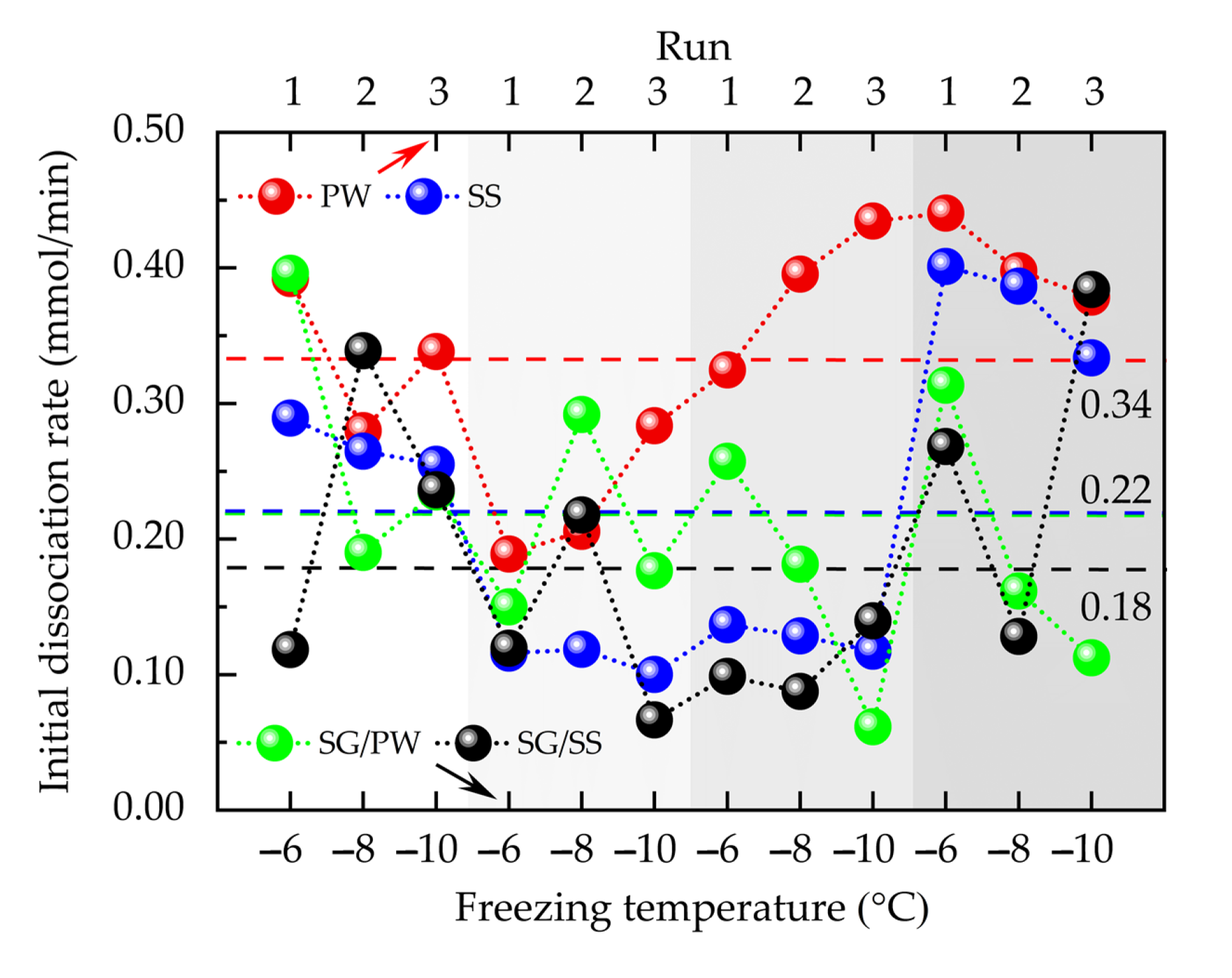
3.2. Influence of Medium and Experimental Conditions on IDT and IDR

Figure 6 shows that the IDTs of the self-preserving hydrates were significantly influenced by the experimental medium on which the hydrate was formed. The IDTs in PW are the highest, with an average value of −0.43 °C, followed by those in SG/PW and SS, with average values of −3.31 and −3.32 °C, respectively. The IDTs in SG/SS are the lowest and have an average value of −6.16 °C. In addition to the increase in chosen temperature, the IDTs tended to slightly increase. Although the IDTs in SS and SG/PW had almost the same average values (i.e., −3.31 and −3.32 °C, respectively), the specific values of SG/PW at different frozen temperatures presented obvious differences (i.e., −1.57 °C at the freezing temperature of −6 °C, −2.60 °C at −8 °C, and −5.93 °C at −10 °C). Similarly, there was an obvious difference in values of SG/SS (i.e., −4.38 °C, −6.95 °C, and −7.15 °C). As shown in Figure 6, in addition to the decrease in frozen temperatures, the IDTs in the silica gel powder tended to decline. A comparison Figure 6 and Figure 7 shows that the change rules of the IDR are similar to those of the IDT. The values of the IDRs in PW are the highest, with an average of 0.34 mmol/min, followed by those in SS and SG/PW with the same average of 0.22 mmol/min, while SG/SS has the lowest average value at 0.18 mmol/min. The IDRs followed different change rules in different reaction systems; values in SG/PW tended to decline with the decrease in frozen temperature, with an average value 0.28 mmol/min at −6 °C, 0.21 mmol/min at −8 °C, and 0.15 mmol/min at −10 °C. On the contrary, the values in SG/SS tended to increase, with 0.15 mmol/min, 0.19 mmol/min, and 0.21 mmol/min.

3.3. Relations between IDR and Ratio of Total Dissociation Time to Ice Content
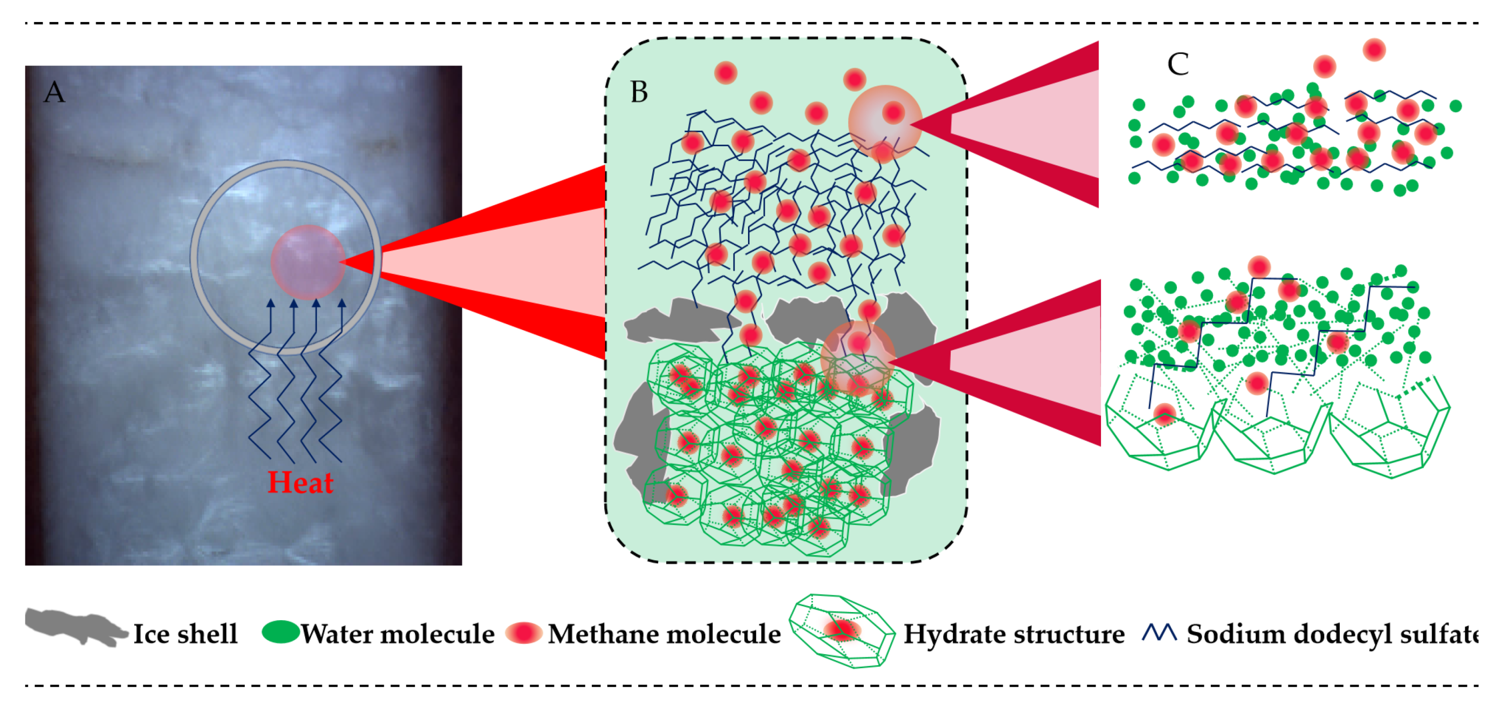
When the self-preservation effect disappeared, the hydrate began to slowly dissociate and finally release all of the gas contained inside after a certain period of time, implying the end of entire experiment. Besides the initial dissociation properties, the total durations of the dissociation processes were therefore also measured. As shown in Figure 8, the dissociation durations were prolonged by the SDS solution. The averages of durations in PW and SG/PW are almost the same (i.e., 101.66 and 107.68 min, respectively). With the SDS solution, these values improved by about 50% (i.e., 157.30 min in SS and 159.84 min in SG/SS), meaning that the gas-releasing efficiency of the hydrate under the self-preserving state can be significantly lowered by the surfactant SDS. Figure 9 shows the relation between the dissociation time (Figure 8) and IDR (Figure 7); that is, the dissociation time significantly depends on the IDR. This superior inverse proportional correlation, R2 = 0.70, means that along with disappearance of the self-preservation effect, the higher the initial dissociation rate (IDR), the shorter the dissociation duration.
In order to investigate the key influencing factor of the IDR, the final conversion rates of liquid water during formations of the hydrate were calculated. Considering the fact that the formed hydrates were all thoroughly frozen at negative temperatures, the calculation results were then subtracted from 100% to characterize the ice content contained in the frozen hydrates. Figure 10 shows the relation between the calculated ice content and IDR; that is, the IDR presents an obvious dependence on the ice content in the frozen hydrate, with an R2 = 0.67 of the fitted linear equation. This positive proportional correlation means the higher the ice content in the frozen hydrate, the greater the IDR.

4. Discussion

Through an X-ray diffraction experiment and an analysis carried by Yakushev et al. [24,25], the formation of the self-preservation effect was explained to be due to an as-formed ice shell outside the hydrate crystals (i.e., the ice shell theory). According to this theory, the IDR, when the effect begins disappearing, should present a reverse proportional correlation with the ice content contained in frozen hydrates, but our research shows exactly the opposite pattern (Figure 10). In our research, compared with the IDT in PW, that in the other three media was significantly reduced (Figure 6), which indicates that hydrate dissociation can be efficiently achieved via SDS effectively. In fact, as is known, the surfactant SDS utilized in this study is only one kind of dynamic additive for the hydrate formation, which does not transform the thermodynamic equilibrium conditions of hydrates [48,49,50]. This promotion action is carried out by improving water molecule activities and then by gas dissolution capabilities [51]. Hence, the freezing point of water is also not changed by SDS. Logically, the hydrate dissociation properties with the self-preservation effect should not be influenced by SDS addition. Therefore, the ice shell theory cannot reasonably illustrate our experimental results, and the formation mechanism was hence further supplemented.
We suggest that the self-preservation effect is a complicated process that is not thoroughly caused by ice shells (Figure 11B). One important reason is that hydrate dissociation is limited by the transport of guest molecules across a thin interface, and this diffusivity of guest molecules adjacent to the hydrate is extremely low [52]. In the ice region the diffusivity is reduced further, and the water structure in the interface is even more rigid. Moreover, in contrast to the liquid water region, the hydrate surface must be structured relative to ice in terms of partial charges on the surfaces of the hydrate and ice (more rigid compared to liquid water). Undoubtedly, within these interfaces between the hydrate and ice structures, there are some nonenclathrated liquid water [53] and gas molecules dissolved inside (Figure 11C). SDS is one kind of macromolecular organic matter that can improve water molecule activities and thereafter the dissolution capabilities of gas molecules [54]. During the hydrate formation processes, SDS cannot enter into the clathrate structures and is only dissolved in the nonenclathrated liquid water outside the solid hydrate crystals (Figure 11B). In addition to the continuous consumption of liquid water induced by the formation of clathrate structures, SDS concentration dissolved in the nonenclathrated liquid water is continuously improved. As a consequence, once the hydrate clathrate structures begin to lose their stability during the heating process, these trapped gas molecules are snatched away by adjacent SDS molecules (Figure 11C). IDTs in the SS and SG/SS are therefore significantly brought forward when compared to those in PW (Figure 6). Moreover, owing to the possible existence of abundant ice-like defects that dominate the transport rate of H-bonding guests inside hydrate crystalline structures during dissociation process, this snatching behavior might be further augmented [55,56]. On the other hand, due to such enormous capillaries inside SG, water molecule activities are significantly inhibited by capillary force. While being frozen, there is still an enormous amount of unfrozen liquid water inside the SG media. With the enhancement in the gas dissolution capability via low temperature, the inhibition in water activities caused by the capillary force is then weakened, and thus, the lower the frozen temperature, the lower the IDTs IDTs (Figure 6). In promoting the disappearance of the self-preservation effect, SG performs a similar function IDTs (Figure 6). With the combination of SDS and capillary force, the disappearance of the self-preservation effect can then be brought further (Figure 6). Notably, this hypothesis currently only regards this nonenclathrated liquid water appearing in a static state without consideration of the very complicated dynamic state, under which specific segmented gas and liquid flow at low velocities along superficial structures between the hydrate and ice at the microscale [57].
In addition, due to the promotion function of SDS in gas dissolution and the similar function of capillary force at low temperatures, it appears difficult for these dissolved gas molecules to desorb from the solution [54], resulting in significantly lower IDRs in other experimental media (Figure 7) when compared with that in the PW. The higher the conversion rate of liquid water to hydrate, the higher the SDS concentration dissolved in nonenclathrated liquid water. The IDR of self-preserving hydrates with the highest conversion rates (Table S1) are hence the lowest, as shown by the temperatures 6.5 °C and 3.5 °C in Figure 6. Unlike the IDT (Figure 6), the frozen temperatures do not exhibit a dramatic influence on the IDRs (Figure 7). The reverse proportional correlation between the IDR and total dissociation time shows that the subsequent dissociation significantly depends on initial dissociation behaviors. For CO2 gas transportation relying on the hydrate’s self-preservation effect, this investigation into the initial dissociation properties when the effect begins disappearing is of considerable importance.

5. Conclusions

Some CO2 hydrates formed in various experimental conditions and media were frozen in the self-preserving state and subsequently slowly dissociated through uniform heating at a fixed rate. The initial dissociation behaviors as the self-preservation effect began to disappear were investigated. The results show that compared with those of pure water (PW), the initial dissociation temperatures (IDTs) (which are the temperatures at which hydrates begin to lose their self-preservation effect) were reduced in the SDS solution (SS), silica gel powder/pure water (SG/PW), and silica gel powder/SDS solution (SG/SS). Similarly, the initial dissociation rates (IDRs) (characterizing the instantaneous gas flow rate when the released amount of gas reaches 1 mol) were all reduced in the above latter three media. In contrast with the conventional theory of the ice shell, elucidating the generation mechanism of the self-preservation effect, another novel aspect—nonenclathrated liquid water between the interfaces of the hydrate, ice structures, and gas molecules dissolved inside—was supplemented into the generation mechanism. That is to say, considering the disappearance process of the self-preservation effect promoted by SDS, we can affirm that the initial dissociation properties when the effect begins disappearing should also warrant attention, and we hope that this study can provide references for efficient CO2 gas transportation while using the hydrate self-preservation effect.

Supplementary Materials

The following are available online at https://www.mdpi.com/article/10.3390/en14133909/s1, Figure S1: Picture of the silica gel powder mixed with pure water utilized in the experiments; Figure S2: Relation between IDR and total dissociation time (With error bar); Figure S3: Relation between IDR and calculated ice content contained in the frozen hydrates (With error bar); Table S1: Specific experimental conditions and measurement results.

Author Contributions

X.C. carried out most of the experiments and prepared all of the figures. The manuscripts were prepared by X.C.; S.L. and P.Z. P.Z. and Q.W. conceived the research. P.Z. directed specific experiments. S.L. and W.C. provided constructive suggestions for English translation. J.Z. and Y.W. conducted data analysis. All authors have read and agreed to the published version of the manuscript.

Funding

This research was funded by the National Key R&D Program of China (Grant No. 2017YFC0307303) and the National Natural Science Foundation of China (No. 41571072; 41601079; 41661103).

Institutional Review Board Statement

Not applicable.

Informed Consent Statement

Not applicable.

Data Availability Statement

Not applicable.

Acknowledgments

The authors thank the National Key R&D Program of China (Grant No. 2017YFC0307303) and the National Natural Science Foundation of China (No. 41571072; 41601079; 41661103) for their financial support.

Conflicts of Interest

The authors declare no conflict of interest.

References

  1. Sloan, E.D.; Koh, C.A. Clathrate Hydrates of Natural Gases, 3rd ed.; CRC Press: New York, NY, USA, 2003; pp. 685–692. [Google Scholar]
  2. Reed, S.K.; Westacott, R.E. The interface between water and a hydrophobic gas. Phys Chem Chem Phys. 2008, 10, 4614–4622. [Google Scholar] [CrossRef] [PubMed]
  3. Bachu, S.; Adams, J.J. Sequestration of CO2 in geological media in response to climate change: Capacity of deep saline aquifers to sequester CO2 in solution. Energy Convers. Manag. 2003, 20, 3151–3175. [Google Scholar] [CrossRef]
  4. Rajnauth, J.J.; Barrufet, M.A. Monetizing gas: Focusing on developments in gas hydrate as a mode of transportation. Energy Sci. Technol. 2012, 4, 61–68. [Google Scholar]
  5. Safari, S.; Varaminian, F. Study the kinetics and thermodynamics conditions for CO2 hydrate formation in orange juice concentration. Innov. Food Sci. Emerg. Technol. 2019, 57, 102155. [Google Scholar] [CrossRef]
  6. Ahn, Y.H.; Moon, S.; Koh, D.Y.; Hong, S.; Park, Y. One-step formation of hydrogen clusters in clathrate hydrates stabilized via natural gas blending. Energy Storage Mater. 2020, 1, 655–661. [Google Scholar] [CrossRef]
  7. Seo, Y.T.; Moudrakovski, I.L.; Ripmeester, J.A.; Lee, J.W.; Lee, H. Efficient recovery of CO2 from flue gas by clathrate hydrate formation in porous silica gels. Environ. Sci. Technol. 2005, 7, 2315–23192. [Google Scholar] [CrossRef] [Green Version]
  8. Zheng, J.J.; Zhang, P.; Linga, P. Semiclathrate hydrate process for pre-combustion capture of CO2 at near ambient temperatures. Appl Energ. 2017, 194, 267–278. [Google Scholar] [CrossRef]
  9. Qi, Y.; Ota, M.; Zhang, H. Molecular dynamics simulation of replacement of CH4 in hydrate with CO2. Energy Convers. Manag. 2011, 7, 2682–2687. [Google Scholar] [CrossRef]
  10. Xu, C.G.; Cai, J.; Yu, Y.S.; Yan, K.F.; Li, X.S. Effect of pressure on methane recovery from natural gas hydrates by methane-carbon dioxide replacement. Appl. Energy 2018, 217, 527–536. [Google Scholar] [CrossRef]
  11. IEA. Energy Technology Perspectives 2015: Mobilising Innovation to Accelerate Climate Action; International Energy Agency: Paris, France, 2015. Available online: https://www.researchgate.net/publication/311746701_Energy_Technology_Perspectives_2015_-_Mobilising_Innovation_to_Accelarate_Climate_Action/citations (accessed on 25 June 2015).
  12. Park, K.N.; Hong, S.Y.; Lee, J.W.; Kang, K.C.; Lee, Y.C.; Ha, M.J.; Lee, J.D. A new apparatus for seawater desalination by gas hydrate process and removal characteristics of dissolved minerals (Na+, Mg2+, Ca2+, K+, B3+). Desalination 2011, 1-3, 91–96. [Google Scholar] [CrossRef]
  13. Babu, P.; Nambiar, A.; He, T.; Karimi, I.A.; Lee, J.D.; Englezos, P.; Linga, P. A review of clathrate hydrate based desalination to strengthen energy-water nexus. ACS Sustain. Chem. Eng. 2018, 6, 8093–8107. [Google Scholar] [CrossRef]
  14. Kondo, W.; Ogawa, H.; Ohmura, R.; Mori, Y.H. Clathrate hydrate formation from a hydrocarbon gas mixture: Evolution of gas-phase composition in a hydrate-forming reactor. Energy Fuel. 2010, 12, 6375–6383. [Google Scholar] [CrossRef]
  15. Sun, Q.; Chen, G.Y.; Guo, X.Q.; Liu, A.X. Experiments on the continuous separation of gas mixtures via dissolution and hydrate formation in the presence of THF. Fluid Phase Equilib. 2014, 1, 250–256. [Google Scholar] [CrossRef]
  16. Horii, S.; Ohmura, R. Continuous separation of CO2 from a H2+CO2 gas mixture using clathrate hydrate. Appl. Energy 2018, 225, 78–84. [Google Scholar] [CrossRef]
  17. Sun, Q.B.; Kang, Y.T. Experimental correlation for the formation rate of CO2 hydrate with THF (tetrahydrofuran) for cooling application. Energy 2015, 91, 712–719. [Google Scholar] [CrossRef]
  18. Monammadi, A.; Jodat, A. Investigation of the kinetics of TBAB + carbon dioxide semiclathrate hydrate in presence of tween 80 as a cold storage material. J. Mol. Liq. 2019, 293, 111433. [Google Scholar] [CrossRef]
  19. Castellani, B.; Rossi, F.; Filipponi, M.; Nicolini, A. Hydrate-based removal of carbon dioxide and hydrogen sulphide from biogas mixtures: Experimental investigation and energy evaluations. Biomass Bioenergy 2014, 70, 330–338. [Google Scholar] [CrossRef]
  20. Castellani, B.; Gambelli, A.M.; Nicolini, A.; Rossi, F. Energy and environmental analysis of membrane-based CH4-CO2 replacement processes in natural gas hydrates. Energies 2019, 12, 850. [Google Scholar] [CrossRef] [Green Version]
  21. Bhattacharjee, G.; Goh, M.N.; Arumuganainar, S.; Zhang, Y.; Linga, P. Ultra-rapid uptake and the highly stable storage of methane as combustible ice. Ultra-rapid uptake and the highly stable storage of methane as combustible ice. Energy Environ. Sci. 2020, 13, 4946–4961. [Google Scholar] [CrossRef]
  22. Davidson, D.W.; Garg, S.K.; Gough, S.R.; Handa, Y.P.; Ratcliffe, C.I.; Ripmeester, J.A.; Tse, J.S.; Lawson, W.F. Laboratory analysis of naturally occurring gas hydrate from sediment of the Gulf Mexico. Geochim. Cosmochim. 1986, 50, 619–623. [Google Scholar] [CrossRef]
  23. HandaInd, Y.P. A calorimetric study of naturally occurring gas hydrate. Ind. Eng. Chem. Res. 1988, 5, 872–874. [Google Scholar] [CrossRef]
  24. Yakushev, V.S.; Istomin, V.A. Gas hydrate self-preservation effect. In Physics and Chemistry of Ice; Hokkaido University Press: Sapporo, Japan, 1992; pp. 136–140. [Google Scholar]
  25. Takeya, S.; Shimada, W.; Kamata, Y.; Ebinuma, T.; Uchida, T. in situ x-ray diffraction measurements of the self-preservation effect of CH4 hydrate. J. Phys. Chem. A. 2001, 10, 9756–9759. [Google Scholar] [CrossRef]
  26. Takeya, S.; Ebinuma, T.; Uchida, T. Self-preservation effect and dissociation rates of CH4 hydrate. J. Cryst. Growth 2002, 237, 379–382. [Google Scholar]
  27. Takeya, S.; Uchida, T.; Nagao, J.; Ohmura, R.; Shimada, W.; Kamata, Y.; Ebinuma, T.; Narita, H. Particle size effect of hydrate for self-preservation. Chem. Eng. Sci. 2005, 60, 1383–1387. [Google Scholar] [CrossRef]
  28. Takeya, S.; Ripmeester, J.A. Dissociation behavior of clathrate hydrates to ice and dependence on guest molecules. Angew. Chem. Int. 2008, 47, 1276–1279. [Google Scholar] [CrossRef] [PubMed]
  29. Takeya, S.; Ripmeester, J.A. Dissociation of clathrate hydrates below the ice point. In Proceedings of the 7th International Conference on Gas Hydrates (ICGH 2011), Edinburgh, UK, 17–21 July 2011. [Google Scholar]
  30. Stern, L.A.; Circone, S.; Kirby, S.H.; Durham, W.B. Anomalous preservation of pure methane hydrate at 1 atm. J. Phys. Chem. B. 2001, 9, 1756–1762. [Google Scholar] [CrossRef]
  31. Stern, L.A.; Circone, S.; Kirby, S.H.; Durham, W.B. Temperature, pressure, and compositional effects on anomalous or “self” preservation of gas hydrate. Can. J. Phys. 2003, 1, 271–283. [Google Scholar] [CrossRef]
  32. Shirota, H.; Aya, I.; Namie, S. Measurement of methane hydrate dissociation for application to natural gas storage and transportation. In Proceedings of the Fourth International Conference on Gas Hydrates, Yokohama, Japan, 19–23 May 2002. [Google Scholar]
  33. Falenty, A.; Kuhs, W.F. Self-Preservation of CO2 gas hydrates-surface microstructure and ice perfection. J. Phys. Chem. B 2009, 113, 15975–15988. [Google Scholar] [CrossRef]
  34. Wu, Q.B.; Wang, Y.M.; Zhan, J. Effect of rapidly depressurizing and rising temperature on methane hydrate dissociation. J. Energy Chem. 2012, 21, 91–97. [Google Scholar] [CrossRef]
  35. Gregor, R.; Robert, E.; Markus, E.; Falenty, A.; Hamann, R.; Kähler, N.; Kuhs, W.F.; Osterkamp, H.; Windmeier, C. Methane Hydrate Pellet Transport Using the Self-Preservation Effect: A Techno-Economic Analysis. Energies 2012, 7, 2499–2523. [Google Scholar]
  36. Chuvilin, E.; Istomin, V.; Buhanov, B.; Guryeva, O.; Takeya, S.; Hachikubo, A. Experimental study of self-preservation mechanisms and relict gas hydrates formation in porous media. In Proceedings of the EGU General Assembly Conference, Vienna, Austria, 2–7 May 2010. [Google Scholar]
  37. Takeya, K.; Takahashi, R.; Kawase, K. Terahertz time domain spectroscopy on methane hydrate. In Proceedings of the International Conference on Infrared Millimeter and Terahertz Waves, Copenhagen, Denmark, 25–30 September 2016. [Google Scholar]
  38. Zhang, G.; Rogers, R.E. Ultra-stability of gas hydrates at 1 atm and 268.2 K. Chem. Eng. Sci. 2008, 63, 2066–2074. [Google Scholar] [CrossRef]
  39. Nagashima, H.D.; Takeya, S.; Uchida, T.; Ohmura, R. Preservation of carbon dioxide clathrate hydrate in the presence of trehalose under freezer conditions. Sci. Rep. 2016, 6, 19354. [Google Scholar] [CrossRef] [Green Version]
  40. Kumar, A.; Sakpal, T.; Linga, P.; Kumar, R. Influence of contact medium and surfactants on carbon dioxide clathrate hydrate kinetics. Fuel 2013, 105, 664–671. [Google Scholar] [CrossRef]
  41. Veluswamy, H.P.; Kumar, S.; Kumar, R.; Rangsunvigit, P.; Linga, P. Enhanced clathrate hydrate formation kinetics at near ambient temperatures and moderate pressures: Application to natural gas storage. Fuel 2016, 182, 907–919. [Google Scholar] [CrossRef]
  42. Kumar, A.; Sakpal, T.; Linga, P.; Kumar, R. Enhanced carbon dioxide hydrate formation kinetics in a fixed bed reactor filled with metallic packing. Chem. Eng. Sci. 2015, 122, 78–85. [Google Scholar] [CrossRef]
  43. Farajzadeh, R.; Muruganathan, R.M.; Rossen, W.R.; Krastev, R. Effect of gas type on foam film permeability and its implications for foam flow in porous media. Adv. Colloid Interface Sci. 2011, 168, 71–78. [Google Scholar] [CrossRef]
  44. Babu, P.; Yee, D.; Linga, P.; Palmer, A.; Khoo, B.C.; Tan, T.S.; Rangsunvigit, P. Morphology of methane hydrate formation in porous media. Energy Fuels 2013, 27, 3364–3372. [Google Scholar] [CrossRef]
  45. Mekala, P.; Babu, P.; Sangwai, J.S.; Linga, P. Formation and dissociation kinetics of methane hydrates in seawater and silica sand. Energy Fuels 2014, 28, 2708–2716. [Google Scholar] [CrossRef]
  46. Kumar, A.; Sakpal, T.; Roy, S.; Kumar, R. Methane hydrate formation in a test sediment of sand and clay at various levels of water saturation. Can. J. Chem. 2015, 93, 1742–1773. [Google Scholar] [CrossRef]
  47. Starling, K.E.; Kwok, Y. Thermo data for LPG. I. Equation of state and computer prediction. Hydrocarbon. Process. 1971, 50, 101–104. [Google Scholar]
  48. Zhang, C.S.; Fan, S.S.; Liang, D.Q.; Guo, K.H. Effect of additives on formation of natural gas hydrate. Fuel 2004, 83, 2115–2121. [Google Scholar] [CrossRef]
  49. Albertí, M.; Pirani, F.; Laganà, A. Carbon dioxide clathrate hydrates: Selective role of intermolecular interactions and action of the SDS catalyst. J. Phys. Chem. A 2013, 117, 6991–7000. [Google Scholar] [CrossRef] [PubMed]
  50. Yang, M.J.; Zhou, H.; Wang, P.F.; Song, Y.C. Effects of additives on continuous hydrate-based flue gas separation. Appl. Energy. 2018, 221, 374–385. [Google Scholar] [CrossRef]
  51. Nesterov, A.N.; Reshetnikov, A.M.; Manakov, A.Y.; Adamova, T.P. Synergistic effect of combination of surfactant and oxide powder on enhancement of gas hydrates nucleation. J. Energy Chem. 2017, 26, 808–814. [Google Scholar] [CrossRef] [Green Version]
  52. Kvamme, B.; Coffin, R.B.; Zhao, J.Z.; Wei, N.; Zhou, S.W.; Li, Q.P.; Saeidi, N.; Chien, Y.-C.; Dunn-Rankin, D.; Sun, W.T.; et al. Stages in dynamics of hydrate formation and consequences for design of experiments for hydrate formation in sediments. Energies 2019, 12, 3399. [Google Scholar] [CrossRef] [Green Version]
  53. Zhang, P.; Wu, Q.B.; Jiang, G.L.; Zhan, J.; Wang, Y.M. Water transfer characteristics in the vertical direction during methane hydrate formation and dissociation processes inside non-saturated media. J. Nat. Gas Chem. 2010, 19, 139–145. [Google Scholar] [CrossRef]
  54. Zhang, P.; Wu, Q.B.; Mu, C.C.; Chen, X.P. Nucleation mechanisms of CO2 hydrate reflected by gas solubility. Sci. Rep. 2018, 8, 10441. [Google Scholar] [CrossRef]
  55. Guo, G.J.; Rodger, P.M. Solubility of aqueous methane under metastable conditions: Implications for gas hydrate nucleation. J. Phys. Chem. B. 2013, 117, 6498–6504. [Google Scholar] [CrossRef] [PubMed]
  56. Linga, P.; Daraboina, N.; Ripmeester, J.A.; Englezos, P. Enhanced rate of gas hydrate formation in a fixed bed column filled with sand compared to a stirred vessel. Chem. Eng. Sci. 2012, 68, 617–623. [Google Scholar] [CrossRef]
  57. Guenther, A.; Khan, S.A.; Thalmann, M.; Trachsel, F.; Jensen, K.F. Transport and reaction in microscale segmented gas–liquid flow. Lab Chip. 2004, 4, 278–286. [Google Scholar] [CrossRef]
Figure 1. Schematic of the experimental system.
Energies 14 03909 g001
Figure 2. Changes in temperature and pressure during hydrate formation in PW at 6.5 °C.
Energies 14 03909 g002
Figure 3. CO2 hydrate morphology formed in different systems (a): PW; (b): SS; (c): SG/PW; (d): SG/SS).
Energies 14 03909 g003
Figure 4. Changes in temperature and flow rate of gas during the first entire dissociation processes of hydrates frozen at −6 °C and formed within the four experimental media.
Energies 14 03909 g004
Figure 5. Change in flow rate in addition to the cumulative amount of released gas during the complete dissociation of hydrates formed at 6.5 °C in PW.
Energies 14 03909 g005
Figure 6. Measured initial disappearance temperatures (IDTs) of the self-preservation effect of hydrates formed in different runs. The four different colors in the background represent the design temperature (8.5, 6.5, 3.5, and 0.5 °C) from left to right.
Energies 14 03909 g006
Figure 7. Measured initial dissociation rates (IDR) as the self-preservation effect of the hydrates were removed in different runs. The meanings of the four backgrounds in the figure are the same as those in Figure 6.
Energies 14 03909 g007
Figure 8. Total dissociation times in all experimental runs. Specific values are listed in Table S1.
Energies 14 03909 g008
Figure 9. Relation between IDR and total dissociation time.
Energies 14 03909 g009
Figure 10. Relation between IDR and ice fraction in sample.
Energies 14 03909 g010
Figure 11. Schematic of the action mechanism of the surfactant SDS on the self-preservation effect of the CO2 hydrate.
Energies 14 03909 g011
Publisher’s Note: MDPI stays neutral with regard to jurisdictional claims in published maps and institutional affiliations.

