Review

Review of the Durability of Polymer Electrolyte Membrane Fuel Cell in Long-Term Operation: Main Influencing Parameters and Testing Protocols

1
Department of Mechanical Engineering, Graduate School, Chungnam National University, 99 Daehak-ro, Yuseong-gu, Daejeon 34134, Korea
2
School of Mechanical Engineering, Chungnam National University, 99 Daehak-ro, Yuseong-gu, Daejeon 34134, Korea
3
Korea Automotive Technology Institute, 303 Pungse-ro, Pungse-Myeon, Cheonan-Si 31214, Korea
4
School of Heat Engineering and Refrigeration, Hanoi University of Science and Technology, 1 Dai Co Viet, Hai Ba Trung, Hanoi 100000, Vietnam
*
Author to whom correspondence should be addressed.
Energies 2021, 14(13), 4048; https://doi.org/10.3390/en14134048
Submission received: 27 April 2021 / Revised: 21 June 2021 / Accepted: 30 June 2021 / Published: 5 July 2021
(This article belongs to the Section A5: Hydrogen Energy)

Abstract

:
Durability is the most pressing issue preventing the efficient commercialization of polymer electrolyte membrane fuel cell (PEMFC) stationary and transportation applications. A big barrier to overcoming the durability limitations is gaining a better understanding of failure modes for user profiles. In addition, durability test protocols for determining the lifetime of PEMFCs are important factors in the development of the technology. These methods are designed to gather enough data about the cell/stack to understand its efficiency and durability without causing it to fail. They also provide some indication of the cell/stack’s age in terms of changes in performance over time. Based on a study of the literature, the fundamental factors influencing PEMFC long-term durability and the durability test protocols for both PEMFC stationary and transportation applications were discussed and outlined in depth in this review. This brief analysis should provide engineers and researchers with a fast overview as well as a useful toolbox for investigating PEMFC durability issues.

1. Introduction

Clean, energy-efficient fuel cells are appealing power sources that can help solve major energy production and consumption issues. Polymer electrolyte membrane fuel cells (PEMFCs) have been considered as electric power sources for cars, as well as stationary and portable power sources, due to their high energy efficiency, ease of operation, and environmental friendliness [1,2]. Furthermore, as a promising power source, integrating PEMFCs into microgrids, which are a common structure in the smart grid framework, has been gaining traction around the world, encouraging the usage of hydrogen energy. Over the last few decades, significant change has been made. However, the most significant remaining problem impeding the effective commercialization of a wide range of PEMFC stationary and transportation energy applications is durability [3,4]. To ensure high efficiency and durability, fuel cells should meet lifetime goals and operate under a variety of operating conditions. This will help to validate fuel cells as a cost-effective alternative energy source [3,5]. The European Union (EU)-funded project STAYERS (Stationary PEM fuel cells with lifetimes beyond five years) addressed the cost-effective use of PEMFC power for stationary applications, noting that these cells must have a lifetime greater than 40,000 h or at least five years of continuous operation to compete with current power generation systems such as microturbines and allow for an acceptable return on investment to the end-user [1,6,7]. The Fuel Cell Technical Team (FCTT) Roadmap from 2017 outlined the targets and efficiency expectations for fuel cells in automotive applications [8]. The FCTT has set a durability target of 8000 hours (equivalent to 150,000 miles) with less than 10% performance loss for the full range of automotive operating conditions from –40 ℃ to 40 ℃, as well as to adapt to rapid changes in power demand needed in automotive applications [8]. This target for durability is comparable to the standards of existing internal combustion engines on the market. However, according to an FCTT analysis, the highest fuel cell vehicle lifetime is currently about 4100 h (2016) with 10% stack voltage degradation [8]. This estimate is close to the 5000 h goal for 2020, but well short of the 8000 h target for 2025. To speed up widespread commercialization, more intensive R&D is required to resolve PEMFC durability or degradation. In addition, test protocols and methods must be used to determine the fuel cell lifespan.
The strategy for addressing durability entails defining the factors that influence the lifespan of a PEMFC and devising methods for minimizing negative effects [8]. Platinum-particle dissolution and sintering, carbon-support corrosion, membrane thinning, and bipolar plate corrosion are most factors that may shorten the lifespan of PEMFCs, according to researchers. Operating environments and conditions may also have an effect on efficiency and longevity. Impurities in the fuel and oxidant sources, subfreezing temperatures, fuel starvation, and transient operations during startup and shutdown are indeed critical operating modes that affect durability [2]. The influences of these factors were summarized by Xiao-Zi Yuan et al. [1]. Impurities such as CO, H2S, SOx, NOx, and others are known to cause kinetic changes because of contamination of both the anode and cathode catalyst sites; mass transfer effects as a result of structural change and permeability of the catalyst layers and gas diffusion layers; and conductivity effects caused by rising membrane and ionomer resistance. Significant reductions in the cathode electrochemical surface area occurred as the PEMFC was launched at subfreezing temperatures. If the anode is turned off for a long time, the hydrogen will ultimately flow to the cathode, filling the anode flow channels with air. Because fuel cells must operate in a wide range of operating and cycling environments, including temperatures from below zero to above the boiling point of water, relative humidity from ambient to saturated, and half-cell potentials from 0 to >1.5 V, fuel cell failure is unavoidable [1]. Transitioning from low to high power can induce changes in operational factors, including temperature and relative humidity, putting the fuel cell system’s integrity at risk. Temperature and relative humidity have been shown to impact the rate of catalyst surface area loss owing to platinum particle growth. The ionomer swells as the water content in the membrane increases, resulting in tensile residual stresses during drying and contributing to membrane mechanical failures. The rate of catalyst surface area loss related to platinum particle accumulation has been found to be affected by temperature and relative humidity. In some cases, especially in transitory settings, the operation of a fuel cell can accelerate known decay modes or even activate totally new decay mechanisms [2]. Although the lifetime requirement for automotive applications is shorter than for stationary applications, operating conditions like as fast cycling, repetitive stops and starts, and freezing/thawing make the present technology’s longevity goal more difficult to accomplish [1,7]. Obtaining a deeper understanding of failure modes for user profiles is a major roadblock to overcoming the durability limitations. If appropriate, a better knowledge base will contribute to the advancement of mitigation and/or performance recovery strategies [7].
Different methods for assessing the durability of PEMFCs have been developed in the United States, the European Union, Japan, and China. These methods are designed to collect enough data about the cell/stack in order to understand its efficiency and durability before it fails. They also have a method for determining the cell/age, and stacks related to changes in cell/stack performance over time [9]. According to the US Department of Energy, a metric is used until the cell/stack either accumulates a certain number of cycles or fails to meet a performance criterion, such as a cumulative 20% decline in power or a 10% loss of average cell voltage from initial voltage under cycling conditions [7,9,10].
An effective durability test can provide PEMFC lifetime data, which can be used to evaluate and analyze PEMFC lifetime degradation using lifetime degradation models based on the data. Durability tests can also serve as a solid foundation for testing the degradation behaviors of various components in PEMFCs. The numerous durability tests available vary greatly. Long-term durability tests are time-consuming and expensive, and they often produce lifetime results that are too late to monitor the advancement of fuel cell technology [4].
Methods to evaluate the durability of PEMFC cell/stacks for automotive applications have been suggested by institutions and organizations in India, South Korea, and Russia, and more remarkable in the United States, the European Union, Japan, and China [11]. In particular, the Dynamic Stress Test (DST) of the U.S. Department of Energy (DOE, USA) and the Fuel Cell and Hydrogen Energy Association (FCHEA), the Fuel Cell Technical Team (FCTT) of the U.S. Driving Research and Innovation for Vehicle Efficiency and Energy Sustainability (USDRIVE, USA) Fuel Cell Technical Team, the New European Driving Cycle (NEDC) of the United Nations Economic Commission for Europe (UNECE, EU), the Fuel Cell Testing and Standardization Network (FCTESTNEST) of the International Electrotechnical Commission (IEC, EU) and Fuel Cell Testing and Standardization Network (FC TestNet), the Giantleap of the Fuel Cell and Hydrogen Joint Undertaking, and the JC08 of the Japanese New Energy and Industrial Technology Development Organization (NEDO, Japan), as well as other protocols of Chinese universities, such as those at Tongji University, Tsinghua University, Wuhan University of Technology, and Dalian Institute of Chemical Physics, have been developed.
From multi-megawatt systems for large-scale power generation to small units (e.g., 1 kW) for backup power or micro-combined heat and power (CHP) systems, stationary fuel cells can be used in a wide variety of commercial, manufacturing, and residential applications [7]. Since the basic construction and materials of the PEMFC stack for stationary applications are similar to those used in vehicles, durability issues are similar [12]. PEMFCs in stationary applications, on the other hand, have much longer lifetimes than those in automobiles. Although the operating conditions of PEMFCs in static applications are normally milder than in vehicles, the 40,000 h lifetime goal cannot be easily tested in actual operation [6,12,13]. Testing protocols for stationary applications have received less development attention than testing protocols for vehicle applications.
The aim of this paper is to compile existing data on the key factors influencing PEMFC durability and the various durability test protocols. We hope to provide practitioners with a short overview as well as a useful toolkit for researching PEMFC durability issues. To begin, we will go through the fundamentals and how they affect long-term durability. After that, we will go through the durability testing protocols that have been developed for both vehicle and stationary applications. This summary is not intended to be an exhaustive list of protocols produced by universities and research organizations in America (US), the European Union (EU), Japan, and China, but rather a reference for reviewing and comparing them. The findings would make a significant contribution to the creation of brand-new PEMFC single cell/stack durability test protocols.

2. Main Parameters Influencing Long-Term Durability of Polymer Electrolyte Membrane Fuel Cells (PEMFCs)

This section will provide a quick overview of the main limiting factors that will inevitably have a significant effect on PEMFC long-term durability. First, the phenomenon of degradation and potential mechanisms of critical PEMFC components such as catalyst layers, membranes, gas diffusion layers, bipolar plates, and sealing gaskets will be thoroughly discussed. Following that, the significant impact of operational effects (contamination, subfreezing, and other contributing factors) will be properly addressed, accompanied by thermal management and operating conditions.

2.1. Degradation of Different Components of PEMFC

Degradation or corrosion of prominent features in PEMFCs, such as catalyst layers, membranes, gas diffusion layers, flow-field channels, and seals, are fundamental mechanisms that are detrimental to fuel cell lifespan and one of the most important challenges to PEMFC commercialization. The durability and degradation of key components vary greatly depending on the fuel cell’s current and operating conditions [5]. This article emphasizes the leading causes and mechanisms of the degradation of critical PEMFC components.

2.1.1. Catalyst Layer

Structure and Role

A catalyst layer (CL) is a porous structure made up of a high surface area carbon support that has been carefully filled with nanoscale platinum catalyst particles in an ionomer matrix [1,3]. The carbon support structure helps nanoparticles to maintain high dispersion (2–3 nm) while also providing CLs with a porous electronically conductive structure. This arrangement allows reactants and electrons to flow more easily to the Pt nanoparticles while also removing gases and water. The ionomer, which clusters sulfonated side chains, ensures that the hydrophilic regions are properly maintained in a generally hydrophobic substance, allowing reactants and protons to freely enter active catalyst sites within the CLs [14,15,16,17]. Because of their multiple phases, porosity, and electrochemical reactions, CLs are often the thinnest layers in the fuel cell, but they are often also the most complex.

Degradation Phenomena and Mechanisms

Platinum (Pt) or platinum alloy nanoparticles have been the most common catalysts for both the anode and cathode of PEMFCs [16]. The Pt nanoparticles are typically supported by a black powder carbon surface, which serves as the electrode’s mechanical foundation. Catalyst degradation and carbon support corrosion are the two most common of phenomena that cause significant electrode performance loss [17]. These two extraordinary phenomena are linked but not always mutually exclusive [18]. Carbon corrosion is catalyzed by a Pt-based catalyst. As a result, the number of sites available for anchoring Pt particles on the carbon support surface is reduced significantly. Consequence, the catalyst’s redistribution and sintering is that the catalyst degrades, and the electrode’s structural integrity deteriorates [15,19].
The basic electrode structures in most modern PEMFC designs are virtually identical, and they are the same for both the anode and the cathode; however, the degradation impacts on both electrodes are not identical [17]. According to Borup R.L. et al. [20], the most substantial corrosion of catalyst is observed at the cathode. During constant voltage, constant current, and drive cycle tests, as well as offline cycling measurement conditions, anode phenomena are negligible.
a
Catalyst degradation
Catalyst degradation refers to the loss of Pt particles on the carbon support surface, as well as changes in their structure and distribution [5,20]. Catalyst degradation is currently known to occur in many ways, including contamination-induced catalyst toxicity, mechanical deformation-induced cracks, catalyst wash out, carbon coarsening, and electrolyte degradation. Pt dissolution is the primary cause of catalyst corrosion among these factors [21]. A phenomenon called Ostwald ripening occurs when small Pt particles dissolve in an acidic operating atmosphere and then redeposit on the surface of larger particles. Pt migration occurs as a result of Pt dissolution. Pt species that are dissolved in water diffuse into the ionomer phase and precipitate in the membrane [1,18].
Dissolution of Pt is accelerated by voltage cycling, which gives rise to a varying load on the fuel cell; in essence, stop-and-go driving experiences of a fuel cell vehicle can typically generate high voltage load [22]. Wang et al. [23] reported that dissolved Pt concentration increased when potentials rose from 0.65 to 1.1 V and then decreased at potentials above 1.1 V. In another publication, Pt dissolution took place as potentials that exceeded 0.9 V because electrochemical oxidation of Pt occurred, and Pt oxide instantly formed on the Pt surface [24].
b
Carbon support corrosion
Another primary cause of CL degradation in PEM fuel cells is corrosion of the catalyst support, which results in obvious loss of active catalyst surface area and catalyst connection, as well as incrementally lowers the porosity and hydrophobicity of the CL, resulting in overall cell performance reduction [14]. Principally, electrochemical carbon corrosion may occur according to the following reaction [14,18,21]:
C + 2H2O → CO2 + 4H+ + 4e, Eo = 0.207 VRHE at 25 °C
Carbon oxidation can occur by heterogeneous water-gas reaction [21,22]:
C + H2O → CO + 2H+ + 2e, Eo = 0.518 VRHE at 25 °C
where RHE denotes the reversible hydrogen electrode.
The corrosion rate of carbon in a normal PEMFC at typical operating temperatures (60–90 °C) is reasonably slow at potentials lower than 0.9 V [22,25] or 1.1 V [1] due to the slow kinetics. The carbon content of CL will decrease over time due to the sluggish kinetics of the carbon oxidation reaction (COR). Furthermore, the regular presence of Pt at lower potentials may help to promote COR [2,18]. Carbon corrosion is normally insignificant during steady-state operation, but it becomes more problematic with frequent start-stop cycles [1,15,18]. When a fuel supply is cut off, the hydrogen in the anode side is replaced by air almost immediately, resulting in a potential drop at the anode and a gradual increase in the temporary potential at the cathode to 1.5 V. Carbon corrosion and Pt dissolution can be accelerated by the high potential at the cathode [3,15]. High potentials can cause severe damage to the CL in systems that require regular start-up and shutdown, such as automotive applications.

2.1.2. Membrane Degradation

Structure and Role

The proton exchange membrane (PEM) is the heart of the PEMFC, designed to transport hydrogen ions, i.e., protons, from the anode to the cathode without moving electrons. The PEM also serves as a separator reactant (hydrogen and oxygen gas) in the fuel cell’s anode and cathode. PEMs should have excellent proton conductivity and thermal and chemical stability, strong mechanical resistance, exceptional flexibility and low permeability to gases, and low water drag to achieve these particular functions [17,26]. According to [5,19,26], perfluorinated sulfonic acid (PFSA) membranes such as Nafion (DuPont TM), Aciplex, Flemion (Asahi TM), and Gore-Select (Gore TM) are the most popular and commercially available PEM materials in PEMFCs. Among these membranes, Nafion has been regarded as the industry standard for PEMFCs [27].
The membrane in Nafion is an ionomer, which means that the polytetrafluoroethylene (PTEE) polymer structure has been changed by sulfonation to give it an ionic character. Owing to the strong water attraction of the added sulfonic acid groups, the resulting polymer structure contains hydrophilic regions and is efficiently created within a typically hydrophobic material (−SO3H) [27]. When Nafion is well hydrated, this ionomer structure provides sufficient proton conductivity, allowing protons to freely move inside the material. Up to a certain limiting value, the ionic conductivity of Nafion is proportional to the degree of hydration [17,27].

Degradation Phenomena and Mechanisms

Membrane durability has a profound effect on the operating lifetime of PEMFCs [28]. Membrane degradation results in hydrogen leaks and, eventually, cell failure [29]. The membrane degradation rate of the anode side is higher than that of the anode side [30]. The membrane degrades first on the anode side, according to G. De Moor et al. After that, when the anode side has lost about 70% of its initial thickness, hydrogen crossover accelerates cathode degradation [31]. Mechanical and chemical degradation are the two most common interactive mechanisms that cause membrane failure [32].
Early failure of PEMs during fuel cell operation is often caused by mechanical membrane degradation. Crack, puncture, blister, and pinhole formation caused by the membrane, CLs, and membrane electrode assembly (MEA) fabrication, as well as variations in mechanical stress in the membrane, are the most common causes of failure [33,34]. The primary cause of mechanical failure in cracking and tearing of the membrane is alternating compressive/tensile stresses. The membrane usually appears to be in-plane during fuel cell activity, a location generally caused by the significant swelling that occurs with increasing RH and stretching after shrinkage in a low RH state [34]. Furthermore, non-uniform mechanical stresses in-plane can be caused by the interface between the MEA frame and the channels in the bipolar plate. This non-uniform stress distribution causes defects like pinholes, cracks, and delamination, which can spread widely across the membrane and eventually lead to reactant crossover. These mechanical stresses accelerate membrane failure by spreading defects and increasing chemical membrane degradation [35]. Gas crossover intensifies and accelerates membrane degradation when a possible break or perforation occurs in the membrane [31].
Membrane failure is also attributed to chemical attack [36,37]. As several papers have shown, chemical attacks cause severe membrane thinning and fluoride release [38,39,40,41,42,43,44,45]. The chemical degradation of the membrane is caused by the complex formation of peroxy- and hydroperoxyl-radicals. PEM conductivity is reduced as a result of these radicals attacking the backbone and side chains directly (a process known as side chain unzipping) [46]. General Electric (GE) accurately describes the most widely accepted process for the typical formation of peroxyl species in PEM, which involves the five steps mentioned below [33]:
Step 1: H2 → 2H• (via Pt catalyst)
Step 2: H• + O2 (diffused through PEM) → HO2
Step 3: HO2• + H• → H2O2 (which can diffuse into PEM at locus near degraded front of PEM)
Step 4: H2O2 + M2+ (Fe2+, Cu2+, … found in MEAs…) → M3+ + •OH + OH
Step 5: •OH + H2O2 → H2O + HO2• (hydrogen peroxide radical attacks the PEM).

2.1.3. Gas Diffusion Layers (GDLs)

Structure and Role

Sandwiched between the CL and flow field, the gas diffusion layer (GDL) is a porous electrically and thermally conductive carbon-based layer. GDLs consist of two layers: a macro-porous substrate (MPS) made of carbon fibers and a microporous layer (MPL) made of carbon powder and a hydrophobic agent (PTFE) [1,47,48].
By controlling mass, heat, and electron transport, GDLs play a critical role in PEM fuel cell operation [47]. Furthermore, the GDLs are reliably strong enough to prevent MEA from stretching due to water absorption. GDLs, on the other hand, will reduce the efficiency and lifetime of other components by clogging pores and preventing gas diffusion from the flow channels to the catalyst sites [49,50].

Degradation Phenomena and Mechanisms

Several GDL degradation mechanisms have been proposed, including mechanical and physicochemical degradation. The first category includes physical and mechanical damage caused by clamping friction, freezing and thawing in automotive applications, and erosion caused by high-velocity gas flow [48,50,51]. Due to breakage and delamination of carbon layers under high pressure, these contributing factors cause GDL deformation and thickness changes, resulting in a significant reduction in the hydrophobicity of immersed GDL [52]. The primary cause of GDL degradation in the second group is carbon corrosion/oxidation caused by the formation of water droplets during such severe operating conditions, such as start-up, shutdown, and fuel starvation [48]. Despite the fact that carbon fibers in GDLs and carbon black particles in MPLs are more stable than carbon particles in CLs, carbon oxidation by water cannot be ignored as a determining factor in GDL hydrophobicity loss and porosity reduction, resulting in gas diffusion being hindered due to high gas transport resistance as a result of the increased water content in the GDLs and MPL, and the fuel cell’s efficiency being lowered [1,53].

2.1.4. Bipolar Plate

Structure and Role

The flow-field plate, also known as the bipolar plate (BPP), is a multifunctional feature in the PEMFC and stack [19]. It gathers and conducts current from the anode to the cathode, distributes reactant and product streams uniformly with a flow-field, and separates the reactants and liquid coolant. Furthermore, the BPPs serve as direct links, allowing multiple cells to be connected in series to form PEMFC stacks. BPPs are available in carbon (non-metallic) and metallic materials. These materials must meet a number of specific criteria, including good electrical conductivity, high thermal conductivity, high resistance to chemical attack and corrosion, and high mechanical stability, especially under compression; low gas permeability; and low density [17,19]. While specific materials like graphite and graphite composites have these properties, their shock and vibration resistance, hydrogen permeability, and manufacturability are inferior to metals like stainless steel, particularly in vehicular applications [19,54]. Many review papers associated with bipolar plates have been released in recent years [55,56,57,58,59].

Degradation Phenomena and Mechanisms

BBP degradation adversely impacts the performance and durability of PEMFCs. Christoph Hartnig et al. [60] reported how bipolar plate degradation powerfully affects cell performance. Two main aspects of BBP degradation effects in the cell can be observed in this comprehensive research: (1) an increase in ohmic cell resistance and (2) an increase in oxygen reduction overpotentials (kinetic losses) due to acid loss from the CL and a reduction in catalyst electrochemically active surface area. According to the report, using the wrong plate materials would cause MEA degradation to soar. In [5], there are three main degradation mechanisms, including:
(1)
Dissolution of plate materials leading to poisoning of membrane;
(2)
Formation of resistive surface layer resulting in high ohmic resistance;
(3)
Possible fracture and continuous deformation of BBPs due to mechanical stress caused by high compressive pressure when sealing the stack.
For this review, the degradation phenomenon for both carbon BBP and metallic BBP have been considered.
a
Carbon bipolar plate degradation
In early PEMFC studies, graphite was the most common material for bipolar plates [61]. However, drawbacks such as low mechanical properties, high gas permeability, brittleness, and high cost restrict the suitability of graphite BBPs. Due to these limitations, researchers have been forced to create new BBP materials. To overcome these drawbacks of graphite, composite materials, which combine graphite powder with a polymer matrix, have been investigated to provides flexibility to the BBP while significantly enhancing its mechanical strength and chemical stability [62,63,64,65].
Carbon corrosion in graphite and graphite composite BBPs under PEMFC operating conditions cannot be ignored. Even though carbon is used in BPPs and other components including GDLs and CLs, research on corrosion analysis of carbon in BBPs is sparse. In an acidic atmosphere, the carbon corrosion process normally involves two steps: the formation of surface oxide and the evolution of CO2 [66]. The electrochemical oxidation of carbon can be adequately expressed in Equations (1) and (2), as described in Section 2.1.1. Corrosion is not a significant issue in regular PEMFC operation; however, under severe conditions such as start-stop or fuel starvation, high potential at the electrodes can promote carbon corrosion [67,68].
b
Metallic bipolar plate degradation
Metallic BBPs have high heat and electricity conductivity, mechanical stability, good manufacturability and gas impermeability, and easy machining of flow field channels compared to carbon BBPs. Metallic BBPs have these distinct advantages that allow for substantial thickness reduction [62,65]. However, in the aggressively corrosive atmosphere of high temperatures of 60–80 °C and low pH of 2–4 within PEMFCs, these materials are vulnerable to corrosion [69,70]. As a result, a thin oxide layer forms on the PEMFC surface, increasing the contact resistance between BBP and GDL. As a result, the internal electrical resistance of the fuel cell increases, resulting in a decrease in fuel cell efficiency [18,55]. Furthermore, metal cations (Fe3+, Cr3+, Ni2+, etc.) formed during BBL corrosion inside the PEMFC may contaminate the membrane and CLs. Metal cation pollution has been found to severely reduce fuel cell capacity and durability [61,71]. As a result, an additional coating technique must be used to create a thin protective and electronic conducting layer on the exterior surface of BBPs [65].
Metallic BBPs will corrode at both the anode and the cathode, according to [61]. Be-cause of the deterioration of the protective metal oxide layer, undesirable hydride formation and metal dissolution can occur instantly at the anode. This issue could increase the risk of membrane contamination and have a negative impact on the catalyst layer’s operation. In the presence of water, the corrosion rate of BBPs at the cathode will significantly increase.

2.1.5. Sealing Gasket

Structure and Role

Between the BBPs and the MEA, sealing gaskets are strategically positioned in PEM-FCs. The main purpose of gaskets is to keep reactant gases and coolants from leaking. Gaskets often act as electrical insulators between components, allowing for proper stack height and variability control [67]. Furthermore, the seals control the compression of stack components, especially the prevention of GDL over-compression [17]. The optimal clamping force of a PEMFC is a function of the mechanical properties of the gasket materials, according to I. Gatto et al. [72].
PEMFCs require a sealing structure that carefully holds the reactant gases within their respective regions for long-term operation [73]. PEMFC sealing systems are usually divided into four categories: (1) PEM direct sealing, (2) PEM-wrapped frame sealing, (3) MEA wrapped frame packaging, and (4) rigid protective frame sealing. These sealing systems were intensively reviewed in [74].
When gaskets are exposed to a highly corrosive fuel cell environment, chemical stability and corrosion resistance are important. Since the fuel cell components are clamped together with adequate assembly force to prevent overboard leakage of the reactants, and the internal pressure within the cell during prolonged service is relatively high, they must have excellent mechanical strength and compressibility. Because of their excellent stress behavior, good flexibility, high chemical resistance, and good processability, PEMFC seals are generally made of elastomers, which are usually amorphous polymers composed of carbon, oxygen, and silicon [75]. Elastomers also have exceptional physical properties, such as transparency, permeability, insulation, and the ability to withstand massive strain [76]. Fluorine caoutchouc (FKM), ethylene-propylene-diene monomer (EPDM), and silicone are the most popular commercially available gasket materials used in PEMFCs [19]. The material behavior of these materials is intensively reviewed in [73].

Degradation Phenomena and Mechanisms

The long-term reliability and durability of the gasket are crucial to overall fuel cell efficiency and durability. If any of the gaskets degrades naturally, the reactants can leak or mix during operation, affecting fuel cell efficiency and posing safety concerns [77,78]. Moreover, seal failure can result in a loss of force retention, and compression and plate electrical shorting [19].
Loss of elastic property and seal functionality, as well as leakage of seal components that could contaminate the MEA, are typical degradation phenomena of sealing gaskets [67,78]. Attila Husar et al. [79] carefully analyzed gasket failure in a seven-cell PEMFC stack. It was indicated that the increase in stack temperature and pressure fluctuations in the anode and cathode, which resulted in a shift in cell voltage, were two leading indicators of the apparent inability. The leak of elevated temperature produced by the reaction of hydrogen and oxygen, which ignited when it met the Pt catalyst on the membrane, began the gasket failure. It was intensified by the loosening of the stack due to thermal cycling.
Despite the fact that there are numerous peer-reviewed publications on the degradation of elastomeric gasket materials in various environments, only a few reports on degradation and its mechanisms have been published, with the majority of them focusing on silicone rubber in the PEMFC setting. Jinzhu Tan et al. [77,78,80,81] investigated the degradation of commercial silicone rubber in the PEMFC environment. Their direct findings strongly suggest that chemical degradation induces an initial change in gasket surface chemistry. De-crosslinking and chain scission in the backbones of samples occur as a result of this change. Furthermore, stress that occurs in the samples accelerates silicone rubber degradation [82]. In [83], it was found that as the temperature rose, the nature of the rubber deteriorated increasingly, suggesting molecular degradation of silicone rubber. Simultaneously, in the presence of water, the oxygen content on the silicone surface increased, causing side-chain groups to eventually oxidize. Following that, as the amount of time spent in the fuel cell environment increased, the rubber macromolecules became increasingly shorter. PEMFC mechanical strength deteriorated over time and sealing performance deteriorated.
In summary, Table 1 details the primary failure modes for PEM fuel cell components such as the membrane, catalyst/catalyst substrate, GDL, bipolar plate, and sealing material [19,84].

2.2. Operational Effects on PEMFC Durability

Fuel cell durability is considered to be affected by operating conditions. Several operational effects on fuel cell durability are discussed in this section. Impurities, start-up from subfreezing temperatures are the main issues. Potential cycling, fuel starvation, and start/stop cycling are among the additional operating conditions.

2.2.1. Impurity Effects

Contamination can have a negative impact on the efficiency and life of PEMFCs. Both the hydrogen fuel source and the air intake contain contaminants. The most common impurities and their sources are mentioned in Table 2. As shown in Table 2, the hydrogen fuel stream contains CO, H2S, NH3, and hydrocarbons as a result of the reforming of hydrocarbon fuel (crude oil, natural gas, and methanol). Carbon combustion and the atmosphere produce impurities in the air inlet, such as SOx, NOx, and volatile matter. Corrosion of fuel cell components and de-icers may also contain impurities. Different sections of the cell, such as the anode, the electrolyte membrane, and the cathode, are affected by these impurities.
CO is one of the most challenging pollutants because it is difficult to separate and measure [85]. By forming a strong CO–Pt bond and chemisorbing on the metal surface, CO decreases the active surface area by occupying the Pt anode site. The chemisorbed CO prevents hydrogen from adsorbing into active Pt sites for hydrogen electro-oxidation (HOR), causing performance losses [2]. Due to CO crossover from anode to cathode via pin-holes in the membrane, CO impurities in the anode may also have a major impact on cathode output [86].
NH3 is present both in hydrogen fuel and at the air intake. Fuel cell performance is reduced by as little as 13 ppm of NH3 in H2 fuel [76]. Depending on the NH3 concentration and exposure period, the poison effect of NH3 can be both reversible and irreversible [85]. Short-term (1 h) exposure has reversible effects, whereas long-term exposure has irreversible effects [2]. By replacing H+ ions with NH4+ produced by the reaction of NH3 with ionomeric H+, NH3 impurities indirectly poison the catalyst, resulting in protonic conductivity loss of the anode CL and membrane [2,85,86]. As the NH3 diffuses deeper, the negative effect begins at the anode CL, the first area exposed, and progresses to the membrane [2].
Another common PEMFC contaminant is hydrogen sulfide (H2S). H2S has major degrading effects in the fuel cell, mostly due to Pt catalyst poisoning [86]. Small amounts of hydrogen sulfide (H2S) can degrade fuel cell efficiency significantly. One experiment found that one ppm of H2S in H2 resulted in measurable performance loss after only four hours of exposure, and nearly complete failure of service after 21 h. As sulfur adsorbs onto Pt, creating a strong S–Pt bond, H2S poisons the cell. This chemisorption, like CO, prevents sulfur species from adsorbing hydrogen into active Pt sites [2]. In addition, the presence of H2S can cause a decrease in water at the anode, lowering membrane conductivity and PEMFC performance. Additionally, H2S causes rapid voltage drops, lowering fuel cell capacity [85].
In the fuel reforming process, hydrocarbons are normally present, with methanol being the most common. Methanol in the fuel stream, on the other hand, has no poisoning effect on fuel cells. On the anode, exposure to other hydrocarbons such as benzene and toluene did not result in significant fuel cell degradation [2,85].
Popular atmospheric contaminants resulting from fossil fuel combustion, such as SOx and NOx, are exposed on the cathode side. By occupying the Pt surface and lowering the pH value in MEA, SO2 will poison the fuel cell, resulting in free acid in the fuel cell and a possible drop in performance [86]. SOx poisons the Pt active sites in the cathode in the same way as H2S poisons the anode. The irreversible performance loss is caused by strong chemisorption of SO2 on the Pt catalyst surface [2].
The majority of NOx in the air is made up of NO2 and NO, with NO2 accounting for 80% and NO accounting for the majority of the remaining 20% [87]. This has a negative impact on the efficiency of fuel cells. The presence of NOx in the cathode’s oxidant flow has been shown to cause the fuel cell’s performance to accelerate at first, then drop and stabilize [2,85]. NO2 causes less serious performance loss than SO2 [87]. At higher concentrations (>1 ppm), the damaging effects of NO2 and NO on fuel cells were close, according to one experiment. Even so, at a concentration of one ppm, NO2 only caused a minor current decrease, while NO had a major impact. It has been noted that nitric oxide has a direct effect on the catalyst and is absorbed primarily in NO [85]. The poisoning effect of NO2 was also discovered to not be a catalyst surface poisoning species. NO2, like NH3 impurities, reacts with ionomeric H+ to form NH4+, which lowers protonic activity [2,86].
Salts like NaCl and CaCl2 can contaminate the cathode air supply (mostly from deicers on roads during the winter or from aerosols in the air near marine environments). The presence of sodium chloride (NaCl) and calcium chloride (CaCl2) reduces the efficiency of fuel cells and reduces the longevity of cell components. At high current densities, high salt concentrations reduce GDL’s hydrophobicity, increase liquid water retention, and thus reduce oxygen transport to the electrocatalyst. Because of the exchange of H+ by cations at the CL and membrane, cations (Na+, Ca2+) cause decreases in proton conductivity [2]. Water flux and proton conductivity within the membrane are specifically affected by H+ displacement with external cationic ions, leading to membrane degradation [86]. Anion Cl lowers the electrochemical catalyst surface area (ECSA) of the cathode. The decrease in ECSA was attributed to both the site-blocking effect of directly adsorbed Cl on the Pt surface and the electrochemical formation of chloride complexes, which increased Pt dissolution [88]. Cl has also been shown to have an effect on GDL products, affecting water and gas transport [2].

2.2.2. Subfreezing Effects

The ability to start up and operate from subfreezing temperatures of −20 °C to 50% rated power in as little as 30 s, with less than 5 MJ of energy consumption, is a mandatory requirement for PEMFC stacks and systems, according to the DOE, especially in automotive applications [12]. One problem affecting PEMFC longevity is exposure to freezing temperatures after long-term shut-down [5]. Water formed at the cathode via electrochemical reaction and water-filled pores in MEA structures can freeze and lead to ice formation in subfreezing conditions. Due to the phase transition to ice, there is a 9% volume expansion, which can reduce efficiency by destroying cell components, blocking the gas passage, and covering the catalyst, resulting in cold start failure and even physical breakdown [89,90]. Ice formation can also lead to increased CL porosity and subsequent membrane delamination, resulting in a substantial decrease in cathode ECSA and an increase in membrane resistance [2]. Furthermore, repeated freeze-thaw cycles will delaminate CLs from both the membrane and the GDL, resulting in a loss of thermal and electrical contact [5]. After operating at sub-zero temperatures, the membrane surface can become rough and broken, and pinhole formation has been observed [91]. This failure causes gas crossover and an uncontrolled hydrogen-oxygen reaction, destroying the membrane and shortening the cell’s life [5,89].
At sub-zero temperatures, retained water in the PEMFC can prevent cold startup and cause irreversible PEMFC degradation. The bipolar plate and follow-field channels can be blocked with ice when the fuel cell is worked at subfreezing temperatures, resulting in startup failure and electrode degradation due to localized fuel starvation [89].

2.2.3. Other Operating Conditions Effects

One of the most common causes of fuel cell failure is starvation, which is described as fuel cell activity at sub-stoichiometric reactant conditions [92]. Reactant starvation, according to [93], includes both local and overall starvation. Insufficient reactant gas supply in partial areas of the catalyst layer causes local starvation. External current and voltage performance degradation is not readily apparent. A lack of reactant gas supply at the cell or stack level causes overall starvation. Outward current and voltage performance have also deteriorated. The fuel cell’s durability does not suffer as a result of this degradation. Starvation, on the other hand, causes cell reversal in the anode and cathode, with hydrogen being released in the cathode and oxygen being produced in the anode. Because of the high anode potential, this reversal results in a negative potential between the anode and the cathode [5]. Carbon corrosion of GDLs and subsequent electrocatalyst corrosion may be caused by gas starvation in the cathode or anode [5,93]. Gas lack eventually causes CL damage due to coalescence or catalyst loss on the electrode [92]. According to Zunyan Hu et al. [86], who studied cell interaction phenomena in a multi-cell stack with one cell suffering from fuel starvation, cell interaction is the main factor resulting in shorter lifespan for multi-cell stacks than for single cells. Current convergence caused by fuel starvation in one cell may cause local current convergence in normal cells nearby. Aside from that, the ECSA of the defective cell was reduced by 28%.
The startup and shutdown cycles of a fuel cell may have a significant impact on its durability [1]. All hydrogen will gradually cross over from the anode to the cathode during a prolonged shutdown, resulting in the anode flow channels being filled with air. In this situation, fuel cell startup can generate a transient state where fuel is present at the anode inlet, but the anode outlet is still fuel-starved. Localized fuel lack will cause the cathode local potential to exceed 1.8 V, resulting in significant fuel cell efficiency and durability degradation [1,2]. The effect of 1800 start-up and shut-down cycles on fuel cell efficiency and MEA degradation was demonstrated by R. Lin et al. [94]. The ECSA decreased from 479.6 cm2·mg−1 (fresh MEA) to 335.4 cm2·mg−1 after 1800 cycles, with an average decrease rate of 0.08 cm2·mg−1·cycle−1; the ohmic resistance increased by 35%; and the charge transfer resistance of the cathode increased by around 90% relative to the fresh MEA. Increased charge transfer resistance of the oxygen reduction reaction can result from a decrease in ECSA. The cathode catalyst layer was also seriously harmed, with a 60 percent reduction in thickness and extreme carbon corrosion.
The voltage change caused by rapid changes in load required to match variable power demands in automotive applications is another aspect of fuel cell operations that is likely to affect cell integrity [2]. The current density of the fuel cell changes frequently during the load changing operation. The cell potential would also shift, ranging from 0.6 to 1.0 V in most cases. As the anode approaches the reversible hydrogen potential, the cathode experiences potential swings. The electrode material properties will change as the cathode potential changes, most notably the degree of oxide coverage of both platinum and carbon, which will prevent platinum dissolution at higher potentials [2]. Load cycling causes fuel cell failure due to water control issues, in addition to potential change. The flow rate of the gas in the flow channel is decreased when the load is suddenly reduced; as a result, the water content of the gas decreases, causing bulk water to be retained within the cell, resulting in flooding. Otherwise, the flow channel gas flow rate will increase during a sudden load increase, entraining much emitted water out of the fuel cell and causing membrane dehydration [93]. The effects of flooding and dehydration on fuel cell lifetime are addressed in Section 2.3.

2.3. Water Management

Water management is one of the most important problems that has a major impact on PEMFC efficiency and long-term durability [2,95]. Maintaining adequate humidification in a PEMFC is the ideal solution for limiting degradation [96]. While insufficient water operation can result in dehydration, too much water speeds up the flooding process, causing fuel cell degradation [97].

2.3.1. Dehydration

Since water is produced as a consistent product at the cathode, the catalyst layer and membrane on this side are kept hydrated. During dry operation, anode components appear to dehydrate, resulting in immediate and long-term fuel cell degradation [98]. With insufficient humidification to the cell, insufficient water compensation from the cathode through back-diffusion, and high electro-osmotic drag, the reactant gas supply can cause membrane dehydration [5]. When a fuel cell operates at a high temperature (typically above 60 °C), the evaporation speed may be faster than the speed of back-diffusion of water to the anode, resulting in cell drying. Additionally, the high current density is a complex operating condition in which the effect of water back-diffusion is weaker than that of electro-osmotic drag. Therefore, it is challenging to keep the anode side membrane wet. If the membrane is dehydrated, the proton conductivity will decrease in proportion with the water content, and then the ohmic losses will increase, leading to a considerable drop in voltage potential and power loss [99,100,101]. Furthermore, dehydration condition may lead the membrane to shrink, which hinders the back diffusion or induces irreversible degradation processes such as delamination and formation of pinholes. The membrane can become brittle and crack, resulting in reactant gas crossover [102,103].

2.3.2. Flooding

The so-called flooding phenomenon appears when too much water accumulates inside a fuel cell. Although this phenomenon is more likely to occur at the cathode side because of continuous water formation from the oxidation-reduction reaction, it is also observed at the membrane and flow channel cathode side.
At the cathode side of the membrane, water accumulates from the products generated by the oxygen reduction reaction (ORR), from the water migrating with protons across membranes by electro-osmotic drag transport, and from over-humidified reactant gas feeding [5,104]. An increase of the current density leads to more water formation by oxygen reduction reaction and dominant electro-osmotic drag through the membrane compared to back diffusion. On the other hand, the removal of water can occur via evaporation at high operating temperatures, back diffusion to the anode in low current density conditions (less than 0.3 A/cm2) [105], water-vapor diffusion, and capillary transport through GDL to flow channels. Cathode flooding can be caused by imbalances between the water accumulation and removal process, accelerating mass transport losses. The pores of GDL are also blocked, and thus oxygen transport becomes limited in the PEMFC (gas starvation) [12]. Adverse effects of prolonged flooding on fuel cell performance, such as substantial increases in gas pressure drop, cell voltage, and potential losses, as well as fuel cell durability issues such as corrosion and contamination of components, were shown in many studies [106,107,108,109].
The flooding phenomenon at the anode was observed when fuel cell operates at low current densities. Back diffusion prevails over electro-osmotic drag effect at low-temperature operation due to restricted evaporation of accumulated water and the supply of over-humidified hydrogen. This phenomenon also causes fuel starvation, carbon substrate oxidation, and oxygen evolution [103]. Mansu Kim et al. [110] confirmed the profound degradation of cell voltage and current density every 250 h during a 1600 h experiment under anode flooding conditions. The anode flooding was found to affect the fuel cell performance and durability.
Flow channel flooding is another barrier in the design and operation of PEMFCs. Redundant accumulated water may form water columns or water bands inside flow channels and block gas flow; thus, pressure drop is increased [111]. An excessive pressure drop increases the power consumption and reduces the fuel cell system performance and durability [112]. Furthermore, if the fuel cell is exposed to sub-freezing temperatures after the operation, the water may freeze and harm component internal structures. In order to remove and limit the retention of bulk water and big droplets in flow field channels, a water-clearing fuel cell is necessary for flow field designs. A purge is frequently conducted before freezing to eliminate liquid water [90].

2.4. Thermal Management

Apart from water formation, heat is another product of fuel cell operation, which significantly affects PEMFCs because cell temperature influences virtually all parameters such as mass diffusion coefficient, maximum theoretical voltage, electrochemical activity, ionic conductivity, etc. [106,107,108,109]. Improper thermal management under sub-zero and elevated temperature operation can lead to performance and lifetime degradation.
Because water is either generated within the fuel cell or often provided as external humidification, it poses a significant concern for low-temperature operation. As mentioned in Section 2.2.2, during start-up and operation at sub-zero temperatures over long times, ice generated inside the stack can block reactant channels and pores, causing voltage drop or even shutting down the electrochemical reaction [5,113,114]. Fuel cells under freeze-thaw cycles also show reversible and irreversible degradation and structural damage [115]. The repetition of ice formation and melting into water can delaminate the MEA, the backing layers, and the gas diffusion layers. The mechanical damage may lead to gas crossover and then an uncontrolled reaction between hydrogen and oxygen, deteriorating PEMFC performance and life. Also, lower temperature operation results in a decrease in the power output of PEMFCs. This does not mean that the high-temperature process always yields high performance and prolongs fuel cell life, despite its advantages of good electrochemical kinetics, increased tolerance of contaminants, enhancement of water management and cooling, and CO-poisoning reduction [5].
Fuel cells working at high temperature (above 100 °C) also show some limitations, such as increases of material degradation rates and associated contaminant levels and decreases of water content in membrane and ionomer [5,102]. Therefore, the ionic conductivity should be reduced, and holes or hot spots may appear, leading to reduction of longtime performance and structural damage [5]. Mohammad A. Barique et al. [116] reported that Nafion NR212 membrane’s conductivity increases continuously up to 80 °C, but remains stable at temperatures from 80 to 100 °C.
The amount of heat generated by PEMFCs should be detected first, and then removed from the fuel cell by using a suitable cooling technology to keep the cells at the required temperature. Mohamed H.S. Bargal et al. [117] reviewed various methods for cooling PEMFC, particularly in automobile applications. Edge cooling, cooling using separate airflow, air cooling, cooling using the cathode air supply, phase change cooling, and liquid cooling are some of the heat management strategies that can be used.

3. Cell/Stack Durability Test Protocols

The durability testing protocols developed or used for single cells or stacks will be summarized in this section for both vehicle and stationary applications.

3.1. Durability Testing Protocols for Transport Applications

Fuel cells for transportation applications, especially for automotive propulsion, may have to operate under different operating and cyclical conditions, including temperatures from sub-zero to above the boiling point of water, relative humidity from ambient to saturation, half-cell voltages from 0 to >1.5 volts. Additionally, the operation conditions during the transient and cyclic modes can change relatively quickly, ranging from high to low voltages, temperatures, humidity, and currents to meet the rapid changes in power demand, some of them severe special materials and the stability of the whole fuel cell system [7,8,118]. Institutions and organizations in India, South Korea, and Russia, and especially in the U.S, EU, Japan, and China, have made significant efforts to propose methods to quantify the durability of the PEMFC cell/stack for automobile applications [11]. Section 3.1.1, Section 3.1.2, Section 3.1.3, Section 3.1.4, Section 3.1.5, Section 3.1.6, Section 3.1.7, Section 3.1.8 and Section 3.1.9 will discuss these test protocols.

3.1.1. The Dynamic Stress Test Protocol (DST)

The DST protocol was developed by the DOE and FCHEA for testing the long-term durability of PEMFC cell/stacks for vehicular applications and comparing cell and stack performance with that specified by the U.S. DOE [2,9,10]. This protocol involves stepping through a series of different current draws typical of vehicle loads based on real power demand from a car during city driving in a typical American urban area [4]. When average voltages are 0.88, 0.80, 0.75, 0.65, and 0.60 V, an initial polarization curve is used to determine current densities, according to the protocol’s guidelines. These current densities are designated C88, C80, C75, C65, and C60, respectively [10]. Figure 1 depicts the stack load period used for fuel cell testing based on the initial stack polarization curve and Table 3 shows the current density/time profile. The cycle includes open circuit voltage (OCV), low current, medium current, and high current (16 steps in total). The first stage (15 s) of each 360-s loop is OCV, as shown in Figure 1 Fuel and oxidant compositions, as well as flow rates, will be calibrated at each current level to represent realistic system conditions over a driving cycle. Except for periodic diagnostic testing, the periods would be continuous. Cell resistance and hydrogen crossover, shorting resistance, and a constant-stoichiometry polarization curve would be among the diagnostics.
Since several issues (such as fuel cell activity during freeze/thaw cycles) are not addressed, this protocol is not intended to be comprehensive [118]. As a result, the effects of this protocol may or may not correctly estimate the lifetime of a fuel cell under real-world driving conditions [2]. Therefore, additional tests to correlate these results to actual lifetime are needed, including actual driving, start/stop, and freeze/thaw cycles.
Since it is design-specific, this protocol is better suited to vehicles traveling on American roads, where speeds are higher and hill climbing is more common [119,120]. As a result, other countries should change the protocol to measure the durability of vehicular PEMFCs based on their own road characteristics [4].

3.1.2. Fuel Cell Technical Team (FCTT)

The FCTT protocol was developed by the Fuel Cell Technical Team of USDRIVE. This drive-cycle protocol targets test system, stack, and MEA lifetime under simulated automotive drive cycle conditions. The FCTT, like the DST, incorporates typical operating conditions for fuel cell vehicles. However, it does exclude situations such as unmitigated start/stop, freeze/thaw, fuel starvation, and system fault conditions [8].
The FCTT proposes two similar-structured cycles for wet and dry conditions [8,9,120]. The quantities of humidification used and the highest current density applied vary. In comparison to the dry cycle, which uses 25% relative humidity and 0.1 A/cm2 maximum current density, the wet cycle uses 92% relative humidity and a higher maximum current density, 1.2 A/cm2. The membrane hydration in the dry protocol is dependent on the PEMFC’s self-humidification due to the lower relative humidity. FCTT’s duty cycle profile is depicted in Figure 2. The PEMFC stack, as shown in Figure 2, works on a 60 s cycle, alternating between 30 s of idling and 30 s of full power. In the wet process, two load steps of 0.02 A/cm2 and 1.2 A/cm2 are fixed, while gas dew point temperatures are set at 83 °C. The load is set at 0.02 A/cm2 and 0.1 A/cm2 in the dry cycle, and the gas dew point temperatures are set at 53 °C. The stack temperature in these two procedures is 80 °C, and the gas stoichiometry remains constant throughout.
The alternating characteristic of the idling and full power conditions, as seen in Figure 2, illustrates this protocol’s key distinction from others. It emphasizes the impact of idling and full power on the durability of PEMFC stacks. As a result, this protocol is better suited to testing the durability of city buses with low speeds and frequent stops, as well as investigating the impact of idling and full power on full-power PEMFC cars and hybrid PEMFC cars in daily use [4].

3.1.3. The New European Driving Cycle (NEDC)

The United Nations Economic Commission for Europe (UNECE) developed the NEDC, which is used to measure emissions and fuel efficiency in passenger cars in European cities. It uses load cycles to simulate real-world driving conditions in the lab [4,9]. By repeatedly exposing the cell to the same load cycle, the load cycle is used to measure fuel cell durability over a long period of time. The fuel cell cycle, as shown in Figure 3, is based on the NEDC [84]. The NEDC cycle, which involves acceleration, deceleration, and constant speed, is commonly used for light-duty vehicles. It consists of four 195 s repetitions of a low-speed urban phase, each followed by a 400 s simulation of a motorway (highway) driving period. The total time of the NEDC is 1180 s, which equates to a theoretical distance of about 11 km driven in about 20 min. The NEDC mode includes zero-velocity of the vehicle, which means the power propulsion system is in idle mode, as shown in Figure 3 (left-side). As a result, the cell’s operating demand is not zero. As a result, as shown in Figure 3 (right-side), the revised electric load demand schedule should include the idle mode [121]. The y-axis changes from velocity to percent load, and the percent load of zero velocity moves to 5% load. Since rated power specifications differ from vehicle to vehicle, the percent load is determined by the NEDC mode’s load profile. The 100% current load value used in the Fuel Cell Dynamic Load Cycle (FC-DLC) is defined as the average current density of the ascending and descending polarization curve measurements to yield a cell voltage of 0.65 V [84].
Although this protocol was designed for single-cell testing for automobile applications, it can be used to test the durability of PEMFC stacks because it includes all of the typical operating conditions found in PEMFC vehicle daily driving, such as start-up/shutdown, idling, partial power running, full power running, and dynamic load running [4,121]. Furthermore, it simulates the driving characteristics of both urban and extra-urban areas. As a result, this protocol is appropriate for evaluating the durability of PEMFC and PEMFC hybrid vehicles under a variety of road conditions. However, this protocol includes a set of assumptions about how a fuel cell car’s driver will operate the vehicle in crowded European cities, such as low engine power and a top speed of 50 km/h [119]. The NEDC has an inherent flaw in that it is based on a theoretical driving scheme and includes a number of tolerances and flexibilities that do not accurately reflect real-world driving conditions, such as slow accelerations and slow speeds [122,123]. As a result, PEMFC cell/stack durability and lifetime are unrealistic and impractical. Hence, a new test protocol that is more realistic to real-world driving conditions is required.

3.1.4. Worldwide Harmonized Light Vehicle Test Procedure (WLTP)

The European Union developed the Worldwide Harmonized Light Vehicle Test Procedure (WLTP) to replace the previous NEDC test and officially implemented all new car registrations throughout Europe from September 2018 [124]. The goal of WLTP was to provide a more reliable and precise test basis for automobiles. The WLTP was developed using real-world driving data from five different regions: the European Union plus Switzerland, the United States, India, Korea, and Japan, which covers a wide range of driving conditions, from city traffic to highways, to provide more accurate CO2 and fuel consumption figures that better represent a car’s on-road efficiency [125,126].
Since the WLTP was designed to harmonize test procedures around the world, it involved the development of a new cycle called the World Harmonized Light-Duty Vehicle Test Cycle (WLTC), which represents common driving characteristics around the world. Based on a vehicle’s power-to-mass (PMR) ratio and its maximum speed, three separate driving cycles were set up to reflect three vehicle classes [127].
The cycles are divided into four phases: low-speed, medium-speed, high-speed, and an extra-high-speed phase that is common on European highways. Figure 4 depicts the speed pattern for a Class 3 vehicle, which is likely to account for the majority of the global light-duty vehicle market. Class 3 vehicles include hybrid and electric automobiles [128]. The cycle’s duration was set at 1800 s.
In comparison to the NEDC, the WLTP test is much more dynamic. It contains many braking and accelerating cycles, including four complex cycles that cover a wide range of speeds from low to extra-high. These WLTC dynamic cycles accurately simulate the regular driving behavior of light-duty vehicles under real-world conditions. The differences between NEDC and WLTP are shown in Table 4 [87,90].
The WLTC’s characteristics demonstrate that it is ideal for measuring the reliability of daily PEMFC and PEMFC hybrid cars, as well as other electric vehicles. Although the WLTP has been tested in a number of laboratories around the world, these assessments focused primarily on CO2 emissions, fuel consumption, and other traditional aspects of vehicle efficiency. Since fewer studies have been conducted with this protocol for the PEMFC cell/stack around the world, its rationality and validity must be verified.

3.1.5. The Fuel Cell Testing and Standardization Network (FCTESTNEST)

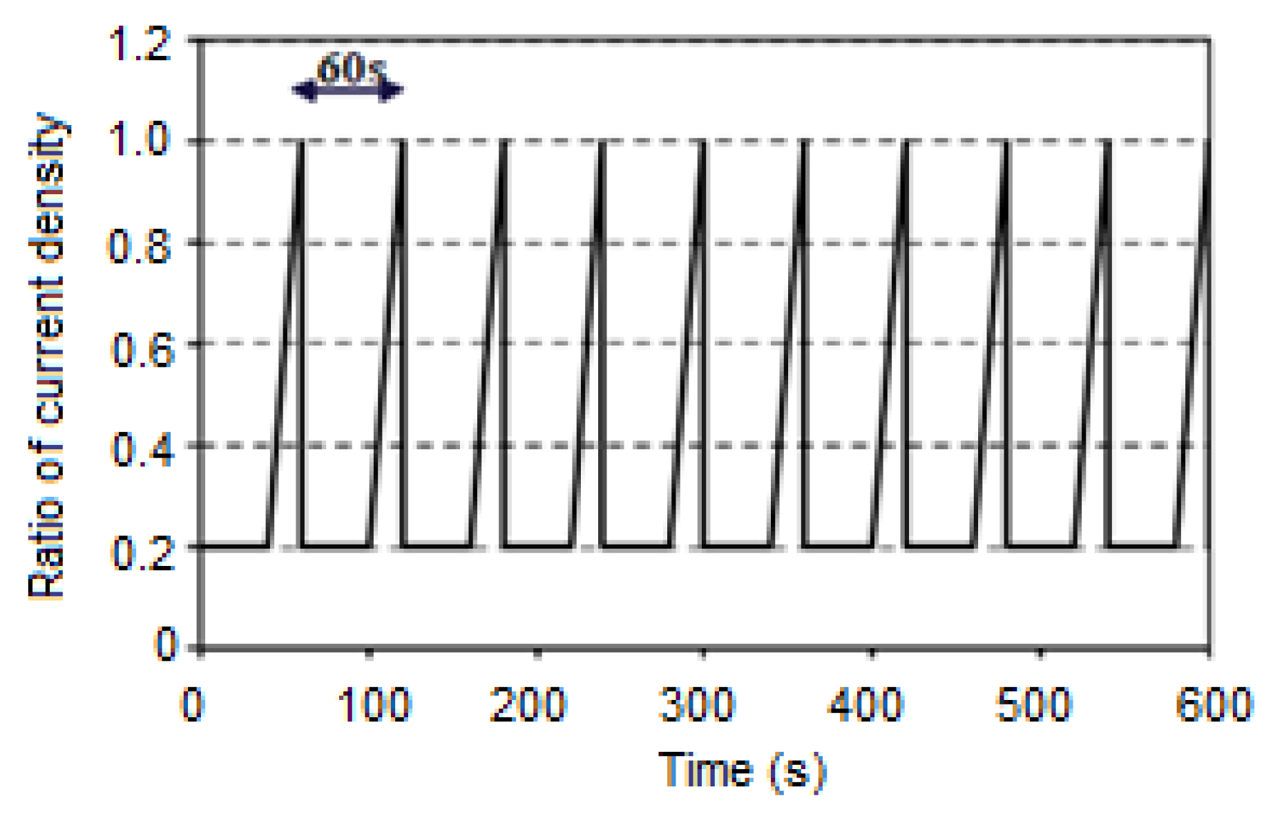
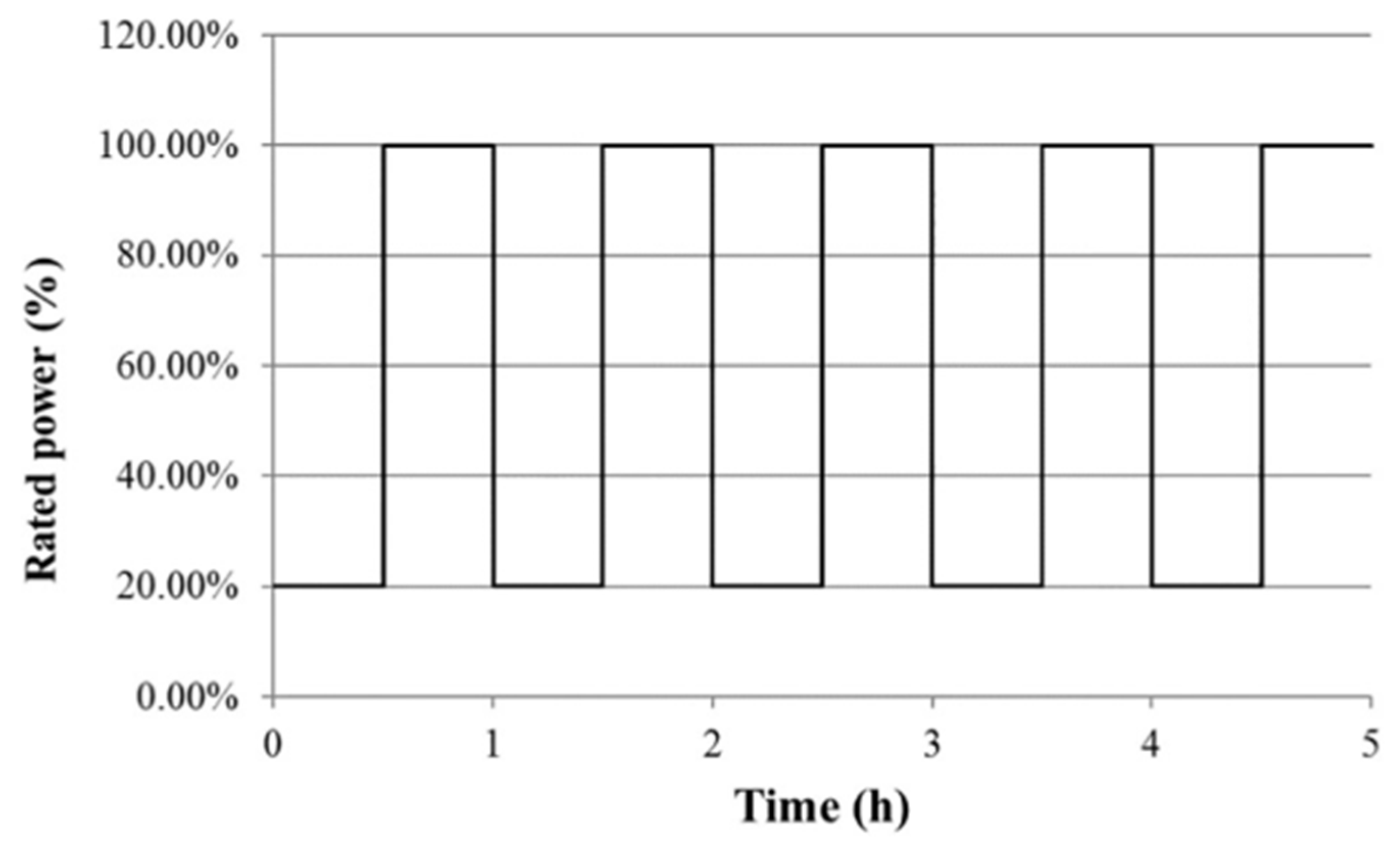
The FCTESTNET of the Fuel Cell Testing and Standardization Network (FC TestNet) was developed based on cycling conditions with current density following a dynamic profile versus time to determine the evolution of the voltage of a PEMFC single cell operating in specified conditions during a durability test [132]. This protocol is specifically designed for transportation applications since the load profile as defined is an adaptation of the type of power profiles defined for different vehicles, including power levels varying with dynamic variation. Two similar durability protocols were proposed based on different assumptions, a smooth power increase followed by power-off (Figure 5) and on-off cycling (Figure 6) [133].
As can be seen in Figure 5, the whole duration of one cycle of this protocol is 60 s, including the alternative operation of low-power stationary phase (40 s at i@ 20% Pmax A/cm²) and high-power dynamic phase (20 s with an increase of i from iload min @ 20% Pmax to Iload max @ 100% Pmax A/cm²). Pmax is defined here as the maximum power to be used during regular operation. The dynamic cycling phase is conducted after an initial polarization curve and followed by a final polarization curve. The comparison of these two polarization curves will be used to quantify the performance loss of the cell for the entire range of current density, allowing us to analyze the causes of performance degradation.
The other protocol was proposed by a collaboration of the IEC and FC TestNet, as shown in Figure 6 [119]. One cycle of this protocol lasts 3600 s, comprising the 1800 s alternative operation, full power condition, and 1800 s partial power condition. As illustrated in Figure 6, this protocol is similar FCTT. Both protocols merely switch between two types of normal operational conditions, ignoring all other scenarios. The distinction is that the specific operating conditions addressed in this protocol are full power and partial power. In addition, this protocol has greater cycle durations than the FCTT. This protocol primarily studies the durability of a PEMFC stack that switches between two operating modes (full power and partial power), making it appropriate for vehicles like city buses [4].

3.1.6. The Giantleap Protocol

Giantleap from the Fuel Cell and Hydrogen Joint Undertaking (FCH) was focused on using passenger-car fuel cell stacks and automotive balance of plant components in intercity buses. This protocol was proposed based on a dynamic load cycle for endurance testing and can be carried out in both single cells as well as in stacks. A detailed description of the Giantleap protocol is given in [134].
The cycle involves a two-hour cycle that begins with a short duration at OCV and a very gradual ramp-up rate (0.04 A·cm−2·s−1) to achieve high-efficiency operation. A 650 s length at a high-efficiency process is followed by an extra-long length at a steady state nominal operation (2500 s). Gas flow rates should be changed at least 3 s before ramping up the load and 3 s after ramping down the load to preserve a strategic operation from gas starvation. Furthermore, continuous current for long periods of time can cause some degradation (reversible degradation). As a result, the protocol includes some dynamics, moving back to high-efficiency operation for 650 s and then back to high-power operation for another 2500 s. The stack (or the cell in single-cell testing) power is ramped down at the same rate as the ramp-up rate after the steady-state cycles. The stack is placed into idling mode for 420 s after a brief time of 10 s at OCV.
For the fuel cell system to be used in the Giantleap project, the Giantleap protocol was specifically proposed, with the operating conditions shown in Table 5. It is strongly advised that the working conditions be tailored to the particular fuel cell technology and application of the manufacturer.

3.1.7. The Japanese JC08 Cycle

The JC08 protocol of Japan was first introduced by Japanese emission regulation authorities in 2005 for light vehicles (<3500 kg GVW) [135]; it was implemented officially in stages from October 2007 [136] and then formally proposed in October 2015, replacing the previous 11 and 10–15 protocols [4]. This protocol was initially used for emission measurement and fuel economy determination for internal combustion engine vehicles (e.g., gasoline and diesel vehicles) [135]. However, it has always been used to test PEMFC stack durability in hybrid cars [128,137]. It represents driving in congested traffic in Japanese cities, including idling periods and frequently alternating acceleration and deceleration.
For fuel efficiency measurement under the new fuel efficiency standards, the JC08 mode is used as a driving mode, consistent with the exhaust emission measurement method, and evaluates fuel performance more accurately [92]. Cold-start driving before the engine has warmed up, as well as hot-start driving after the engine has warmed up, are used to mimic real driving as closely as possible. A cold start and a warm start are used in the JC08 measurement.
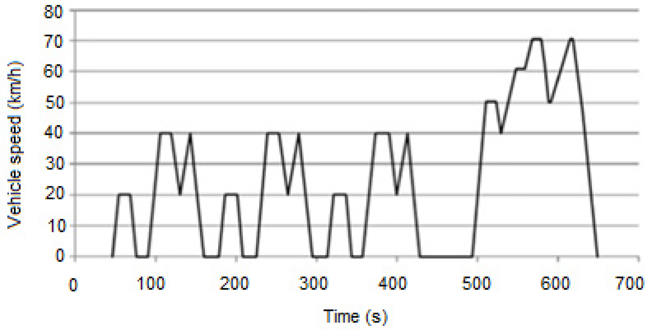
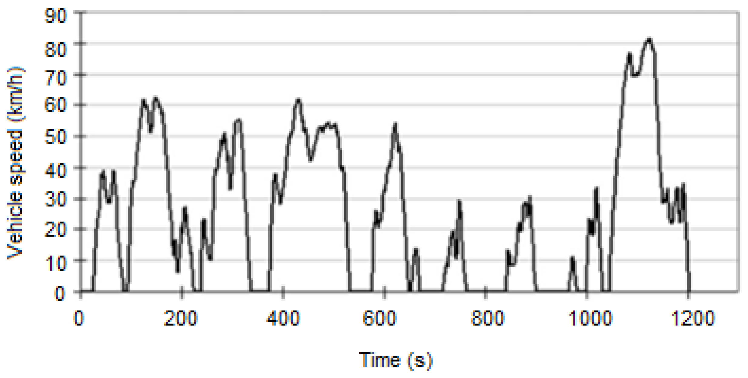
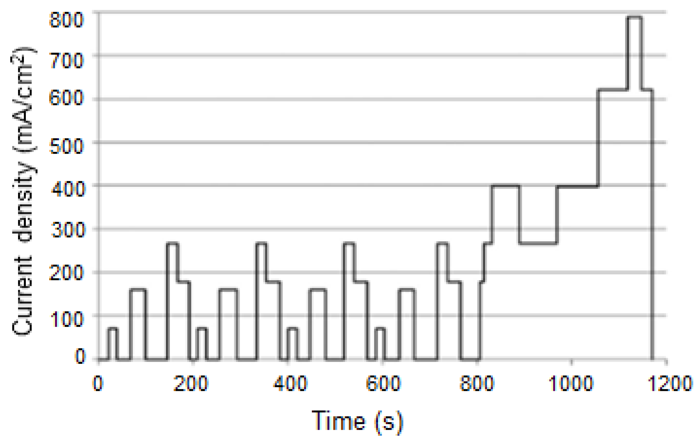
As shown in Figure 7 and Figure 8, the entire test in 10–15 mode takes 660 s, while the JC08 takes twice as long, at 1200 s. The total test distance in JC08 mode is 8.171 km, with an average test speed of 24.4 km per hour (including idling time) [135,136]. The rising and falling edges of the curve appear more frequently in the JC08 (total 26 times) than in the 10–15 mode, indicating that the JC08 frequently simulates the dynamic loading state. This indicates that the protocol closely resembles real-world driving conditions on city streets. In addition, the time for driving at a constant speed has been reduced, simulating the situation of constantly getting on and off the accelerator. Additionally, before being completely baked, a vehicle’s average speed is held at 50 km/h, simulating waiting for traffic lights in city driving. Furthermore, slight oscillations between 700 and 1000 s can be used as emergency braking. Finally, after hitting a top speed of 82 km/h, the car encountered a brief moment of vibration, simulating the condition of driving on non-urban highways [4,136]. JC08 is somewhat close to real driving conditions due to all of the urban and extra-urban driving scenarios used in the protocol. As a result, many automakers have used it in recent years to measure the reliability of their own PEMFC and hybrid vehicles [4].

3.1.8. Test Protocols in China

PEMFC durability test protocols were developed by leading universities and institutes in research PEMFC technology in China, including Tsinghua University, Tongji University, the Dalian Institute of Chemical Physics, and Wuhan University of Technology [138]. These protocols were intensively summarized in [4].
Tongji University’s test protocol was based on the NEDC and took into account real-world operating conditions. The protocol, like the NEDC, encompasses a wide range of real-world driving scenarios, including startup-shutdown, idling, partial power, full power, overload, and dynamic load running. The protocol lasts 1200 s, as shown in Figure 9 In this protocol, the operating conditions are mostly the same as in the NEDC. The fuel gas and oxidation gas inlets, on the other hand, are fully humidified [4].
Tsinghua University proposed a durability test protocol based on a typical Chinese bus driving cycle, which is divided into two phases as shown in Figure 10 Idling, dynamic load, and partial power running are all part of stage I; full power and overload running are part of phase II. Four phases I and one phase II make up a single driving cycle, with a high proportion of idling and full power conditions. The total length of this protocol is 7235 s, with 38.9% idling and 28.2% full power, similar to city bus driving characteristics. It demonstrates that this protocol can be used to evaluate the PEMFC city bus [4].
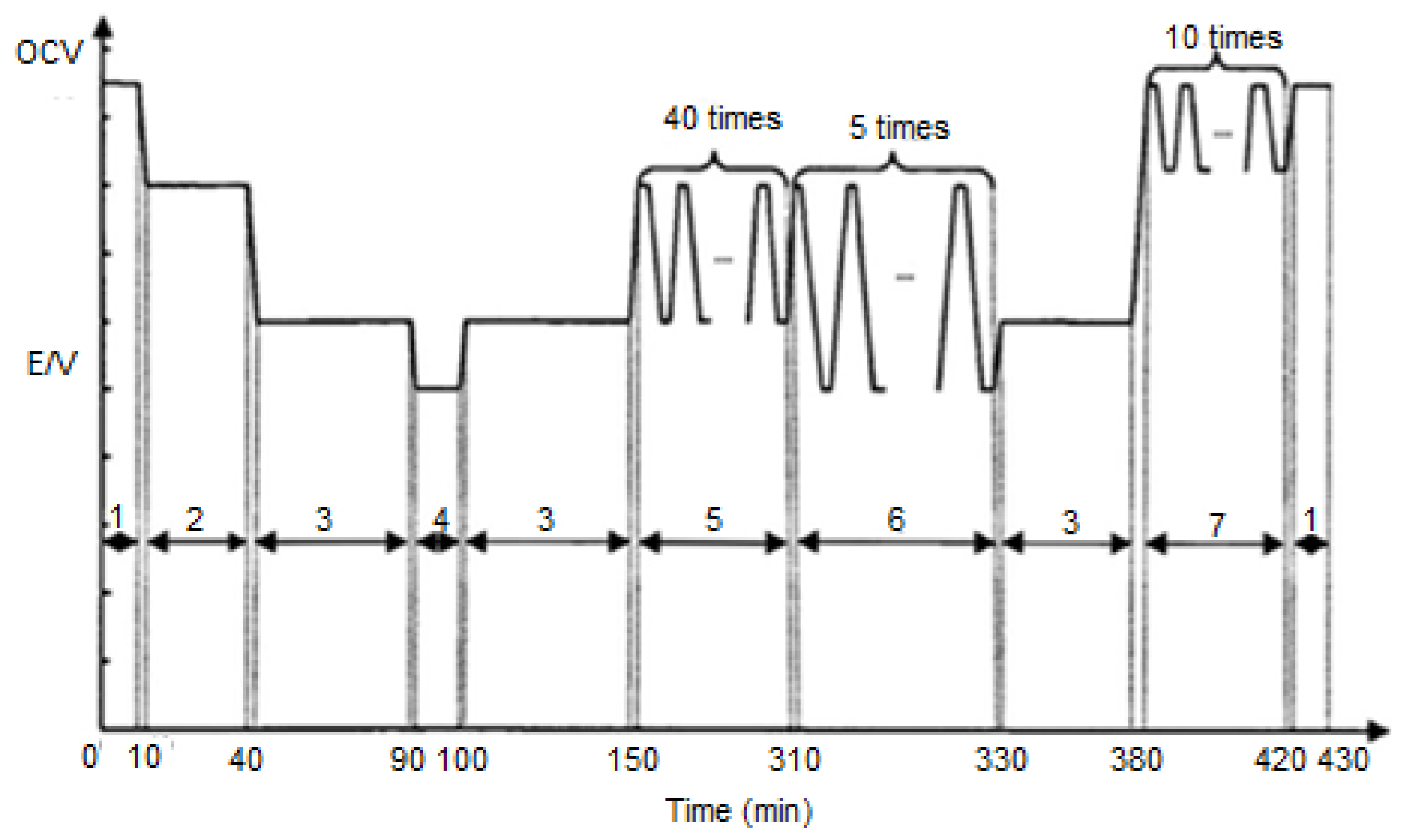
The Wuhan University of Technology’s test protocol is shown in Figure 11. This protocol was proposed to reveal the dominant impacts on PEMFC durability based on normal operating conditions in the actual driving process. The total length of this protocol is 25,800 s (430 min), which includes OCV, idling, dynamic load with RH cycling, full power, and overload. This protocol includes a large time portion for the dynamic load condition to represent the primary operating condition of PEMFCs in real-world road conditions. Aside from that, this load period includes RH cycling. Combining the two requirements helps the model to represent lifetime shift circumstances quicker, making it more suitable for daily-used PEMFC car durability and hybrid PEMFC car durability on city roads [4].
Centered on the Fuel Cell Engine (FCE) testing mode, the Dalian Institute of Chemical Physics developed a protocol for testing PEMFC stability under significantly severe operating conditions, as shown in Figure 12. The total length of this protocol is 5700 s (95 min), which includes idling, partial power, full power, and overload conditions. This protocol simulates the theoretical PEMFC stack operation (startup–incremental loading–full power running–overload running–shutdown) without the use of a dynamic load. The 20 min of idling operation is a demanding test for the fuel cell. The idling situation is a severe test of the PEMFC’s adaptability due to the relatively low stack working temperature and relatively high temperature at the air inlet [4].
Most of the standard operating conditions of actual driving actions are covered by the above test protocols, including startup-shutdown, idling, partial power running, full power running, overload running, and dynamic load running. The only difference, as shown in Table 6, is the length of each operation condition in the cycle [4].

3.1.9. Summary

The key feature of fuel cells in vehicular applications is load cycling. A fuel cell’s ability to operate successfully is determined not only by its efficiency but also by its durability. Endurance testing is used to assess fuel cell durability, which involves applying a repeated load profile to the cell and calculating performance degradation in terms of cell voltage decrease as a function of operating hours. To determine the cell/stack degradation rate, protocols based on a dynamic load cycle for endurance testing were proposed. An example of a PEMFC stack long-term durability experiment is illustrated in Figure 13.
According to a review of protocols from various organizations, institutions, and institutes around the world, a systematic and useful durability test protocol for PEMFC cells, stacks, and systems for vehicles should represent real-world driving conditions. Startup/shutdown, idling operation, partial power operation, full power operation, overload operation, and dynamic load operation are examples of these situations. According to tests and various driving conditions, the time portion of each condition in the entire cycle can be changed. To more comprehensively simulate the driving situation of PEMFC vehicles on actual roads, the dynamic load condition for light-duty vehicles should be planned and arranged with a large portion of the total length. A protocol, on the other hand, consists of a significant portion of idling and steady service, making it ideal for city buses [4]. The applicable vehicle types of PEMFC durability test protocols are summarized in Table 7.

3.2. Test Protocols for Stationary Applications

The effects of long-term operation on cell/stack performance in terms of voltage decay rate as a function of operating hours are investigated in aging or durability tests for PEMFCs. In general, there are two types of durability tests for stationary applications: steady-state durability tests and load cycling durability tests.

3.2.1. Steady-State Durability Tests

For stationary applications, the majority of long-term lifetime experiments are carried out under steady-state conditions (constant voltage or constant current) for long periods of time, often up to several thousand hours [1,2]. In terms of durability, the DOE developed steady-state protocols under constant current density and compared them to DOE targets. The cell will be run at a current density that produces 25% maximum power under stable operating conditions such as temperature, pressure, and stoichiometry. Except for in situ periodic diagnostic testing (every 200–250 h), the testing will be continuous [119]. Diagnostic testing aims to characterize variations in fundamental properties such as polarization curves, membrane resistance, hydrogen crossover, and electrochemical surface area as a function of time [1].
A test module of FCTESTNET was proposed for a long-term durability steady test under constant current density for a single PEMFC. The aim of the module was to figure out how a PEFC single cell’s voltage changed over time during a long-term durability test, which was mostly done in steady operation at a fixed current density but also included recurrent polarization curves to qualify the cell’s output at set intervals during the test. The polarization curves will be run at fixed intervals of tmax/10, where tmax is the maximum period of the test as specified by the particular objective of the test module. Depending on the operating conditions and the program, tmax can be set anywhere between 500 and 10,000 h. The final polarization curve will be compared to the initial one to qualify the cell’s performance loss over the entire range of current density and to investigate the causes of performance degradation, if any. Unless there is another ending criterion, such as specifying the test stop if the cell voltage falls below a pre-defined minimum voltage, the long-term durability test length would be tmax. If the components under examination are to be used for further testing, a minimum voltage of 0.5 V is recommended, and 0.3 V is recommended for research purposes, such as qualifying the lifetime and researching degradation processes to prevent irreversible harm to cell components [139].
In recent years, the STACKTEST project (European Development of PEM Fuel Cell Stack Reference Test Procedures for Industry) identified and validated the industrially applicable generic test modules [140,141]. A constant load durability test module [120] was introduced for stationary applications, with specific test input parameters shown in Table 8. Under continuous operation load, a model was used to assess the irreversible voltage decay rate induced by specific operating parameters. Throughout the test, a specific set of operating conditions was maintained, and the stack voltage and individual cell voltages were reported as functions of time. Aside from that, for MEA integrity reasons, the minimum single cell voltage limit should be set no lower than 0.3 V to avoid stack harm.

3.2.2. Load Cycling Durability Tests

As opposed to keeping the load constant, load cycling will put a strain on the catalyst, membrane, and carbon support materials. Typically, load cycling testing is done by cycling the stack current and recording the voltage responses. The duty cycle for stationary systems can vary depending on the applications (residential CHP, commercial power, stand-alone, or grid-connected). Cycling is supposed to be much less severe than transportation applications. With fewer on-off cycles and less time spent at OCV, start-up and transient operation would be easier [119].
While FCTESTNET’s dynamic load cycling was created specifically for transportation applications, it can also be used to assess the generic performance of PEMFCs [132]. The dynamic load cycling consists of a low power stationary step at I = 0.2i@ 20% Pmax, followed by a ramp from Iload min @ 20% Pmax to Iload max @ 100% Pmax. The total time of the test, tmax, is set between 500 and 10,000 h, and the interval is interrupted every tmax/10 h to record a polarization curve [120, 132]. The duration of the long-term durability test is determined in the same way as the steady test module.
The load-cycling durability test module was also added to the STACKTEST project with the goal of determining the effect of dynamic load changes on the irreversible performance loss of a fuel cell stack [142,143,144]. It is possible to use it to build a load profile. Figure 14 depicts an example load cycling profile for CHP systems. Extended profile times of up to 24 h, as well as long phase times, are characteristics of load profiles for stationary applications. The load profile shown is made up of nine stages, each with its own dwell time and stack load value. Since reformate-fuel gas is commonly used in CHP systems, the fuel gas composition should be simulated. If no other options are available, the composition can be set to: 30% CO2, 5% CH4, and 10 ppm of CO are added to hydrogen. It may use an extra moderate air bleed of 0.8% [144].

4. Conclusions

One of the most significant barriers to fuel cell commercialization is durability, as discussed in this review article. We present some of the most important factors influencing the long-term durability of PEMFCs in this study. Degradation of PEMFC materials, operating conditions, water control, and thermal management are among these factors. We discuss PEMFC durability test protocols for transportation applications developed by leading organizations, institutes, and universities around the world, such as the DOE, FCHEA, USDRIVE, UNECE, FC TestNet, IEC, and Japanese NEDO and Chinese universities including Tongji University, Tsinghua University, Wuhan University of Technology, and the Dalian Institute of Chemical Physics. These protocols were created to mimic real-world driving situations. However, they are not meant to be comprehensive for all driving situations encountered in the real world, such as long periods of idling due to traffic jams, etc. Researchers must make adjustments to adapt current operating conditions to test objectives. In addition, the protocols for reliability testing PEMFC stationary applications are briefly discussed. We hope that the results of this research will help to speed up the commercialization of PEMFCs.

Author Contributions

H.L.N.: Conceptualization, Methodology, Writing-Original draft preparation. J.H.: Resources, Writing—Original draft preparation. X.L.N.: Resources, Writing—Original draft preparation. S.Y.: Supervision. Y.-M.G.: Writing—Reviewing and Editing. D.D.L.: Writing—Reviewing and Editing. All authors have read and agreed to the published version of the manuscript.

Funding

This work was partly supported by the Korea Institute of Energy Technology Evaluation and Planning (KETEP) grant (No. 20203010030010) and by the Technology Innovation Program (No.10084611) funded By the Ministry of Trade, Industry and Energy (MOTIE, Korea).

Conflicts of Interest

The authors declare no conflict of interest.

References

  1. Yuan, X.Z.; Li, H.; Zhang, S.; Martin, J.; Wang, H. A review of polymer electrolyte membrane fuel cell durability test protocols. J. Power Sources 2011, 196, 9107–9116. [Google Scholar] [CrossRef] [Green Version]
  2. Borup, R.; Meyers, J.; Pivovar, B.; Kim, Y.S.; Mukundan, R.; Garland, N.; Myers, D.; Wilson, M.; Garzon, F.; Wood, D.; et al. Scientific aspects of polymer electrolyte fuel cell durability and degradation. Chem. Rev. 2007, 107, 3904–3951. [Google Scholar] [CrossRef] [PubMed]
  3. Borup, R.L.; Davey, J.R.; Garzon, F.H.; Wood, D.L.; Welch, P.M.; More, K. Polymer electrolyte membrane (PEM) fuel cell durability. In Materials Research Highlight, LALP-06-108; Los Alamos National Laboratory: Los Alamos, NM, USA, 2006. [Google Scholar]
  4. Chen, H.; Song, Z.; Zhao, X.; Zhang, T.; Pei, P.; Liang, C. A review of durability test protocols of the proton exchange membrane fuel cells for vehicle. Appl. Energy 2018, 224, 289–299. [Google Scholar] [CrossRef]
  5. Schmittinger, W.; Vahidi, A. A review of the main parameters influencing long-term performance and durability of PEM fuel cells. J. Power Sources 2008, 180, 1–14. [Google Scholar] [CrossRef]
  6. Stationary PEM Fuel Cells with Lifetimes beyond Five Years. Available online: https://cordis.europa.eu/project/id/256721 (accessed on 1 February 2021).
  7. Fuel Cells Section. In Multi-Year Research, Development, and Demonstartion Plan; U.S. Department of Energy: Washington, DC, USA, 2015; pp. 1–58.
  8. Fuel Cell Technical Team Roadmap. Available online: https://www.energy.gov/sites/prod/files/2017/11/f46/FCTT_Roadmap_Nov_2017_FINAL.pdf (accessed on 1 February 2021).
  9. Bloom, I.; Basco, J.K.; Walker, L.K.; Malkow, T.; DeMarco, G.; Saturnio, A.; Tsotridis, G. Fuel Cell Testing Protocols: An International Perspective, Joint ANL-JRC Scientific and Technical Report; Argonne National Laboratory: Argonne, IL, USA, 2013. [Google Scholar]
  10. U.S. Department of Transportation. Fuel Cells for Transportation Applications; Report No. FTA-TRI-IL-26-7006-2009.1; U.S. Department of Transportation: Washington, DC, USA, 2009.
  11. Wargo, E.A.; Dennison, C.R.; Kumbur, E.C. Durability of Polymer Electrolyte Fuel Cells: Status and Targets; Elsevier Inc.: Amsterdam, The Netherlands, 2012; ISBN 9780123869364. [Google Scholar]
  12. Büchi, F.N.; Inaba, M.; Schmidt, T.J. Polymer Electrolyte Fuel Cell Durability; Springer: Berlin/Heidelberg, Germany, 2009; ISBN 9780128114599. [Google Scholar]
  13. Fuel Cells and Hydrogen Joint Undertaking Programme Review Report; FCH-JU Programme Office: Brussels, Belgium, 2018; ISBN 9789292461362.
  14. Spernjak, D.; Fairweather, J.; Mukundan, R.; Rockward, T.; Borup, R.L. Influence of the microporous layer on carbon corrosion in the catalyst layer of a polymer electrolyte membrane fuel cell. J. Power Sources 2012, 214, 386–398. [Google Scholar] [CrossRef]
  15. Messing, M.; Kjeang, E. Empirical modeling of cathode electrode durability in polymer electrolyte fuel cells. J. Power Sources 2020, 451, 227750. [Google Scholar] [CrossRef]
  16. Kocha, S.S. Electrochemical Degradation: Electrocatalyst and Support Durability; Elsevier Inc.: Amsterdam, The Netherlands, 2011; ISBN 9780123869364. [Google Scholar]
  17. Jouin, M.; Gouriveau, R.; Hissel, D.; Péra, M.C.; Zerhouni, N. Degradations analysis and aging modeling for health assessment and prognostics of PEMFC. Reliab. Eng. Syst. Saf. 2016, 148, 78–95. [Google Scholar] [CrossRef]
  18. Zhang, S.; Yuan, X.Z.; Hin, J.N.C.; Wang, H.; Friedrich, K.A.; Schulze, M. A review of platinum-based catalyst layer degradation in proton exchange membrane fuel cells. J. Power Sources 2009, 194, 588–600. [Google Scholar] [CrossRef]
  19. Wu, J.; Yuan, X.Z.; Martin, J.J.; Wang, H.; Zhang, J.; Shen, J.; Wu, S.; Merida, W. A review of PEM fuel cell durability: Degradation mechanisms and mitigation strategies. J. Power Sources 2008, 184, 104–119. [Google Scholar] [CrossRef]
  20. Borup, R.L.; Davey, J.R.; Garzon, F.H.; Wood, D.L.; Inbody, M.A. PEM fuel cell electrocatalyst durability measurements. J. Power Sources 2006, 163, 76–81. [Google Scholar] [CrossRef]
  21. Dhanushkodi, S.R.; Tam, M.; Kundu, S.; Fowler, M.W.; Pritzker, M.D. Carbon corrosion fingerprint development and de-convolution of performance loss according to degradation mechanism in PEM fuel cells. J. Power Sources 2013, 240, 114–121. [Google Scholar] [CrossRef]
  22. Sasaki, K.; Shao, M.; Adzic, R. Dissolution and stabilization of platinum in oxygen cathodes. Polym. Electrolyte Fuel Cell Durab. 2009, 7–27. [Google Scholar] [CrossRef]
  23. Wang, X.; Kumar, R.; Myers, D.J. Effect of voltage on platinum dissolution relevance to polymer electrolyte fuel cells. Electrochem. Solid-State Lett. 2006, 9, 225–227. [Google Scholar] [CrossRef]
  24. Ota, K.; Koizumi, Y. Platinum dissolution models and voltage cycling effects: Platinum dissolution in polymer electrolyte fuel cell (PEFC) and low-temperature fuel cells. Handb. Fuel Cells 2010, 1–7. [Google Scholar] [CrossRef]
  25. Harzer, G.S.; Schwämmlein, J.N.; Damjanović, A.M.; Ghosh, S.; Gasteiger, H.A. Cathode Loading Impact on Voltage Cycling Induced PEMFC Degradation: A Voltage Loss Analysis. J. Electrochem. Soc. 2018, 165, F3118–F3131. [Google Scholar] [CrossRef] [Green Version]
  26. Albarbar, A.; Alrweq, M. Proton Exchange Membrane Fuel Cells: Design, Modelling and Performance Assessment Techniques; Springer: Berlin/Heidelberg, Germany, 2017; ISBN 9783319707273. [Google Scholar]
  27. Andrew, L.; Dicks, D.A.J.R. Fuel Cell Systems Explained, 3rd ed.; John Wiley & Sons Ltd.: Hoboken, NJ, USA, 2018; ISBN 9788578110796. [Google Scholar]
  28. Chandesris, M.; Vincent, R.; Guetaz, L.; Roch, J.S.; Thoby, D.; Quinaud, M. Membrane degradation in PEM fuel cells: From experimental results to semi-empirical degradation laws. Int. J. Hydrogen Energy 2017, 42, 8139–8149. [Google Scholar] [CrossRef]
  29. Bhattacharya, S.; Leung, J.; Lauritzen, M.V.; Kjeang, E. Isolated chemical degradation induced decay of mechanical membrane properties in fuel cells. Electrochim. Acta 2020, 352, 136489. [Google Scholar] [CrossRef]
  30. Danilczuk, M.; Lancucki, L.; Schlick, S.; Hamrock, S.J.; Haugen, G.M. In-depth profiling of degradation processes in a fuel cell: 2D spectral-spatial FTIR spectra of nafion membranes. ACS Macro Lett. 2012, 1, 280–285. [Google Scholar] [CrossRef]
  31. De Moor, G.; Bas, C.; Charvin, N.; Dillet, J.; Maranzana, G.; Lottin, O.; Caqué, N.; Rossinot, E.; Flandin, L. Perfluorosulfonic acid membrane degradation in the hydrogen inlet region: A macroscopic approach. Int. J. Hydrogen Energy 2016, 41, 483–496. [Google Scholar] [CrossRef]
  32. Liu, W.; Crum, M. Effective Testing Matrix for Studying Membrane Durability in PEM Fuel Cells: Part I. Chemical Durability. ECS Trans. 2006, 3, 531–540. [Google Scholar] [CrossRef]
  33. LaConti, A.B.; Hamdan, M.; McDonald, R.C. Mechanisms of membrane degradation. Handb. Fuel Cells 2010, 584, 1700–1712. [Google Scholar] [CrossRef]
  34. Qiu, D.; Peng, L.; Liang, P.; Yi, P.; Lai, X. Mechanical degradation of proton exchange membrane along the MEA frame in proton exchange membrane fuel cells. Energy 2018, 165, 210–222. [Google Scholar] [CrossRef]
  35. Subianto, S.; Pica, M.; Casciola, M.; Cojocaru, P.; Merlo, L.; Hards, G.; Jones, D.J. Physical and chemical modification routes leading to improved mechanical properties of perfluorosulfonic acid membranes for PEM fuel cells. J. Power Sources 2013, 233, 216–230. [Google Scholar] [CrossRef]
  36. Schiraldi, D.A. Perfluorinated polymer electrolyte membrane durability. Polym. Rev. 2006, 46, 315–327. [Google Scholar] [CrossRef]
  37. Ferreira, R.B.; Falcão, D.S.; Pinto, A.M.F.R. Simulation of membrane chemical degradation in a proton exchange membrane fuel cell by computational fluid dynamics. Int. J. Hydrogen Energy 2020, 6, 1106–1120. [Google Scholar] [CrossRef]
  38. Kundu, S.; Fowler, M.W.; Simon, L.C.; Abouatallah, R.; Beydokhti, N. Degradation analysis and modeling of reinforced catalyst coated membranes operated under OCV conditions. J. Power Sources 2008, 183, 619–628. [Google Scholar] [CrossRef]
  39. Oshiba, Y.; Kosaka, M.; Yamaguchi, T. Chemical durability of thin pore-filling membrane in open-circuit voltage hold test. Int. J. Hydrogen Energy 2019, 44, 28996–29001. [Google Scholar] [CrossRef]
  40. Zhao, J.; Li, X. A review of polymer electrolyte membrane fuel cell durability for vehicular applications: Degradation modes and experimental techniques. Energy Convers. Manag. 2019, 199, 112022. [Google Scholar] [CrossRef]
  41. Yuan, X.Z.; Zhang, S.; Ban, S.; Huang, C.; Wang, H.; Singara, V.; Fowler, M.; Schulze, M.; Haug, A.; Andreas Friedrich, K.; et al. Degradation of a PEM fuel cell stack with Nafion® membranes of different thicknesses. Part II: Ex situ diagnosis. J. Power Sources 2012, 205, 324–334. [Google Scholar] [CrossRef] [Green Version]
  42. Lim, C.; Ghassemzadeh, L.; Van Hove, F.; Lauritzen, M.; Kolodziej, J.; Wang, G.G.; Holdcroft, S.; Kjeang, E. Membrane degradation during combined chemical and mechanical accelerated stress testing of polymer electrolyte fuel cells. J. Power Sources 2014, 257, 102–110. [Google Scholar] [CrossRef]
  43. Wang, C.; Zhang, J.; Wang, S.; Hao, S.; Li, J.; Mao, Z.; Mao, Z.; Ouyang, M.; Liu, Z. Degradation study of Membrane Electrode Assembly with PTFE/Nafion composite membrane utilizing accelerated stress technique. Int. J. Hydrogen Energy 2016, 41, 16212–16219. [Google Scholar] [CrossRef]
  44. Sun, X.; Shi, S.; Fu, Y.; Chen, J.; Lin, Q.; Hu, J.; Li, C.; Li, J.; Chen, X. Embrittlement induced fracture behavior and mechanisms of perfluorosulfonic-acid membranes after chemical degradation. J. Power Sources 2020, 453, 227893. [Google Scholar] [CrossRef]
  45. Wu, B.; Zhao, M.; Shi, W.; Liu, W.; Liu, J.; Xing, D.; Yao, Y.; Hou, Z.; Ming, P.; Gu, J.; et al. The degradation study of Nafion/PTFE composite membrane in PEM fuel cell under accelerated stress tests. Int. J. Hydrogen Energy 2014, 39, 14381–14390. [Google Scholar] [CrossRef]
  46. Quiroga, M.A.; Malek, K.; Franco, A.A. A Multiparadigm Modeling Investigation of Membrane Chemical Degradation in PEM Fuel Cells. J. Electrochem. Soc. 2016, 163, F59–F70. [Google Scholar] [CrossRef] [Green Version]
  47. Ozden, A.; Shahgaldi, S.; Li, X.; Hamdullahpur, F. A review of gas diffusion layers for proton exchange membrane fuel cells—With a focus on characteristics, characterization techniques, materials and designs. Prog. Energy Combust. Sci. 2019, 74, 50–102. [Google Scholar] [CrossRef]
  48. Park, J.; Oh, H.; Ha, T.; Lee, Y.I.; Min, K. A review of the gas diffusion layer in proton exchange membrane fuel cells: Durability and degradation. Appl. Energy 2015, 155, 866–880. [Google Scholar] [CrossRef]
  49. El-kharouf, A.; Pollet, B.G. Gas Diffusion Media and Their Degradation; Elsevier Inc.: Amsterdam, The Netherlands, 2012; ISBN 9780123869364. [Google Scholar]
  50. Lapicque, F.; Belhadj, M.; Bonnet, C.; Pauchet, J.; Thomas, Y. A critical review on gas diffusion micro and macroporous layers degradations for improved membrane fuel cell durability. J. Power Sources 2016, 336, 40–53. [Google Scholar] [CrossRef]
  51. Taherian, R. Applications of Polymer Based Composites: Gas Diffusion Layer of Pem Fuel Cells; Elsevier Inc.: Amsterdam, The Netherlands, 2018; ISBN 9780128125410. [Google Scholar]
  52. Yu, S.; Li, X.; Li, J.; Liu, S.; Lu, W.; Shao, Z.; Yi, B. Study on hydrophobicity degradation of gas diffusion layer in proton exchange membrane fuel cells. Energy Convers. Manag. 2013, 76, 301–306. [Google Scholar] [CrossRef]
  53. Toghyani, S.; Moradi Nafchi, F.; Afshari, E.; Hasanpour, K.; Baniasadi, E.; Atyabi, S.A. Thermal and electrochemical performance analysis of a proton exchange membrane fuel cell under assembly pressure on gas diffusion layer. Int. J. Hydrogen Energy 2018, 43, 4534–4545. [Google Scholar] [CrossRef]
  54. Tawfik, H.; Hung, Y.; Mahajan, D. Bipolar Plate Durability and Challenges; Elsevier Inc: Amsterdam, The Netherlands, 2012; ISBN 9780123869364. [Google Scholar]
  55. Yuan, X.Z.; Wang, H.; Zhang, J.; Wilkinson, D.P. Bipolar plates for PEM fuel cells—From materials to processing. J. New Mater. Electrochem. Syst. 2005, 8, 257–267. [Google Scholar]
  56. Hermann, A.; Chaudhuri, T.; Spagnol, P. Bipolar plates for PEM fuel cells: A review. Int. J. Hydrogen Energy 2005, 30, 1297–1302. [Google Scholar] [CrossRef]
  57. Shimpalee, S.; Lilavivat, V.; McCrabb, H.; Khunatorn, Y.; Lee, H.K.; Lee, W.K.; Weidner, J.W. Investigation of bipolar plate materials for proton exchange membrane fuel cells. Int. J. Hydrogen Energy 2016, 41, 13688–13696. [Google Scholar] [CrossRef] [Green Version]
  58. Cunningham, B.D.; Huang, J.; Baird, D.G. Review of materials and processing methods used in the production of bipolar plates for fuel cells. Int. Mater. Rev. 2007, 52, 1–13. [Google Scholar] [CrossRef]
  59. Li, X.; Sabir, I. Review of bipolar plates in PEM fuel cells: Flow-field designs. Int. J. Hydrogen Energy 2005, 30, 359–371. [Google Scholar] [CrossRef]
  60. Hartnig, C.; Schmidt, T.J. On a new degradation mode for high-temperature polymer electrolyte fuel cells: How bipolar plate degradation affects cell performance. Electrochim. Acta 2011, 56, 4237–4242. [Google Scholar] [CrossRef]
  61. Karimi, S.; Fraser, N.; Roberts, B.; Foulkes, F.R. A review of metallic bipolar plates for proton exchange membrane fuel cells: Materials and fabrication methods. Adv. Mater. Sci. Eng. 2012, 2012, 828070. [Google Scholar] [CrossRef] [Green Version]
  62. Kakati, B.K.; Ghosh, A.; Verma, A. Efficient composite bipolar plate reinforced with carbon fiber and graphene for proton exchange membrane fuel cell. Int. J. Hydrogen Energy 2013, 38, 9362–9369. [Google Scholar] [CrossRef]
  63. Adloo, A.; Sadeghi, M.; Masoomi, M.; Pazhooh, H.N. High performance polymeric bipolar plate based on polypropylene/graphite/graphene/nano-carbon black composites for PEM fuel cells. Renew. Energy 2016, 99, 867–874. [Google Scholar] [CrossRef]
  64. Yu, H.N.; Lim, J.W.; Kim, M.K.; Lee, D.G. Plasma treatment of the carbon fiber bipolar plate for PEM fuel cell. Compos. Struct. 2012, 94, 1911–1918. [Google Scholar] [CrossRef]
  65. Kang, K.; Park, S.; Jo, A.; Lee, K.; Ju, H. Development of ultralight and thin bipolar plates using epoxy-carbon fiber prepregs and graphite composites. Int. J. Hydrogen Energy 2017, 42, 1691–1697. [Google Scholar] [CrossRef]
  66. Kakati, B.K.; Sathiyamoorthy, D.; Verma, A. Electrochemical and mechanical behavior of carbon composite bipolar plate for fuel cell. Int. J. Hydrogen Energy 2010, 35, 4185–4194. [Google Scholar] [CrossRef]
  67. De Bruijn, F.A.; Dam, V.A.T.; Janssen, G.J.M. Review: Durability and degradation issues of PEM fuel cell components. Fuel Cells 2008, 8, 3–22. [Google Scholar] [CrossRef]
  68. Bi, F.; Hou, K.; Yi, P.; Peng, L.; Lai, X. Mechanisms of growth, properties and degradation of amorphous carbon films by closed field unbalanced magnetron sputtering on stainless steel bipolar plates for PEMFCs. Appl. Surf. Sci. 2017, 422, 921–931. [Google Scholar] [CrossRef]
  69. Pilinski, N.; Käding, C.; Dushina, A.; Hickmann, T.; Dyck, A.; Wagner, P. Investigation of corrosion methods for bipolar plates for high temperature polymer electrolyte membrane fuel cell application. Energies 2020, 13, 235. [Google Scholar] [CrossRef] [Green Version]
  70. Yan, W.M.; Chen, C.Y.; Liang, C.H. Comparison of performance degradation of high temperature PEM fuel cells with different bipolar plates. Energy 2019, 186, 115836. [Google Scholar] [CrossRef]
  71. Penga, Ž.; Radica, G.; Barbir, F.; Eckert, P. Giantleap Deliverable D1.3: Degradation Mechanisms in Automotive Fuel Cell Systems; FCH-JU Programme Office: Brussels, Belgium, 2017; p. 46. [Google Scholar]
  72. Gatto, I.; Urbani, F.; Giacoppo, G.; Barbera, O.; Passalacqua, E. Influence of the bolt torque on PEFC performance with different gasket materials. Int. J. Hydrogen Energy 2011, 36, 13043–13050. [Google Scholar] [CrossRef]
  73. Qiu, D.; Liang, P.; Peng, L.; Yi, P.; Lai, X.; Ni, J. Material behavior of rubber sealing for proton exchange membrane fuel cells. Int. J. Hydrogen Energy 2020, 45, 5465–5473. [Google Scholar] [CrossRef]
  74. Ye, D.H.; Zhan, Z.G. A review on the sealing structures of membrane electrode assembly of proton exchange membrane fuel cells. J. Power Sources 2013, 231, 285–292. [Google Scholar] [CrossRef]
  75. Bieringer, R.; Adler, M.; Geiss, S.; Viol, M. Gaskets: Important durability issues. In Polymer Electrolyte Fuel Cell Durability; Springer: New York, NY, USA, 2009; pp. 271–281. [Google Scholar] [CrossRef]
  76. Jake, S.; Jiang, K. Elastomer Application in Microsystem and Microfluidics. Adv. Elastomers Technol. Prop. Appl. 2012. [Google Scholar] [CrossRef] [Green Version]
  77. Tan, J.; Chao, Y.J.; Van Zee, J.W.; Lee, W.K. Degradation of elastomeric gasket materials in PEM fuel cells. Mater. Sci. Eng. A 2007, 445–446, 669–675. [Google Scholar] [CrossRef]
  78. Li, G.; Tan, J.; Gong, J. Degradation of the elastomeric gasket material in a simulated and four accelerated proton exchange membrane fuel cell environments. J. Power Sources 2012, 205, 244–251. [Google Scholar] [CrossRef]
  79. Husar, A.; Serra, M.; Kunusch, C. Description of gasket failure in a 7 cell PEMFC stack. J. Power Sources 2007, 169, 85–91. [Google Scholar] [CrossRef] [Green Version]
  80. Tan, J.; Chao, Y.J.; Yang, M.; Lee, W.K.; Van Zee, J.W. Chemical and mechanical stability of a Silicone gasket material exposed to PEM fuel cell environment. Int. J. Hydrogen Energy 2011, 36, 1846–1852. [Google Scholar] [CrossRef]
  81. Li, G.; Tan, J.; Gong, J. Chemical aging of the silicone rubber in a simulated and three accelerated proton exchange membrane fuel cell environments. J. Power Sources 2012, 217, 175–183. [Google Scholar] [CrossRef]
  82. Cui, T.; Chao, Y.J.; Van Zee, J.W. Sealing force prediction of elastomeric seal material for PEM fuel cell under temperature cycling. Int. J. Hydrogen Energy 2014, 39, 1430–1438. [Google Scholar] [CrossRef]
  83. Yang, D.; Ma, J.; Zhang, Q.; Li, B.; Ming, P.; Zhang, C. Accelerated Test of Silicone Rubbers Exposing to PEMFC environment. Prog. Nat. Sci. Mater. Int. 2020, 30, 882–889. [Google Scholar] [CrossRef]
  84. Tsotridis, G.; Pilenga, A.; De Marco, G.; Malkow, T. EU Harmonised Test Protocols for PEMFC MEA Testing in Single Cell Configuration for Automotive Applications; JRC Science for Policy Report; Join Research Centre: Petten, The Netherlands, 2015; ISBN 978-92-79-54132-2. [Google Scholar]
  85. Zhao, Y.; Mao, Y.; Zhang, W.; Tang, Y.; Wang, P. Reviews on the effects of contaminations and research methodologies for PEMFC. Int. J. Hydrogen Energy 2020, 45, 23174–23200. [Google Scholar] [CrossRef]
  86. Cheng, X.; Shi, Z.; Glass, N.; Zhang, L.; Zhang, J.; Song, D.; Liu, Z.S.; Wang, H.; Shen, J. A review of PEM hydrogen fuel cell contamination: Impacts, mechanisms, and mitigation. J. Power Sources 2007, 165, 739–756. [Google Scholar] [CrossRef]
  87. Jing, F.; Hou, M.; Shi, W.; Fu, J.; Yu, H.; Ming, P.; Yi, B. The effect of ambient contamination on PEMFC performance. J. Power Sources 2007, 166, 172–176. [Google Scholar] [CrossRef]
  88. Li, H.; Wang, H.; Qian, W.; Zhang, S.; Wessel, S.; Cheng, T.T.H.; Shen, J.; Wu, S. Chloride contamination effects on proton exchange membrane fuel cell performance and durability. J. Power Sources 2011, 196, 6249–6255. [Google Scholar] [CrossRef]
  89. Amamou, A.A.; Kelouwani, S.; Boulon, L.; Agbossou, K. A Comprehensive Review of Solutions and Strategies for Cold Start of Automotive Proton Exchange Membrane Fuel Cells. IEEE Access 2016, 4, 4989–5002. [Google Scholar] [CrossRef]
  90. Electron Microscope Analysis of Low Temperature Damage in PEM Fuel Cells. Available online: http://www2.optics.rochester.edu/workgroups/cml/opt307/spr05/eric/ (accessed on 1 February 2021).
  91. Yan, Q.; Toghiani, H.; Lee, Y.W.; Liang, K.; Causey, H. Effect of sub-freezing temperatures on a PEM fuel cell performance, startup and fuel cell components. J. Power Sources 2006, 160, 1242–1250. [Google Scholar] [CrossRef]
  92. Chen, H.; Zhao, X.; Zhang, T.; Pei, P. The reactant starvation of the proton exchange membrane fuel cells for vehicular applications: A review. Energy Convers. Manag. 2019, 182, 282–298. [Google Scholar] [CrossRef]
  93. Pei, P.; Chen, H. Main factors affecting the lifetime of Proton Exchange Membrane fuel cells in vehicle applications: A review. Appl. Energy 2014, 125, 60–75. [Google Scholar] [CrossRef]
  94. Lin, R.; Cui, X.; Shan, J.; Técher, L.; Xiong, F.; Zhang, Q. Investigating the effect of start-up and shut-down cycles on the performance of the proton exchange membrane fuel cell by segmented cell technology. Int. J. Hydrogen Energy 2015, 40, 14952–14962. [Google Scholar] [CrossRef]
  95. Sorrentino, A.; Sundmacher, K.; Vidakovic-Koch, T. Polymer Electrolyte Fuel Cell Degradation Mechanisms and Their Diagnosis by Frequency Response Analysis Methods: A Review. Energies 2020, 13, 5825. [Google Scholar] [CrossRef]
  96. Chang, Y.; Qin, Y.; Yin, Y.; Zhang, J.; Li, X. Humidification strategy for polymer electrolyte membrane fuel cells—A review. Appl. Energy 2018, 230, 643–662. [Google Scholar] [CrossRef]
  97. Sanchez, D.G.; Ruiu, T.; Biswas, I.; Schulze, M.; Helmly, S.; Friedrich, K.A. Local impact of humidification on degradation in polymer electrolyte fuel cells. J. Power Sources 2017, 352, 42–55. [Google Scholar] [CrossRef] [Green Version]
  98. Vengatesan, S.; Kim, H.J.; Lee, S.Y.; Cho, E.A.; Ha, H.Y.; Oh, I.H.; Lim, T.H. Operation of a proton exchange membrane fuel cell under non-humidified conditions using a membrane-electrode assemblies with composite membrane and electrode. J. Power Sources 2007, 167, 325–329. [Google Scholar] [CrossRef]
  99. Le Canut, J.-M.; Abouatallah, R.M.; Harrington, D.A. Detection of Membrane Drying, Fuel Cell Flooding, and Anode Catalyst Poisoning on PEMFC Stacks by Electrochemical Impedance Spectroscopy. J. Electrochem. Soc. 2006, 153, A857. [Google Scholar] [CrossRef]
  100. Zhang, C.; Li, W.; Hu, M.; Cheng, X.; He, K.; Mao, L. A Comparative Study of Using Polarization Curve Models in Proton Exchange Membrane Fuel Cell Degradation Analysis. Energies 2020, 13, 3759. [Google Scholar] [CrossRef]
  101. Authayanun, S.; Pothong, W.; Ngamsai, K.; Patniboon, A.; Arpornwichanop, A. Effect of water transport on the electrical performance of PEM fuel cell. Energy Procedia 2014, 61, 1553–1556. [Google Scholar] [CrossRef] [Green Version]
  102. Knights, S.D.; Colbow, K.M.; St-Pierre, J.; Wilkinson, D.P. Aging mechanisms and lifetime of PEFC and DMFC. J. Power Sources 2004, 127, 127–134. [Google Scholar] [CrossRef]
  103. Ji, M.; Wei, Z. A review of water management in polymer electrolyte membrane fuel cells. Energies 2009, 2, 1057–1106. [Google Scholar] [CrossRef] [Green Version]
  104. Bhattacharya, P.K. Water flooding in the proton exchange membrane fuel cell. Directions 2015, 15, 24–33. [Google Scholar]
  105. Nguyen, T.V.; White, R.E. A Water and Heat Management Model for Proton-Exchange-Membrane Fuel Cells. J. Electrochem. Soc. 1993, 140, 2178–2186. [Google Scholar] [CrossRef]
  106. Thangavelautham, J. Degradation in PEM Fuel Cells and Mitigation Strategies Using System Design and Control. Prot. Exch. Membr. Fuel Cell 2018. [Google Scholar] [CrossRef] [Green Version]
  107. He, W.; Lin, G.; Van Nguyen, T. Diagnostic Tool to Detect Electrode Flooding in Proton-Exchange Membrane Fuel Cells. AIChE J. 2003, 49, 3221–3228. [Google Scholar] [CrossRef]
  108. Wang, X.R.; Ma, Y.; Gao, J.; Li, T.; Jiang, G.Z.; Sun, Z.Y. Review on water management methods for proton exchange membrane fuel cells. Int. J. Hydrogen Energy 2020. [Google Scholar] [CrossRef]
  109. Hussaini, I.S.; Wang, C.Y. Visualization and quantification of cathode channel flooding in PEM fuel cells. J. Power Sources 2009, 187, 444–451. [Google Scholar] [CrossRef]
  110. Kim, M.; Jung, N.; Eom, K.; Yoo, S.J.; Kim, J.Y.; Jang, J.H.; Kim, H.J.; Hong, B.K.; Cho, E. Effects of anode flooding on the performance degradation of polymer electrolyte membrane fuel cells. J. Power Sources 2014, 266, 332–340. [Google Scholar] [CrossRef]
  111. Liu, X.; Guo, H.; Ye, F.; Ma, C.F. Water flooding and pressure drop characteristics in flow channels of proton exchange membrane fuel cells. Electrochim. Acta 2007, 52, 3607–3614. [Google Scholar] [CrossRef]
  112. Liu, Y.; Bai, S.; Wei, P.; Pei, P.; Yao, S.; Sun, H. Lowering the Pressure Drop and Cost of a Proton Exchange Membrane Fuel Cell by Flow Field Plate Design. Energy Fuels 2020, 34, 8857–8863. [Google Scholar] [CrossRef]
  113. Mishler, J.; Wang, Y.; Lujan, R.; Mukundan, R.; Borup, R.L. An Experimental Study of Polymer Electrolyte Fuel Cell Operation at Sub-Freezing Temperatures. J. Electrochem. Soc. 2013, 160, F514–F521. [Google Scholar] [CrossRef]
  114. Macauley, N.; Lujan, R.W.; Spernjak, D.; Hussey, D.S.; Jacobson, D.L.; More, K.; Borup, R.L.; Mukundan, R. Durability of Polymer Electrolyte Membrane Fuel Cells Operated at Subfreezing Temperatures. J. Electrochem. Soc. 2016, 163, F1317–F1329. [Google Scholar] [CrossRef] [Green Version]
  115. Gao, J.; Li, M.; Hu, Y.; Chen, H.; Ma, Y. Challenges and developments of automotive fuel cell hybrid power system and control. Sci. China Inf. Sci. 2019, 62, 1–25. [Google Scholar] [CrossRef] [Green Version]
  116. Barique, M.A.; Tsuchida, E.; Ohira, A.; Tashiro, K. Effect of Elevated Temperatures on the States of Water and Their Correlation with the Proton Conductivity of Nafion. ACS Omega 2017, 3, 349–360. [Google Scholar] [CrossRef] [PubMed] [Green Version]
  117. Bargal, M.H.S.; Abdelkareem, M.A.A.; Tao, Q.; Li, J.; Shi, J.; Wang, Y. Liquid cooling techniques in proton exchange membrane fuel cell stacks: A detailed survey. Alexandria Eng. J. 2020, 59, 635–655. [Google Scholar] [CrossRef]
  118. Jafri, N.H.; Gupta, S. An overview of Fuel Cells application in transportation. In Proceedings of the 2016 IEEE Transporation Electrification Conference and Expo, Asia-Pacific (ITEC), Busan, Korea, 1–4 June 2016; pp. 129–133. [Google Scholar] [CrossRef]
  119. Bloom, I.; Walker, L.K.; Basco, J.K.; Malkow, T.; Saturnio, A.; De Marco, G.; Tsotridis, G. A comparison of Fuel Cell Testing protocols—A case study: Protocols used by the U.S. Department of Energy, European Union, International Electrotechnical Commission/Fuel Cell Testing and Standardization Network, and Fuel Cell Technical Team. J. Power Sources 2013, 243, 451–457. [Google Scholar] [CrossRef]
  120. Fabrice MICOUD, S.R. (CEA) STACKTEST: WP5: International Standard Status Report; Fuel Cells and Hydrogen Joint Undertaking (FCH JU): Zentrum für Sonnenenergie- und Wasserstoff-Forschung Baden-Württemberg (ZSW): Ulm, Germany, 2013. [Google Scholar]
  121. Han, J.; Han, J.; Yu, S. Experimental analysis of performance degradation of 3-cell PEMFC stack under dynamic load cycle. Int. J. Hydrogen Energy 2020, 45, 13045–13054. [Google Scholar] [CrossRef]
  122. The Challenge for AUTOMAKERS—A More Stringent Test Procedure for EVs and HEVs. Available online: https://www.silicon-mobility.com/the-challenge-for-automakers-a-more-stringent-test-procedure-for-evs-and-hevs/ (accessed on 1 February 2021).
  123. WLTP: How It Will Change Road Tax and VRT in Ireland. Available online: https://www.irishevowners.ie/useful-info/wltp-how-it-will-change-road-tax-and-vrt-in-ireland/ (accessed on 1 February 2021).
  124. WLTP Explained: What Is WLTP and How Does It Work? Available online: https://www.nationwidevehiclecontracts.co.uk/guides/ask-nvc/wltp-explained (accessed on 1 February 2021).
  125. WLTP—Worldwide Harmonized Light Vehicles Test Procedure. Available online: https://www.vda.de/en/topics/environment-and-climate/exhaust-emissions/wltp-worldwide-harmonized-light-vehicles-test-procedure.html (accessed on 1 February 2021).
  126. International: Light-Duty: Worldwide Harmonized Light Vehicles Test Procedure (WLTP). Available online: https://www.transportpolicy.net/standard/international-light-duty-worldwide-harmonized-light-vehicles-test-procedure-wltp/ (accessed on 1 February 2021).
  127. ICCT. Policy Update World-Harmonized Light-Duty Vehicles Test Procedure; International Council on Clean Transportation: Washington, DC, USA, 2013. [Google Scholar]
  128. Worldwide Emission Standards and Related Regulations—Passenger Cars/Light and Medium Duty Vehicles, Powertrain; CPT Group GmbH: Regensburg, Germany, 2019.
  129. Tsokolis, D.; Tsiakmakis, S.; Dimaratos, A.; Fontaras, G.; Pistikopoulos, P.; Ciuffo, B.; Samaras, Z. Fuel consumption and CO2 emissions of passenger cars over the New Worldwide Harmonized Test Protocol. Appl. Energy 2016, 179, 1152–1165. [Google Scholar] [CrossRef]
  130. WLTP and NEDC. Part II: Comparing the Measurements. Available online: https://www.daimler.com/sustainability/climate/wltp/wltp-part-2.html (accessed on 1 February 2021).
  131. Cycle WLTP: Ce qui Change Pour Les Voitures Électriques et Thermiques. Available online: https://www.automobile-propre.com/cycle-wltp-ce-qui-change-pour-les-voitures-electriques-et-thermiques/ (accessed on 1 February 2021).
  132. FCTESTNET Test Module TM PEFC SC 5-7, Version 30 04; JRC Scientific and Technical Publications Office of the European Union: Luxembourg, 2010.
  133. Bloom, I.; Walker, L.; Basco, J.; Malkow, T.; De Marco, G.; Tsotridis, G. A Comparison of Fuel Cell Test Protocols. ECS Trans. 2011, 30, 227–235. [Google Scholar] [CrossRef]
  134. Barnett, A.O. Giantleap: Protocols for Experiments and Validation Activities, Fuel Cells and Hydrogen Joint Undertaking; Fuel Cell and Hydrogen Joint Undertaking: Brussels, Belgium, 2017. [Google Scholar]
  135. Japanese JC08 Cycle. Available online: https://dieselnet.com/standards/cycles/jp_jc08.php (accessed on 1 February 2021).
  136. Japan JC08 Fuel Mode Interpretation: More Grounded Change. Available online: https://www.pcauto.com.cn/tech/384/3848379_1.html (accessed on 1 February 2021).
  137. Noto, H.; Kondo, M.; Otake, Y.; Kato, M. Development of fuel cell hybrid vehicle by Toyota-durability. SAE Tech. Pap. 2009. [Google Scholar] [CrossRef]
  138. Steen, A.V.D. Overview of Hydrogen and Fuel Cell Developments in China; MDPI: Basel, Switzerland, 2019. [Google Scholar]
  139. FCTESTNET Test Module PEFC SC 5-6, Version 30 04; JRC Scientific and Technical Reports; Publications Office of the European Union: Luxembourg, 2010.
  140. Hunger, J.; Mitzel, J.; Berg-Nygaard, F.; Jungmann, T.; Harms, C.; Rosini, S.; Jörissen, L. STACK-TEST: FCH-GA 303445 Final Report I: Development of PEM Fuel Cell Stack Reference Test Procedures for Industry; Zentrum für Sonnenenergie- und Wasserstoff-Forschung Baden-Württemberg (ZSW): Ulm, Germany, 2015. [Google Scholar]
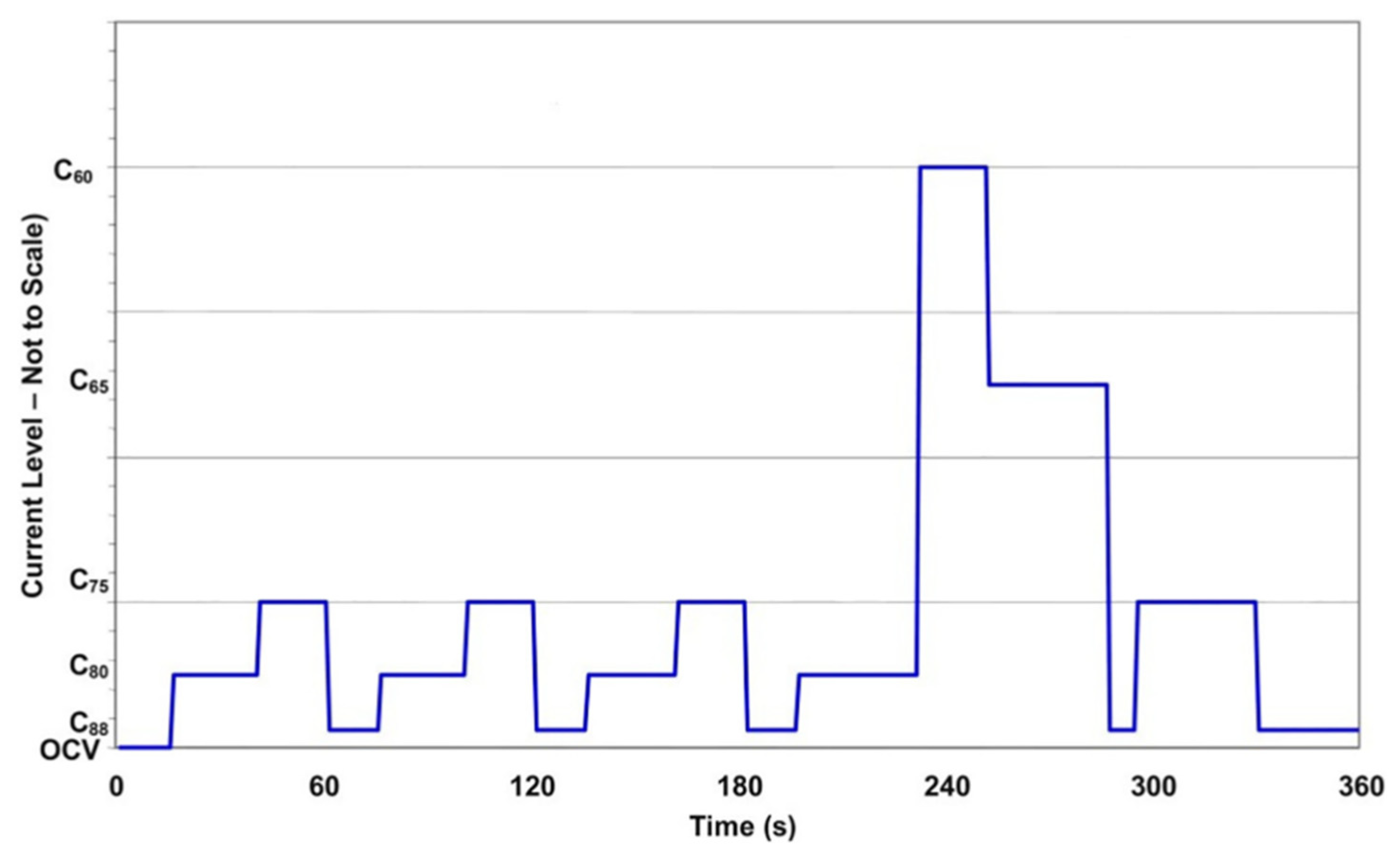
  141. Xu, L.; Reimer, U.; Li, J.; Huang, H.; Hu, Z.; Jiang, H.; Janßen, H.; Ouyang, M.; Lehnert, W. Design of durability test protocol for vehicular fuel cell systems operated in power-follow mode based on statistical results of on-road data. J. Power Sources 2018, 377, 59–69. [Google Scholar] [CrossRef]
  142. Rosini, S.; Micoud, F.; Araya, S.S.; Veltze, S.; Nygaard, F.; Hunger, J. Test Module D-01: Constant Load Durability; Zentrum für Sonnenenergie- und Wasserstoff-Forschung Baden-Württemberg (ZSW): Ulm, Germany, 2015. [Google Scholar]
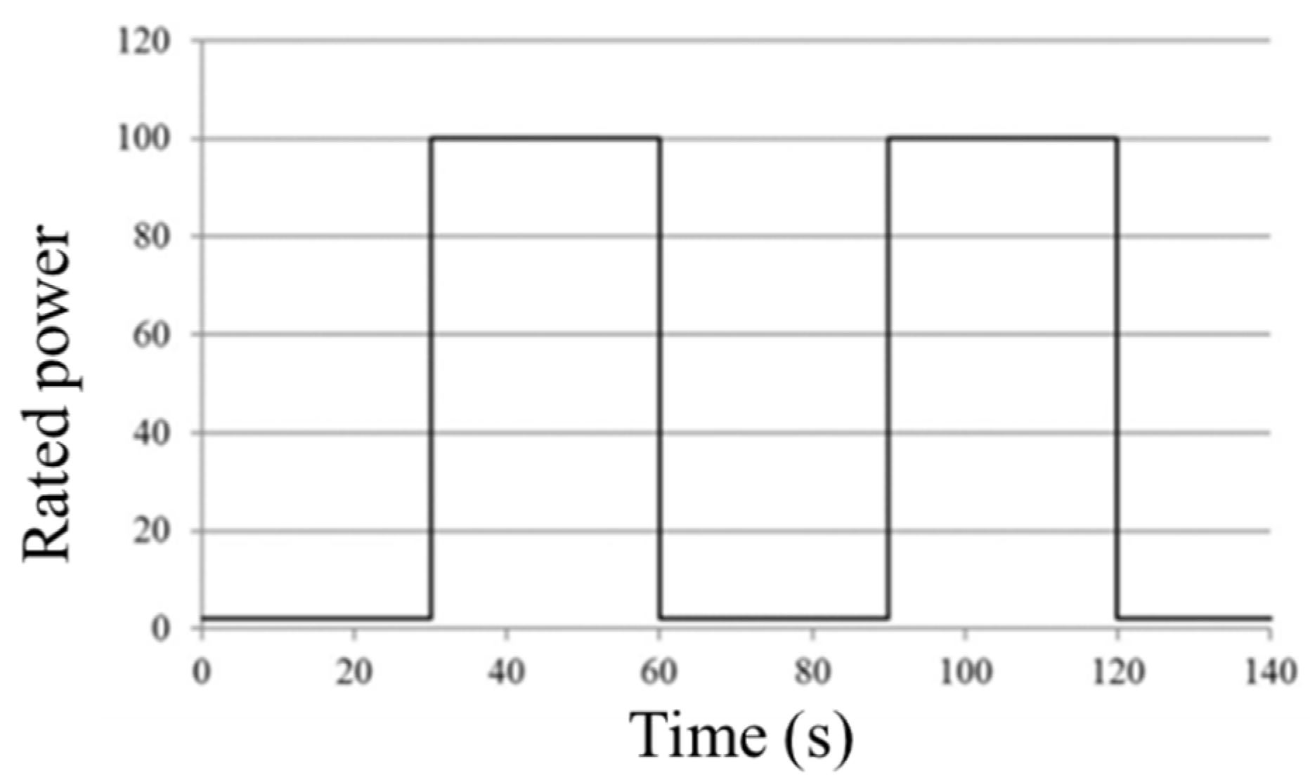
  143. Topal, L.; Harms, C.; Kabza, A.; Hunger, J. Test Module D-02: Load Cycling Durability; Zentrum für Sonnenenergie- und Wasserstoff-Forschung Baden-Württemberg (ZSW): Ulm, Germany, 2015. [Google Scholar]
  144. Harms, C.; Topal, L.; Veltzé, S.; Kabza, A.; Hunger, J.; Nygaard, F. Test Program D-01: Durability; Zentrum für Sonnenenergie- und Wasserstoff-Forschung Baden-Württemberg (ZSW): Ulm, Germany, 2015. [Google Scholar]
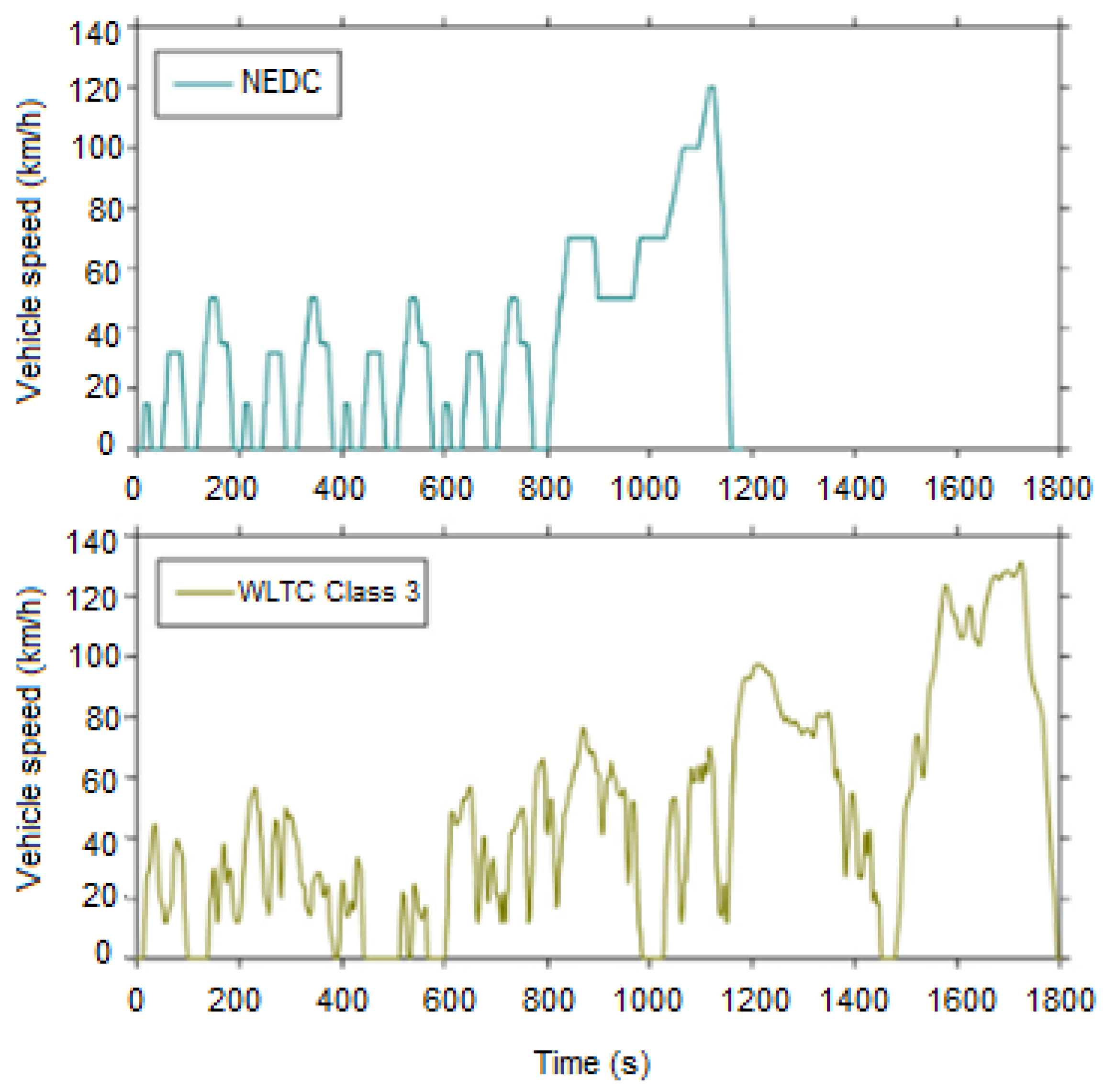
Figure 1. The Dynamic Stress Test (DST) duty cycle used for fuel cell testing [2] (Reprinted with permission from Borup et al. [2]. Copyright (2007) American Chemical Society).
Energies 14 04048 g001
Figure 2. The Fuel Cell Technical Team (FCTT) duty cycle [119] (Reproduced with permission from Ira Bloom et al. [119], Journal of Power Sources; published by Elsevier B.V, 2013).
Energies 14 04048 g002
Figure 3. Schedule of Fuel Cell Dynamic Load Cycle (FC-DLC) profile of the New European Driving Cycle (NEDC) [121] (Reproduced with permission from Jeasu Han et al. [121], International Journal of Hydrogen Energy; published by Elsevier Ltd., 2020).
Energies 14 04048 g003
Figure 4. NEDC and World Harmonized Light-Duty Vehicle Test Cycle (WLTC) class 3 driving profiles over time [129] (Reproduced with permission from D. Tsokolis et al. [129], Applied Energy; published by Elsevier Ltd., 2016).
Energies 14 04048 g004
Figure 5. The dynamic test profile proposed by FCTESTNET [133] (Reproduced with permission from Ira Bloom et al. [133], ESC Transactions; published by The Electrochemical Society, 2013).
Energies 14 04048 g005
Figure 6. Duty cycle from International Electrotechnical Commission (IEC) and Fuel Cell Testing and Standardization Network (FC TestNet) [120] (Reproduced with permission from Ira Bloom et al. [119], Journal of Power Sources; published by Elsevier B.V, 2013).
Energies 14 04048 g006
Figure 7. Evolution of speed versus time for the 10–15 protocol [4] (Reproduced with permission from Huicui et al. [4], Applied Energy; published by Elsevier Ltd., 2018).
Energies 14 04048 g007
Figure 8. Evolution of speed versus time for the 10–15 protocol [4] (Reproduced with permission from Huicui et al. [4], Applied Energy; published by Elsevier Ltd., 2018).
Energies 14 04048 g008
Figure 9. Tongji university test protocol [4] (Reproduced with permission from Huicui et al. [4], Applied Energy; published by Elsevier Ltd., 2018).
Energies 14 04048 g009
Figure 10. Tsinghua University test protocol [4] (Reproduced with permission from Huicui et al. [4], Applied Energy; published by Elsevier Ltd., 2018).
Energies 14 04048 g010
Figure 11. Wuhan University of Technology test protocol [4] (Reproduced with permission from Huicui et al. [4], Applied Energy; published by Elsevier Ltd., 2018).
Energies 14 04048 g011
Figure 12. Dalian Institute of Chemical Physics test protocol [4] (Reproduced with permission from Huicui et al. [4], Applied Energy; published by Elsevier Ltd., 2018).
Energies 14 04048 g012
Figure 13. An example of a PEMFC stack long-term durability experiment.
Energies 14 04048 g013
Figure 14. Variation of the stack load for the CHP load profile.
Energies 14 04048 g014
Table 1. The major failures of components in a polymer electrolyte membrane fuel cell (PEMFC) [19,84].
ComponentFailure ModesCauses
MembraneMechanical degradationMechanical stress due to non-uniform pressing and swelling Penetration of the catalyst and seal material traces and foreign particles
Chemical degradationRadical attack
Contaminations
Conductivity lossIonic contaminations
Catalyst/catalyst layer CLsActivation lossesSintering or de-alloying of electrocatalyst
Conductivity lossCorrosion of catalyst support
Loss of reformate toleranceDissolution of alloying elements and contamination
Decrease in mass transport rate of reactantsMechanical stress
Decrease in water management abilityChanging in hydrophobicity of materials
GDLDecrease in mass transportMechanical stress, compression
Degradation of backing material
Decrease in water management abilityMechanical stress
Change in hydrophobicity of materials
ThinningCorrosion
Bipolar plateConductivity lossCorrosion, oxidation
Fracture/deformationMechanical stress
Sealing gasketMechanical failure and brittlenessDeformation, compression, and chemical reaction
Table 2. Origin of common fuel and air impurities [2] (Reprinted with permission from Borup et al. [2]. Copyright (2007) American Chemical Society).
SourcesPotential Impurities
Hydrogen fuel impuritiesCrude oilCO, NH3, H2S, HCN, hydrocarbons
Natural gasCO, NH3, H2S, HCN, hydrocarbons
MethanolCO, odorants, alcohols
BiomassCations, aldehydes, alcohols, formic acid, NH3, H2S, HCN
Water electrolysisAnions, cations
Air impuritiesFuel combustion pollutionSOx, NOx, hydrocarbons, soot, and particulates
Ambient air, farmingNH3
Natural sourcesOcean salts, dust
OthersDeicersNaCl, CaCl2
Fuel cell corrosion productsCations, anions
Table 3. Current density vs. time for cycle profile (Reprinted with permission from Borup et al. [2]. Copyright (2007) American Chemical Society).
Step Duration (s)CxxStepDuration (s)Cxx
115OCV920C75
225C801015C88
320C751135C80
415C881220C60
524C801335C65
620C75148C88
715C881535C75
825C801640C88
Table 4. Main differences between NEDC and Worldwide Harmonized Light Vehicle Test Procedure (WLTP) [122,124,125,129,130,131].
Parameter NEDCWLTP (Class 3)Difference Note
Starting temperatureColdCold
Test cycleSingle test cycleDynamic cycle more representative of real driving
Cycle time1180 s1800 s+35%
Idle time23.7%13%−45%Less effect of engine start/stop
Cruise time38% 4% −90%Less stationary operation
Acceleration 20% 44% +117%More acceleration
Deceleration14% 40% +179%More deceleration
Cycle distance11 km23.25 km
Driving phasesTwo phases, 66% urban and 34% non-urban driving Four dynamic phases with more emphasis on high performance, 52% urban and 48% non-urban driving Two more
Average speed34 km/h46.5 km/h+53%
Maximum speed120 km/h131 km/h+4%
Table 5. Operating parameters of Giantleap.
ParametersUnitRef of NEDCGiantleap Conditions at Low Current DensityGiantleap Conditions at High Current Density
Nominal cell operating temperature°C807375
AnodeFuel gas inlet temperature°C857375
Fuel gas inlet humidity% RH50% (DPT 64 °C @ 80 °C)4545
Fuel gas inlet pressure (absolute)kPa250140190
Fuel stoichiometry 1.31.52.5
CathodeOxidation gas inlet temperature°C857375
Oxidation gas inlet humidity% RH30 (DPT 53 °C @ 80 °C)7575
Oxidation gas inlet pressure (absolute)kPa230130180
Air stoichiometry 1.51.71.7
Minimum current density for stoichiometry operationA/cm20.20.20.2
Table 6. Comparison of PEMFC durability test protocol of universities and institutes in China [4] (P—rated power, T—whole duration) (Reproduced with permission from Huicui et al. [4], Applied Energy; published by Elsevier Ltd., 2018).
Operating ConditionTongji UniversityTsinghua UniversityWuhan University of TechnologyDalian Institute of Chemical Physics
OCV7.3% of T 4.6% of T
Idling 38.9% of T 21.1% of T
Partial power80%P is 6.2% of T
70%P is 8.4% of T
90%P is 0.8% of T
20%P is 3.5% of T
40%P is 3.3% of T
60%P is 3.3% of T
80%P is 3.3% of T
40%P is 8.4% of T
60%P is 26.3% of T
80%P is 10.5% of T
Full power22.5% of T28.2% of T34.9% of T31.6% of T
Overload5.1% of T1.8% of T2.3% of T2.1% of T
Dynamic loadOCV to 15%P, cycling four times, 8.7% of T
OCV to 32%P, cycling four times, 17.4% of T
OCV to 50%P to 32%P, cycling four times, 23.6% of T
Idling to full power, cycling 20 times, 17.7% of TIdling to full power, cycling 40 times, 37.2% of T
Idling to overload, cycling five times, 4.7% of T
OCV to idling, cycling ten times, 9.3% of T
Table 7. Summary of applicable vehicle types of PEMFC durability test protocols.
ProtocolVehicle Types
Full Power CarsHybrid CarsCity Bus
Dynamic Stress Test (DST)
FCTT
NEDC
WLTP
FCTESTNET
Giantleap
JC08
Tongji University
Tsinghua University
Wuhan University of Technology
Dalian Institute of Chemical Physics
Table 8. Recommended nominal reference operating conditions for stationary application in STACKTEST project.
ParameterStationary Application
Combined Heat and Power (CHP)Backup
Stack temperature (Coolant inlet)70 °C65 °C
Reactant inlet temperature75 °C70 °C
Fuel stoichiometry1.21.25
Oxidation stoichiometry2.02.0
Fuel relative humidity80%40%
Dew point temperature fuel69.5 °C45.5 °C
Oxidant relative humidity80%40%
Dew point temperature oxidation65 °C45.5 °C
Fuel outlet pressureAmbient120 kPaabs
Oxidant outlet pressureAmbientAmbient
Publisher’s Note: MDPI stays neutral with regard to jurisdictional claims in published maps and institutional affiliations.