Article

Multivariable State-Feedback Controller Design for PV Inverter Connected to a Weak Grid

School of Electrical Engineering and Automation, Harbin Institute of Technology, Harbin 150001, China
*
Author to whom correspondence should be addressed.
Energies 2021, 14(15), 4441; https://doi.org/10.3390/en14154441
Submission received: 20 June 2021 / Revised: 14 July 2021 / Accepted: 15 July 2021 / Published: 23 July 2021

Abstract

:
This paper presents a robust multi-input multi-output (MIMO) state-feedback control scheme for a photovoltaic (PV) inverter connected to a weak grid. For a weak grid, the point of common coupling (PCC) voltage is very sensitive to the power disturbances and it is dynamically coupled to the PLL dynamics. So far, most of the control methods do not take into accounts these couplings. Therefore, in this paper, the MIMO controller was designed taking into account the dynamics of the phase-locked loop (PLL) and coupling effects between PCC voltage and the active power to enhance the system’s robustness. As result, the robust performance of the PV inverter interfaced to a weak grid was yielded. In addition, the sensitivity of the system to PLL was eliminated, allowing the use of larger PLL bandwidth even in a very weak grid. Based on the eigenvalues analysis method, a comparative study between the proposed control method and the conventional vector control method was performed. The proposed method is verified with simulations in PLECS and real-time simulations in the RT Box. The results show that the proposed MIMO control method preserves the system stability robustness against any change of grid strength, generated power and PLL bandwidth.

1. Introduction

Renewable energy sources such as photovoltaic systems, wind power, etc. are increasingly integrated into the grid through Voltage Source Converters (VSC) to overcome the climate change issues related to conventional energy sources for instance coal, fuels, etc. The large PV systems are located far away from the load centre and require a long transmission line to interface to the main grid [1]. With increasing PV system penetration, the grid strength, which is usually quantified by the SCR becomes increasingly weakened [2]. This is due to the increasing line impedance connecting the PV system to the grid, and the increased PV power generation that is constantly changing over time due to the weather conditions. As the grid becomes very weak with SCR < 3 [2], the VSC system stability becomes more challenging.
VSCs are controlled to generate harmonics free current regardless of the external disturbances which may be PV energy intermittence, uncertainties in physical component, etc. To achieve this, the vector control method in the synchronous reference frame (dq) is commonly used [3]. The vector control method consists of cascaded control loops with a faster inner-current control loop (CC) in dq frame, which is responsible for the grid current regulation and the slower response outer loops. The outer loops contain the DC-link voltage controller (DVC) to regulate the DC-link voltage by generating the d-axis current reference for CC and the AVC that regulates the PCC terminal voltage by producing the q-axis current reference to CC. In addition, the synchronous PLL (SRF-PLL) is used for the synchronisation of the VSC to the grid.
With a weak grid connection, the PCC voltage is sensitive to the active power and that leads to the coupling of the PCC voltage and PLL control dynamics as well as the DC-link control responsible for active power control.
References [4,5,6,7,8] analyse the dynamics and the coupling effects of the control loop and weak grid dynamics on VSC stability. From the analytical results in [6], the interaction of the PLL and DVC reduces the damping of low-frequency oscillations and therefore it may result in the lower-frequency instabilities, which are identified to range in frequency of the outer-loop control (AVC and DVC) and PLL [4,5]. Furthermore, such instabilities can be amplified by the AVC required to stabilise the VSC when it interacts with the weak grid by providing the required reactive power to compensate for the voltage drop across the line impedance. The same results were claimed in [4,5,9], where the coupling interaction between outer control loops (AVC and DVC), PLL and the weak grid induces low-frequency instabilities. Further studies were carried out in [10,11,12] to quantify the effects of control loops, PLL and the grid stiffness on the stability of the VSC.
The power transfer capability of the VSC is influenced by SCR and PLL bandwidth [7,8]. Both papers reported that the power transfer capability of the VSC is reduced due to weak grid connection (SCR < 3). Another important observation from [8] shows that the converter dynamics and power limit are affected, not only by the magnitude of this impedance but also by the Xg/Rg ratio. Furthermore, the larger PLL bandwidth also reduces the VSC capability. Therefore, for a weak grid operation, the PLL bandwidth must be reduced to increase the power transfer ability of the VSC as well as its dynamics performance. However, the smaller PLL bandwidth reduces the response time of the VSC.
Practically, the cascaded control loop and PLL parameters are systematically designed based on [13], where the inner loop bandwidth is selected to be 1/5 of the switching frequency, DVC bandwidth selected approximately 1/10 of the CC loop to limit their interaction. For a weak grid, the AVC loop is designed lower than the DVC to decouple their interactions and the PLL is designed to be slower than the AVC loop. Therefore, due to the above-mentioned couplings when VSC is connected to a weak grid, it is more challenging to independently design decoupled outer-loops and PLL to achieve the robust performances of the VSC.
To address the stability issues of VSC connected to a weak grid, many control methods have been proposed. In [9], the d-axis current reference is modulated by the PCC voltage to damp resonances oscillations occurring when the VSC interact with the weak grid and reference [14] proposed an alternative method to reduce the coupling between the active power and the PCC voltage by modulating the DC-link voltage or active power reference through d-axis current or PCC voltage.
In other efforts, references [15,16,17] proposed the robust controller design that enables stable operation of the inverter under a weak grid. The µ-synthesis CC cascaded with the H DC-link voltage controller for single-phase inverter are proposed in [15]. The proposed control methodology guarantees system robustness against weak grid uncertainties and achieve minimised DC bus voltage fluctuations, which are due to PV power fluctuations. Reference [16] proposed the optimal LQR method to optimally design the nested CC and DVC loops for the grid-connected converter and [17] proposed MIMO controller to overcome the effects of grid unbalance. In [15,16,17], however, the AVC loop, which is the necessity for a weak grid, was omitted and the dynamic effects of PLL were not considered during the design. Furthermore, [18] proposed an H robust control for the AVC loop to stabilise the system under a very weak grid while considering the PLL dynamics on PCC link voltage. The proposed controller decouples interactions between AVC and PLL dynamics, however, the coupling between the AVC and DVC remains an issue to be addressed.
In order to address the aforementioned control gaps, this paper proposed the optimal state-feedback MIMO controller design to enhance the robustness of a grid-connected PV inverter to a weak grid. To design the proposed controller, a reduced small-signal model of the inverter considering the dynamics effects of the PLL is derived. Furthermore, the feedback gains are optimally designed by minimising the quadratic cost function problem by the linear quadratic regulator (LQR) method. The robust controller designed is responsible for tracking the DC-link voltage and the PCC voltage with zero-steady state error, while ensuring the robust performance of the system against grid uncertainties and the PV system power intermittency. In addition, as the controller parameters are designed considering the PLL dynamics, the system robustness against PLL dynamics is enhanced. Furthermore, the system instabilities due to coupling effects of the control loops and grid dynamics are addressed as the proposed controller is designed taking into account all coupling issues.
The rest of the paper is organised as follows: In Section 2, the structure of the studied system is presented; in Section 3, the grid-connected PV inverter system is modeled; Section 4 presents the design methodology of the proposed controller; in Section 5, a comparative stability analysis and simulation results of the proposed control and the vector control is performed; finally, conclusions are drawn in Section 6.

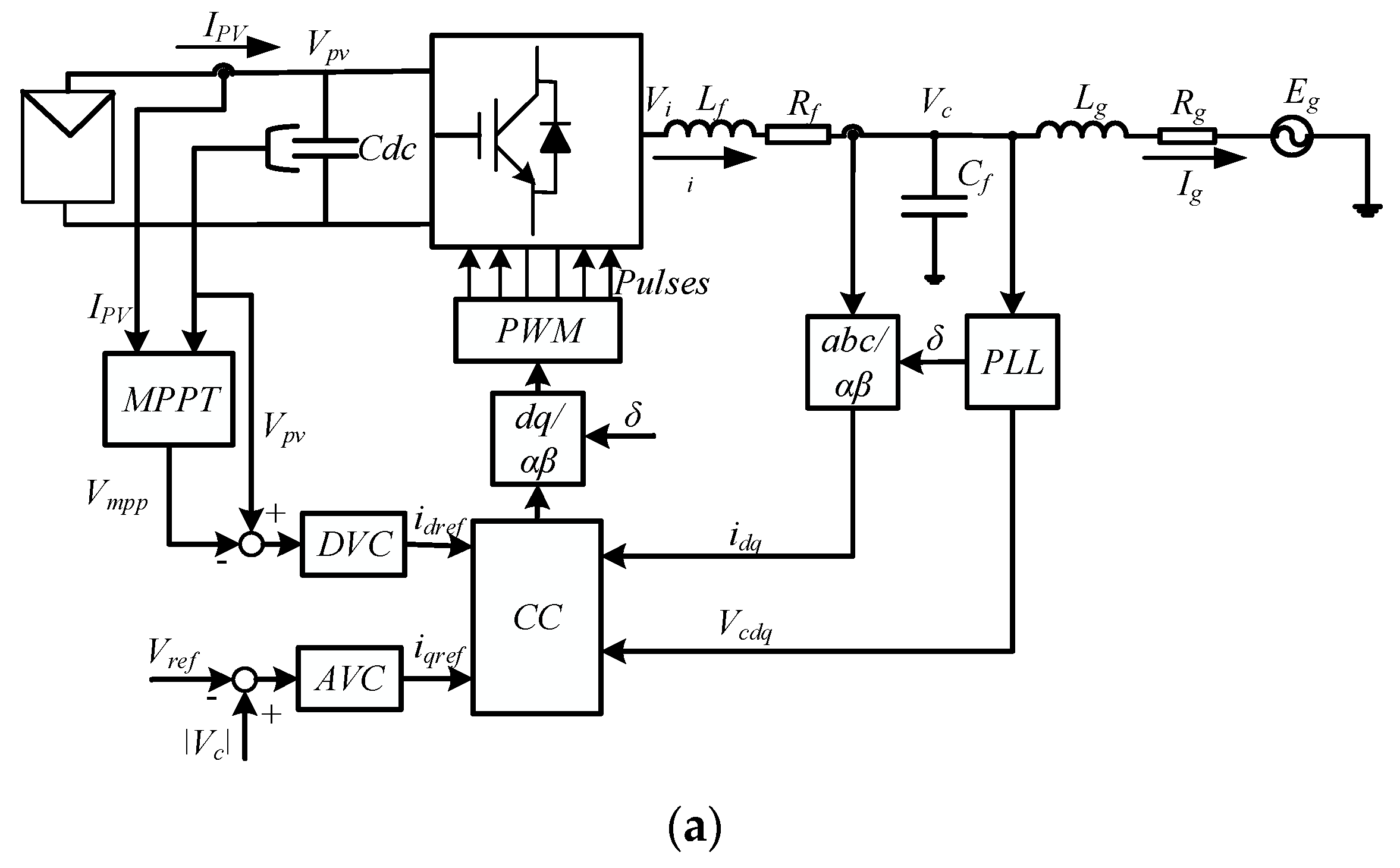
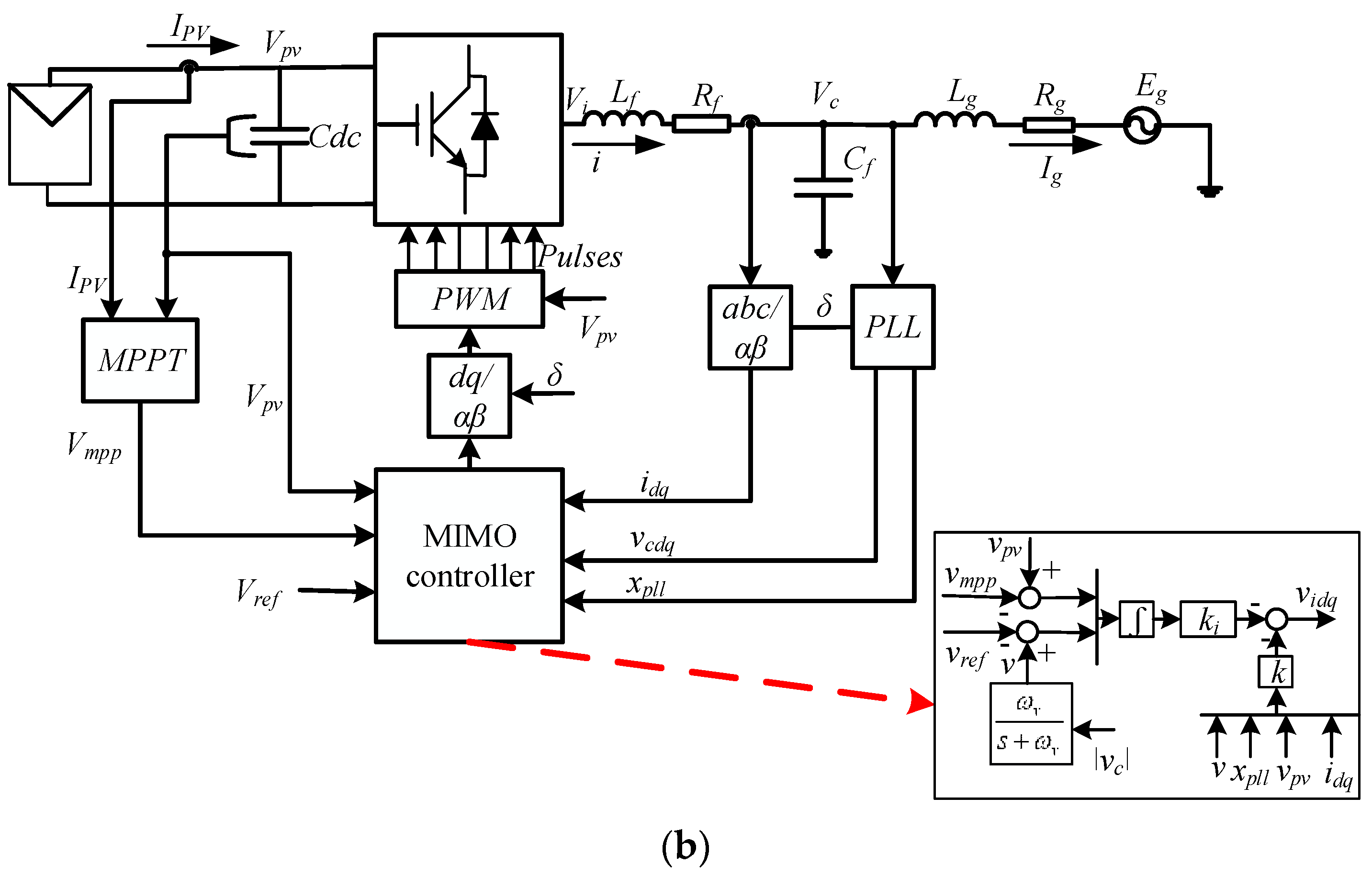
2. Structure of the Single-Stage Grid-Connected PV Inverter

Figure 1 shows the block diagram of a single-line representation of a single-stage three-phase grid-connected PV inverter with the control system, where Figure 1a shows the inverter with a conventional cascaded control loop and Figure 1b shows the proposed control. The system voltages such as Vi, Vc and Eg represent the input, ac capacitor and the grid voltage vector respectively. The PV source is linked to the VSC inverter through a DC-link capacitor (Cdc) responsible for power smoothing by maintaining the grid power and PV power balance. The power generated by the PV inverter depends on both DC-link terminal voltage (Vpv) and the PV current Ipv, which also depends on solar insolation (G). The two-stage converter equipped with IGBT switches is used to convert the DC power to AC power. The generated high harmonics due to the switching of the power switches are damped out via a high-pass filter composed by the filter inductor Lf with parasite resistance Rf and filter capacitor Cf. The rest of the system is linked to the main grid via a transmission line consisting of grid inductor Lg and grid resistance Rg. For the inverter control system as presented in Figure 1, the conventional control method in Figure 1a uses cascaded control loops with inner CC and the outer loops consisting of DVC and AVC loops whereas the proposed control is shown in Figure 1b. The MIMO control system firstly regulates the DC-link voltage to follow its reference obtained from maximum power point tracking (MPPT). Secondly, to provide voltage support by controlling the PCC voltage to track its reference. The feedback variables for the MIMO controller include the PLL states (xpll), the measured DC-link terminal, the measured filter inductor current and the measured capacitor voltage (PCC voltage) transformed into dq (vcdq) by PLL. A MIMO controller generates the modulating signals, which are applied to the PWM via dq/αβ to generate the switching pulses for the converter switches.

3. Grid-Connected PV Inverter Modelling

In order to design the proposed controller in this paper, a mathematical model describing the dynamics of VSC in Figure 1b is firstly derived. For simplicity, the filter capacitor is omitted as it presents a short-circuit link for high-frequency components and our goal here mainly is to damp the induced low-frequency oscillations. Therefore, the model includes the dynamics of the DC-link capacitor, filter and grid inductor dynamics and as well as the measurement PLL loop dynamics. By including the PLL dynamics in the design, the obtained MIMO control will be insensitive to the PLL bandwidth change; thus, a wider bandwidth PLL can be used even when the inverter is connected to a very weak grid while maintaining the system stability constraint.

3.1. Phase-Locked Loop (PLL)

In this paper, a conventional SRF-PLL in [19] depicted in Figure 2 is used to synchronise the inverter to the grid. The PLL consists of abc/dq transformation, a PIpll regulator and VCO (voltage controlled oscillator) represented by the integrator. The PIpll controller regulates PCC q-axis voltage (vcq) to zero while aligning the d-axis voltage to the PCC voltage (vcd) vector and outputs the grid rotation frequency deviation. After, the sum of the angular frequency deviation and the reference rated angular frequency is integrated to generate the synchronous angle responsible for abc to dq transformation.
The mathematical equations describing the PLL dynamics are expressed in (1).
{ d δ d t = ω r e f + k p ω v c q + k i ω γ p l l d γ p l l d t = v c q
where ωpll is the rotational frequency deviation, k and k are the phase-locked PI integral constant and proportional constant of PIpll, respectively, γpll is the PLL integral state, ωref is the reference angular frequency and δ is the synchronous rotational angle.

3.2. DC-Link Dynamics

According to conservation law, the DC-link stability is maintained if and only if the power imbalance between the PV power and the input power to the VSC is zero [20]. Therefore, the DC-link voltage changes due to that power mismatch. The nonlinear dynamics equation describing that relationship is expressed as in Equation (2) [21,22].
C d c v p v d v p v d t = P p v 1.5 ( v i d i d + v i q i q )
where Ppv and Pin are the PV power and input power to the inverter respectively, id and iq are the dq current flowing into the grid, vid and viq are the converter output voltage in the synchronous frame.
The power generated by the PV generator depends on the terminal voltage and PV current, which also correspondingly depends on weather conditions. The mathematical equation describing the PV generator power-voltage dynamic is found in [23] and is written in Equation (3).
P p v ( G , T , V p v ) = v p v I p v = n p I p h v p v n p I r s v p v ( e ( v p v q / n s K A T ) 1 )
where q = (1.602 × 10⁻¹⁹ C) is the electron charge, K = (1.38 × 10⁻²³) is Boltzmann constant, T is the module temperature, Iph is the photon current, Irs is the saturation current and A is the ideality factor, while ns and np represent the number of the interconnected PV module in series and parallel, respectively.

3.3. Filter Inductor and Grid Inductor Dynamics

From Figure 1b, as the filter capacitor was omitted, the current through the filter inductor i is the same as the grid current ig. Since the controller is implemented in converter dq frame defined by the PLL, thus the inductor dynamics is modelled in the converter frame. To obtain the inductor nonlinear dynamics in the synchronous reference frame, the grid voltage is first transformed into the converter’s dq reference frame in Equation (4), and Equation (5) is yielded.
E g = E e j δ
L t d i d d t = v i d R t i d + ω g L t i q E cos ( δ ) L t d i q d t = v i q R t i q ω g L t i d + E sin ( δ )
In Equations (4) and (5), Lt = Lf + Lg and Rt = Rf + Rg are the total system inductance and total parasite resistance, id and iq are the dq current flowing into the grid, vid and viq are the converter output voltage in the synchronous frame, E is the grid voltage magnitude and ωg is the grid frequency, which is considered to be constant.

3.4. PCC Voltage Dynamics

To enhance the stable operation of a VSC-inverter connected to a weak grid, a PCC voltage controller is required. As the Cf dynamics were omitted, to access the PCC voltage state, the measured PCC voltage is feedback via a low pass filter with cut-off frequency ωv. The state corresponding to the feedback low-pass filter is obtained in (6)
d v d t = ω v v + ω v | v c |
In Equation (6), vc denotes the PCC voltage vector and is expressed as v c = v c d 2 + v c q 2 and v is the voltage output of the PCC voltage measurement filter.
The PCC voltage in the synchronous frame can be expressed as a function of the grid impedance and the synchronous angle. That will reflect the grid dynamics and can be expressed in Equation (7)
v c d = R g i d x g i q + E cos ( δ ) v c q = R g i q + x g i d E sin ( δ )
For linear controller design, the dynamic Equations (1)–(7) describing the system behaviour need to be linearised to eliminate the non-linearities in the system model. Therefore, the Equations (1)–(7) are linearised following the method in [24], around steady-state operating points, which are obtained through time-domain simulation of the model in Figure 1 using the system parameters in Table 1. The state-space representation of the obtained linear system model is yielded in Equation (8).
d x d t = A x + B u y = C x
where x is the state vector and is given as x = [id iq vpv δ γ v]T, u is the control vector that is expressed as u = x = [vid viq]T and y is the output vector denoted as y = [vpv v]T. State-space matrices A, B and C are shown below.
A = [ R t L t ω g 0 E q 0 L t 0 0 ω g R t L t 0 E d 0 L t 0 0 1.5 v i d 0 a 1.5 v i q 0 a ( i p v + G m ) a 0 0 0 K p ω x g K p ω R g 0 K p ω E d 0 K i ω 0 x g R g 0 E d 0 0 0 ω v R g ω v x g ω v E q 0 0 0 ω v ] B = [ 1 L t 0 0 1 L t 1.5 i d 0 a 1.5 i q 0 a 0 0 0 0 0 0 ] C = [ 0 0 1 0 0 0 0 0 0 0 0 1 ] ,
with Eq0 = Esin(δ0), Ed0 = Esin(δ0), a = vpv0 × Cdc, Gm = −(npqirs/nsKTA)e(qvpv/nsKTA) is the internal conductance of the PV generator obtained from Equation (3) and the subscript 0 represent a steady-state value corresponding to that variable. From the state-space model of the system presented above, the MIMO controller can be designed. It is straightforward to design the MIMO state-feedback controller as the system in (8) is fully controllable and all states variables are accessible to the control method without additional measurements devices compared to the conventional cascaded control method. The LQR is the best candidate to optimally design the state-feedback controller.

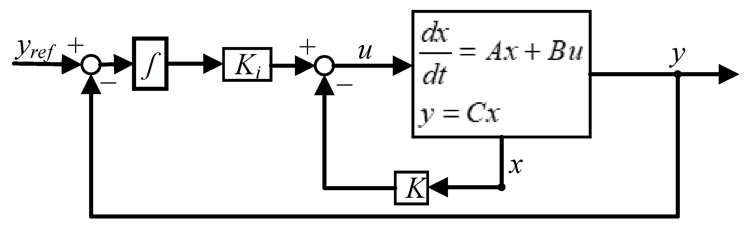
4. Proposed MIMO Controller Design

In modern control engineering theory, the linear-quadratic optimal control (LQR) plays a crucial role due to its simplicity and robustness to external disturbances while maintaining the asymptotic stability of the system [25,26]. As the system [A,B] stabilisability and [A,C] detectability holds, the control input signal from the system (8), is calculated based on control law expression (9) as in [25,26]
u = k x
where the optimal state-feedback gain K = R−1BTP is obtained by minimising the quadratic cost-function expressed in (10).
J ( u ) = 0 ( x T Q x + u T R u ) d t
Q and R represent the positive semi-definite and positive definite weighing matrices, respectively. P is the unique, symmetric, positive semi-definite solution of the algebraic Riccati equation (ARE) (see Equation (11)).
A T P + P A + Q P B R 1 B T P = 0
Since the matrices Q and R are the only parameters to be designed, the closed-loop dynamics performance and the robustness are ensured with the optimal selections of the Q and R matrices. The matrices Q and R can be optimally selected based on the method proposed in [27,28], where Q and R matrices are iteratively varied and from either closed-loop eigenvalues or closed-loop systems response, the impact of Q and R can be observed.
As the aim of the proposed control system is to ensure zero steady-state error for DC-link voltage and PCC voltage while maintaining the robustness of the grid-connected PV inverter to a weak grid; thus, an integral control action must be included in the controller. Basing on Figure 3, the new system state-space equations are yielded in (12):
d x d t = A x + B u y = C x d ζ d t = y r e f y = y r e f C x
where ζ is the state of the integrator and is given as ζ = [ζ1 ζ2]T. ζ1 is the DC-link voltage error expressed as ζ1 = vmppvpv error while ζ2 is the PCC voltage error expressed as ζ1 = vcrefv. Therefore, in-state representation form, the overall system dynamics in (12) can be written as:
d d t [ x ζ ] = [ A 0 C 0 ] [ x ζ ] + [ B 0 ] u + [ 0 1 ] y r e f y = [ C 0 ] [ x ζ ] T
Furthermore, the overall input signal is obtained from Equation (9) by including the states of the integrator yielding (14).
u = k x k i ζ = k t [ x ζ ] T
Ki represents the state-feedback gain of the integrator states and kt = [ki k]. Here a matrix kt of 2 × 8 is obtained, with k is 2 × 6 and ki is 2 × 2.
After selecting the optimal matrices Q and R based on [27], the feedback gain Kt is deduced using Matlab function lqr. The optimal values of Q = diag(10, 10, 500, 1, 1, 0.1, 10 × 10−6, 10 × 10−4) and R = diad(1,1) are obtained with system parameters in Table 1.
For further analysis of the impact on the stability of the system parameters with the proposed control method, a state-space representation of the closed-loop system is deduced from (13) and (14) yields in (15).
d d t x c = A c x c + B c y r e f
A c = [ A 0 C 0 ] + [ B 0 ] K t and B c = [ 0 e y e ( 2 ) ]

5. Comparative Stability Analysis and Simulation Results

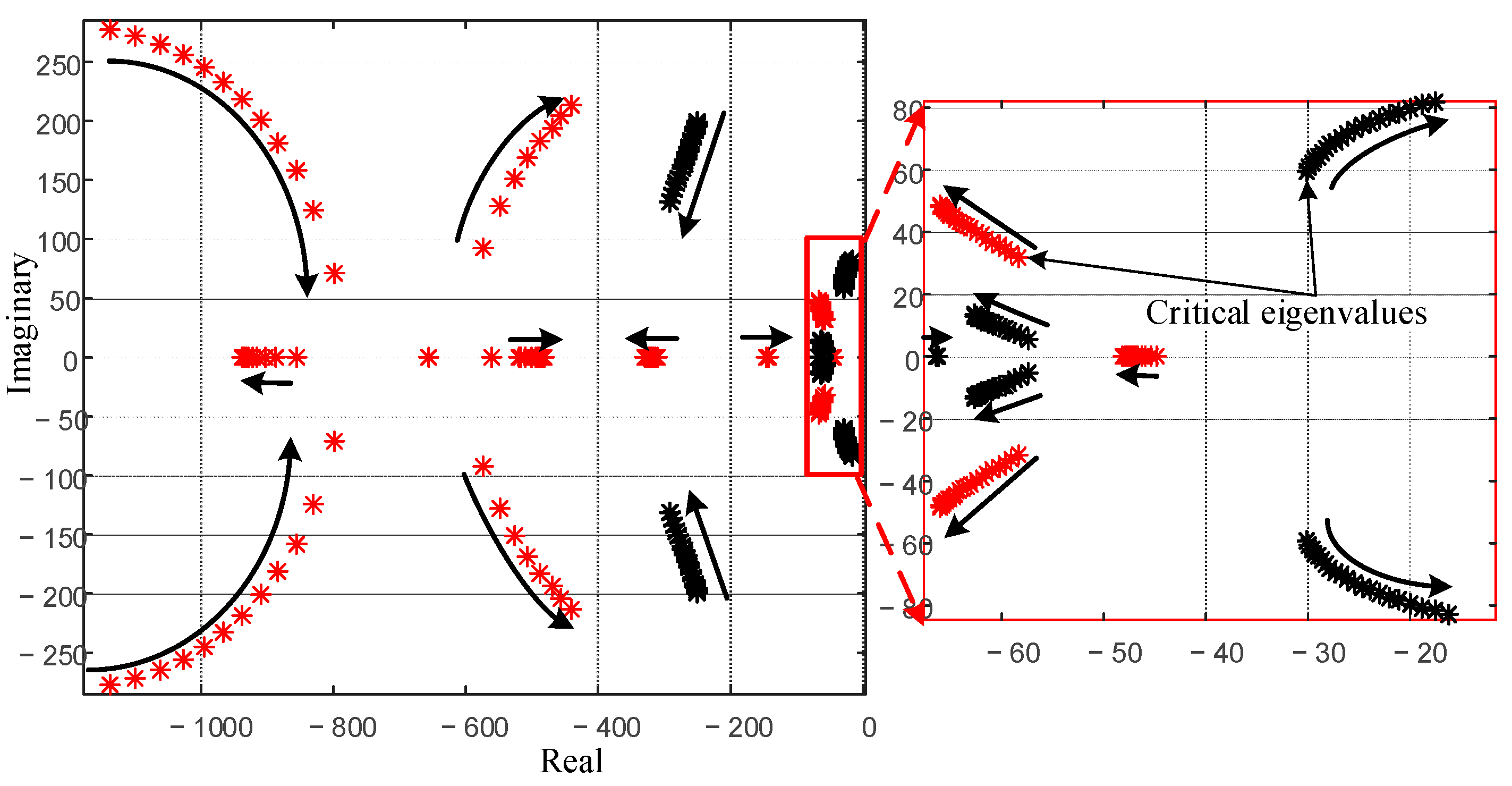
5.1. Stability Analysis

With the proposed MIMO control, the inner current loop and the outer DC-link controller and AVC loop are lumped as a single controller designed to optimally stabilise the system regardless of the system parameters uncertainties and PV power disturbances. The states feedback gain Kt was optimally designed to enhance the robust performance. Since the designed controller takes into account the dynamics of PLL, the obtained controller is robust to the PLL dynamics. Therefore, the response of the PLL will have little impact on the system performance. To compare the proposed control method with the conventional cascaded vector control method, the outer loops and the inner CC was designed based on [29]. The optimal bandwidth of the outer-loops was selected based on the small-signal model developed in [1], where 20 Hz and 50 Hz of AVC and DVC, respectively, are obtained and 1/5 of switching frequency for CC is used. The PLL bandwidth is selected to be 10 Hz.
The parameters that affect the system stability apart from the control loop, consist of PLL, the power level, and the grid strength (it is quantified by the SCR). The comparative stability of the proposed MIMO control method is analysed based on the eigenvalues method. The closed-loop system eigenvalues of the proposed control are obtained from (13), while the model for cascaded control, the closed-loop eigenvalues are obtained based on the model derived in [1]. The system eigenvalues are plotted in root-locus, where the red colour indicates the eigenvalues of the MIMO system while the black colour indicates the eigenvalues for the vector control method. In addition, the direction of the eigenvalues movement is indicated by the arrows when the corresponding variable increases.

5.1.1. Impact of the Power Level

Figure 4 shows the sensitivity of the system eigenvalues corresponding to the increase in the solar insolation from 500 W/m2 to 1200 W/m2. For the increase in the solar insolation (i.e., The increase in the generated PV power), the characteristic eigenvalues of the system change as indicated in Figure 4. For low power levels, corresponding to the low solar insolation, the most critical eigenvalues are far from the imaginary axis with large negative real value. Thus, the system is highly damped and hence the PV inverter stability is guaranteed. However, when the solar insolation increases, the critical eigenvalues become poorly damped as they move towards the right-half plane for the vector control method. They may become unstable if their real parts become positive. Compared to vector control, the proposed MIMO system yield higher damping as all system eigenvalues remains far from the imaginary axis, with a large damping ratio. The other eigenvalues move as indicated in Figure 4 and yield high damping with the MIMO control method.

5.1.2. Impact of the Grid Inductance

By comparison of the vector control and the MIMO proposed control system, the eigenvalues of the proposed method are located in a more damped location far from the imaginary when the grid inductance changes from 2.5 mH (SCR = 2.02) to 5.5 mH (SCR = 0.95) (see Figure 5). It is clear that for the proposed MIMO control, the system dynamic stability is maintained for a very weak grid as the critical eigenvalues do not move towards the right-half plane. On the other hand, for the cascaded vector method, the system stability is worsened as critical eigenvalues move toward the right-half plane with a reduction in damping ratio when the grid inductance increases (see Figure 5). The critical eigenvalue can move into the unstable region (become positive eigenvalues) if the system grid inductance continues to increase. Therefore, the stability of the system becomes challenging when the grid becomes weak for vector control.

5.1.3. Impact of PLL

Another parameter affecting the system stability is the PLL, which is used to capture the grid synchronisation angle. Under the operation of the weak grid, the PLL dynamics are dynamically coupled to the PCC voltage, and this coupling may exacerbate the system stability. For the vector control method, when the PLL bandwidth (PLL_BW) increases, the critical eigenvalues move to the right-half plane and become positive eigenvalues for a large value of the PLL bandwidth as can be observed in Figure 6. Therefore, for a weak grid connection, a low bandwidth PLL is required to maintain the system stability. On the other hand, when the PV inverter is under control of the proposed MIMO system, the system stability is maintained when the PLL bandwidth increases as critical eigenvalues do not sweep towards the right-half plane. All eigenvalues remain in the left-half plane for a whole range of variation of the PLL bandwidth. This gives freedom in selecting the PLL bandwidth.

5.2. Simulations and Experimental Results of the Case Study

In order to verify the correctness of the proposed MIMO control system over the conventional vector control method, the simulations are carried out in PLECS simulation software while the experimental results are obtained through real-time simulation in the RT Box. The simulation results are presented to quantify the system robustness over external disturbances (grid inductance uncertainties and PV power disturbance) and PLL dynamics. The stability analysis in the previous section shows that for the conventional control method, the low-frequency resonance oscillations may be induced when the critical eigenvalues are poorly damped (system unable to withstand the oscillations caused by disturbances). The low damping ratios of the critical eigenvalues are due to the increase in PLL bandwidth, increase in solar insolation and reduction of SCR (corresponding to an increase in grid inductance). On the other hand, for the proposed control method as presented above, the dominant eigenvalues of the system are highly damped, resulting in a stable system even when the system is subjected to disturbances. The system parameters used in simulations are presented in Table 1.

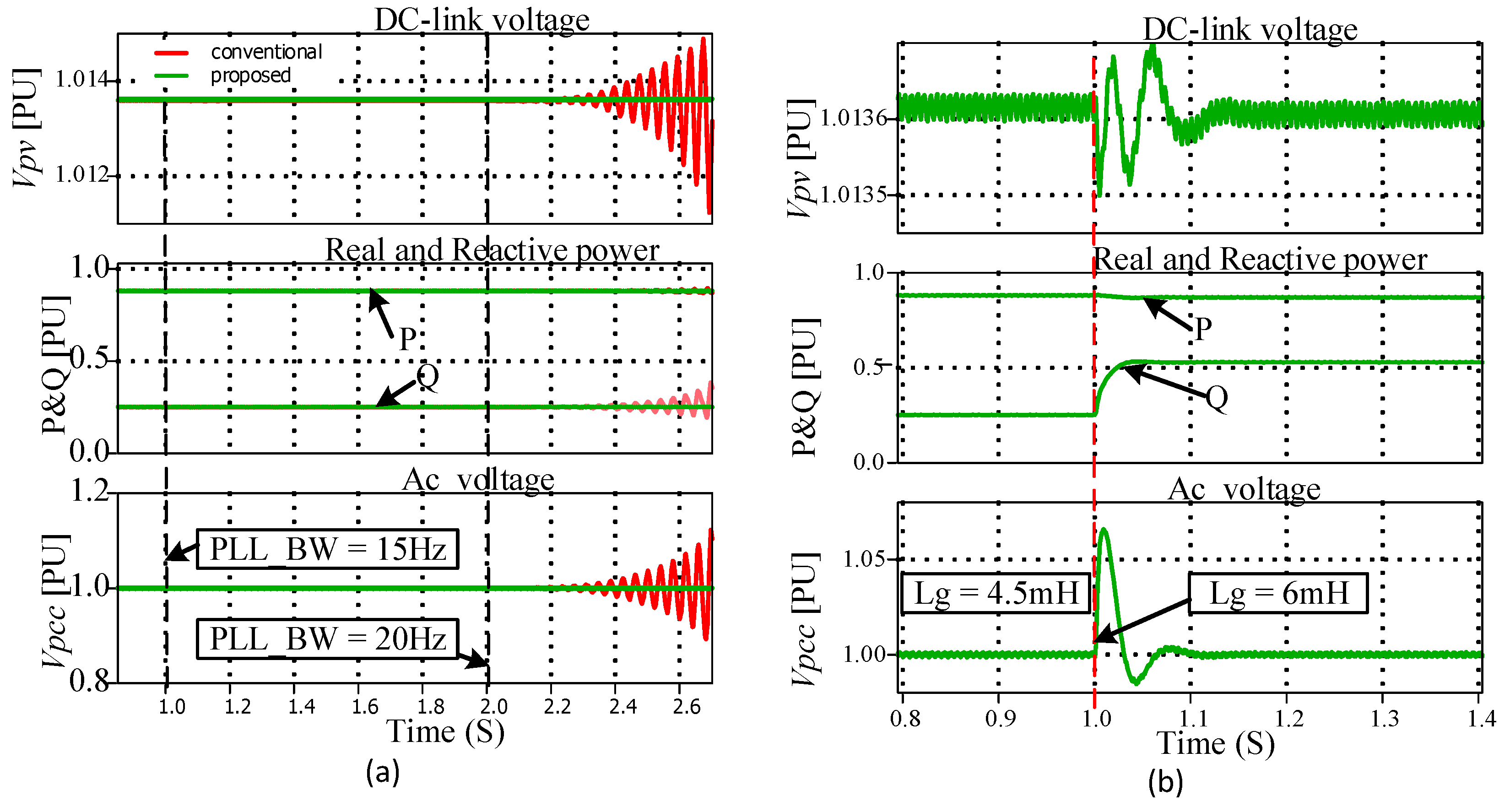
5.2.1. Simulations Results

Figure 7a shows the response of the system for a step change of solar insolation from 800 W/m2 to 950 W/m2 at 1 s and then to 1085 W/m2. For both control systems, the system operates stably at low values of Gm = 800 W/m2 where the active power is 0.72 PU, reactive power is 0.146 PU and the Vmpp = 1 PU as can be shown in Figure 7a. The DC-link voltage follows the reference Vmpp obtained from the MPPT and the PCC voltage follows its reference values. When a step change of solar insolation occurs at 1 s, with G jumps to 950 W/m2 corresponding to steady-state of 0.85 PU and 0.235 PU active and reactive power, respectively, and 1.01 PU maximum PV voltage, the rapidly dying oscillations occur for conventional control method, while for the proposed MIMO system there are no induced oscillations. Moreover, the amplitude overshoot for the MIMO system is very low compared to vector control. When the system steady-state is reached, both control systems operate stably.
When solar insolation jumps from 950 W/m2 to 1085 W/m2 undamped oscillations resonating at 15 Hz are induced for the vector control method as can be observed in Figure 7a. These oscillations are due to the low damping ratio of the system as the critical system eigenvalues are closer to the imaginary axis for a large value of solar insolation. For MIMO control, the inverter continues to operate stably without any undamped oscillations as predict. Even for the large value of the solar insolation, as indicated in Figure 8a when solar insolation changes from 1000 W/m2 to 1150 W/m2, the system stability holds. This confirms the higher robustness capability of the proposed system even when large disturbances in solar insolation occurs when the PV inverter is connected to a weak grid. Therefore, the system’s robust performance is guaranteed.
From Figure 9, we can also observe that the system response and performance are guaranteed when the solar insolation jumps to a lower value. The output active power, DC-link voltage changes respectively with the changing of solar insolation, at first from 500 W/m2 to 1000 W/m2 and then from 1000 W/m2 to 250 W/m2. The PCC voltage continues to follow its reference with no undamped oscillations during the step change of solar insolation.
Figure 7b shows the response of the system when the grid inductance changes from 3.5 mH (corresponding to SCR = 1.44) to 4.15 mH (SCR = 1.22) at 1 s and then to 4.9 mH (SCR = 1.03) at 2 s. The output reactive power changes as the grid inductor change to compensate for the voltage drop across line impedance to maintain the PCC voltage at its reference value. For inverter under the proposed MIMO control system, the system stability is maintained without oscillations during step change of grid inductor as can be observed in Figure 7b. Likewise, the system robustness under the change in grid inductor is ensured even, when the inverter is interacting with the ultra-weak grid as shown in Figure 10b, where the grid inductance changes from 4.5 to 6 mH (SCR = 0.9). However, due to that change, the damped oscillations are induced in DC-link voltage, but the system stability is retained after reaching the steady state. Additionally, a large overshoot appears in PCC voltage.
On the other hand, when the vector control system is used, the resonance oscillations are induced as indicated in Figure 7b. When the grid inductor jumps from 3.5 to 4.15 mH, the oscillations in output power (Real power and reactive power) and voltage (DC-link and PCC voltage) resulted from that change are damped quickly. Furthermore, when grid inductance jumps from 4.15 to 4.9 mH, the underdamped oscillations resonating at 16 Hz are triggered in output power and voltage. For further increase in grid inductance, the system will become unstable. This confirms the analysis carried in the previous section, where we indicated that under vector control, the system starts losing its damping capability when the grid inductor increases.
Another parameter affecting the system stability is the PLL bandwidth. It was shown that with the vector control method, the system stability is affected by the variation of the PLL while the system becomes insensitive to PLL parameters when the proposed MIMO control system is used.
Figure 10a shows the system response for different values of PLL bandwidth. For the vector control method, it can be observed that for a low PLL bandwidth, the system presents a highly damped response as expected according to the previous system eigenvalues analysis. For a wider PLL bandwidth, the system stability is worsened and it may become unstable for a high value of PLL bandwidth. The system stability is maintained if the critical eigenvalues of the system have enough damping ratio to curtail the induced oscillations due to the PLL bandwidth change. As shown in Figure 10a, the system loses its stability when the PLL bandwidth jumps from 15 to 20 Hz, where undamped growing oscillations are triggered. However, when the vector control is changed to the proposed MIMO control method, the system becomes insensitive to the PLL bandwidth as can be observed in Figure 10a, where the system remains stable when PLL bandwidth changes from 10 Hz to 15 Hz and then to 20 Hz. The same results are claimed in Figure 8b with PLL bandwidth changes 10 Hz to 50 Hz and then jumps to 80 Hz. Even for a weak grid operation, the proposed control method gives a free choice on the PLL bandwidth while maintaining the system stability.

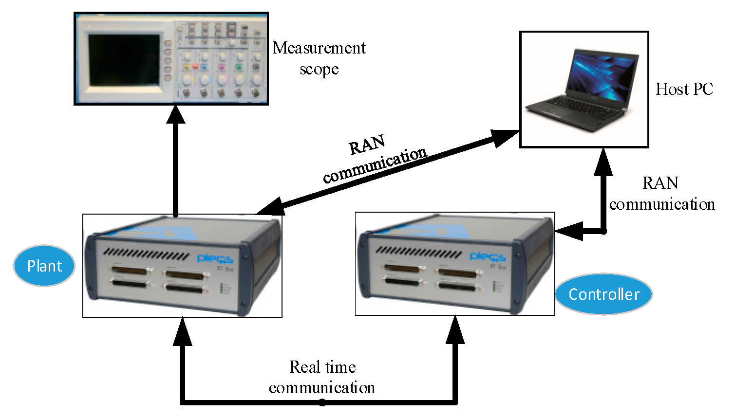
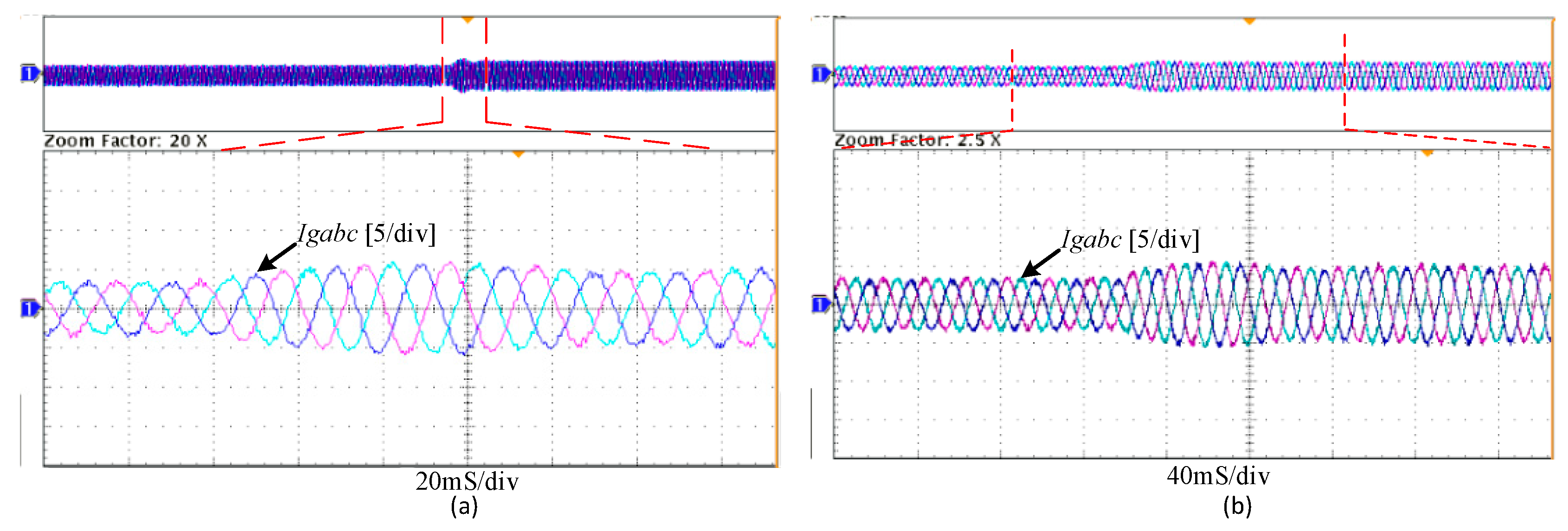
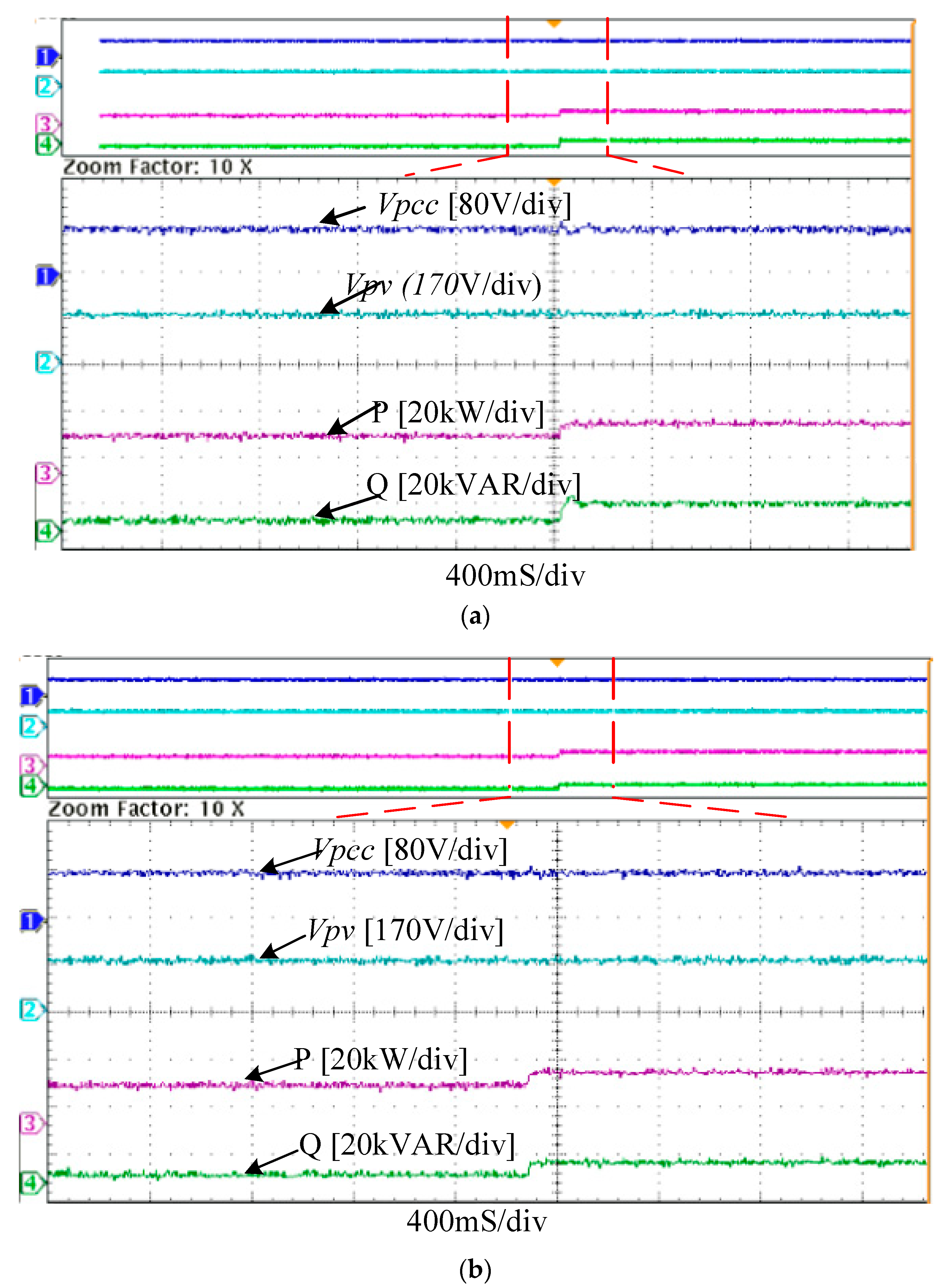
5.2.2. Experimental Results

To validate the simulation and the analysis presented in the previous sections, the proposed control method is implemented through real-time simulation performed in the PLECS RT Box presented in Figure 11. The real-time simulation platform is composed of Two RT boxes connected via theirs I/O digital and analog ports. One RT Box implements the control system and the second RT Box emulates the power part (plant). The measurement scope is connected to the RT Box that emulates the plant via the analog output port the host computer communicates with the system through a LAN communication link the detailed description and the operation of the setup can be found on the official website of the Plexim (plexim.com (accessed on 11 July 2021)).
The parameters in the real-time simulation are the same as in offline, which are defined in Table 1. The different scenarios are tested in order to verify the correctness of the proposed control method.
Figure 12a,b shows the grid current when the grid inductor is 5 and 4.5 mH, respectively. The gain of the current meter is set to 1/50. It can be observed from Figure 12 that a clean current is injected into the grid in both cases, when the grid inductor is 5 mH and when the grid inductor is 4.5 mH. When the system is subjected to a step-change in solar insolation from 850 to 1150 W/m2, the stability of the system is preserved and a clean current continues to flow into the grid even for a higher value of the grid inductor. However, a small overshoot is seen for a step change of solar insolation changes from 850 to 1150 W/m2 when the inverter is connected to the grid through 5 mH line inductance (see Figure 12a).
The same performance can be observed in Figure 13a,b representing the output power (reactive and active) and the output voltage (DC-link and Vpcc) for grid inductor equal to 4.5 mH and 5 mH, respectively. Due to higher damping of the proposed controller, no oscillations and overshoot resulted in a step-change of solar insolation from 850 to 1150 W/m2 for grid inductance equal to 4.5 mH as seen in Figure 13a. Nonetheless, if the grid inductance is 5 mH and the solar insolation is subjected to a step change from 850 to 1150 W/m2, no oscillations resulted but a little overshoot in output power and voltage occurs. The PCC voltage is maintained at the reference value for different PV power-level by injecting the corresponding reactive power to compensate for the line voltage drop. Thanks to the higher damping capability of the proposed system, the weak grid-connected inverter can effectively continue to transfer even when the PV power disturbances occur.

6. Conclusions

A MIMO state-feedback control method was proposed to enhance the stability of the grid-connected PV inverter to weak. Unlike the conventional vector control method where the coupling between PCC voltage, PLL and active power makes it difficult to independently control reactive power through AVC, and active power through DVC, the proposed MIMO control overcomes these coupling limitation issues. The proposed control system takes into account the dynamics of PLL and coupling between active power and the PCC voltage to enhance the robust performance of the PV inverter connected to a weak grid. The eigenvalues analysis method is used to evaluate the robustness of the proposed method against the conventional vector control method. Through small-signal stability analysis, it is revealed that the proposed control method achieves a high damped system, which is robust to the change of grid strength, solar insolation and the bandwidth of the measurement PLL. Based on time-domain simulations and real-time simulations in PLECS and RT Box respectively, the results were shown to validate the robustness and effectiveness of the proposed control method. Thanks to the proposed control method, the robust performance of the weak grid-connected PV inverter against disturbances is enhanced.

Author Contributions

Conceptualization, M.A.; methodology, M.A. and H.L.; software, M.A. and YY.; validation, M.A., Y.Y. and X.Z.; formal analysis, M.A. and H.L.; investigation, M.A.; resources, X.Z.; writing—original draft preparation, M.A.; writing—review and editing, M.A.,X.Z., and YY; visualization, M.A. and Y.Y.; supervision, H.L. All authors have read and agreed to the published version of the manuscript.

Funding

No external funding.

Institutional Review Board Statement

Not applicable.

Informed Consent Statement

Not applicable.

Conflicts of Interest

The authors declare no conflict of interest.

References

  1. Jia, Q.; Yan, G.; Cai, Y.; Li, Y.; Zhang, J. Small-signal stability analysis of photovoltaic generation connected to weak AC grid. J. Mod. Power Syst. Clean Energy 2019, 7, 254–267. [Google Scholar] [CrossRef] [Green Version]
  2. IEEE Guide for Planning DC Links Terminating at AC Locations Having Low Short-Circuit Capacities. In IEEE Standards 1204-1997; IEEE: Piscataway, NJ, USA, 1997; pp. 1–216.
  3. Yazdani, A. Voltage-Sourced Converters in Power Systems. Modeling, Control, and Applications; John Wiley & Sons, Inc.: Hoboken, NJ, USA, 2010. [Google Scholar]
  4. Huang, Y.; Yuan, X.; Hu, J.; Zhou, P. Modeling of VSC Connected to Weak Grid for Stability Analysis of DC-Link Voltage Control. IEEE J. Emerg. Sel. Top. Power Electron. 2015, 3, 1193–1204. [Google Scholar] [CrossRef]
  5. Huang, Y.; Yuan, X.; Hu, J.; Zhou, P.; Wang, D. DC-Bus Voltage Control Stability Affected by AC-Bus Voltage Control in VSCs Connected to Weak AC Grids. IEEE J. Emerg. Sel. Top. Power Electron. 2016, 4, 445–458. [Google Scholar] [CrossRef]
  6. Wang, D.; Liang, L.; Shi, L.; Hu, J.; Hou, Y. Analysis of Modal Resonance Between PLL and DC-Link Voltage Control in Weak-Grid Tied VSCs. IEEE Trans. Power Syst. 2018, 34, 1127–1138. [Google Scholar] [CrossRef]
  7. Zhou, J.Z.; Ding, H.; Fan, S.; Zhang, Y.; Gole, A.M. Impact of Short-Circuit Ratio and Phase-Locked-Loop Parameters on the Small-Signal Behavior of a VSC-HVDC Converter. IEEE Trans. Power Deliv. 2014, 29, 2287–2296. [Google Scholar] [CrossRef]
  8. Zhou, J.Z.; Gole, A.M. VSC transmission limitations imposed by AC system strength and AC impedance characteristics. In Proceedings of the 10th IET International Conference on AC and DC Power Transmission (ACDC 2012), Birmingham, UK, 4–5 December 2012; pp. 1–6. [Google Scholar]
  9. Rezaee, S.; Radwan, A.; Moallem, M.; Wang, J. Voltage Source Converters Connected to Very Weak Grids: Accurate Dynamic Modeling, Small-Signal Analysis, and Stability Improvement. IEEE Access 2020, 8, 201120–201133. [Google Scholar] [CrossRef]
  10. Yuan, H.; Yuan, X.; Hu, J. Modeling of Grid-Connected VSCs for Power System Small-Signal Stability Analysis in DC-Link Voltage Control Timescale. IEEE Trans. Power Syst. 2017, 32, 3981–3991. [Google Scholar] [CrossRef]
  11. Kalcon, G.O.; Adam, G.P.; Anaya-Lara, O.; Lo, S.; Uhlen, K. Small-Signal Stability Analysis of Multi-Terminal VSC-Based DC Transmission Systems. IEEE Trans. Power Syst. 2012, 27, 1818–1830. [Google Scholar] [CrossRef]
  12. Hu, J.; Huang, Y.; Wang, D.; Yuan, H.; Yuan, X. Modeling of Grid-Connected DFIG-Based Wind Turbines for DC-Link Voltage Stability Analysis. IEEE Trans. Sustain. Energy 2015, 6, 1325–1336. [Google Scholar] [CrossRef]
  13. Samanes, J.; Gubia, E.; Lopez, J. MIMO Based Decoupling Strategy for Grid Connected Power Converters Controlled in the Synchronous Reference Frame. In Proceedings of the 2018 IEEE 19th Workshop on Control and Modeling for Power Electronics (COMPEL), Padova, Italy, 25–28 June 2018; pp. 1–8. [Google Scholar]
  14. Li, Y.; Fan, L.; Miao, Z. Stability Control for Wind in Weak Grids. IEEE Trans. Sustain. Energy 2019, 10, 2094–2103. [Google Scholar] [CrossRef]
  15. Ashtiani, N.A.; Azizi, S.M.; Khajehoddin, S.A. Robust Control Design for High-Power Density PV Converters in Weak Grids. IEEE Trans. Control. Syst. Technol. 2018, 27, 2361–2373. [Google Scholar] [CrossRef]
  16. Ashtiani, N.A.; Khajehoddin, S.A.; Karimi-Ghartemani, M. Optimal Design of Nested Current and Voltage Loops in Grid-Connected Inverters. In Proceedings of the 2020 IEEE Applied Power Electronics Conference and Exposition (APEC), New Orleans, LA, USA, 15–19 March 2020; pp. 2397–2402. [Google Scholar]
  17. Karimi, H.; Karimi-Ghartemani, M.; Sheshyekani, K. Robust Control of Three-Phase Voltage Source Converters Under Unbalanced Grid Conditions. IEEE Trans. Power Electron. 2019, 34, 11278–11289. [Google Scholar] [CrossRef]
  18. Davari, M.; Mohamed, Y.A.I. Robust Vector Control of a Very Weak-Grid-Connected Voltage-Source Converter Considering the Phase-Locked Loop Dynamics. IEEE Trans. Power Electron. 2017, 32, 977–994. [Google Scholar] [CrossRef]
  19. Se-Kyo, C. A phase tracking system for three phase utility interface inverters. IEEE Trans. Power Electron. 2000, 15, 431–438. [Google Scholar] [CrossRef] [Green Version]
  20. Ottersten, R. On Control of Back-to-Back Converters and Sensorless Induction Machine Drives. Ph.D. Thesis, Chalmers University of Technology, Göteborg, Sweden, 2003. [Google Scholar]
  21. Lal, V.N.; Singh, S.N. Control and Performance Analysis of a Single-Stage Utility-Scale Grid-Connected PV System. IEEE Syst. J. 2015, 11, 1601–1611. [Google Scholar] [CrossRef]
  22. Yazdani, A.; Fazio, A.R.D.; Ghoddami, H.; Russo, M.; Kazerani, M.; Jatskevich, J.; Strunz, K.; Leva, S.; Martinez, J.A. Modeling Guidelines and a Benchmark for Power System Simulation Studies of Three-Phase Single-Stage Photovoltaic Systems. IEEE Trans. Power Deliv. 2011, 26, 1247–1264. [Google Scholar] [CrossRef]
  23. Mahmoud, Y.; Xiao, W.; Zeineldin, H.H. A Simple Approach to Modeling and Simulation of Photovoltaic Modules. IEEE Trans. Sustain. Energy 2011, 3, 185–186. [Google Scholar] [CrossRef]
  24. Bacha, S.; Munteanu, I.; Bratcu, A. Power Electronic Converters Modeling and Control: With Case Studies; Springer: London, UK, 2013. [Google Scholar]
  25. Åström, K.J.; Murray, R. Feedback Systems: An Introduction for Scientists and Engineers. In Feedback Systems: An Introduction for Scientists and Engineers; Princeton University Press: Princeton, NJ, USA, 2008. [Google Scholar]
  26. Levine, W. The Control Handbook: Control System Advanced Methods; CRC Press: Boca Raton, FL, USA, 2011. [Google Scholar]
  27. Brissette, A.; Karimi, H.; Karimi-Ghartemani, M.; Sheshyekani, K. A Robust and Structurally Simple Controller for Inverter Applications. In Proceedings of the 2019 IEEE 28th International Symposium on Industrial Electronics (ISIE), Vancouver, BC, Canada, 12–14 June 2019; pp. 445–450. [Google Scholar]
  28. Hasanzadeh, A.; Edrington, C.S.; Maghsoudlou, B.; Mokhtari, H. Optimal LQR-based multi-loop linear control strategy for UPS inverter applications using resonant controller. In Proceedings of the 2011 50th IEEE Conference on Decision and Control and European Control Conference, Orlando, FL, USA, 12–15 December 2011; pp. 3080–3085. [Google Scholar]
  29. Pradhan, J.K.; Ghosh, A.; Bhende, C.N. Small-signal modeling and multivariable PI control design of VSC-HVDC transmission link. Electr. Power Syst. Res. 2017, 144, 115–126. [Google Scholar] [CrossRef]
Figure 1. Structure of the grid-connected PV inverter: (a) with conventional control and (b) with the proposed control.
Energies 14 04441 g001aEnergies 14 04441 g001b
Figure 2. PLL.
Figure 2. PLL.
Energies 14 04441 g002
Figure 3. Proposed controller block diagram.
Energies 14 04441 g003
Figure 4. Impact of solar insolation on system eigenvalues as changing from 500 W/m2 to 1200 W/m2.
Energies 14 04441 g004
Figure 5. Sensitivity of system eigenvalues on grid inductance. Lg changes from 2.5 mH to 5.5 mH.
Energies 14 04441 g005
Figure 6. Sensitivity of system eigenvalues on PLL bandwidth changing from 5 Hz to 50 Hz.
Energies 14 04441 g006
Figure 7. Response of the system on (a) change of solar insolation and (b) change of grid inductance.
Energies 14 04441 g007
Figure 8. Response of the system on (a) solar insolation and (b) PLL bandwidth.
Energies 14 04441 g008
Figure 9. Response of the system under change of solar insolation.
Energies 14 04441 g009
Figure 10. Response of the system on (a) change of PLL bandwidth and (b) on change of grid inductance.
Energies 14 04441 g010
Figure 11. Real-time simulation platform model.
Energies 14 04441 g011
Figure 12. Solar insolation change from 850 to 1150 W/m2 (a) Lg = 5 mH and (b) Lg =4.5 mH.
Energies 14 04441 g012
Figure 13. Output active power, output reactive power, DC-link voltage and PCC voltage when solar insolation changes. (a) Lg = 4.5 mH and (b) Lg =5 mH.
Energies 14 04441 g013
Table 1. Parameters of the studied system.
ParameterValueParameterValue
Nominal Vpv (V)850Switching frequency (kHz)5
Lf, Lg (mH)0.75, 4.5Grid Line voltage Eg (V)380
Rf, Rg(Ω)0.05, 0.3Grid frequency fg (Hz)50
Cf, Cdc,(μF)100, 8500PCC Line voltage vcref (V)400
Rated power (kVA)100Solar insolation G (W/m2)1000
Publisher’s Note: MDPI stays neutral with regard to jurisdictional claims in published maps and institutional affiliations.

