Article

Effect of Injection Timing and Injection Duration of Manifold Injected Fuels in Reactivity Controlled Compression Ignition Engine Operated with Renewable Fuels

by
P. A. Harari
1,
N. R. Banapurmath
2,
V. S. Yaliwal
1,
T. M. Yunus Khan
3,
Irfan Anjum Badruddin
3,
Sarfaraz Kamangar
3 and
Teuku Meurah Indra Mahlia
4,*
1
Department of Mechanical Engineering, S.D.M. College of Engineering and Technology, Dharwad 580002, Karnataka, India
2
Department of Mechanical Engineering, B.V.B. College of Engineering and Technology, K.L.E Technological University, Hubballi 580031, Karnataka, India
3
Department of Mechanical Engineering, College of Engineering, King Khalid University, Abha 61421, Saudi Arabia
4
Centre for Green Technology, School of Civil and Environmental Engineering, Faculty of Engineering and Information Technology, University of Technology Sydney, Ultimo, NSW 2007, Australia
*
Author to whom correspondence should be addressed.
Energies 2021, 14(15), 4621; https://doi.org/10.3390/en14154621
Submission received: 27 June 2021 / Revised: 25 July 2021 / Accepted: 26 July 2021 / Published: 30 July 2021
(This article belongs to the Special Issue Biofuels for Internal Combustion Engine 2021)

Abstract

:
In the current work, an effort is made to study the influence of injection timing (IT) and injection duration (ID) of manifold injected fuels (MIF) in the reactivity controlled compression ignition (RCCI) engine. Compressed natural gas (CNG) and compressed biogas (CBG) are used as the MIF along with diesel and blends of Thevetia Peruviana methyl ester (TPME) are used as the direct injected fuels (DIF). The ITs of the MIF that were studied includes 45° ATDC, 50° ATDC, and 55° ATDC. Also, present study includes impact of various IDs of the MIF such as 3, 6, and 9 ms on RCCI mode of combustion. The complete experimental work is conducted at 75% of rated power. The results show that among the different ITs studied, the D+CNG mixture exhibits higher brake thermal efficiency (BTE), about 29.32% is observed at 50° ATDC IT, which is about 1.77, 3.58, 5.56, 7.51, and 8.54% higher than D+CBG, B20+CNG, B20+CBG, B100+CNG, and B100+CBG fuel combinations. The highest BTE, about 30.25%, is found for the D+CNG fuel combination at 6 ms ID, which is about 1.69, 3.48, 5.32%, 7.24, and 9.16% higher as compared with the D+CBG, B20+CNG, B20+CBG, B100+CNG, and B100+CBG fuel combinations. At all ITs and IDs, higher emissions of nitric oxide (NOx) along with lower emissions of smoke, carbon monoxide (CO), and hydrocarbon (HC) are found for D+CNG mixture as related to other fuel mixtures. At all ITs and IDs, D+CNG gives higher In-cylinder pressure (ICP) and heat release rate (HRR) as compared with other fuel combinations.

1. Introduction

Compression ignition (CI) engines have many applications, from transport to power producing generators [1,2,3]. Due to their higher emissions, they have a harmful impact on the natural environment. Diesel engines found a wide range of applications due to their higher thermal efficiency [4,5,6]. Numerous studies have focussed on alternative fuels to decrease the harmful emissions from exhaust gases [7,8,9,10,11,12,13].
The various edible vegetable oils like sunflower, soybean, peanut, cottonseed, etc. have been tested successfully in the diesel engine. Research in this direction with edible oils yielded encouraging results. The use of TPME assumes greater importance [14]. Very little research has been performed regarding Thevetia Peruviana as a new alternative feedstock for biodiesel production and its utilization in diesel engines. Transesterification of Thevetia Peruviana oil has been carried out successfully. The measured properties of TPME are closely related to diesel [15]. Among the different engine parameters studied, 230 bar IP, 26° BTDC IT, and a 5-hole nozzle yield better performance in terms of performance and emission characteristics [16]. TPME B20 fuel blend results in lower BTE and NOx emissions in comparison with Karanja B20 and Jatropha B20 fuels [17]. TPME B20 and TPME B100 fuels result in lower BTE, NOx emissions, ICP, and HRR values along with higher HC, CO, and smoke emissions in comparison with diesel [18,19,20,21].
Extremely premixed CI engine techniques have been recommended as developing engine technologies from various researchers to reduce heterogeneous combustion [22,23,24]. Most of the techniques are lumped into the low temperature combustion (LTC) category [25,26,27], where the LTC technique inhibits the formation of NOx emissions and a longer ignition delay period provides ample time for improved mixing leading to the minor formation of soot emissions. The LTC technique contains RCCI, homogeneous charge compression ignition (HCCI), and partially premixed compression ignition (PPCI) concepts [28]. In order to avoid the drawbacks of HCCI and PPCI techniques, the RCCI combustion technique has been presented [29,30]. Optimal RCCI-series hybrid vehiclestructure was compared to conventional diesel combustion and dual fuel mode of combustion approaches, approving its potential as a future vehicle design for higher efficiency and lower emissions [31]. RCCI combustion provides more improvement in fuel economy in the case of more aggressive driving cycles in comparison with less aggressive driving cycles [32]. The utilization of syngas resulted in more soot, CO, and HC engine-out emissions in comparison with simulated syngas. More amount of NOx emissions were decreased when the engine is operating with syngas. The engine could undergo reduced combustion and misfire at lower loads due to the existence of nitrogen in the mixture [33].
Biogas can be easily considered one of the cheapest renewable fuels used in internal combustion engines due to many resources, and the method of biogas preparation results in various components and percentages of methane production. To govern the combustion process in internal combustion engines is very difficult because of these alterations [34]. RCCI strategy operated with 75% of its rated power gives greater BTE and NOx emissions along with fewer CO, HC, and smoke emissions [35]. Use of the tested fuels and injection of biogas at the intake valve has the capability of reducing the CO and HC engine-out emissions by about 20.33% and 10%, respectively, as related tothe conventional premixed mode [36]. The engine operated under dual fuel stably worked when diesel was switched by 40% biogas engine results in the increase of HC and CO in the exhaust gases [37].
CNG is the highly promising low reactive fuel in internal combustion engines due to its high octane number and plenty of available resources. The CNG ignition with the help of high reactive fuels is considered the most efficient method to satisfy low NOx and soot emissions [38]. Usage of natural gas (NG) in diesel engines can be expected to grow more in the upcoming years due to the strict guidelines on liquid fuel operated engines and the development of newer techniques in fueling systems along with combustion mechanisms [39]. CNG share increasing from 0 to 90% increased the NOx emissions of dual fuel engines. Fuel with 30% and 45% CNG energy shares contributed to the decrease of HC emissions compared to diesel fuel, which increased beyond those values. Increasing the share of CNG gas with diesel fuel reduced CO2 emissions [40].
The wide literature survey exposed that research for the usage of CNG and CBG as the MIF along with diesel, TPME B20, and TPME B100 as the DIF in RCCI mode of combustion by varying ITs and IDs of the MIF has not been carried out. Hence, the main objective of the current investigation is to study the performance, emissions, and combustion characteristics of an RCCI engine powered with CNG and CBG as the MIF along with diesel, TPME B20, and TPME B100 as the DIF in RCCI mode of combustion by varying ITs and IDs of the MIF.

2. Materials and Methods

Fuel Used

In the present study, different categories of fuels were used. These fuels are distinguished as MIF and DIF. The MIF consists of CNG and CBG. The diesel, TPME B20, and TPME B100 fuels are used as DIF. The source of biogas includes agricultural manure and energy crops. The different physical properties of experimental fuels are presented in Table 1, Table 2 and Table 3, respectively.

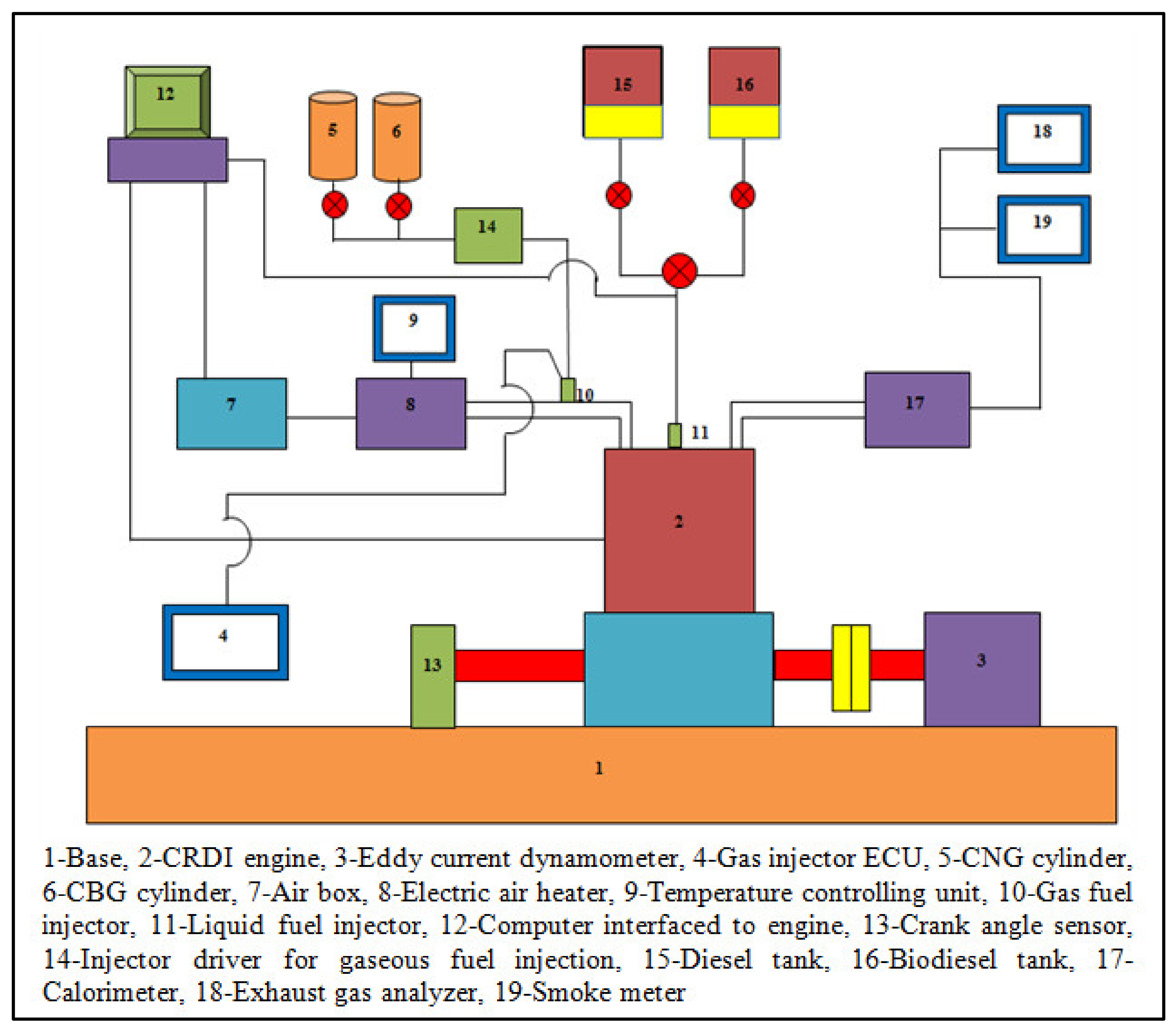
3. Experimental Setup

The complete experimental tests were carried out on a Kirloskar TV1 CRDI engine. The test engine was operated at 1500 rpm. An initial test was conducted with an injection of diesel to get baseline data. The existing engine was revised to RCCI mode by altering essential arrangements. During suction stroke, MIF such as CNG and CBG were injected at 5 bar IP into the inlet manifold so that these fuels were well mixed with suction air and well distributed in the cylinder. At compression stroke DIF as diesel, TPME B20, and TPME B100 were injected directly in the cylinder at 900 bar IP. Hence, there was the development of fuel reactivity inside the cylinder. The MIF is injected in the cylinder at different ITs such as 45° ATDC, 50° ATDC, and 55° ATDC. The constant ID of 3 ms of MIF is maintained to carryout the study of optimization of IT. Then, MIF are injected at different IDs such as 3, 6, and 9 ms. The optimized IT of 50° ATDC of MIF is maintained to carryout the study of optimization of ID. The complete experiments are carried out at constant IT of 10° BTDC of DIF, 40% gaseous fuels energy share (GFES), and 75% of rated power. An optimum value of GFES of 40% is arrived at by considering overall performance parameters from exhaustive experimental results. Hence, 40% GFES is kept constant for the current study. At 75% load condition, the effect of ID (varied from 3 to 9 ms) on RCCI performance is determined, keeping the energy ratio constant for the fuel combinations considered. To study the impact of ID on RCCI combustion, it is varied from 3 to 9 ms, in steps of 3 ms. As the ID increase from 3 to 9 ms, the gas flow rates also increase. Further, to achieve a constant GFES of 40% at the three IDs considered, the quantity of direct injected pilot fuels was changed accordingly for the engine operation at 75% load. The pilot fuel quantity is set using closed loop fuel mass set point (FMSP) with PID controlled fuel mass limit control factor.
The test engine is shown in Figure 1. Specifications of the experimental engine are provided in Table 4.
Brake thermal efficiency (BTE) expressed in percentage is calculated bythe following equation:
BTE = BP m f × CV LRF + m f × CV HRF
where,
  • BP = Brake power, kW
  • (mf × CV)LRF = Energy supplied by low reactive fuels, kW
  • (mf × CV)HRF = Energy supplied by high reactive fuels, kW
Further, gaseous fuels energy share (GFES) for RCCI mode of combustion is defined as the ratio of energy supplied by the low reactive fuels to the summation of energy supplied from low reactive fuels and high reactive fuels. It is expressed in terms of percentage and is determined by the following equation:
GFES = m f × CV LRF m f × CV LRF + m f × CV HRF
HC and CO emissions are measured with the help of an exhaust gas analyzer. The detailed information about the exhaust gas analyzer is given in Table 4.
Smoke emissions are measured by a Hartridge smoke meter. The detailed information about the smoke meter is given in Table 5.
For the combustion parameters analysis, 100 cycles of pressure-crank angle history were recorded. In order to minimize the errors of measurements, ten readings are recorded under steady-state engine operating conditions and averaged out results are only presented for the results and analysis.
HRR of the fuel causes a variation of cylinder gas pressure and temperature within the engine combustion chamber. It strongly affects fuel economy, brake power, and engine-out emissions. It provides an insight into the fuel combustion process. Calculation of HRR is very important, especially for engine research. A computer program was developed to obtain the HRR. The HRR was calculated by using a first law analysis of the average cylinder gas pressure versus crank angle variation obtained by using Equation (1) [42].
Qapp   = γ γ 1 p . dv   + 1 γ 1 v . dp   +   Qwall
where,
  • Qapp—Apparent heat release rate (J)
  • γ—Ratio of specific heats C p C p R
  • R—Gas constant (J/kmol-k)
  • Cp—Specific heat at constant pressure (J/kmol-k)
  • V—Instantaneous volume of the cylinder (m3)
  • P—Cylinder pressure (bar)
  • Qwall—Heat transfer to the wall (J)
For this calculation, cylinder gas was assumed to behave as an ideal gas (air) with specific heats being dependent on temperature. The specific heat was found using Equation (2).
Cp = 3.6359 1.33736   T 1000 + 3.29421   T 2 1 × 10 6 1.91142   T 3 1 × 10 9 + 0.275462   T 4 1 × 10 12 R
For T < 1000 °K
Cp = 3.04473 + 1.338056   T 1000 0.488256   T 2 1 × 10 6 + 0.0855475   T 3 1 × 10 9 0.00570127   T 4 1 × 10 12 R
For T > 1000 °K
Heat transferred to the wall was determined with the Hohenberg Equation (4) [43] and assuming the wall temperature to be 450 °C [42].
Qwall = h × A × Tg Tw
h = C ×   V 0 · 06 ×   P 0 · 8 ×   T 0 · 4 × Vp + C 0 · 8
where,
  • h—Heat transfer coefficient (W/m2K)
  • C1 and C2—Constants, 130 and 1.4
  • V—Cylinder volume (m3)
  • P—Cylinder pressure (bar)
  • T—Cylinder gas temperature (K)
  • Vp—Piston mean speed (m/s)
  • A—Instantaneous area (m2)
Positive and negative values of the HRR before 350° and after 390° CA could be due to the differences in the delay period associated with varied properties of the fuel combinations used. Further, the quantity of fuel participating in the premixed and diffusion combustion phase results in the variation of the magnitudes of the HRR values.

4. Results and Discussions

This section represents the combustion, emission, and performance characteristics of RCCI combustion operated with CNG and CBG as the MIF and diesel, TPME B20, and TPME B100 fuels as the DIF by varying ITs and IDs of MIF.

4.1. Analysis of Uncertainty

The error analysis of experimental data is calculated by using systematic calculations. The overall uncertainty is calculated using Equation (6).
Uy y = i = 1 n 1 y y xi 2
where
  • y—Specific factor which depends on the parameter xi
  • Uy—Level of uncertainties or variation in y
Overall   uncertainty = Uncertainty   %   of   ( Engine   speed 2 + CO   emission 2 + NOx   emission 2   + HC   emission 2 + Brake   thermal   efficiency 2 + Smoke   emission 2 = Uncertainty   %   of   ( 0.6 2 + 0.6 2 + 0.7 2 + 0.5 2 + 0.7 2 + 0.5 2 = ±   1.48

4.2. Effect of Manifold IT on the Performance of RCCI Combustion

In this segment, the influence of manifold ITs on the combustion, emission, and performance characteristics of RCCI combustion powered with CNG and CBG as MIF and diesel, TPME B20, and TPME B100 as DIF. The MIF are injected at different ITs such as 45° ATDC, 50° ATDC, and 55° ATDC. The DIF are injected at constant IT of 10° BTDC. In this work, a constant 40% gaseous fuel energy share is utilized to conduct the experiments. The constant ID of 3 ms of manifold injected fuels is maintained to carryout the study.
Figure 2 shows BTE variation with IT. As the IT increases from 45° ATDC to 50° ATDC the BTE also increases. The growth in BTE at advanced IT is due to enhanced combustion because of adequate time for improved mixing of fuel and air, resulting in higher premixed combustion. The retarded IT results in lower BTE because of less time available for the mixing of fuel and air. Again, as the IT increases from 50° ATDC to 55° ATDC the BTE decreases. At an IT of 55° ATDC, it may be noted that even though there is adequate time available for better mixing of fuel and air however the momentum with which the fuel particles accumulate inside the combustion chamber is more. This, in turn, results in improper combustion, which further leads to more amount of unburnt HC and CO emissions along with a reduction of BTE at an IT of 55° ATDC.
Maximum BTE 29.32% is observed for D+CNG mixture at 50° ATDC IT which is about 1.77, 3.58, 5.56, 7.51, and 8.54% higher than D+CBG, B20+CNG, B20+CBG, B100+CNG and B100+CBG fuel combinations. CNG exhibits more BTE related to CBG. Lower reactivity of CBG results in deficient combustion so that BTE for CBG is lower. RCCI combustion operated with TPME showed minimum BTE as related to pure diesel. Due to the higher viscosity and lower calorific value of TPME, it exhibits improper combustion and exhibits lower BTE at all ITs.
Figure 3 shows HC variation with IT. Among various ITs of MIF studied 50° ATDC gives fewer HC emissions. There is enough amount of accessibility of oxygen for better combustion of fuel so that it exhibits lower discharge of HC emissions. D+CNG mixture leads to less quantity of HC emissions. Proper ignition of CNG by diesel increases the BTE and decreases the emissions of HC. TPME powered RCCI combustion exhibits more number of HC emissions. The clumsy structure of TPME molecules yields a loss of fuel particles due to excessive wall impingement and hence HC emissions are lower for TPME.
Figure 4 presents CO variation with IT. Lower emissions of CO are observed at 50° ATDC IT as compared with 45° ATDC and 55° ATDC. This is due to, at 50° ATDC IT, there is sufficient time for available oxygen to contact with the fuel particles so that proper burning of the fuel particles is formed that yields a fewer amount of CO emissions. D+CNG fuel mixture exhibits less number CO emissions as compared with other fuel mixtures. RCCI engine powered with pure diesel results in less CO emissions as related with TPME. This is because diesel has greater calorific value and leads to stratified combustion so that emissions of CO are less.
Figure 5 shows NOx variation with IT. Among various, ITs studied 50° ATDC gives higher NOx emissions as compared with 45° ATDC and 55° ATDC. At 50° ATDC IT BTE of the RCCI engine operated with any type of fuel combination is increased, which means higher HRR inside the cylinder, which inturn increases the NOx emissions. For the D+CNG mixture, higher emissions of NOx are observed. The formation of rich combustion as CNG fuel injected as the manifold injected fuel with diesel as the direct injected fuel. Fewer emissions of NOx are observed for TPME operation. This is due to the lean mixture formation inside the cylinder when biodiesel is injected as pilot fuel.
Figure 6 shows smoke variation with IT. For RCCI combustion mode, very low levels of smoke emissions are obtained. IT of 50° ATDC exhibits a fewer amount of smoke as related to 45° ATDC and 55° ATDC. There is a formation of a homogeneous mixture of fuel and air at 50° ATDC IT could be the reason for lower smoke emissions. D+CNG results from less quantity of smoke than other fuel mixtures. Stratified combustion takes place when CNG is injected into the cylinder as low reactive fuel along with diesel as high reactive fuel, which is injected as pilot fuel. TPME operated RCCI combustion showed more quantity of smoke than diesel. Poor combustion characteristics of TPME injected RCCI combustion exhibits a large quantity of smoke emissions.
Figure 7 shows ICP variation with fuel combination at different IT. The highest ICP values are taken to draw the graphs. At all ITs higher ICP is obtained for D+CNG fuel combination. Higher reactivity inside the combustion chamber when CNG is injected as LRF along with diesel is injected as HRF. Due to this reactivity, a high temperature of combustion gas is released, which inturn results in higher ICP. The engine fueled with biodiesel shows a lower rate of ICP rise as compared with diesel. Non-homogeneous mixture formation of biodiesel along with manifold injected fuels leads to lean combustion, and hence the rate of ICP rise decreases for biodiesel.
Figure 8 HRR variation with CA at different ITs. Among various fuel combinations, D+CNG shows higher HRR as related toother combinations of fuels. Uniform and stratified combustion due to highly premixed CNG burns effectively when diesel injected as pilot injected fuel, so that the amount of energy generated is more inside the cylinder, resulting in higher HRR for D+CNG fuel combination. The engine fueled with CBG results in lower HRR as compared with CNG. This is due to, lower reactivity of combustible mixture when CBG is added into any pilot fuel. The biodieselfueled RCCI engine showed lower HRR as compared with diesel. The biodiesel fueled engine shows large excessive wall impingement and hence the HRR for biodiesel is lower.

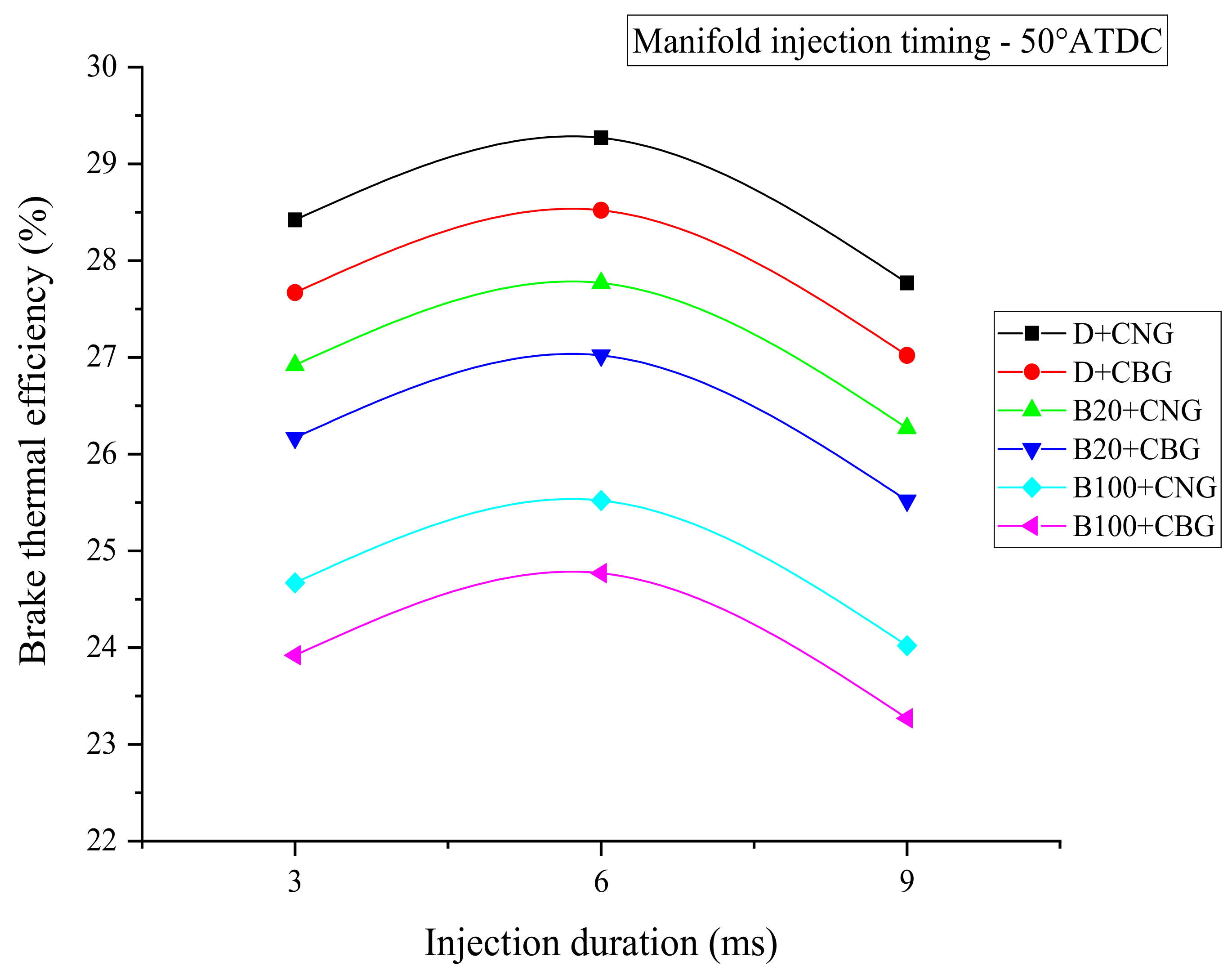
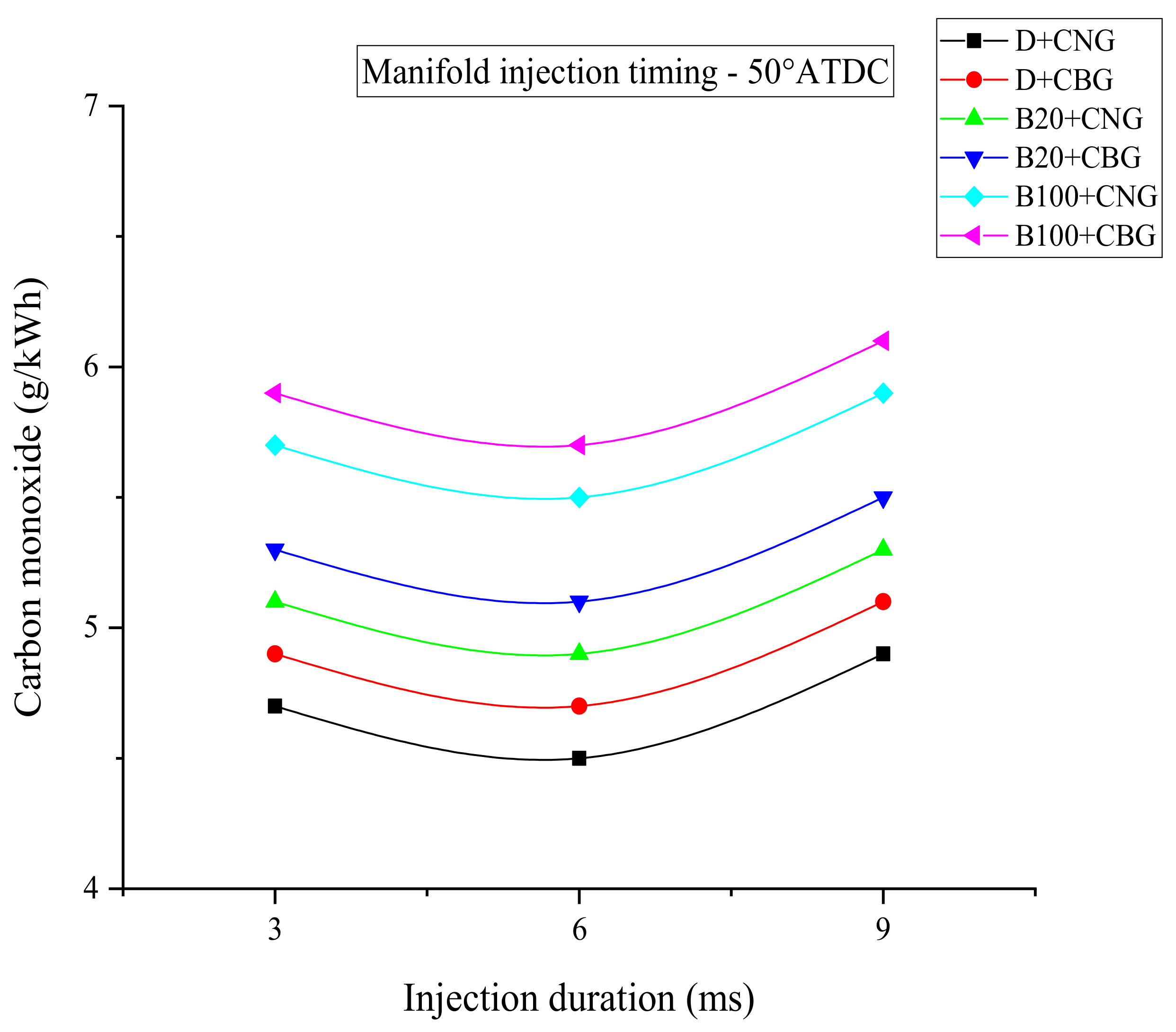
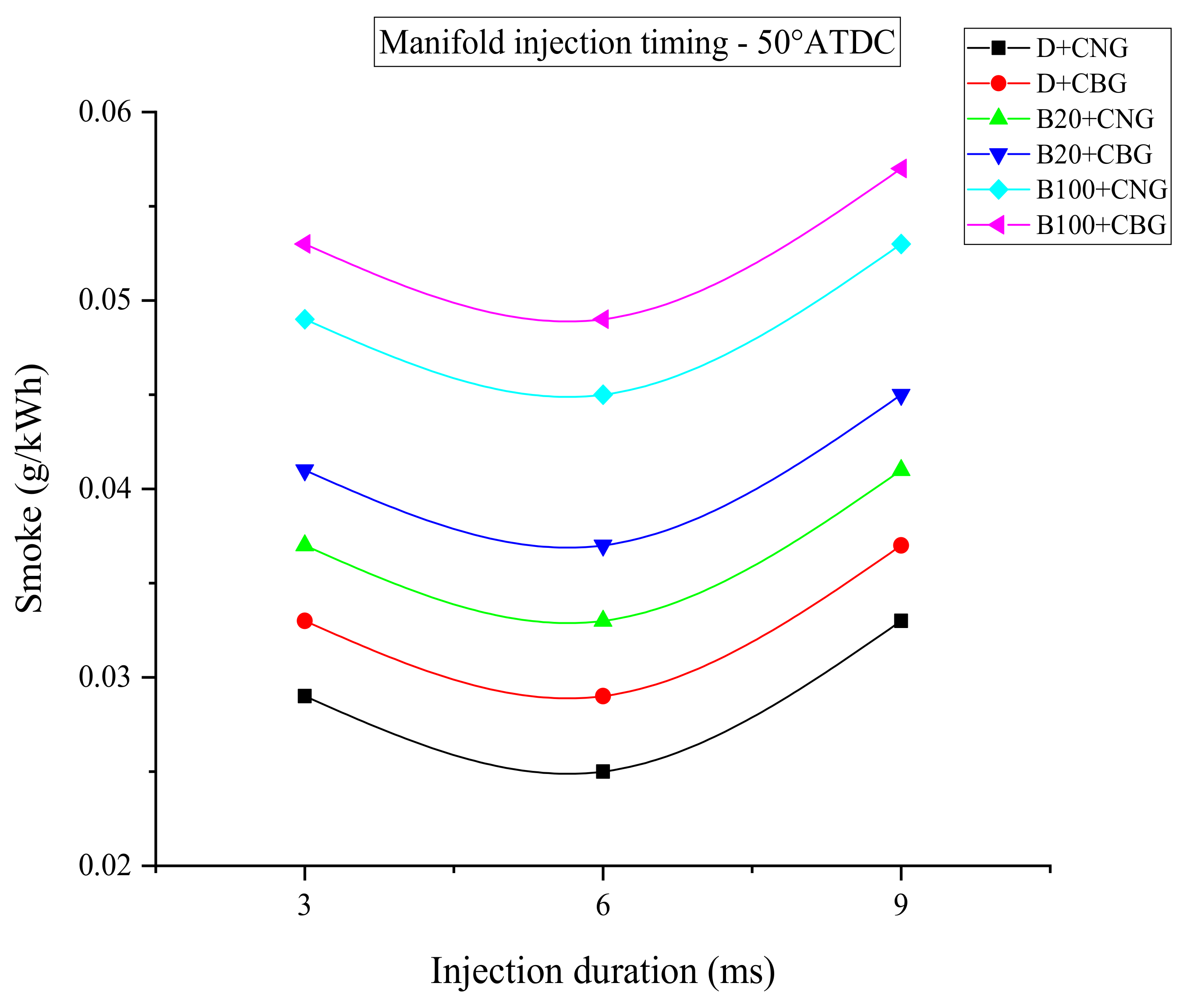
4.3. Effect of Manifold ID

The effect of manifold ID on the combustion, emission, and performance characteristics of RCCI combustion operated by CNG and CBG as MIF and diesel, TPME B20, and TPME B100 blends as DIF is discussed in this section. The MIF is injected at different IDs such as 3, 6, and 9 ms. The DIF is injected at a constant IT of 10° BTDC. In this work, a constant 40% gaseous fuel energy share is utilized to conduct the experiments. The constant IT of 50° ATDC of MIF is maintained to carryout the study.
Figure 9 shows BTE variation with ID. Among various IDs 6 ms gives better performance in terms of BTE. Though in dual-fuel combustion, the ignition of the pilot fuel gets retarded by the premixed fuel-air mixture formation. In contrast to this, as the engine is operated in RCCI mode with different fuel combinations of low and high reactive fuels, the observed trends are different compared to dual-fuel operation. Accordingly, as the ID increases from 3 to 6 ms, there is sufficient availability of fuel and air to form a stratified mixture that gets easily ignited by the pilot fuel. Due to this BTE increased for 6 ms ID. As the ID increased from 6 to 9 ms the decrease of BTE is observed. A large quantity of fuel particles collected inside the cylinder when ID increased from 6 to 9 ms, which leads to improper combustion, and hence BTE decreased. The highest BTE, about 30.25%, is found for D+CNG fuel combination at 6 ms ID which is about 1.69, 3.48, 5.32, 7.24, and 9.16% higher as compared with D+CBG, B20+CNG, B20+CBG, B100+CNG, and B100+CBG fuel combinations. RCCI combustion with biodiesel shows lower BTE as related to pure diesel. The calorific value of the biodiesel is less, which results in lower energy generated inside the chamber and hence BTE for biodiesel fueled RCCI engine is lower.
Figure 10 shows HC variation with ID. The lowest HC emissions are observed at 6 ms ID as compared with other manifold IDs. Proper reactivity gradient is generated inside the combustion chamber when ID increased from 3 to 6 ms due to that HC emissions are lower for 6 ms ID. The D+CNG results in fewer HC emissions for various combinations of fuels tested. There is a formation of a rich mixture when CNG ignites with the help of diesel. For this reason, emissions of HC are lower for the D+CNG mixture. CBG as low reactive fuel shows a higher rate of HC as compared with CNG since low reactive fuel. CBG exhibits poor ignition quality compared with CNG, and hence HC emissions are higher for CBG as low reactive fuel. The TPME fueled engine shows a higher quantity of HC emissions. Greater viscosity and density of TPME result in improper atomization of fuel particles and hence emissions of HC are more for the TPME fueled RCCI engine.
Figure 11 shows CO variation with ID. Among the various manifold IDs studied, 6 ms ID provides fewer emissions of CO as related to 3 and 9 ms ID. Efficient and stratified combustion of low reactive fuel and high reactive fuel inside the chamber at 6 ms ID leads to lower CO emissions. From various fuel mixtures studied, D+CNG results in less CO emissions. CNG as premixed fuel distributed evenly in the cylinder and properly ignited by diesel due to that emission of CO are less for D+CNG fuel combination. Biodiesel exhibit higher emissions of CO as compared to diesel. The molecular arrangement of TPME is heavier hence undergoes improper combustion which results in higher CO emissions for biodiesel.
Figure 12 shows NOx variation with ID. The 6 ms ID results ina higher rate of NOx emissions as related todifferent IDs. At 6 ms ID, higher BTE is obtained, which means there is efficient combustion that leads to greater combustion temperature so that NOx emissions are high at 6 ms ID. The D+CNG combination of fuel exhibits a higher number of NOx emissions as related to other combinations of fuels. As a pilot fuel, diesel atomizes well and becomes fine spray when it comes out of the nozzle and ignites CNG properly so that emissions of NOx are higher for the D+CNG mixture. RCCI engine exhibits lower NOx emissions when fueled with biodiesel. Biodiesel showed poor ignition characteristics, and hence NOx emissions for biodiesel fueled engines are lower.
Figure 13 shows smoke variation with ID. The 6 ms ID gives enhanced results in case of lower emissions of smoke as related with 3 ms and 9 ms ID. At the optimum ID, sufficient oxygen availability around the fuel particles is more; hence effective combustion takes place so that smoke emissions are low for 6 ms ID. The D+CNG mixture exhibits fewer emissions of smoke as related toother combinations of fuels. CNG as low reactive fuel has better ignition quality along with diesel as high reactive fuel and hence D+CNG fuel combination leads to lower smoke emissions. The biodiesel fueled RCCI engine shows inferior results as compared with diesel. This is due to the high thermal stability of biodiesel that leads to improper combustion which results in higher smoke emissions as compared with diesel.
Figure 14 shows ICP variation with CA at different IDs. The highest ICP values are taken to draw the graphs. The D+CNG fuel combination gives a higher ICP rise as related toother combinations of fuels. Higher thermal efficiency of this fuel mixture leads to the rise of temperature inside the cylinder and hence ICP rise for D+CNG fuel combination. ICP rise for biodiesel-fueled engines is lower as related with pure diesel. The sticky nature and heavier molecular structure of biodiesel lead to a lower ICP rise as compared with diesel.
Figure 15 shows HRR variation with the crank angle at different IDs. Among various fuel combinations, D+CNG leads to a higher HRR as related toother fuel combinations. The higher pressure rise rate of the mixture leads to a higher HRR inside the combustion chamber. The HRR for the biodiesel fueled RCCI engine is lower as compared with diesel. Greater viscosity and the lower heating value of methyl ester lead to lower combustion temperature, leading to lower HRR.

5. Conclusions

The effect IT and ID of manifold injected fuels in RCCI engine powered with CNG and CBG as low reactive fuels and TPME and diesel as high reactive fuels has been studied. The main findings from the experimentation are explained in the following:
  • At all IT studied D+CNG fuel combination results into higher BTE 29.32% at 50° ATDC IT which is about 1.77, 3.58, 5.56, 7.51, and 8.54% higher than D+CBG, B20+CNG, B20+CBG, B100+CNG and B100+CBG fuel combinations.
  • The highest BTE, about 30.25%, is found for D+CNG fuel combination at 6 ms ID which is about 1.69, 3.48, 5.32, 7.24, and 9.16% higher as compared with D+CBG, B20+CNG, B20+CBG, B100+CNG, and B100+CBG fuel combinations.
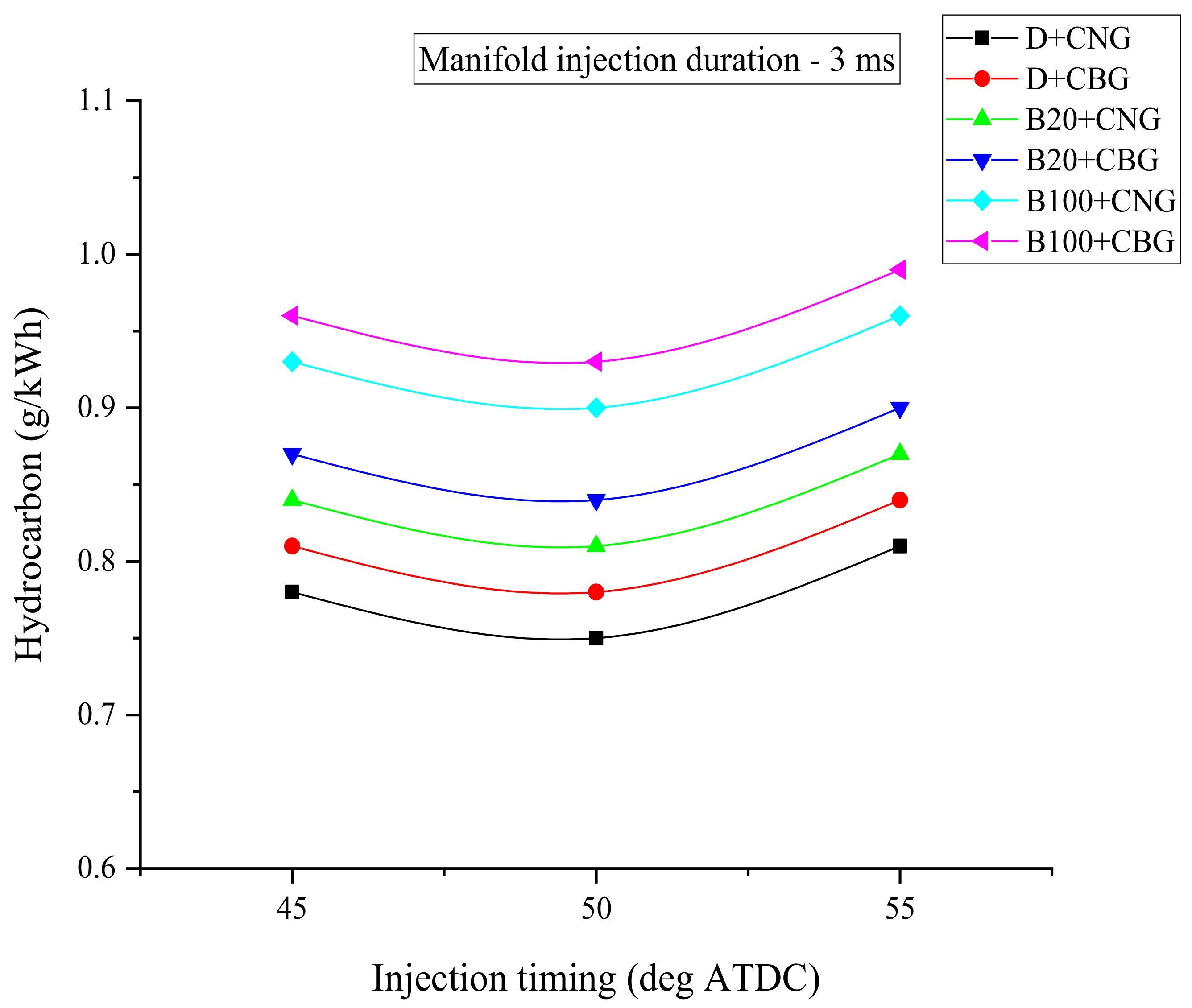
  • At all ITs and IDs tested lower emissions of smoke, CO, and HC emissions and also higher emissions of NOx are observed for the D+CNG combination of fuel as related toother combinations of fuels.
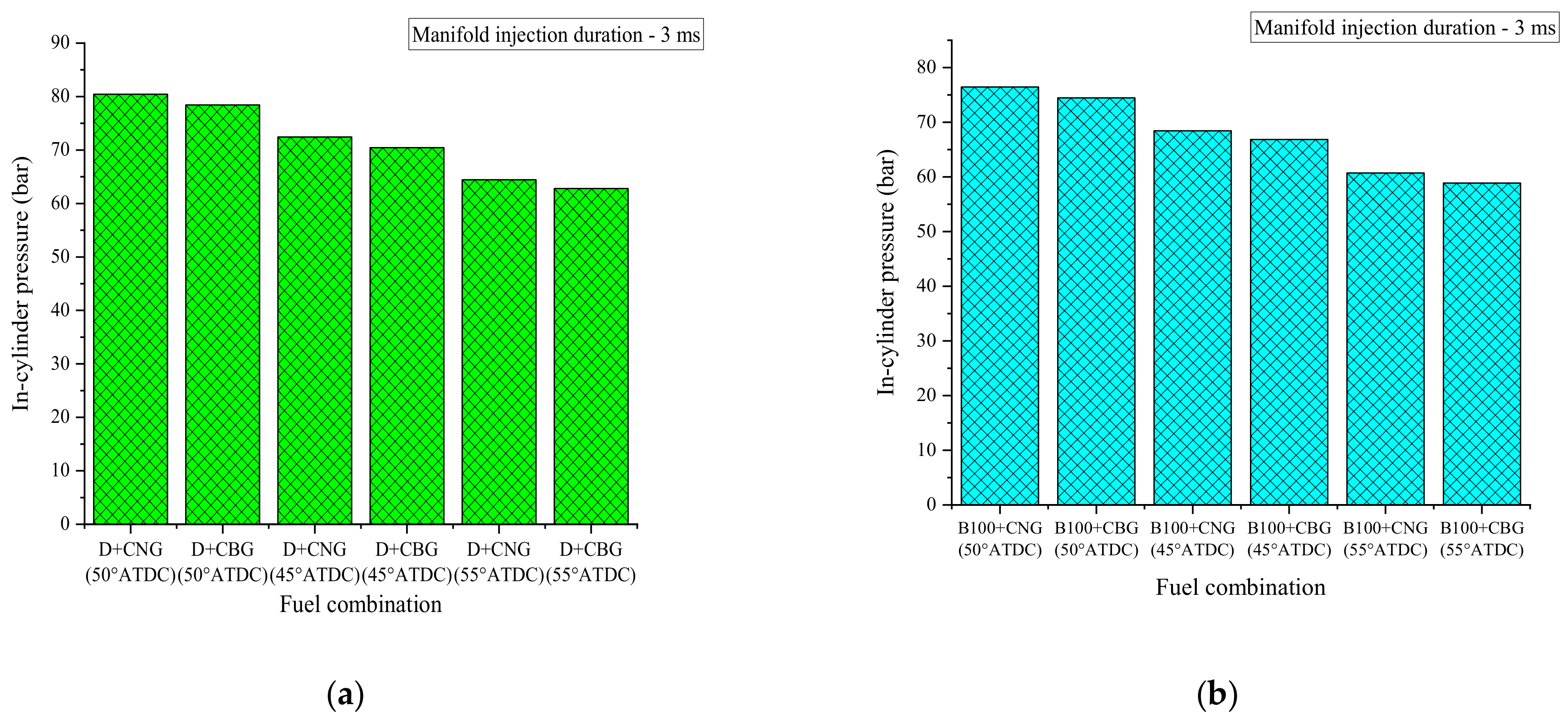
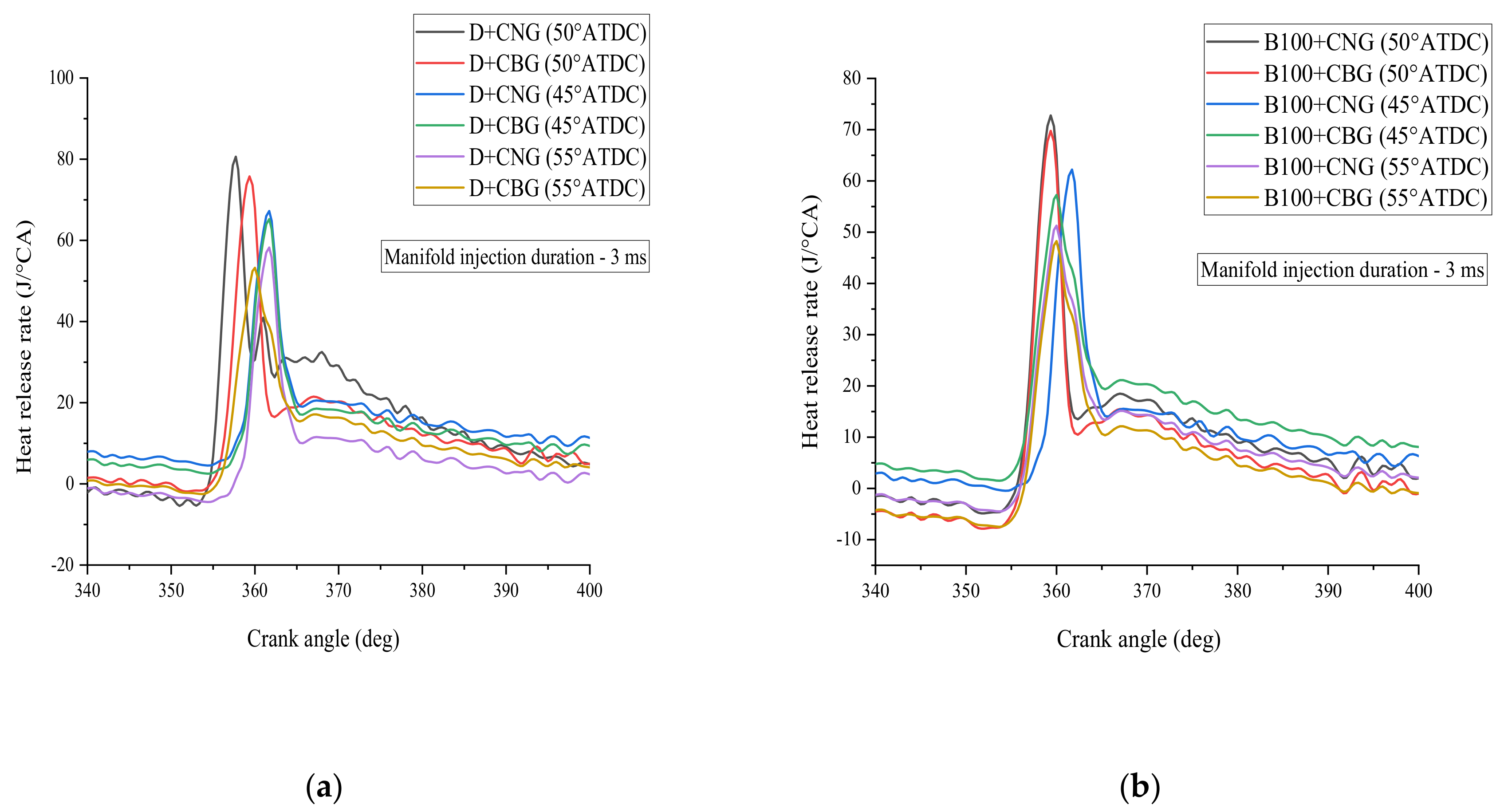
  • At all ITs and IDs, D+CNG gives higher ICP and HRR as related to other combinations of fuels.
The injection of CNG and CBG in the RCCI operation as manifold injected fuels along with diesel, TPME B20, and TPME B100 fuels as direct injected fuels has been performed from the experimental work. The effect of IT and ID of manifold injected fuels is studied in the current work. The 50° ATDC IT gives effective results based on efficiency and emissions as compared with other ITs. Among the various IDs, 6 ms gives optimized results based on efficiency and emissions as compared with other IDs.

Author Contributions

Conceptualization, P.A.H. and N.R.B.; methodology, N.R.B.; validation, V.S.Y., T.M.Y.K. and I.A.B.; formal analysis, N.R.B.; investigation, N.R.B. and P.A.H.; resources, T.M.Y.K. and S.K.; writing—original draft preparation, P.A.H.; writing—review and editing, T.M.Y.K., I.A.B. and T.M.I.M.; visualization, S.K.; supervision, N.R.B.; funding acquisition, T.M.I.M. and I.A.B. All authors have read and agreed to the published version of the manuscript.

Funding

This research was funded by King Khalid University, grant number (R.G.P 2/147/42).

Institutional Review Board Statement

Not applicable.

Informed Consent Statement

Not applicable.

Data Availability Statement

Not applicable.

Acknowledgments

The authors extend their appreciation to the Deanship of Scientific Research at King Khalid University for funding this work through a research groups program under grant number (R.G.P 2/147/42).

Conflicts of Interest

The authors declare no conflict of interest.

References

  1. Li, H.; Shi, L.; Deng, K. Development of turbocharging system for diesel engines of power generation application at different altitudes. J. Energy Inst. 2016, 89, 755–765. [Google Scholar] [CrossRef]
  2. Shelar, M.N.; Bagade, S.D.; Kulkarni, G.N. Energy and Exergy Analysis of Diesel Engine Powered Trigeneration Systems. Energy Proc. 2016, 90, 27–37. [Google Scholar] [CrossRef]
  3. Seifi, M.R.; Hassan-Beygi, S.R.; Ghobadian, B.; Desideri, U.; Antonelli, M. Experimental investigation of a diesel engine power, torque and noise emission using water-diesel emulsions. Fuel 2016, 166, 392–399. [Google Scholar] [CrossRef]
  4. Silitonga, A.S.; Masjuki, H.H.; Ong, H.C.; Sebayang, A.H.; Dharma, S.; Kusumo, F.; Siswantoro, J.; Milano, J.; Daud, K.; Mahlia, T.M.I.; et al. Evaluation of the engine performance and exhaust emissions of biodiesel-bioethanol-diesel blends using kernel-based extreme learning machine. Energy 2018, 159, 1075–1087. [Google Scholar] [CrossRef]
  5. Ong, H.C.; Masjuki, H.H.; Mahlia, T.M.I.; Silitonga, A.S.; Chong, W.T.; Leong, K.Y. Optimization of biodiesel production and engine performance from high free fatty acid Calophylluminophyllum oil in CI diesel engine. Energy Convers. Manag. 2014, 81, 30–40. [Google Scholar] [CrossRef]
  6. Silitonga, A.S.; Mahlia, T.M.I.; Kusumo, F.; Dharma, S.; Sebayang, A.H.; Sembiring, R.W.; Shamsuddin, A.H. Intensification of Reutealistrisperma biodiesel production using infrared radiation: Simulation, optimisation and validation. Renew. Energy 2019, 133, 520–527. [Google Scholar] [CrossRef]
  7. Hoseini, S.S.; Najafi, G.; Ghobadian, B.; Mamat, R.; Sidik, N.A.C.; Azmi, W.H. The effect of combustion management on diesel engine emissions fueled with biodiesel-diesel blends. Renew. Sustain. Energy Rev. 2017, 73, 307–331. [Google Scholar] [CrossRef] [Green Version]
  8. Asokan, M.A.; Senthurprabu, S.; Kamesh, S.; Khan, W. Performance, combustion and emission characteristics of diesel engine fuelled with papaya and watermelon seed oil bio-diesel/diesel blends. Energy 2018, 145, 238–245. [Google Scholar] [CrossRef]
  9. Hossain, F.M.; Rainey, T.J.; Ristovski, Z.; Brown, R.J. Performance and exhaust emissions of diesel engines using microalgae FAME and the prospects for microalgae HTL biocrude. Renew. Sustain. Energy Rev. 2018, 82, 4269–4278. [Google Scholar] [CrossRef] [Green Version]
  10. Ong, H.C.; Milano, J.; Silitonga, A.S.; Hassan, M.H.; Shamsuddin, A.H.; Wang, C.T.; Mahlia, T.M.I.; Siswantoro, J.; Kusumo, F.; Sutrisno, J. Biodiesel production from Calophylluminophyllum-Ceiba pentandra oil mixture: Optimization and characterization. J. Clean. Prod. 2019, 219, 183–198. [Google Scholar] [CrossRef]
  11. Rahman, S.M.A.; Fattah, I.M.R.; Maitra, S.; Mahlia, T.M.I. A ranking scheme for biodiesel underpinned by critical physicochemical properties. Energy Convers. Manag. 2021, 229, 113742. [Google Scholar] [CrossRef]
  12. Bhuiya, M.M.K.; Rasul, M.G.; Khan, M.M.K.; Ashwath, N.; Azad, A.K.; Hazart, M.A. Prospects of 2nd generation biodiesel as a sustainable fuel—Part 2: Properties, performance and emission characteristics. Renew. Sustain. Energy Rev. 2016, 55, 1129–1146. [Google Scholar] [CrossRef]
  13. Jahirul, M.I.; Rasul, M.G.; Brown, R.J.; Senadeera, W.; Hosen, M.A.; Haque, R.; Saha, S.C.; Mahlia, T.M.I. Investigation of correlation between chemical composition and properties of biodiesel using principal component analysis (PCA) and artificial neural network (ANN). Renew. Energy 2021, 168, 632–646. [Google Scholar] [CrossRef]
  14. Duraisamy, M.K.; Balusamy, T.; Senthilkumar, T. Effect of compression ratio on CI engine fueled with methyl ester of thevetia peruviana seed oil. ARPN J. Eng. Appl. Sci. 2012, 7, 229–234. [Google Scholar]
  15. Sutar, A.; Bhatkande, R.; Gurav, R.; Mulla, M.; Deokar, A.; Harari, P. Experimental studies on production of biodiesel from thevetia peruviana feedstock. Int. J. Eng. Manag. Res. 2018, 8, 46–49. [Google Scholar]
  16. Deokar, A.J.; Harari, P.A. Effect of injection pressure, injection timing and nozzle geometry on performance and emission characteristics of diesel engine operated with thevetia peruviana biodiesel. Mater. Today Proc. 2021. [Google Scholar] [CrossRef]
  17. Harari, P.A.; Deokar, A.J.; Sutar, A.S.; Patil, A.K.; Patil, S.D.; Patil, S.S. Comparison of various B20 biodiesel blends in diesel engines. Int. J. Res. Advent Technol. 2019, 7, 294–305. [Google Scholar] [CrossRef]
  18. Harari, P.A.; Yaliwal, V.S.; Banapurmath, N.R. Experimental studies on RCCI engine powered with n-butanol and thevetia peruviana methyl ester. In Techno-Societal; Springer: Berlin/Heidelberg, Germany, 2020. [Google Scholar] [CrossRef]
  19. Deokar, A.J.; Harari, P.A.; Sutar, S.E.; Hodage, P.P.; Patil, J.V.; Kole, A.R. Effect of nozzle hole geometry on compression ignition engine fuelled with thevetia peruviana biodiesel. Int. J. Innovative Res. Sci. Eng. Technol. 2018, 7, 11861–11871. [Google Scholar] [CrossRef] [Green Version]
  20. Harari, P.A.; Banapurmath, N.R.; Yaliwal, V.S.; Soudagar, M.E.M.; Khan, T.M.; Mujtaba, M.A.; Safaei, M.R.; Akram, N.; Goodarzi, M.; Elfasakhany, A.; et al. Experimental investigation on compression ignition engine powered with pentanol and thevetia peruviana methyl ester under reactivity controlled compression ignition mode of operation. Case Stud. Therm. Eng. 2021, 25, 100921. [Google Scholar] [CrossRef]
  21. Harari, P.A.; Banapurmath, N.R.; Yaliwal, V.S.; Khan, T.M.; Soudagar, M.E.M.; Sajjan, A.M. Experimental studies on performance and emission characteristics of reactivity controlled compression ignition (RCCI) engine operated with gasoline and thevetia peruviana biodiesel. Renew. Energy 2020, 160, 865–875. [Google Scholar] [CrossRef]
  22. Walker, N.R.; Chuahy, F.D.F.; Reitz, R.D. Comparison of diesel pilot ignition (DPI) and reactivity controlled compression ignition (RCCI) in a heavy-duty engine. In Proceedings of the ASME 2015 Internal Combustion Engine Division Fall Technical Conference, Houston, TX, USA, 8–11 November 2015. [Google Scholar]
  23. Wissink, M.; Reitz, R.D. Direct dual fuel stratification, a path to combine the benefits of RCCI and PPC. SAE Int. J. Engines 2015, 8, 878–889. [Google Scholar] [CrossRef]
  24. Noehre, C.; Andersson, M.; Johansson, B.; Hultqvist, A. Characterization of Partially Premixed Combustion; SAE Technical Paper; SAE: Warrendale, PA, USA, 2006. [Google Scholar]
  25. Kalghatgi, G.T.; Risberg, P.; Angstrom, H.E. Advantages of Fuels with High Resistance to Auto-Ignition in Late-Injection, Low-Temperature, Compression Ignition Combustion; SAE Technical Paper; SAE: Warrendale, PA, USA, 2006. [Google Scholar]
  26. Sellnau, M.C.; Sinnamon, J.; Hoyer, K.; Husted, H. Full-time gasoline direct-injection compression ignition (GDCI) for high efficiency and low NOx and PM. SAE Int. J. Engines 2012, 5, 300–314. [Google Scholar] [CrossRef]
  27. Kalghatgi, G.T.; Risberg, P.; Ångström, H.E. Partially Pre-Mixed Auto-Ignition of Gasoline to Attain Low Smoke and Low NOx at High Load in A Compression Ignition Engine and Comparison with a Diesel Fuel; SAE Technical Paper; SAE: Warrendale, PA, USA, 2007. [Google Scholar]
  28. Kokjohn, S.L.; Reitz, R.D. An investigation of charge preparation strategies for controlled PPCI combustion using a variable pressure injection system. Int. J. Eng. Res. 2010, 11, 257–282. [Google Scholar] [CrossRef]
  29. Lu, X.; Han, D.; Huang, Z. Fuel design and management for the control of advanced compression-ignition combustion modes. Prog. Energy Combust. Sci. 2011, 37, 741–783. [Google Scholar] [CrossRef]
  30. Paykani, A.; Kakaee, A.H.; Rahnama, P.; Reitz, R.D. Progress and recent trends in reactivity-controlled compression ignition engines. Int. J. Engine Res. 2016, 17, 481–524. [Google Scholar] [CrossRef]
  31. Benajes, J.; Garcia, A.; Serrano, J.M.; Sari, R. Potential of RCCI series hybrid vehicle architecture to meet the future CO2 targets with low engine-out emissions. Appl. Sci. 2018, 8, 1472. [Google Scholar] [CrossRef] [Green Version]
  32. Solouk, A.; Shahbakhti, M. Energy optimization and fuel economy investigation of a series hybrid electric vehicle integrated with Diesel/RCCI engines. Energies 2016, 9, 1020. [Google Scholar] [CrossRef] [Green Version]
  33. Kousheshi, N.; Yari, M.; Paykani, A.; Mehr, A.S.; Fuente, G.F. Effect of syngas composition on the combustion and emissions characteristics of a syngas/diesel RCCI engine. Energies 2020, 13, 212. [Google Scholar] [CrossRef] [Green Version]
  34. Mahmoodi, R.; Yari, M.; Ghafouri, J.; Poorghasemi, K. Effect of reformed biogas as a low reactivity fuel on performance and emissions of a RCCI engine with reformed biogas/diesel dual-fuel combustion. Int. J. Hydrog. Energy 2021. [Google Scholar] [CrossRef]
  35. Harari, P.A.; Yaliwal, V.S.; Banapurmath, N.R. Effect of CNG and CBG as low reactivity fuels along with diesel and TPME as high reactivity fuels in RCCI mode of combustion by varying different loads. Mater. Today Proc. 2021. [Google Scholar] [CrossRef]
  36. Dalha, I.B.; Said, M.A.; Karim, Z.A.A.; Mohammed, S.E. An experimental investigation on the influence of port injection at valve on combustion and emission characteristics of B5/Biogas RCCI engine. Appl. Sci. 2020, 10, 452. [Google Scholar] [CrossRef] [Green Version]
  37. Owczuk, M.; Matuszewska, A.; Kruczynski, S.; Kamela, W. Evaluation of using biogas to supply the dual fuel diesel engine of an agricultural tractor. Energies 2019, 12, 71. [Google Scholar] [CrossRef] [Green Version]
  38. Meng, X.; Meng, S.; Cui, J.; Zhou, Y.; Long, W.; Bi, M. Throttling effect study in the CDF/RCCI combustion with CNG ignited by diesel and diesel/biofuel blends. Fuel 2020, 279, 118454. [Google Scholar] [CrossRef]
  39. Chala, G.T.; Aziz, A.R.A.; Hagos, F.Y. Natural gas engine technologies: Challenges and energy sustainability issue. Energies 2018, 11, 2934. [Google Scholar] [CrossRef] [Green Version]
  40. Jamrozik, A.; Tutak, W.; Rogalinski, K.G. An experimental study on the performance and emission of the diesel/CNG dual fuel combustion mode in a stationary CI engine. Energies 2019, 12, 3857. [Google Scholar] [CrossRef] [Green Version]
  41. Rimkus, A.; Stravinskas, S.; Matijosius, J. Comparative study on the energetic and ecologic parameters of dual fuels (Diesel–NG and HVO–Biogas) and conventional diesel fuel in a CI engine. Appl. Sci. 2020, 10, 359. [Google Scholar] [CrossRef] [Green Version]
  42. Hayes, T.K.; Savage, L.; Soreson, S. Cylinder Pressure Data Acquisition and Heat Release Analysis on a Personal Computer. Soc. Automotive Eng. Tech. Paper 1986. Paper No. 860029. [Google Scholar] [CrossRef]
  43. Hohenberg, G.F. Advanced approaches for heat transfer calculations. Soc. Automotive Eng. Tech. Paper 1979. Paper No. 790825. [Google Scholar] [CrossRef]
Figure 1. RCCI experimental set-up.
Energies 14 04621 g001
Figure 2. Variation of BTE with IT.
Energies 14 04621 g002
Figure 3. Variation of HC emissions with IT.
Energies 14 04621 g003
Figure 4. Variation of CO emissions with IT.
Energies 14 04621 g004
Figure 5. Variation of NOx emissions with IT.
Energies 14 04621 g005
Figure 6. Variation of Smoke emissions with IT.
Energies 14 04621 g006
Figure 7. Variation of ICP with fuel combination at different ITs. (a) Variation of ICP with fuel combination for diesel as DIF. (b) Variation of ICP with fuel combination for B100 as DIF.
Energies 14 04621 g007
Figure 8. Variation of HRR with crank angle (CA) at different ITs. (a). Variation of HRR with CA for diesel as DIF. (b). Variation of HRR with CA for B100 as DIF.
Energies 14 04621 g008
Figure 9. Variation of BTE with ID.
Energies 14 04621 g009
Figure 10. Variation of HC emissions with ID.
Energies 14 04621 g010
Figure 11. Variation of CO emissions with ID.
Energies 14 04621 g011
Figure 12. Variation of NOx emissions with ID.
Energies 14 04621 g012
Figure 13. Variation of Smoke emissions with ID.
Energies 14 04621 g013
Figure 14. Variation of ICP with fuel combination at different IDs. (a) Variation of ICP with fuel combination for diesel as DIF. (b) Variation of ICP with fuel combination for B100 as DIF.
Energies 14 04621 g014
Figure 15. Variation of HRR with CA at different IDs. (a) Variation of HRR with CA for diesel as DIF. (b) Variation of HRR with CA for B100 as DIF.
Energies 14 04621 g015
Table 1. Properties of liquid fuels.
Fuels/PropertiesDieselTPME B20TPME B100
Specific gravity0.8290.8390.892
Kinematic viscosity (mm2/s)3.523.965.748
Flash point (°C)5377178
Calorific value (CV) (MJ/kg)42.1941.4539.46
Table 2. Properties of gaseous fuels [41].
PropertiesNatural GasBiogas
Cetane number--
Octane number>120130
Lower heating value (MJ/kg)50.019.1
Auto-ignition temperature (°C)650600–650
Stoichiometric air–fuel ratio17.2 6.17
Carbon content (%)75-
Flammability limits (vol.% in air)5–157.5–14
Table 3. Engine specifications.
Engine ParametersSpecifications
EngineTV1 Kirloskar
Cylinders1
SoftwareEngine soft
Strokes4
Compression ratio17.5:1
Cylinder bore (mm)87.5
Stroke (mm)110
Combustion chamberToroidal
DynamometerEddy current
Engine rated power (kW)5.2
Direct injection pressure (bar)900
Manifold injection pressure (bar)5
Table 4. Specifications of exhaust gas analyzer.
TypeDelta 1600S
Object of measurementCarbon monoxide (CO) and hydrocarbons (HC)
Warm up time10 min (self-controlled) at 20 °C
Accuracy±2% relative
Speed of response timeWithin 15 s for 90% response
SamplingDirectly sampled from tail pipe
Power source100–240 V AC/50 Hz
Weight800 g
Size100 mm × 210 mm × 50 mm
Table 5. Specifications of smoke meter.
TypeHartridge Smoke Meter
Object of measurementSmoke
Measuring range opacity0–100%
Accuracy±2% relative
Resolution0.1%
Smoke length0.43 m
Ambient temperature range−5 °C to +45 °C
Warm up time10 min (self-controlled) at 20 °C
Speed of response timeWithin 15 s for 90% response
SamplingDirectly sampled from tail pipe
Power supply100–240 V AC/50 HZ
10–16 V DC @15 amps
Size100 mm × 210 mm × 50 mm
Publisher’s Note: MDPI stays neutral with regard to jurisdictional claims in published maps and institutional affiliations.

