Article

An Insight to the Degradation Behaviour of the Parallel Connected Lithium-Ion Battery Cells

1
WMG, University of Warwick, Coventry CV4 7AL, UK
2
A123 Systems, University of Warwick, Coventry CV4 7EZ, UK
*
Author to whom correspondence should be addressed.
Energies 2021, 14(16), 4716; https://doi.org/10.3390/en14164716
Submission received: 16 July 2021 / Revised: 31 July 2021 / Accepted: 3 August 2021 / Published: 4 August 2021
(This article belongs to the Special Issue Battery Safety Diagnostics for Aerospace Electrification)

Abstract

:
In an electric vehicle, a large number of lithium-ion cells are connected in parallel. While cells in parallel increase the reliability of the battery pack, it increases the probability of current imbalance between the parallel branches, thus ageing gradient. The current peak in a cell also can exceed the maximum charge current capability of the cell; leading to lithium plating, therefore a safety issue. The temperature gradient within a battery pack amplifies this issue. This work reports the impact of such temperature gradient on current imbalance within parallel connected cells, their long-term impact on degradation and evaluation of current distribution with degradation. Employing a real-world relevant experimental setup, a total of 1400 cycles were performed on a module with four cells in parallel. A temperature gradient of 10 °C was introduced among the cells, and current in individual parallel branches was measured employing Hall-effect sensors. Over the course of the experiment, module capacity decreased by 23.6%. Cells at higher temperature/lower exposure to active cooling experienced higher degradation. However, the cell with the lowest starting capacity, although exposed to nominal module temperature and cooling experienced the highest current amplitude towards the end of discharge/charge and thus the highest resistance degradation. It was found that current in an individual parallel branch was exceeding the maximum rated charge/discharge current by 53%.

1. Introduction

Since their introduction, a large number of lithium-ion battery cell degradation studies have been performed and reviewed [1,2,3]. Thanks to these studies, we now have a good understanding of lithium-ion battery cell degradation mechanisms and the effect of different stress factors on these mechanisms. Almost all of the degradation studies were performed on battery cells or individual cells. Battery models are commonly developed utilizing this understanding, and models are employed to estimate battery cell degradation in a large battery pack in the real-world scenario. This is because battery degradation study at battery module and pack level are relatively expensive, impose a higher level of risk factors. However, there are certain stress factors such as temperature gradient, uncontrolled unequal current distribution, cell balancing, which affect battery degradation, are introduced when cells are connected to form a battery pack. These stress factors received little research focus. Unequal current distribution i.e., current distribution gradient, in particular, becoming more pronounced with the increasing demand for a longer driving range of electric vehicles (EV), which drive the increase of the battery pack size. Several hundred (e.g., Nissan Leaf) to thousands (e.g., Tesla Model S) of cells are currently being used within automotive battery packs. To increase the pack capacity and current capability, within a maximum pack voltage, cells are connected in parallel. Increased number of parallel-connected cells increases the reliability of the battery pack [4] and compensates the initial cell-to-cell variations and cell degradation gradients [5]. Parallel connections also allow an increase of pack capacity with minimal change to the power electronics and battery management system (BMS). However, an increased number of parallel-connected cells has its own set of issues, starts with an increased number of connections to be made, which expose to a higher cell connection failure, although can be mitigated by employing a strict manufacturing process. The largest challenge in parallel-connected cells is likely the current distribution gradient among cells [6], which cannot be removed completely. The current gradient among parallel-connected cells will lead to unequal heat generation within the cells, which will manifest into accelerated ageing and ageing gradient [7]. In addition, with the public and political interest in aerospace electrification, full electric urban/suburban/regional aircrafts powered by much bigger battery packs compared to EVs’ battery packs are emerging. This requires a detailed evaluation of any safety risk related to the uncontrolled branch current imposed on the cells.
Recently, a considerable research focus is given to the current distribution in parallel-connected cells. In recent articles, researchers applied different modelling (e.g., Hosseinzadeh et al. [8,9], Hoffmann et al. [10], Fill et al. [11]) and a combination of modelling and experimental techniques (e.g., Luca et al. [12], Liu et al. [13], Zhang et al. [14], Grun et al. [15], Hunt et al. [16]) to investigate short to the long-term effect of the current distribution to the battery module and pack performance.
The experimental methodologies adopted in previous research to capture current distribution in parallel connected cells, employ either a series resistance [5,13,15,16] or Hall-effect current sensors for each cell [14,17,18]. When a series resistance is employed to measure current in every cell in a parallel-connected module it no longer represents the real-world battery module, due to (1) added resistance and (2) inhomogeneity of the resistance values. In a recent article Jocher et al. [19] compared the difference between current distribution with and without resistance. They have reported a higher degree of current distribution with increased series resistance. This indicates when series resistance is added to the cell to measure current distribution, it leads to unrealistic large current distribution within parallel connected cells as is found in many previous studies [5,13,16]. In addition, either charging or discharging is an inevitable source of Joule heat. Therefore, the apparent resistive values will vary in the course of the charge/discharge cycles. This will contribute to further current distribution. A similar issue may arise when a Hall-effect current sensor is added to parallel-connected cells without optimizing the setup. For example, when resistive wires are used to connect Hall-effect sensors [14], the actual resistive value of the cables will be different in the real-world scenario due to tolerance and heat generation, which will add more variables. In addition, Hall-effect sensor measurement accuracy can deviate within the experiment duration, therefore a regular calibration check is essential.
Most of the previous studies focused mainly on measuring the current distribution, and their impact on short-term performance. Due to the current distribution, cells will undergo a different amount of energy capacity throughput. In addition, few cells in parallel configurations will be over-charged and over-discharged in every charge-discharge cycle. One of the widely studied stress factors responsible for the capacity degradation is the diffusion-induced stress generated during the normal charging and discharging of LIBs, which leads to deformation and fracture of electrode materials and formation and growth of the solid–electrolyte interphase (SEI), resulting in capacity drop and impedance raise [20,21]. Therefore, a gradient in degradation among the parallel-connected cells is expected when there is a current distribution gradient. In addition, higher than rated charge current increase the lithium dendrite growth and accelerate other stress factors responsible for degradation [22]. High discharge current activates degradation mechanisms like particle cracking, loss of contact, SEI dissolution and regeneration [1]. Overcharging a cell will lead to graphite exfoliation, binder decomposition, electrolyte decomposition, and over-discharge will lead to transition metal dissolution, current collector corrosion [1]. The impact of current distribution on battery degradation has been studied on few occasions [5,16]. However, these studies employed series resistances in their experimental setup.
In this article, employing a robust, accurate and reproducible experimental methodology and setup, based on Hall-effect sensors, we present the impact of current distribution on battery degradation and evaluation of current distribution with degradation. Using such results, it will be possible to identify the length of the activation of the degradation mechanisms being introduced, which has never been reported before. In addition, we present the implication of the current distribution on battery safety due to current distribution, at the beginning of life, and as cells degrade.
In Section 2 we present the experimental setup and experimental methodologies development. Validation results for the experimental setup, methodology and ageing are presented in Section 3. We believe an important innovation and new knowledge are being presented in this article, which is valuable to reproduce similar experimentation and model in future, by the scientific community working in this area.

2. Experimental Details

The experiment in this study investigates lithium-ion cell degradation in a parallel configuration whilst they undergo cycling with a temperature gradient among the cells. A temperature gradient was applied to represent any temperature gradient in real-world battery packs. The following sections presented the experimental setup, individual cell testing, module testing and cycling.

2.1. Battery Cells and Experimental Setup

Four commercially available lithium-ion cylindrical battery cells (18 mm × 65 mm) were used for this experiment. The rated capacity of each cell was 3 Ah, which had an NMC cathode and graphite anode. The end discharge and charge voltages were 2.5 V and 4.2 V, respectively. The standard continuous charge and discharge rates of the cell are 0.3C and 2C, respectively. Cell internal resistance rated around 40 mΩ (as supplied). The four cells were denoted as C1, C2, C3 and C4, respectively.
To perform testing of individual cells and in a parallel configuration (henceforth referred to as just “4P module”), both positive and negative terminals of each cell were spot-welded with copper tabs (length of 60 mm, width 8 mm and thickness 0.3 mm). In the 4P module, cells were mechanically connected with brass busbars (length 500 mm, width 19.05 mm and thickness 6.35 mm). Figure 1 shows the schematic of the 4P setups with the resistance of the busbars, copper tabs and cells.

2.2. Validation of Experimental Jigs

Before being connected to the 4P configurations, four cells were tested individually at 20 °C for a primary comparison of as-received parameters. At the beginning of the capacity testing process, cells were charged to 100% SoC (state-of-charge) following the constant current-constant voltage protocol (CC-CV) using C/2 CC and 4.2 V for CV phase until current drops to 0.6 A. Cells were then fully discharged to the end discharge voltage of 2.5 V at a constant C/2 current rate. The cells then underwent the same charging (C/2 rate) and discharging process with two different discharge C rates (first at 1C and then at 2C). After completion of each charging and discharging step, the cells were rested for 1 h. The data was recorded using the Maccor cycler with a frequency of 1 s.
To investigate the impact of resistances arising from the active cooling unit, two different experimental set-ups were investigated. In the first setup 4P−1 (Figure 1a), cell C1 was placed 15 cm away from the C2 and cells C2, C3 and C4 were placed at an equal distance of 6 cm. Cells were exposed to a chamber with a pre-set ambient temperature of 20 °C and cooled by air.
In the second setup 4P (Figure 1b), a liquid cooling system was introduced. In this setup, cells C2, C3 and C4 were actively cooled using a liquid cooling loop and cell C1 was left exposed to the ambient temperature. A hypothetical fault condition was simulated, cell C1 was exposed to an ambient temperature of 30 °C and cells C2, C3 and C4 were actively cooled at 20 °C. Therefore, a 10 °C temperature gradient was introduced. This represents a fault scenario in a thermal management system of a battery pack when a portion of the pack/module cannot be actively cooled or a large temperature gradient is present. This is likely to increase the current distribution and higher capacity of cell C1.
The resistance of each component of the busbar, connection tabs and internal cell resistance at 80% SoC in the 4P module (in Figure 1a,b), was measured with a Hoiki 1 kHz resistance measurement tester. Four Tektronix TCP0030A Hall-effect sensors, rated at 30 A AC/DC with a sensitivity of 1 mA, were connected at the positive tab, to measure current in each cell in the 4P configuration. Current in each branch was recorded at every 0.1 s during discharge capacity test and pulse test using Tektronix MSO58 Oscilloscope. This setup allows to record high current values with high resolution, therefore small current changes can be accurately recorded. A Maccor cycler was used to provide all the charge-discharge current.
The 4P modules were tested with capacity test and pulse power test. The 4P module was charged using the CC-CV protocol at a rate of C/3 and 4.2 V for CV phase until current drops to 0.15 A and then kept open circuit condition for an hour. The module then underwent a discharge capacity test at 1C and 2C discharge rates and pulse power test at 80, 50 and 20% SoC. At all three SoCs, a discharge pulse at a rate of 4C for 10 s was performed to measure resistance. Current distribution within the cells during discharge capacity tests and pulse power tests were measured. Individual cell resistance and capacity were calculated from the captured current for each cell, using the method described by Barai et.al [23].

2.3. Ageing Test

To perform the ageing test, setup 4P (Figure 1c) with a 10 °C temperature gradient among cells was used. In the beginning, a snapshot test (detailed in Section 2.3.1) was performed on the individual cells before connecting them into the parallel configuration. After connecting them in parallel, a module-level snapshot test (detailed in Section 2.3.2) was performed. Following that, 100 charge-discharge cycles (details in Section 2.3.3) were performed on the module, after which a module-level snapshot was performed. The key processing and testing steps used are summarized in Figure 2.

2.3.1. Individual Cell Snapshot Testing

Individual cells were tested with capacity test and pulse power test before starting the cycling process (0 cycles) and after completion of every 200 cycles. Following that, cells were connected back to the parallel configuration and cycling continued. Cells were kept at a constant temperature of 25 °C during the snapshot testing processes.
At the beginning of the capacity testing process, cells were charged to 100% SoC following CC-CV using C/3 CC and 4.2 V for CV phase. Cells were then fully discharged to the end discharge voltage of 2.5 V at a constant current rate. In this study, capacity tests were performed at two different C rates (first at 1C and then at C/10). After completion of each charging and discharging step, the cells were rested for 1 h. The data was recorded using the Maccor cycler with a frequency of 1 s.
The pulse power tests were performed at three different states of charge. In the beginning, cells were charged to 100% SoC. Cells were then discharged to 80% at a discharge rate of C/10. The cut-off discharge voltage (VOCV) was estimated using V O C V = V + I * R c e l l , where V is the cell voltage, I is the discharge current rate and Rcell is cell resistance. Cells were rested for 2 h after obtained a predetermined charge state. A discharge pulse at a rate of 4C was applied for 10 s and the current-voltage data was recorded with a frequency of 0.01 s using the Maccor cycler. The cells were then rested for a 1 h period. The same process was applied for the pulse power test at 50% and 20% SoC.

2.3.2. Module Level Snapshot Testing

After performing the primary individual cell testing, the cells were assembled in the 4P module. Module-level testing was performed at the beginning of cycling and after the completion of every 100 cycles. Similar to the individual cell testing, the capacity tests with two different C rates (first at 1C and then C/10) and pulse power tests (at 4C rates) at 80%, 50% and 20% SoC were performed on the 4P module. The cut-off voltage for different SoC in the 4P module was estimated with a similar approach of individual cells. The module was rested after every charging and discharging step. The cell current was measured with the current sensors and recorded in the oscilloscope in capacity and pulse power tests. Before performing each test, current sensors were recalibrated to improve the accuracy of the acquired data. To minimize the contact resistance and avoid oxidations, the copper tabs and busbars were cleaned with isopropanol before every assembling cell in the 4P module.

2.3.3. Cycling of 4P Module

The cycling of the cells in the 4P module was performed with a temperature gradient between the cells. Cell C1 was kept at 30 °C and other cells at 20 °C during the cycling process. Each cycle consisted of a full discharge at a constant current 1C rate and followed by an immediate charging (without an intermediate resting period) to 4.2 V (around 98% SoC) at a constant rate of C/3. After performing primary testing, the module underwent 100 cycles consecutively before performing the following snapshot test. In every 100 cycles, the 4p module was rested for 2 h after completion of every 10 cycles, the cell current was measured using the current sensor in each cycle and data were recorded in the oscilloscope. The results from the first cumulative 1400 cycles are presented in the following sections.

3. Results and Discussion

3.1. Validation of Experimental Jig

In this section, the testing result from individual cells (as supplied) and after connecting them in different parallel configurations is presented. A comparative analysis of different jigs is presented in Section 3.1.2.

3.1.1. Testing of Individual Cells

Figure 3 shows the results from the individual cells testing before being connected in parallel. The average measured capacities are 2.94, 2.83 and 2.73 Ah for C/2, 1C and 2C discharge rates respectively, with 0.01 Ah variation for all four cells. The cells capacity are slightly lower compared to the rated capacity of 3.0 Ah (at C/5 discharge rate) likely due to the use of higher C rates. The cell resistance variation among all four cells at 80, 50 and 20% SoC were between 0.6 to 0.9% (detail presented in Section 3.1.3). Therefore, these cells have minimal cell-to-cell variation.

3.1.2. Current Distribution Behaviour with and without Temperature Gradient

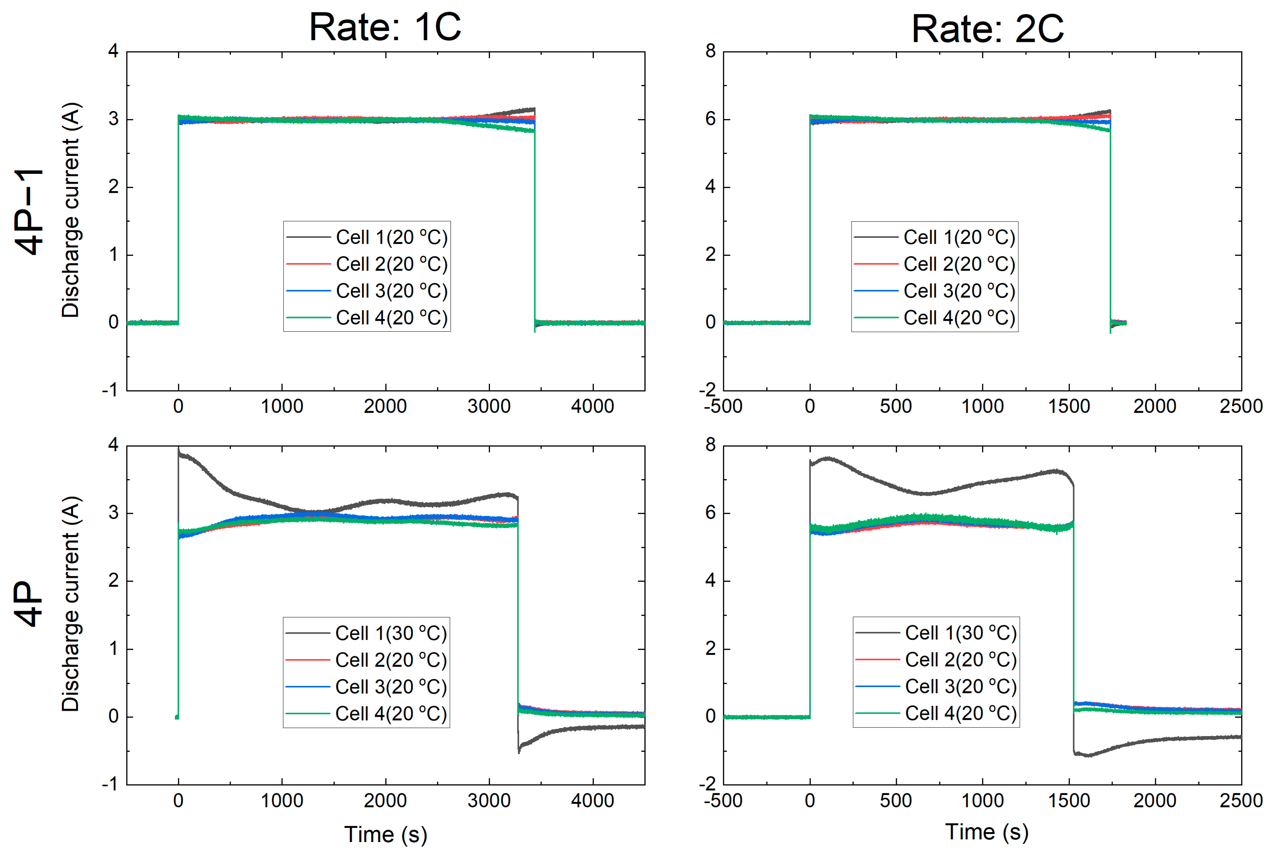
Figure 4 shows the current distribution among cells in the parallel configurations at different discharge rates. In the 4P−1 configuration, only a small gradient is observed toward the end of discharge, between 10–0% SoC for all three discharge rates. When the external discharge current is stopped, no balancing between the cells is observed. Resistance of lithium-ion batteries increases dramatically at low SoC [24]. Therefore, the small gradient is likely to occur from a small resistance variation toward the end of the discharge. In this experiment, as expected from parallel connected cells, no distinguishable difference in individual cell voltage is observed.
In configuration 4P, the cell C1 temperature was set to 30 °C, whereas C2, C3 and C4 were maintained at 20 °C using a liquid cooling system. At 1C discharge rate, the modules capacities are 11.47 and 10.93 Ah for 4P−1 and 4P modules respectively. A similar kind of pattern is observed for a discharge rate of 2C. A large current distribution gradient, however, was expected from the beginning of the discharge and was observed (Figure 4). At the beginning of discharge, C1 had 45.8% and 37.5% higher current at 1C and 2C discharge, compared to the average current of C2, C3 and C4. The current distribution gradient decrease first as discharge progresses then increases again. There are two counteracting mechanisms for this behaviour. As C1 discharged with higher current, V O C V drops faster compared to other cells. As the cell voltage during discharge same for all cells in parallel, current in cell C1 drops to compensate for the additional drop-in V O C V ( V C e l l = V O C V I * R c e l l ). In a counter mechanism, when cell C1 temperature raises, its resistance drops compared to other cells and therefore increases the current in C1. This mechanism is more pronounced towards the end of discharge, when the resistance of all cells increases, but the increase rate for C1 will be lower due to increased temperature. Capacity discharged from C1 increases, by 11.6% and 24.3% at 1C and 2C discharge rates, compared to the average capacity of C2, C3 and C4. This led to a balancing current when the external discharge current stopped, C1 charged by C2, C3 and C4.

3.1.3. Current Distribution Behaviour during Pulse Power Test

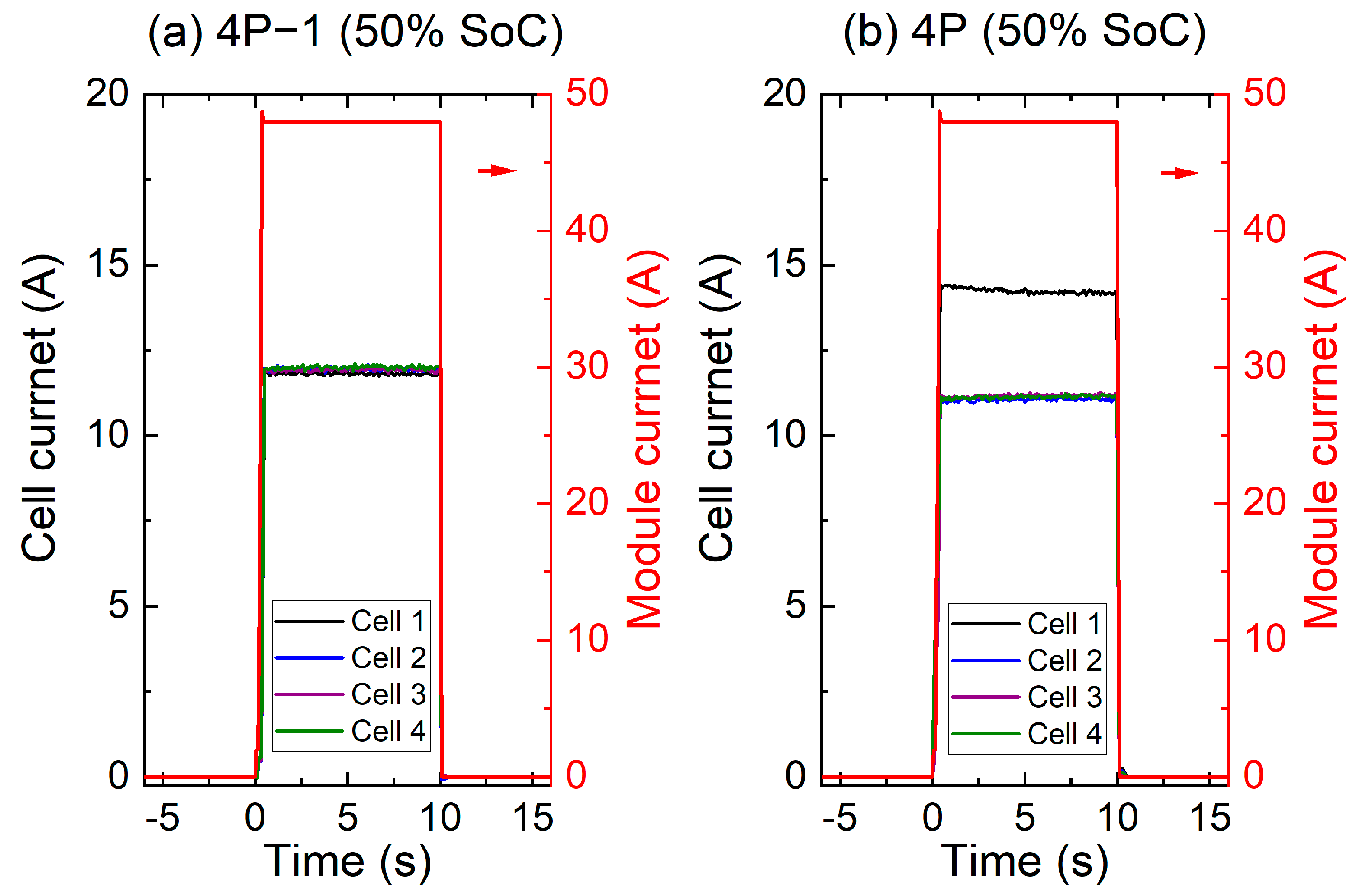
Pulse power test was performed at 80%, 50% and 20% SoC to calculate internal resistances for each configuration. The module resistance was calculated from the voltage and current data recorded by the battery cycler. The resistance of the individual cell was calculated from the module voltage and individual cell current recorded by the current clamp and oscilloscope. Total resistance (Rt) was calculated from the voltage drop at the end of 10 s 4C discharge pulse current [23]. Resistance values are presented in Table 1 and the current distribution during pulse current is presented in Figure 5. The total resistance decreases from 80% SoC to 50% SoC but rises again at 20% SoC, a known feature of lithium-ion cells [24].
There was no distinguishable current distribution gradient across the cells for configuration 4P−1 (Figure 5a). In configuration 4P (Figure 5b), cell C1 takes a larger proportion of current as it was at a higher temperature of 30 °C, therefore lower resistance. These observations follow the current distribution behaviour observed for capacity tests. In the 4P configuration, C2, C3 and C4 should present the same resistance value for a particular SoC as they maintained at 20 °C; which was the case, resistance values for C2, C3 and C4 were within 1% variation at any particular SoC.

3.2. Ageing of Cells and Module

In the following section, the results from the capacity and pulse power test of individual cells and 4P module for a total cumulative 1400 cycles are presented.

3.2.1. Capacity Degradation of Individual Cells and Module

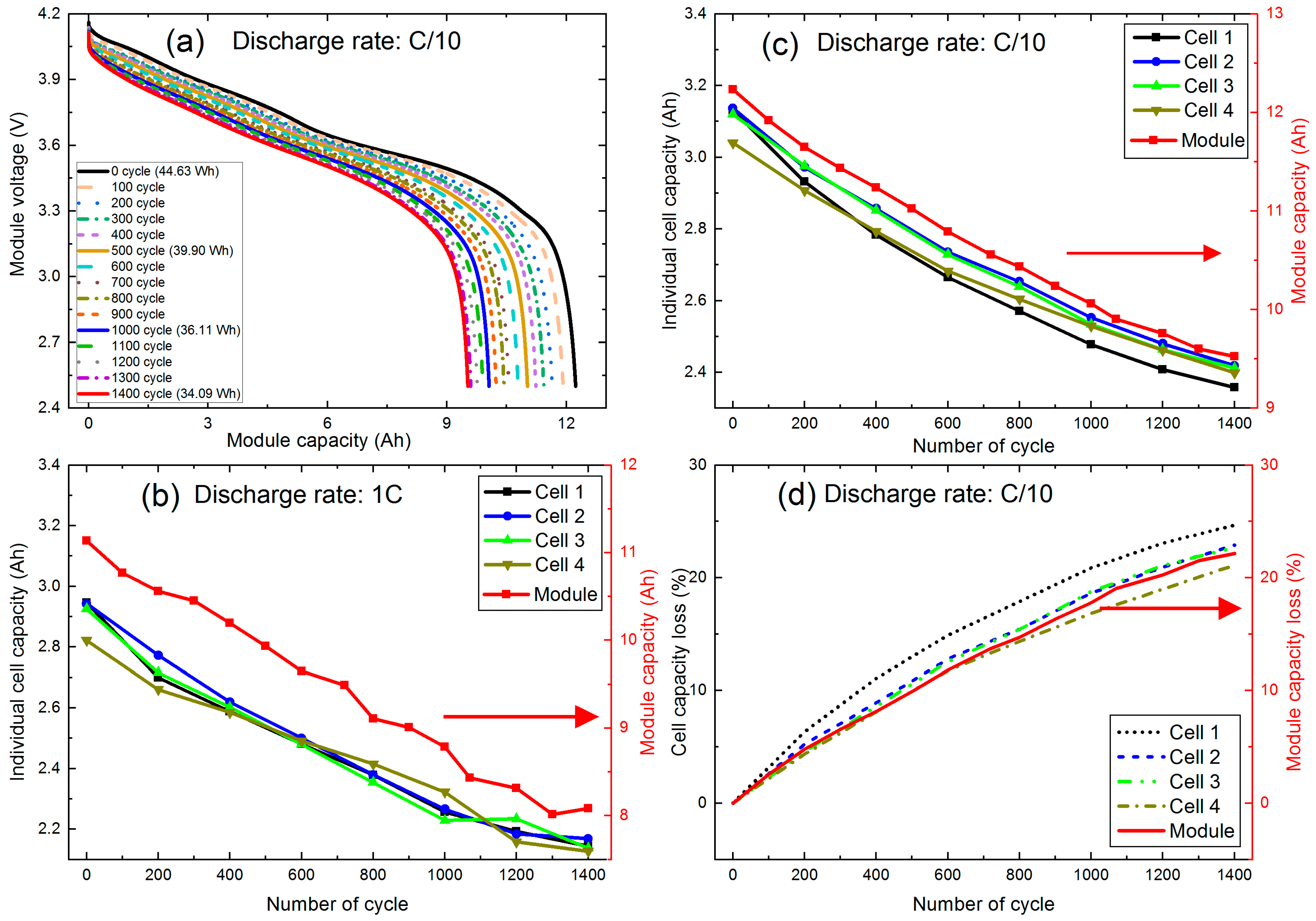
Figure 6a shows the relationship between module capacity and corresponding discharge voltage profile at C/10 after every 100 cycles. The change in capacity varies significantly with voltage and the number of cumulative cycles. Before starting the cycling (0 cycles), the module maximum capacity measured at C/10 is 12.23 Ah (44.63 Wh). After 500 cycles, the module capacity decreases by 9.9% (10.6%) to 11.02 Ah (39.90 Wh); after 1000 and 1400 cycles which further decreases by 17.8% (19.1%) and 22.1% (23.6%) to 10.06 Ah (36.11 Wh) and 9.53 Ah (34.09 Wh) cumulatively. The module capacity measured with 1C discharge was 11.13 Ah at 0 cycles and was degraded by 27% after 1400 cycles. Therefore, 1C capacity test indicates higher degradation than C/10 test after 1400 cycles. This capacity degradation rate is much higher than individual cell level degradation reported (15% after completion of 1200 cycles at 1C rate) in a previous study on a similar cell performed at room temperature 25 °C [25]. The higher degradation rate could be linked to the current distribution and temperature distribution within the connected cells, discussed later in this article.
Figure 6b shows the changes in the capacity of individual cells and a parallel-connected module as a function of ageing cycles at a discharge rate 1C. In the beginning, the cells C1, C2 and C3 have a similar capacity with an average of 2.94 Ah and C4 cell has a lower capacity of 2.82 Ah. After completion of 1400 cycles, the initial capacity of three cells (C1, C2 and C3) reduce by 27% whereas it is slightly lower 25% in C4. The effect of temperature degradation among cells is not distinguishable. This is likely to be an effect of temperature rise in all cells at a higher discharge rate. Figure 6c,d show actual and normalized capacity degradation of individual cells (after every 200 cumulative cycles) and module (after every 100 cumulative cycles) at a discharge rate of C/10. Both the cells and module capacity at C/10 discharge rate are higher than the capacity at 1C rate. At 0 cycles, cells C1, C2 and C3 have a similar capacity 3.13 Ah, and C4 has a slightly lower capacity of 3.04 Ah. The module capacity is 12.23 Ah which is 0.20 Ah lower than that the sum of individual cell capacity. This likely could be due to additional busbar resistance in the 4P configuration. The cell capacity degradation follows a similar trend as the module. However, C1 experiences faster degradation and C4 experiences the slowest degradation. By the end of 1400 cycles, C1 capacity degrades by 24.7%, which for C4 it is 21.1%. This is likely dominated by the fact, C1 is cycled at a higher temperature, which accelerates ageing compared to the other 3 cells. In addition, a higher temperature of C1 reduces its internal resistance, increasing charge-discharge current for this cell compared to the other cells. Also, as cell resistance is lowest, the overpotential is lowest, which might have led to a wider charge/discharge window and higher energy throughput per 100 cycles compared to the other three cells. All these three mechanisms will be discussed later with the current distribution values. Although C4 has the lowest capacity at the beginning of the experiment, at the end of 1400 cycles, it retained a similar capacity as C2 and C3. The lowest degradation rate of C4 might be related to the lowest current amplitude and lower energy throughput compared to C2 and C3, which will be discussed later.

3.2.2. Cell and Module Resistance

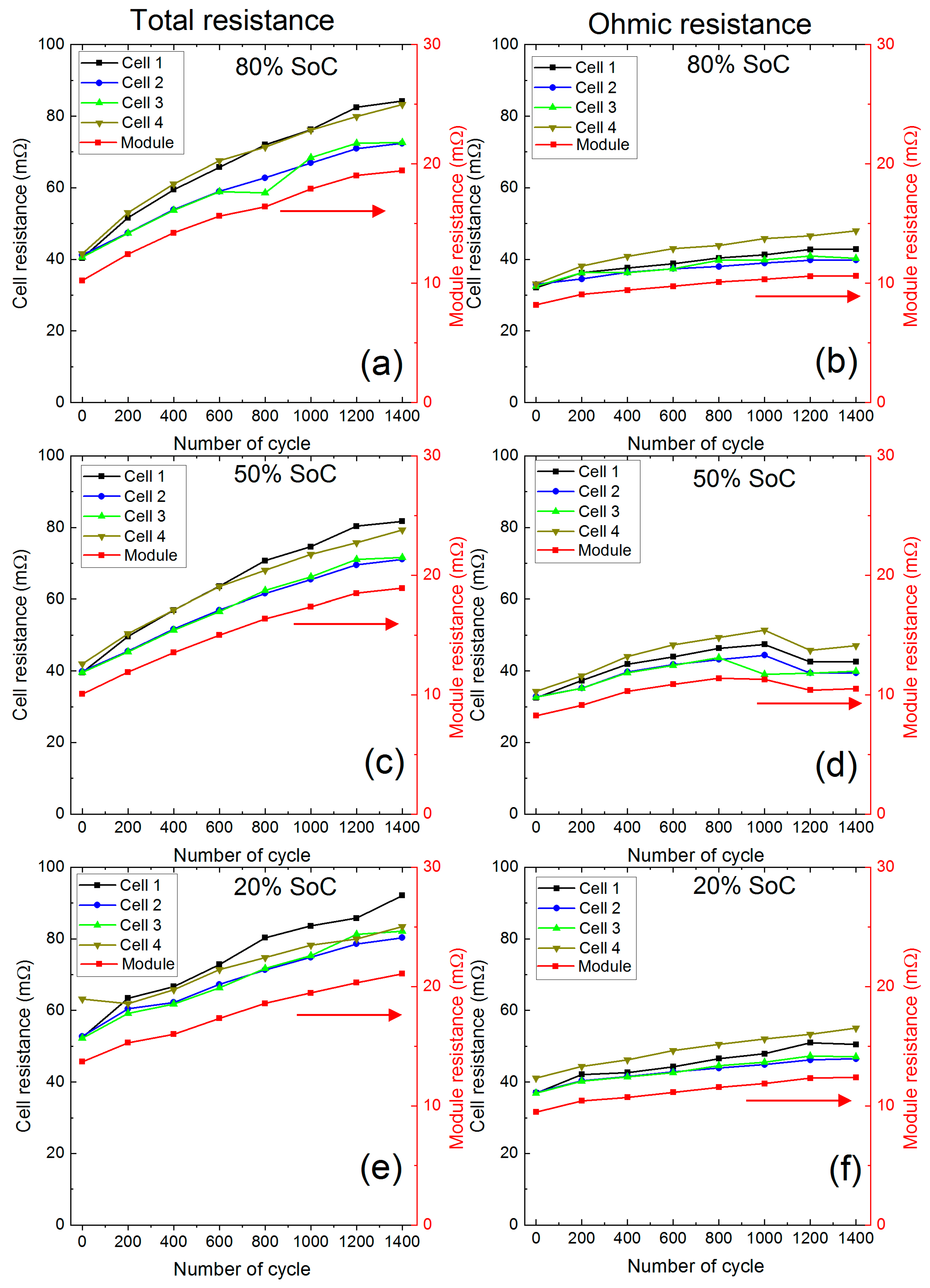
Internal total and ohmic resistance for individual cells and module are plotted as a function of cumulative cycling in Figure 7. Data are shown at SoC 80%, 50% and 20% for 1400 cumulative cycles. All individual cell resistances were measured at 25 °C, whereas module resistance was measure when C1 was at 30 °C and the other three cells at 20 °C. In general, at all three SoC points tested, a steady increase of total and pure ohmic resistance is observed over 1400 cycles.
In the beginning, all four cells have similar total and pure ohmic resistance. At 80% and 50% SoC, cell total resistance raises with the number of cycles. Cells C1 and C4 show higher resistance growth compared to cells C2 and C3. At 80% SoC, C1 experienced the largest total resistance raise in 1400 cycles, i.e., from 40.3 mΩ to 84.2 mΩ, 109%. For C2, C3 and C4, the comparable resistance increase was 76%, 79% and 100%. A similar trend of resistance increase is observed at 50% SoC. At 20% SoC, the resistance raise in C1 is much higher than the other three cells. Although at the beginning of the test, the pure ohmic resistance of the cells is accounted for around 80% of total resistance, it is not the largest source of the resistance growth. Resistance growth is dominated by the dynamic part of the total resistance, indicating a change in the active material. During cycling, C1 was at a higher temperature, therefore experienced higher current amplitude. In contrast, C4 was at the same temperature as C2 and C3 but had the lowest capacity at the beginning of the experiment, which might have an impact on the current amplitude C4 experienced. These might be the leading causes of higher resistance growth in C1 and C4.
The total resistance of the module follows the trend of cell resistance values and increased from 10 mΩ at the beginning of the experiment to 19 mΩ after 1400 cycles at 80% SoC. The module resistance combine resistance for all four cells; however, current distribution during the pulsed current used to measure the module resistance may provide an interesting insight into the degradation and, therefore will be discussed.

3.3. Current and Energy Distribution in Cycling

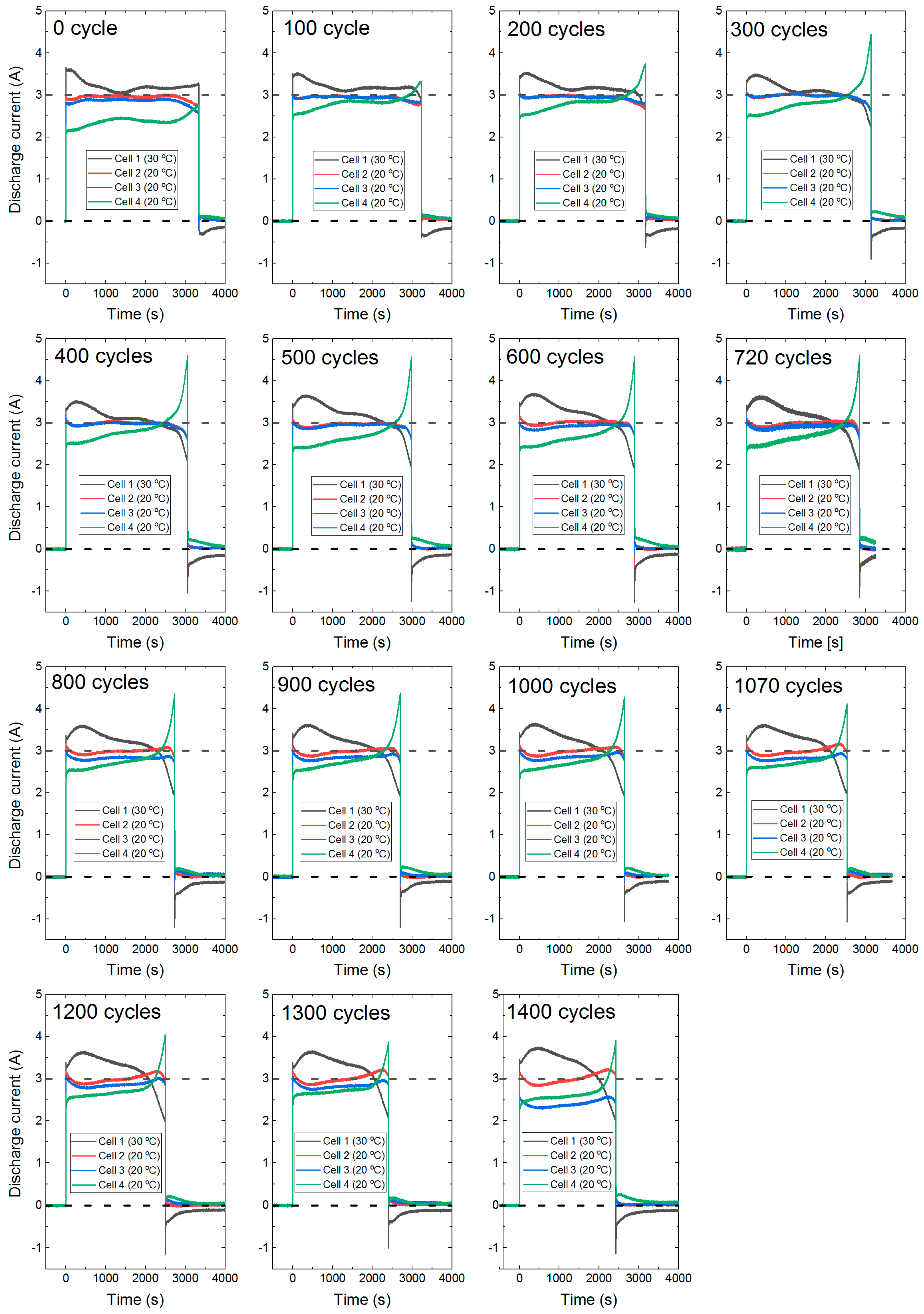
Figure 8 and Figure 9 show the current distribution in cells during cycling and snapshot test in the 4P module at 1C discharge. In all cycling and snapshot cases, at the beginning of the discharge, the C1 current is higher than the other cells and the C4 current is higher at the end of discharge. The average C1 current at the beginning of cycling was around 3.5 A (Figure 8), this average value remained almost steady during cycling until 1400 cycles. Although cell C4 experienced the highest current toward the end of discharge, its average current over the discharge period is the lowest at around 2.6 A, which also remained similar over the experiment duration. Cells C2 and C3 show similar behaviour with an average current of 2.95 A. There are four key features in the current distribution which might have impacted cell degradation, i.e., (1) highest average current in C1 during cycling, (2) high current amplitude in C1 at the beginning of charge/discharge during cycling, (3) highest current amplitude in C4 towards the end of discharge and (4) balancing current at the end of discharge when there was no external current (Figure 9).
(1)
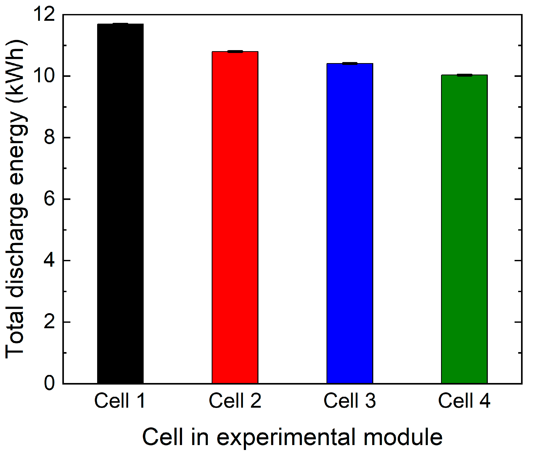
As C1 discharged at a higher average current, it is likely to have gone through higher energy throughput. A comparison in total discharge energy in each cell over the 1400 cycles is shown in Figure 10. Cell C1 had 8.9% higher than average energy throughput. Wang et al. reported a power-law relationship between energy throughput and degradation between 15 °C to 60 °C [26]. With every watt-hour of energy throughput, active lithium will be lost in SEI layer growth and other side reactions often referred to as loss of active lithium (LLI) [1]. This is likely the key source of higher capacity degradation in C1. For the same reason, C4 experiences the lowest capacity degradation, which has 6.5% lower than the average energy throughput.
(2)
Higher charge-discharge current within a lithium-ion battery cell activates different ageing mechanisms such as particle cracking, loss of electrical contact, structural disordering, graphite exfoliation [1]. All these mechanisms will lead to loss of active materials (LAM) and thus internal resistance growth. Cell C1 experiences around 3.5 A discharge current during cycling, which was 0.5 A higher than the average. During charge, C1 also experiences 8.2% higher than the average current over the entire charge duration. While at the beginning of charging, the C1 current is even higher than 70% of the average current, which reduces as the charge progress. The charging protocol of this experiment used the highest charge rate of C/3 for cycling. This led to charging the C1 at a much higher than rated current continuously and for a short period in every charge step. Use of high current, during both charge and discharge, will activate most of the degradation mechanisms related to LAM [1]. This explains higher resistance growth in tandem with higher capacity degradation in cell C1. During charging, 70% higher current than the average value will accelerate lithium plating [27], which accelerates degradation and impose safety risk.
(3)
For cell C4, although the average discharge current was lower, the current increased dramatically towards the last part of the discharge. From 200 cycles onwards, at the end of discharge, the current in C4 was much higher than the cell C1. The maximum end of discharge current in C4 was 4.2 A at the 660th cycle, which decreased to 3.7 A at 1300th cycle. This most likely will activate degradation mechanisms related to LAM [1]. Therefore, C4 experienced higher than average resistance growth, but a lower capacity degradation.
(4)
The change of current amplitude in cells C1 and C4 can provide an interesting insight into the degradation. C1 experienced the highest current amplitude at the first part of the discharge throughout the experiment. From the 100 cycle onwards, the C1 current value initially increased (visible hump in Figure 9) then gradually decreased till the last part of the discharge. The hump increased and become more pronounced as the experiment progressed to 1400 cycles. This is likely to be because of the thermal management of cell C1. During cycling, C1 was at 30 °C within the thermal chamber, whereas C2, C3 and C4 were at 20 °C actively cooled using a liquid cooling system. When discharge started C1 heated up at a higher rate and poorly cooled compared to C2, C3 and C4. This led to further reduction of C1 internal resistance and higher current. However, with reduced resistance the heat generation rate is also reduced, and at a point, this mechanism stabilises, when the peak in C1 current can be observed.
In addition, lithium-ion battery cells internal resistance and voltage is a function of SoC. As discharge progresses, the difference in SoC among the cells increases. SoC of C1 decreases much faster than average and C4′s the slowest. This leads to a reduction of current in C1 and an increase of current in C4 at the middle part of the discharge. As discharge progresses, at the last part of the discharge current in C1 reduces to the lowest and C4 to the highest. This likely indicates a slight over-discharge of C1 and under-discharge of C4. If that is the case, when discharge stopped and there was no external current, there should be a balancing current between cells. This can be observed from the results presented in Figure 9. At the end of every discharge, C1 was charged with around 0.5 A charge current, which was provided by the other three cells, but the highest discharge current was from C4. As the rest period progresses, this balancing current reduces. Therefore, C1 was charged and discharged over a wider window compared to the other three cells, which contributed to both resistance and capacity degradation. This is another source of additional degradation which is not captured in cell-level degradation study but is present in a real-world application.
The result indicates that if there is a gradient in cooling or a temperature gradient within a battery module, parallel-connected cells will degrade differentially. If the temperature gradient persists, it is unlikely that the SoH (state-of-health) of the individual cells in parallel will equalize. The current result also indicates if one cell has lower than average capacity at the beginning of life, its capacity is likely to equalize with degradation as previously reported [5]. However, these results indicate that although their capacity equalizes, a significantly higher resistance growth will occur due to a higher current towards the end of discharge (low SoC). The authors plan a further study with a longer experiment duration, leading to higher degradation covering degradation at the knee point of the cells, which may indicate this difference in resistance may again lead to unequal capacity degradation as the module reaches lower SoH.

4. Conclusions

In this research, the long-term impact of current distribution within parallel connected cells in a module has been investigated. A new experimental methodology and setup design have been presented. The setup allows accurate capture at high resolution, of the current distribution within a real-world representative battery module with parallel-connected cells.
In the ageing test, the results indicate if there is a gradient in cell cooling and thus temperature gradient, a current distribution gradient will be introduced, even when there is minimal cell-to-cell variation. The current gradient will lead to faster capacity and power capability (internal resistance) degradation of poorly cooled cells. When the cells are evenly cooled, the current gradient is minimal among cells with little variation. In an evenly cooled scenario, a cell with slightly lower capacity (likely from cell-to-cell variation) will experience equalization of capacity over a lifetime. However, the result indicates, for such cells, there will be a higher internal resistance growth. The results also indicate during charging that individual cell current can be much higher than the average value, leading to lithium plating, which accelerates degradation further and impose safety risk.
The source of additional capacity degradation is likely SEI growth. The higher internal resistance growth is likely due to structural disordering, particle cracking and loss of electrical contact. The results indicate one of the possible sources of faster degradation of a lithium-ion battery pack in the real world. This also indicates that employing parallel connections to reduce the impact of cell-to-cell variation will not completely remove their long-term impact. Also, this research highlights the requirement of homogeneous thermal management to extend battery life and a detailed investigation of safety implications of higher than intended charge current for an individual cell.

Author Contributions

Conceptualization, A.B. and J.M.; methodology, M.A.-A.; software, T.R.A.; validation, A.B. and J.M.; formal analysis, M.A.-A.; investigation, M.A.-A.; resources, A.B. and J.M.; data curation, M.A.-A.; writing—original draft preparation, M.A.-A. and A.B.; writing—review and editing, A.B. and J.M.; supervision, A.B. and J.M.; project administration, M.A.-A. and A.B.; funding acquisition, A.B. and J.M. All authors have read and agreed to the published version of the manuscript.

Funding

This research was supported by WMG Centre High Value Manufacturing (HVM) Catapult.

Institutional Review Board Statement

Not applicable.

Informed Consent Statement

Not applicable.

Acknowledgments

This research was conducted within the Energy Innovation Centre (EIC) at WMG, the University of Warwick, supported by WMG centre HVM Catapult. We are thankful to the Testing and Characterisation team members for their support with the experiment.

Conflicts of Interest

The authors declare no conflict of interest.

References

  1. Birkl, C.R.; Roberts, M.R.; McTurk, E.; Bruce, P.G.; Howey, D.A. Degradation diagnostics for lithium ion cells. J. Power Sources 2017, 341, 373–386. [Google Scholar] [CrossRef]
  2. Vetter, J.; Novák, P.; Wagner, M.R.; Veit, C.; Möller, K.C.; Besenhard, J.O.; Winter, M.; Wohlfahrt-Mehrens, M.; Vogler, C.; Hammouche, A. Ageing mechanisms in lithium-ion batteries. J. Power Sources 2005, 147, 269–281. [Google Scholar] [CrossRef]
  3. Somerville, L. Post-Mortem Analysis of Lithium-Ion Cells after Accelerated Lifetime Testing. Ph.D. Thesis, University of Warwick, Coventry, UK, 2017. [Google Scholar]
  4. Rothgang, S.; Baumhöfer, T.; van Hoek, H.; Lange, T.; De Doncker, R.W.; Sauer, D.U. Modular battery design for reliable, flexible and multi-technology energy storage systems. Appl. Energy 2015, 137, 931–937. [Google Scholar] [CrossRef]
  5. Bruen, T.; Marco, J. Modelling and experimental evaluation of parallel connected lithium ion cells for an electric vehicle battery system. J. Power Sources 2016, 310, 91–101. [Google Scholar] [CrossRef]
  6. Brand, M.J.; Hofmann, M.H.; Steinhardt, M.; Schuster, S.F.; Jossen, A. Current distribution within parallel-connected battery cells. J. Power Sources 2016, 334, 202–212. [Google Scholar] [CrossRef]
  7. Gogoana, R.; Pinson, M.B.; Bazant, M.Z.; Sarma, S.E. Internal resistance matching for parallel-connected lithium-ion cells and impacts on battery pack cycle life. J. Power Sources 2014, 252, 8–13. [Google Scholar] [CrossRef]
  8. Hosseinzadeh, E.; Marco, J.; Jennings, P. Combined electrical and electrochemical-thermal model of parallel connected large format pouch cells. J. Energy Storage 2019, 22, 194–207. [Google Scholar] [CrossRef]
  9. Hosseinzadeh, E.; Arias, S.; Krishna, M.; Worwood, D.; Barai, A.; Widanalage, D.; Marco, J. Quantifying cell-to-cell variations of a parallel battery module for different pack configurations. Appl. Energy 2021, 282, 115859. [Google Scholar] [CrossRef]
  10. Hofmann, M.H.; Czyrka, K.; Brand, M.J.; Steinhardt, M.; Noel, A.; Spingler, F.B.; Jossen, A. Dynamics of current distribution within battery cells connected in parallel. J. Energy Storage 2018, 20, 120–133. [Google Scholar] [CrossRef]
  11. Fill, A.; Koch, S.; Pott, A.; Birke, K.-P. Current distribution of parallel-connected cells in dependence of cell resistance, capacity and number of parallel cells. J. Power Sources 2018, 407, 147–152. [Google Scholar] [CrossRef]
  12. Luca, R.; Whiteley, M.; Neville, T.; Tranter, T.; Weaving, J.; Marco, J.; Shearing, P.R.; Brett, D.J.L. Current Imbalance in Parallel Battery Strings Measured Using a Hall-Effect Sensor Array. Energy Technol. 2021, 9, 2001014. [Google Scholar] [CrossRef]
  13. Liu, X.; Ai, W.; Naylor Marlow, M.; Patel, Y.; Wu, B. The effect of cell-to-cell variations and thermal gradients on the performance and degradation of lithium-ion battery packs. Appl. Energy 2019, 248, 489–499. [Google Scholar] [CrossRef]
  14. Zhang, Y.; Zheng, J.; Lin, S.; Bai, F.; Tanveer, W.H.; Cha, S.; Wu, X.; Feng, W. Nonuniform current distribution within parallel-connected batteries. Int. J. Energy Res. 2018, 42, 2835–2844. [Google Scholar] [CrossRef]
  15. Grün, T.; Stella, K.; Wollersheim, O. Influence of circuit design on load distribution and performance of parallel-connected Lithium ion cells for photovoltaic home storage systems. J. Energy Storage 2018, 17, 367–382. [Google Scholar] [CrossRef]
  16. Hunt, I.; Zhang, T.; Patel, Y.; Marinescu, M.; Purkayastha, R.; Kovacik, P.; Walus, S.; Swiatek, A.; Offer, G.J. The Effect of Current Inhomogeneity on the Performance and Degradation of Li-S Batteries. J. Electrochem. Soc. 2017, 165, A6073–A6080. [Google Scholar] [CrossRef] [Green Version]
  17. Dubarry, M.; Devie, A.; Liaw, B.Y. Cell-balancing currents in parallel strings of a battery system. J. Power Sources 2016, 321, 36–46. [Google Scholar] [CrossRef] [Green Version]
  18. Gong, X.; Xiong, R.; Mi, C.C. Study of the characteristics of battery packs in electric vehicles with parallel-connected lithium-ion battery cells. IEEE Trans. Ind. Appl. 2015, 51, 1872–1879. [Google Scholar] [CrossRef]
  19. Jocher, P.; Steinhardt, M.; Ludwig, S.; Schindler, M.; Martin, J.; Jossen, A. A novel measurement technique for parallel-connected lithium-ion cells with controllable interconnection resistance. J. Power Sources 2021, 503, 230030. [Google Scholar] [CrossRef]
  20. Christensen, J.; Newman, J. A Mathematical Model of Stress Generation and Fracture in Lithium Manganese Oxide. J. Electrochem. Soc. 2006, 153, A1019–A1030. [Google Scholar] [CrossRef]
  21. Zhou, W.; Hao, F.; Fang, D. The effects of elastic stiffening on the evolution of the stress field within a spherical electrode particle of lithium-ion batteries. Int. J. Appl. Mech. 2013, 5, 1350040. [Google Scholar] [CrossRef]
  22. Sieg, J.; Bandlow, J.; Mitsch, T.; Dragicevic, D.; Materna, T.; Spier, B.; Witzenhausen, H.; Ecker, M.; Sauer, D.U. Fast charging of an electric vehicle lithium-ion battery at the limit of the lithium deposition process. J. Power Sources 2019, 427, 260–270. [Google Scholar] [CrossRef]
  23. Barai, A.; Uddin, K.; Widanage, W.D.; McGordon, A.; Jennings, P. A study of the influence of measurement timescale on internal resistance characterisation methodologies for lithium-ion cells. Sci. Rep. 2018, 8, 21. [Google Scholar] [CrossRef] [PubMed]
  24. Barai, A.; Uddin, K.; Widanalage, W.D.; McGordon, A.; Jennings, P. The effect of average cycling current on total energy of lithium-ion batteries for electric vehicles. J. Power Sources 2016, 303, 81–85. [Google Scholar] [CrossRef]
  25. Uddin, K.; Moore, A.D.; Barai, A.; Marco, J. The effects of high frequency current ripple on electric vehicle battery performance. Appl. Energy 2016, 178, 142–154. [Google Scholar] [CrossRef] [Green Version]
  26. Wang, J.; Liu, P.; Hicks-Garner, J.; Sherman, E.; Soukiazian, S.; Verbrugge, M.; Tataria, H.; Musser, J.; Finamore, P. Cycle-life model for graphite-LiFePO4 cells. J. Power Sources 2011, 196, 3942–3948. [Google Scholar] [CrossRef]
  27. Anseán, D.; Dubarry, M.; Devie, A.; Liaw, B.Y.; García, V.M.; Viera, J.C.; González, M. Operando lithium plating quantification and early detection of a commercial LiFePO 4 cell cycled under dynamic driving schedule. J. Power Sources 2017, 356, 36–46. [Google Scholar] [CrossRef] [Green Version]
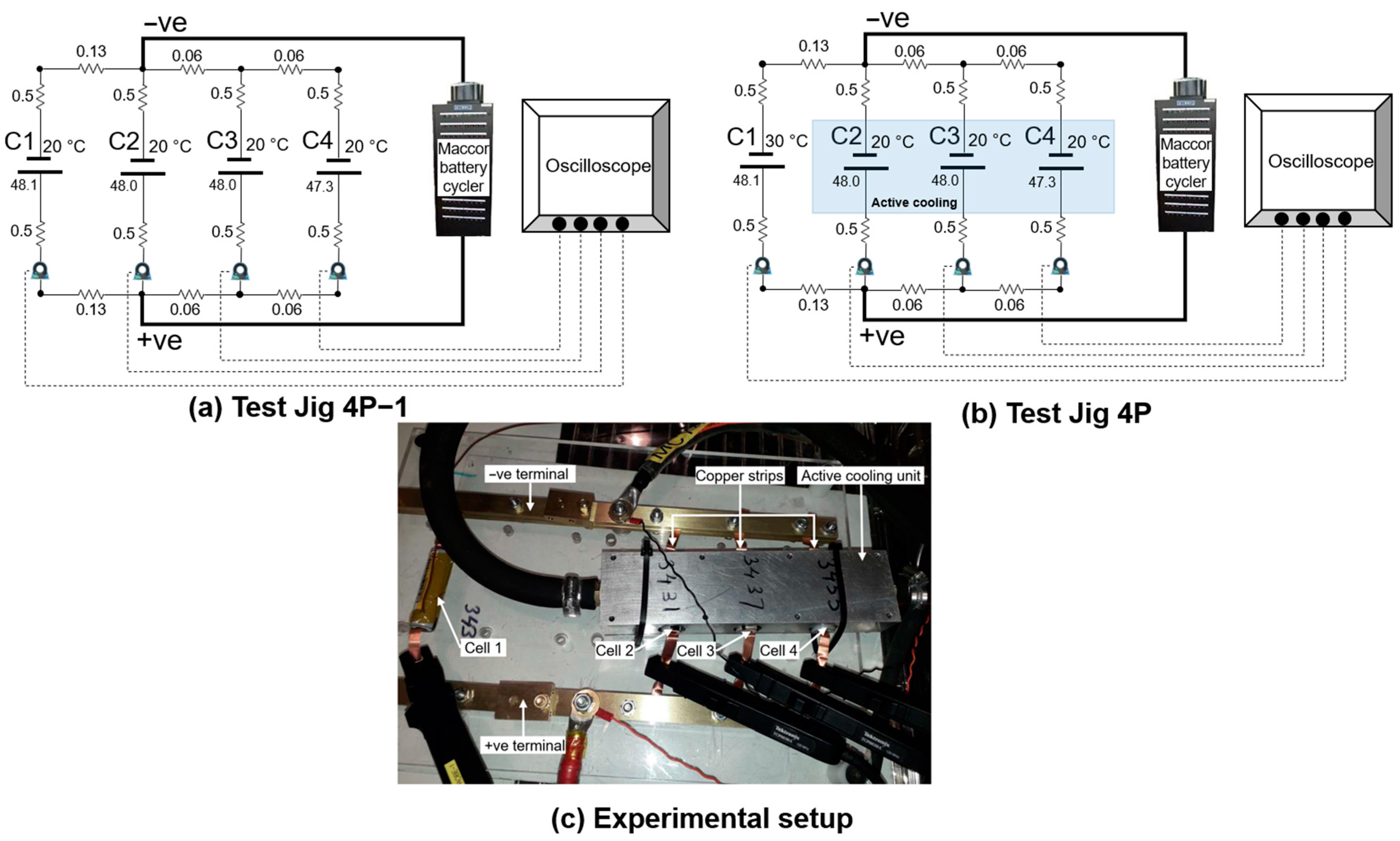
Figure 1. (a) Schematic of four cells in parallel with an air cooling at 20 °C (b) a parallel configuration with a temperature gradient, C1 at 30 °C room temperature and C2, C3 and C4 at 20 °C active cooling (c) real experimental setup of the configuration in (b).
Energies 14 04716 g001
Figure 2. The sequence of snapshot test of individual cells, 4P module and degradation cycles.
Energies 14 04716 g002
Figure 3. Cell voltage versus capacity of individual cells during discharge with rates of C/2, 1C and 2C, measured at room temperature of 20 °C.
Energies 14 04716 g003
Figure 4. Current distribution within the parallel-connected cells during discharge capacity test at 1C and 2C discharge rates for different parallel configurations.
Energies 14 04716 g004
Figure 5. Pulse power test results showing current distribution within the cells at 50% SoC in the parallel connected (a) 4P−1 module with air cooling at 20 °C (b) 4P module with an active liquid cooling (for cells 2, 3 and 4) at 20 °C and cell 1 was maintained at an ambient temperature 30 °C.
Energies 14 04716 g005
Figure 6. Capacity degradation of the module and individual cells, (a) voltage vs. module capacity as a function of ageing cycles, (b) 1C capacity of the module and individual cells, (c) C/10 discharge capacity of the module and individual cells, and (d) normalized C/10 capacity degradation. The module level capacity tests were done at 30 °C in cell C1 and 20 °C in the other three cells. Individual capacity tests were done at 25 °C in all four cells.
Energies 14 04716 g006
Figure 7. Resistance of the individual cells, measured at the three different of SoC (80, 50 and 20%) at 25 °C for cumulative 1400 cycles. The module resistance was calculated based on individual cell resistance. The first column shows the total resistance of individual cells and the 4P module at SoC (a) 80% (c) 50% and (e) 20%. The second column shows the corresponding ohmic resistance at SoC (b) 80% (d) 50% and (f) 20%.
Energies 14 04716 g007
Figure 8. Discharge current distribution in cells in the 4P module cycling for selected cycles. The positive and negative currents represent the discharge and charging state of the module. The numbers represent the cumulative cycling number.
Energies 14 04716 g008
Figure 9. Current distribution in the capacity tests of the module at a discharge rate of 1C after completion of every 100 cycles. The dashed lines represent the rated current of each cell and state before discharging.
Energies 14 04716 g009
Figure 10. The total discharge energy in 1400 cycles for each cell in the parallel-connected module. Cell C1 discharges at 30 °C and other cells at 20 °C. A 0.02% error bar is considered in the analysis.
Energies 14 04716 g010
Table 1. Module and cell resistance values, determined at 80%, 50% and 20% state-of-charge (SoC) in four parallel configurations.
JigSoC %Module Resistance (mΩ)Calculated Module Resistance (mΩ)Cell 1 (mΩ)Cell 2 (mΩ)Cell 3 (mΩ)Cell 4 (mΩ)
4P−18011.511.646.546.246.246.4
4P12.011.939.651.450.851.3
4P−15010.811.045.643.443.443.3
4P11.111.237.548.347.848.0
4P−12014.714.859.058.859.460.2
4P15.015.047.964.464.467.3
Publisher’s Note: MDPI stays neutral with regard to jurisdictional claims in published maps and institutional affiliations.