Abstract
A cubic Bézier-profile plate for multimodal vibration energy harvesting was developed. The design of the plate was based on an optimization procedure in which the profile of the plate was optimized via the parameters of a cubic Bézier curve to meet the requirements. The multimodal energy harvesting of the plate exploited its first bending mode and its first twisting mode. The conversion of vibration energy into electrical energy was by electromagnetic induction with a magnet attached to a corner of the plate. These two closely spaced vibration modes achieved the multi-modal energy harvesting of the device. Prototypes of the device were manufactured using a numerical-control machining process. The experimental results were in good agreement with the design specifications. With the same base lengths, height, and thickness, the maximum von Mises stress of the proposed plate was much lower due to its bell-shaped profile. The cubic Bézier curve chosen for the plate profile was effective for design of the closely-spaced multimodal vibration energy harvester. With the flexibility of its controllable parametric curve, a high design freedom of the energy harvester with specified frequency ratios could be achieved.
1. Introduction
Traditionally, vibration energy harvesting devices are operated at their first resonance frequency for single-frequency ambient energy harvesting [1]. When the ambient vibration is at a single frequency, the design of the energy harvesting device can be tailored to the ambient frequency available. In recent years, a considerable effort was focused on the development of multimodal vibration energy harvesters or power generators due to the multi-frequency content of the vibration energy sources. In order to effectively scavenging vibration energy from the source with multiple vibration modes, design flexibility of the multimodal energy harvester is required. The self-powered sensing/actuating devices located near vibration sources with specific vibration modes further demand robust multimodal energy harvesters.
To account for the frequency variations of the vibration sources, a device with an array of structures with various resonant frequencies can be utilized [2,3,4,5,6]. For miniature energy harvesters applied in microsystems, harvesters made of multiple structures may occupy a large area on device wafers. The other possible route to account for the random ambient vibration sources is to minimize the mechanical damping or maximize the electromechanical coupling of the device [1]. Yang and Lee [7] investigated a nonresonant, electromagnetic wideband energy harvester. The damping effects on the free-standing magnet packaged inside a sealed hole contributed to the wide operation frequency band of their device. Many studies have been focused on incorporating nonlinearities into harvester designs to increase the bandwidth of the devices [6,7,8,9,10,11,12,13,14,15,16]. Nguyen et al. [8] presented a wideband micro-electrostatic energy harvester utilizing a strong softening-spring effect. For increasing levels of random broadband vibration, their harvester displayed a broadening bandwidth response. A bias voltage input as large as 28.4 V was necessary for proper operation of their electrostatic harvester. Andò et al. [9] reported a bistable microdevice for wideband vibration energy harvesting. They found that the nonlinear system exhibited a low-pass filter behaviour suitable for harvesting ambient energy at a low-frequency range. Masana and Daqaq [11] investigated the energy-harvesting performance of a bistable piezoelectric beam in its monostable and bistable configurations. They found that for a bistable beam with shallow potential wells, the activation of interwell dynamics can generate large voltage outputs in the low-frequency range. Using a piezoelectric cantilever with magnet repulsion, Ferrari et al. [12] demonstrated a 400% increase in the output voltage when their harvester operated in the bistable regime compared to the monostable case. Stanton et al. [17] analytically predicted the existence and stability of intrawell and interwell oscillations of a bistable piezoelectric energy generator. They showed that the high-energy orbit of the bistable device existed in a very wide frequency range, especially at lower frequencies. Arrieta et al. [10] investigated a piezoelectric bistable plate generator with seismic masses attached to the corners of the plate. High voltages were obtained for chaos and large amplitude limit-cycle oscillations of their device.
A structure with multiple resonant frequencies may be considered for energy harvesting from random vibrations with multiple resonant peaks; for example, a segmented composite beam with embedded piezoelectric layers [18], V-shaped and open delta-shaped plates with attached magnets [19], trunk-shaped beam structures [20], and zigzag beams [21,22,23]. Karami and Inman [24] proposed a zigzag microstructure that had several resonant frequencies, ranging from 100 Hz to 1000 Hz. Their microscale device could be easily fabricated using microfabrication technology. Arafa [25] proposed a trapezoidal plate with two closely spaced vibration modes in order to harvest energy across a broader bandwidth. Arafa [25] adjusted the length of the free edge of the trapezoidal plate to obtain the desired natural frequency ratios for the given height and the base length. For the frequency ratios close to one, the adjusted length might be much larger than the base length. In that case, an extraordinary stress concentration can occur at the corner of the trapezoidal plate. Ching et al. [26] utilized the resonant modes of a spiral spring with a mass at its center to design a multimodal energy harvester. Liu et al. [27] employed concentric rings to support a proof mass for multimodal vibration energy harvesting. Five vibration modes were adopted to harvest vibration energy with frequencies lower than 1490 Hz. The in-plane stiffness of their device could be relaxed in order to increase the energy output at higher vibration modes. Berdy et al. [28] presented a multimodal energy harvester with distributed inertial masses attached to a meandering beam. A wide bandwidth of their harvester was enabled by close natural frequency spacing. Rezaeisaray et al. [29] suspended a proof mass using two beams in a parallel configuration to construct a vibration energy harvester. The first three resonant modes were employed to harvest ambient vibration in the low-frequency range. Mallick et al. [30] improved the design of Rezaeisaray et al. [29] by using four beams in a square configuration to support a proof mass for multimodal vibration energy harvesting. Mei and Li [31] used two cylindrical shells and proof masses to form a multimodal vibration energy harvester. Due to the large mode numbers in the frequency range below 1 kHz, their double-wall device exhibited a wide bandwidth for vibration energy harvesting. Castagnetti [32] presented a fractal-inspired beam-type structure for multimodal energy harvesting. The fractal structure had three slots curved along its longitudinal axis in a self-similar pattern.
Salmani and Rahimi [33] showed that the voltage output of a beam-type energy harvester can be improved by tapering the beam with an exponential profile. Parametric curves may be used to describe the profiles of plates for vibration energy harvesting applications. In parametric form, each coordinate of a point on a curve is represented as a function of a single parameter [34]. Parametric-curve-based geometry is flexible enough to give a much better control over the profile of plates to achieve the design goals of desired frequency ratios and high vibration amplitudes. It also has high potential to keep the stress in the plate low. Hosseni and Hamedi [35] reported that variation in geometry and configuration of energy harvesting devices could be utilized to increase the output power.
In this investigation, we developed a plate with a cubic Bézier profile for multimodal vibration energy harvesting. The optimal design of the Bézier plate, with its first two vibration modes closely spaced, was sought by using a multiobjective optimization algorithm. Finite element analyses were used to evaluate the frequency response of the plates. Prototypes of the Bézier plates were fabricated by a numerical-control (NC) machining process. A permanent magnet was fixed at a corner of the plate for energy harvesting through electromagnetic induction. Voltage was induced in a stationary coil by the movement of the magnet. The fabricated device was mounted on an electrodynamic shaker and tested. The experimental results were compared with the results of the analyses. The performance of the proposed design was compared with that of a trapezoidal design in terms of the closeness of the first modal frequency to the second modal frequency and the stress in the plate for multimodal energy harvesting.
2. Plate Design
Figure 1 schematically shows a Bézier-profile plate with a permanent magnet attached to one corner of the longer edge of the plate. A stationary coil is also shown in the figure. The vibration energy was converted to electrical energy according to Faraday’s law of induction. The plate was designed to work near its first (bending) mode and its second (twisting) mode. The shorter edge of the plate with a length of was fixed to a vibrating host structure. The length of the longer edge, ; the height, ; and the thickness, of the plate are indicated in the figure. Figure 2a,b show schematics of the bending and twisting modes, respectively. Given the dimensions , , , and of the plate, the desired values of the first two resonant frequencies could be obtained by proper design of the plate profile. The permanent magnet located at one corner of the front edge of the plate had a large displacement when excitation frequencies were near the first and second modal frequencies of the plate. As the plate resonated in response to external vibrations in the designed frequency range, the multimodal power generation by means of electromagnetic induction was achieved. Erturk et al. [36] employed a permanent magnet as a tip mass of their structure to tune the modal frequencies to certain values for energy harvesting in the interested range of frequencies. This magnet-configuration-based effect on the vibration modes is not within the scope of this investigation.
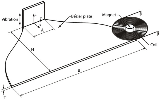
Figure 1.
Schematic of a Bézier plate with a magnet fixed to a corner of the plate’s longer edge. Voltage is generated in the coil according to Faraday’s law of induction.
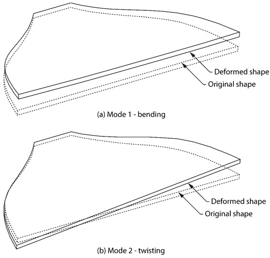
Figure 2.
A schematic of (a) the first vibration mode, and (b) the second vibration mode.
The design of the plate was based on an optimization procedure in which the profile of the plate was optimized via the parameters of a cubic Bézier curve to meet the requirement of the specified closely spaced resonant frequencies of its first two vibration modes. The cubic Bézier curve was determined by a four-point Bézier polygon , as shown in Figure 3. Due to the symmetry of the geometry, only half of the plate is shown in the figure. As described by Rogers and Adams [34], the first and last points, and , respectively, on the curve were coincident with the first and last points of the defining polygon. The tangent vectors at the ends of the curve had the same directions as the first and last polygon spans, respectively. The parametric cubic Bézier curve is given by [34]:
where is the parameter and is the position vector of the point .
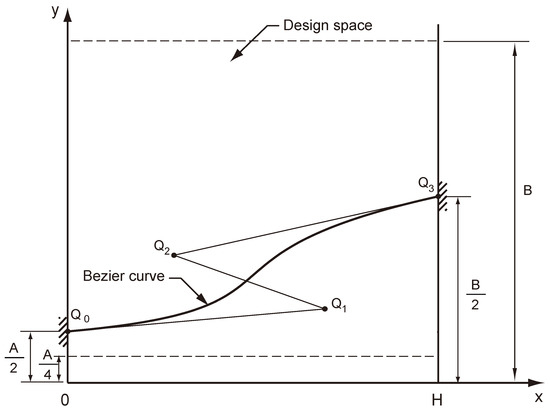
Figure 3.
A profile of a Bézier plate and its four control points (, , , and ).
The profile of the plate was optimized by allowing points and to move in the design space enclosed by the dashed rectangle seen in Figure 3. The positions of the points and were fixed by the specified dimensions of the plate, , , and . The plate was assumed to have a uniform thickness of . An optimization procedure was developed and outlined (Figure 4). The nondominated sorting genetic algorithm [37] was applied to the optimization of the plate profile. The algorithm is suitable for solving constrained multiobjective problems. Given the specified values of , , , and , the design variables were the coordinates of the control points and bounded in the design domain, as shown in Figure 3.
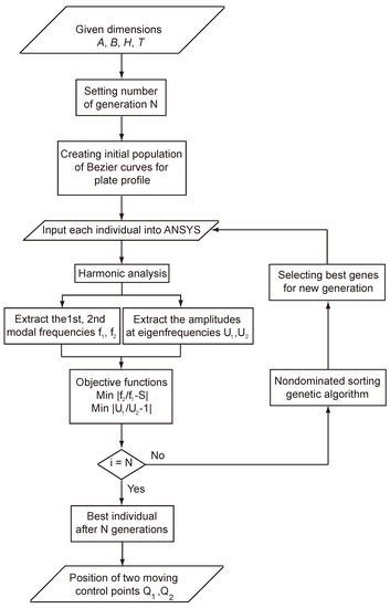
Figure 4.
Flowchart of the optimization procedure.
In the optimization process shown in Figure 4, initially, the geometry parameters , , , and were specified. The objective functions of the optimization problem are:
where and are the first and second modal frequencies of each population in a generation of the plate, respectively, and is defined as the specified ratio of to . and are the vibration amplitudes at the first and second modal frequencies, and , respectively. Due to damping, is generally much greater than . The second objective function, , can increase the amplitude of the second mode for the purpose of multimodal energy harvesting. In this investigation, we focused on the design of the Bézier-profile plate with closely spaced vibration modes. The electrical output of the device was examined in experiments.
Due to the geometric complexity, the modal frequencies, and , and the vibration amplitudes, and , of the Bézier plate were computed numerically. Finite element analysis using the commercial software ANSYS was utilized to obtain modal frequencies and vibration amplitudes of the plate through harmonic analyses. The mode-extraction method, Block Lanczos, was used for the modal analysis to find the geometry parameters of the plate with its resonant frequencies within the interested frequency range [38]. The velocity-proportional Rayleigh damping was considered in the harmonic analyses. The Rayleigh damping matrix has the form:
where and are the mass matrix and stiffness matrix, respectively, and and are constants. The values of and were taken as 3 and 0 , respectively, in the initial design stage of the plate. The genetic algorithm and the optimization procedure were programmed with the MATLAB software. In order to design the plate efficiently, the genetic algorithm, the design parameters (the 4 control points Qi of the Bézier curve), and the geometry constraints were written in a script file in MATLAB. The input file for the ANSYS harmonic analysis to obtain the modal frequencies and the vibration amplitudes was created by the MATLAB file. The output of the ANSYS harmonic simulation was used to evaluate the objective functions for the optimization process.
3. Analyses
3.1. Finite Element Model
Figure 5 shows a typical mesh for a three-dimensional finite element model of a Bézier plate. A Cartesian coordinate system is also shown in the figure. The finite element model had 204 20-node elements. A mesh convergence study was performed to obtain accurate solutions. The displacements in the , , and directions of the nodes on the back edge of the plate, indicated in Figure 5, were constrained. The magnet was modeled as a mass element. The mass element was located at a node on the front edge (the longer base edge) of the plate, as indicated in the figure. The 20-node quadratic element, Solid186, and the structural mass element. Mass21, were used for the plate and the magnet, respectively, in the finite element model. In this investigation, the material of the plate was assumed to be linear elastic. A mild steel (SS 41) was used for the plate material. The Young’s modulus, Poisson’s ratio, and density of the plate were taken as 210 GPa, 0.3, and 7800 kg m−3, respectively. The magnet had a mass of 1.4 g.
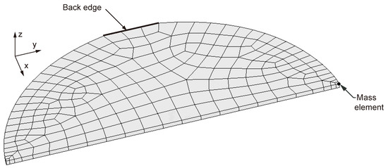
Figure 5.
A typical mesh for a three-dimensional finite element model.
3.2. Numerical Analysis
In the optimization process, the number of generations, N, was set to be 50, and the population of each generation was taken as 100. The height , the base lengths and , and the thickness were specified as 3 cm, 1 cm, 6 cm, and 0.08 cm, respectively. The deformed shapes of the first and second vibration modes of the model for the case of = 1.6 are shown in Figure 6a,b, respectively. The modal frequencies of 310 Hz and 500 Hz, respectively, were responsive when the plate was subjected to external vibrations. Modal analyses of the Bézier plate were carried out to find the first and second modal frequencies in the range of 100–1000 Hz for the low-frequency vibration energy harvesting.
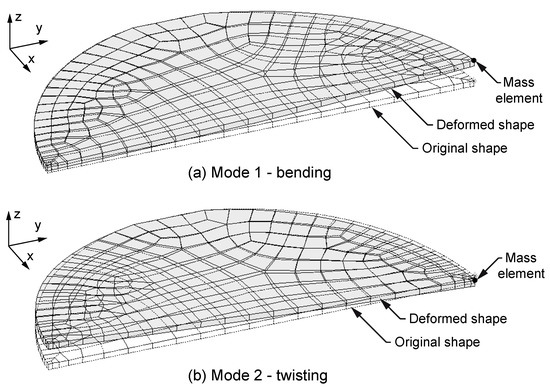
Figure 6.
Deformed shapes of (a) the bending mode and (b) the twisting mode determined by finite element analyses.
Figure 7a,c shows the normalized frequency-response function of the optimized design of the Bézier plate with the specified = 1.6 and 2.0, respectively. The modal frequencies of the first and second modes were 310 Hz and 500 Hz, respectively, for = 1.6; and 264 Hz and 528 Hz, respectively, for = 2.0. The vibration amplitudes were normalized by that of the first mode. The results showed that the plate possessed two resonance frequencies well below 1000 Hz. The ratios of , 9.29 and 9.24, for = 1.6 and 2.0, respectively, were high due to the deliberately selected value of the damping constant of 3 during the design stage of the plate. A lower value of was expected through calibration with experimental results. Figure 7b,d show the profiles of the optimized Bézier plate with the specified = 1.6 and 2.0, respectively. The positions of its control points are also shown in the figure. Table 1 lists the coordinates of the four control points , , , and for the cases considered in this investigation.
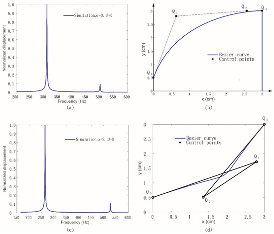
Figure 7.
Normalized frequency response functions for S = 1.6 (a) and S = 2.0 (c); and the profiles of an optimized Bézier plate for S = 1.6 (b) and S = 2.0 (d).

Table 1.
Coordinates of the four control points (, , and ) for various values of the specified .
For plates under external vibration, high stress may occur near the corner of their edges. Stress concentration of a plate may be significantly less than that of the trapezoidal plate reported by Arafa [25] for energy harvesting. The maximum von Mises stresses of the optimized Bézier plate with a frequency ratio of 1.61 were 854 MPa and 120 MPa for mode 1 and mode 2, respectively. The values of these maximum von Mises stresses were much lower than those of the trapezoidal plate (3111 MPa and 562 MPa, respectively). For fair comparison, the trapezoidal plate had the same base lengths, = 1 cm and = 6 cm; thickness, = 0.08 cm; and height, = 3 cm, as those of the Bézier plate. The lower von Mises stress of the Bézier plate could be attributed to its smooth profile. The high stress concentration at the geometric discontinuity of the trapezoidal plate made it prone to failure. Table 2 lists a comparison of the Bézier-profiled plate with the trapezoidal plate. With the same geometric parameters of , , , and , the ratio of the trapezoidal plate was lower than that of the Bézier-profiled plate. The ratio of the proposed design was lower than that of a trapezoidal design with the same geometric parameters. The ratio was a measure of the closeness of the first modal frequency to the second modal frequency. Lower values of the ratio could be achieved by the Bézier plate.
Table 2.
Comparison of the Bézier-profiled plate with the trapezoidal plate.
The proposed Bézier plate was particularly effective in terms of the design flexibility of the frequency ratio for the fixed base lengths, thickness, and height. Figure 8a,c show the normalized frequency response functions of the optimized design of the Bézier plate with a specified frequency ratio of 2.6 and 3.0, respectively. These plates had the same base lengths and , the same thickness , and the same height as those of the Bézier plate with the specified frequency ratio of 1.6 and 2.0. Figure 8b,d show the profiles of the optimized Bézier plate with the specified = 2.6 and 3.0, respectively. For the cases in which the first two modal frequencies were commensurate, a nonlinear energy transfer between these modes could be activated [39]. A broadening in the bandwidth of frequencies containing large-amplitude vibrations could be realized. With the flexibility of the parametric curve, the Bézier plate could be tailored to the desired frequency ratios between the first two vibration modes in the interested frequency range.
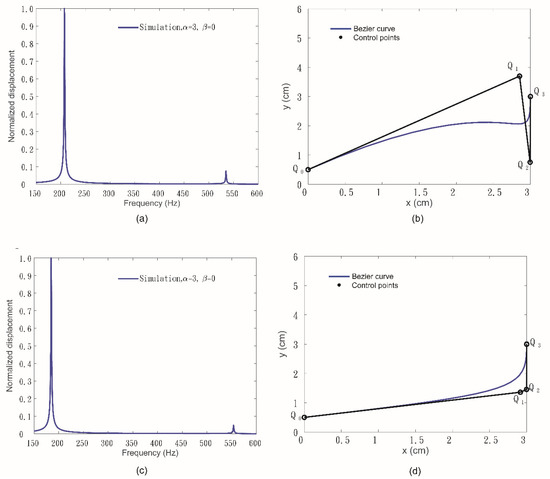
Figure 8.
Normalized frequency response functions for S = 2.6 (a) and S = 3.0 (c); and the profiles of an optimized Bézier plate for S = 2.6 (b) and S = 3.0 (d).
Figure 9 shows the distribution of the population of several generations in the optimization process for the case of . The abscissa represents the objective function . The ordinate represents the objective function . Values of the objective of some populations in the 50th generation were decreased dramatically at the expense of the slightly larger values of the objective . The second modal frequency was equal to , of the best of the population in the 50th generation, and is marked in the figure.
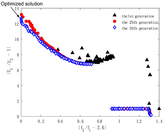
Figure 9.
Distribution of the population of several generations in the optimization process for S = 2.6.
4. Experiments and Discussions
In order to verify the effectiveness of the proposed device, prototypes of the Bézier plate were fabricated by numerical-control machining of a stainless-steel (SS 41) plate. Dimensions of the prototypes were based on the optimized design of the plate with a frequency ratio of 1.61. Figure 10a is a schematic of the experimental apparatus for measurement of the displacement/vibration of the plate when subjected to base excitation provided by an electrodynamic shaker (VS-5V, Vibration Source Technology Co., Ltd., New Taipei City, Taiwan). The plate was mounted on a fixture with screws. A permanent magnet with a mass of 1.4 g, a diameter of 2 mm, and a thickness of 1 mm was attached to a corner of the front edge of the plate. The oscillating displacement of the magnet and the plate was measured by a laser displacement sensor (LK-G5001, KEYENCE Corporation, Osaka, Japan). The LK-H020 laser head was held by a micromanipulator. The measurement was recorded and analyzed with KEYENCE software (LK-Navigator2). Figure 10b shows a photo of the experimental setup. The voltage induced by the coil was recorded and analyzed with a data-acquisition unit (NI-9234, National Instruments Co., Austin, TX, USA). The acceleration of the shaker was measured with an accelerometer (352A24, PCB Piezotronics, Buffalo, NY, USA) glued to the top surface of the shaker. The accelerometer was connected to a sensor signal conditioner (480E09, PCB Piezotronics, Buffalo, NY, USA).
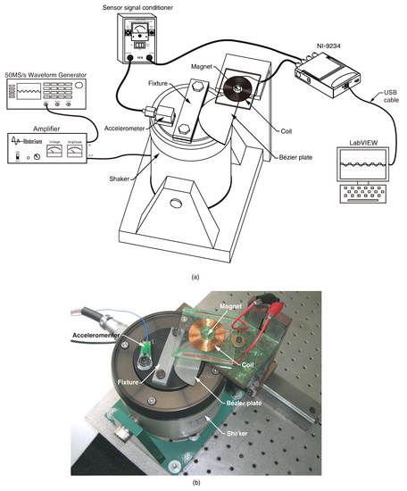
Figure 10.
(a) Schematic; (b) photo of the experimental setup.
Figure 11 shows the measured vibration amplitude of the magnet fixed on the Bézier plate as a function of the excitation frequencies in the range of 100 Hz to 700 Hz. The frequency response of the vibration amplitude based on the finite element analyses with Rayleigh damping is also plotted in Figure 11. The experimental first and second modal frequencies of the plate were 313 Hz and 496 Hz, respectively. The experimental modal frequencies were in a good agreement with those predicted by the analyses, 310 Hz and 500 Hz for mode 1 and mode 2, respectively, with damping of = 3 and = 0. It appeared that the simulated vibration amplitudes at the modal frequencies were much smaller than the experimental results. The value of for the Rayleigh damping was decreased to fit the simulated vibration amplitudes at the modal frequencies of the experiments. The fitted frequency response curve with = 0.5 and = 0 is also shown in the figure. The simulated first and second modal frequencies of the plate were 309 Hz and 500 Hz, respectively, for the case with = 0.5 and = 0. The experimental vibration amplitudes at the first and second modal frequencies were overestimated and underestimated, respectively, by the model with = 0.5 and = 0. The design based on these damping ratios could be conservative to meet the design objective of . Usually, the amplitude of is much larger than that of due to the effects of damping. The error between the modal frequency predictions with and without damping was less than 0.3% for the design cases considered in this investigation.
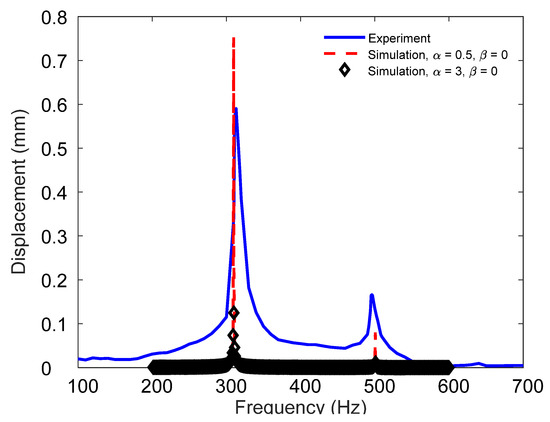
Figure 11.
Experimental frequency response function of the Bézier plate with a frequency ratio of 1.61.
The small discrepancy between the experimental and simulated modal frequencies could be attributed to the manufacturing error and the misalignment of the plate with the fixture in the experimental setup. The experimental frequency ratio of 1.61 was very close to the specified ratio of 1.60. The measured open-circuit voltage induced by the coil is shown in Figure 12. The ordinate represents the output voltage per base acceleration, and the abscissa represents the frequency of the base excitation. The output voltage had peaks at 314 Hz and 494 Hz, which were very close to the first and second modal frequencies, 313 Hz and 496 Hz, respectively, based on the experiments. The experimental results of the voltage output served the purpose to demonstrate the potential of the device for energy harvesting. The model for prediction of the voltage output of the device was not developed. In this investigation, the emphasis was on the design of the plate profiles for closely spaced modal frequencies. Figure 13 shows the frequency-response function of the output power. The two peaks of 251.3 and 6.0 per acceleration occurred at 314 Hz and 494 Hz, respectively. The output power at the second mode was extremely low compared to that of the first mode. This was due to the relatively high frequency ratio of 1.61. For practical applications, higher power output at the second mode can be expected for designs with lower frequency ratios.
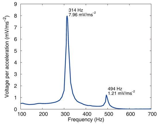
Figure 12.
Output voltage per base acceleration as a function of the excitation frequency.
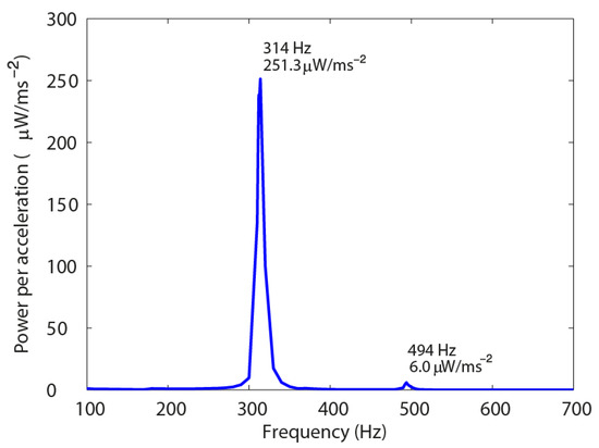
Figure 13.
Output power per base acceleration as a function of the excitation frequency.
With the flexibility of the controllable parametric curve, a cubic Bézier curve, a high design freedom of the energy harvester with specified frequency ratios could be achieved without resorting to blanking out material from the device, as reported by Arafa [25] for a trapezoidal plate. In order to demonstrate the effectiveness of the proposed device for closely spaced modal frequencies, a ratio of = 1.2 was selected for design, with a height = 3 cm, base lengths = 1 cm and = 6 cm, and a thickness = 0.08 cm. The lower and higher boundary of the design space for points and to move were taken as and , respectively, as shown in Figure 3. Rayleigh damping with the damping constants = 0.5 and = 0 was considered in the finite element model during the optimization process. Figure 14a shows the frequency-response function of the optimized solution. The vibration amplitudes were normalized by that of the first mode. Figure 14b shows the profile of the Bézier plate based on the optimized design. The modal frequencies of the first and second modes were 251 Hz and 305 Hz, respectively. The vibration amplitude ratio of was 1.30, based on the optimized solution with . Compared to the frequency-response function for the case with = 1.6, = 0.5 , and = 0 shown in Figure 11, the vibration amplitude ratio, 1.3, in this case was much lower. With a more realistic damping ratio = 0.5 , the effectiveness of the Bézier plate could be assessed by the comparable vibration amplitudes at the first two modal frequencies. This result indicated that the power-output ratio between the first mode and the second mode for the case with the specified = 1.2 could be lower than that with the specified = 1.6. The results indicated that the plate profiled with the cubic Bézier curve may have potential applications in closely spaced multimodal vibration energy harvesting.
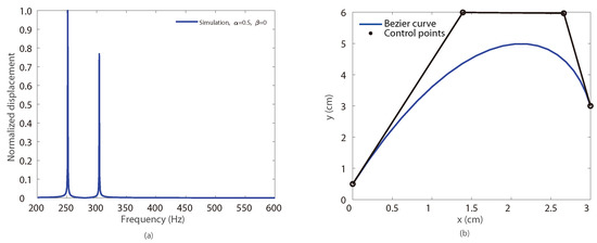
Figure 14.
Normalized frequency response function for S = 1.2 (a), and the profile of an optimized Bézier plate for S = 1.2 (b).
In order to understand the effects of the geometric parameters of the device for the frequency ratio and the vibration amplitude ratio , a parametric study was carried out based on the optimized case, as shown in Figure 14. First, various cases with different lengths of the longer edge were considered. Figure 15 shows the profiles of these cases. Figure 16a shows the values of and as functions of ; and increased as increased for the values of ranging from 2 cm to 10 cm. Figure 16b shows and as functions of the thickness with a profile the same as that of the optimized case in Figure 14b; and decreased as increased from 0.04 cm to 0.14 cm. As the plate with the geometric parameters was perturbed by an optimized solution, a range of solutions with various and values can be found to fulfill the design requirements without resorting to the optimization design procedure if an optimized solution is not required.

Figure 15.
The profiles of Bézier plates with various B values.
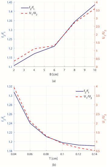
Figure 16.
The frequency ratio and the vibration amplitude ratio as functions of the length of the longer edge (a), and the thickness (b).
For broadband performance of multiresonance harvesters, closely spaced resonant frequencies and a relatively large vibration amplitude in each mode are required [40]. However, the present design exhibited narrow-band harvestable vibration modes. As Xie et al. pointed out in [41], through design optimization, the spectral spacing between these modes can be minimized to provide an effective, multimodal device that operates across a desired frequency band. Frequency ratios and vibration amplitude ratios were used as two design objectives to screen the Bézier plates. This investigation focused on the Bézier-profiled plates with acceptable vibration amplitudes in the first and second modes. The obtained designs can be viewed as near-optimal for the specified frequency ratios and comparable vibration amplitudes. This approach provides design candidates for further screening of all possible configurations of the plates for optimal power output. The present design used electromagnetic-induction means to convert vibration energy into electrical energy. High current and low voltage output are generally expected for an electromagnetic energy harvester. The Bézier-profiled plate can be applied in piezoelectric energy harvesting by attaching piezoelectric strips near the fixed end of the plate to generate high-voltage power output.
5. Conclusions
A plate with a Bézier profile for design of closely spaced multimodal vibration energy harvesting was proposed. The vibration energy was converted to electrical energy through electromagnetic induction. A design procedure using a multiobjective optimization algorithm and finite element analyses was developed to optimize the frequency ratio of the first modal frequency to the second modal frequency of the plate, and the vibration amplitude ratio at the modal frequencies. This procedure could be used to design the plate with different frequency ratios for various dimensional requirements. Prototypes of the device were fabricated and tested to verify the effectiveness of the proposed plate. The experimental results were in good agreement with the design specifications. With the same base lengths, height, and thickness, the maximum von Mises stress of the proposed plate was much lower than that of the trapezoidal plate proposed for energy harvesting. The experimental results showed that the proposed design was particularly effective for closely spaced multimodal energy harvesting. With the flexibility of the parametric curve, the Bézier plate could be designed with two closely spaced vibration modes in the low-frequency range to harvest the ambient vibration energy.
Author Contributions
Conceptualization, D.-A.W.; methodology, D.-A.W.; software, H.-D.N.; validation, H.-D.N. and D.-A.W.; data curation, H.-D.N.; writing—original draft preparation, D.-A.W.; writing—review and editing, D.-A.W.; funding acquisition, D.-A.W. Both authors have read and agreed to the published version of the manuscript.
Funding
This research was funded by the Ministry of Science and Technology, Taiwan, under grant number MOST 100-2221-E-005-078.
Institutional Review Board Statement
Not applicable.
Informed Consent Statement
Not applicable.
Acknowledgments
The authors would like to express their appreciation to the National Center for High-Performance Computing (NCHC), Taiwan, for their assistance.
Conflicts of Interest
The authors declare no conflict of interest. The funders had no role in the design of the study; in the collection, analyses, or interpretation of data; in the writing of the manuscript; or in the decision to publish the results.
References
- Adhikari, S.; Friswell, M.I.; Inman, D.J. Piezoelectric energy harvesting from broadband random vibrations. Smart Mater. Struct. 2009, 18, 115005. [Google Scholar] [CrossRef]
- Liu, J.-Q.; Fang, H.-B.; Xu, Z.-Y.; Mao, X.-H.; Shen, X.-C.; Chen, D.; Liao, H.; Cai, B.-C. A MEMS-based piezoelectric power generator array for vibration energy harvesting. Microelectron. J. 2008, 39, 802–806. [Google Scholar] [CrossRef]
- Ferrari, M.; Ferrari, V.; Guizzetti, M.; Marioli, D.; Taroni, A. Piezoelectric multifrequency energy converter for power harvesting in autonomous microsystems. Sens. Actuators A Phys. 2008, 142, 329–335. [Google Scholar] [CrossRef]
- Castagnetti, D. Experimental modal analysis of fractal-inspired multi-frequency structures for piezoelectric energy converters. Smart Mater. Struct. 2012, 21, 094009. [Google Scholar] [CrossRef]
- Sari, I.; Balkan, T.; Kulah, H. An electromagnetic micro power generator for wideband environmental vibrations. Sens. Actuators A Phys. 2008, 145-146, 405–413. [Google Scholar] [CrossRef]
- Luo, C.; Xu, H.; Wang, Y.; Li, P.; Hu, J.; Zhang, W. Unsymmetrical, interdigital vibration energy harvester: Bandwidth ad-justment based on mode separation technique. Sens. Actuators A Phys. 2017, 257, 30–37. [Google Scholar] [CrossRef]
- Yang, B.; Lee, C. Non-resonant electromagnetic wideband energy harvesting mechanism for low frequency vibrations. Microsyst. Technol. 2010, 16, 961–966. [Google Scholar] [CrossRef]
- Nguyen, D.S.; Halvorsen, E.; Jensen, G.U.; Vogl, A. Fabrication and characterization of a wideband MEMS energy harvester utilizing nonlinear springs. J. Micromech. Microeng. 2010, 20, 125009. [Google Scholar] [CrossRef]
- Andò, B.; Baglio, S.; Trigona, C.; Dumas, N.; Latorre, L.; Nouet, P. Nonlinear mechanism in MEMS devices for energy har-vesting applications. J. Micromech. Microeng. 2010, 20, 125020. [Google Scholar] [CrossRef]
- Arrieta, A.F.; Hagedorn, P.; Erturk, A.; Inman, D.J. A piezoelectric bistable plate for nonlinear broadband energy harvesting. Appl. Phys. Lett. 2010, 97, 104102. [Google Scholar] [CrossRef]
- Masana, R.; Daqaq, M.F. Relative performance of a vibratory energy harvester in mono- and bi-stable potentials. J. Sound Vib. 2011, 330, 6036–6052. [Google Scholar] [CrossRef]
- Ferrarik, M.; Bau, M.; Guizzetti, M.; Ferrari, V. A single-magnet nonlinear piezoelectric cantilever for enhanced energy har-vesting from random vibrations. Sens. Actuators A Phys. 2011, 172, 287–292. [Google Scholar] [CrossRef]
- Drezet, C.; Kacem, N.; Bouhaddi, N. Design of a nonlinear energy harvester based on high static low dynamic stiffness for low frequency random vibrations. Sens. Actuators A Phys. 2018, 283, 54–64. [Google Scholar] [CrossRef]
- Wang, L.; Ding, J.; Jiang, Z.; Luo, G.; Zhao, L.; Lu, D.; Yang, X.; Ryutaro, M. A packaged piezoelectric vibration energy har-vester with high power and broadband characteristics. Sens. Actuators A Phys. 2019, 295, 629–636. [Google Scholar] [CrossRef]
- Huang, Y.; Liu, W.; Yuan, Y.; Zhang, Z. High-energy orbit attainment of a nonlinear beam generator by adjusting the buckling level. Sens. Actuators A Phys. 2020, 312, 112164. [Google Scholar] [CrossRef]
- Jiang, W.; Wang, L.; Zhao, L.; Luo, G.; Yang, P.; Ning, S.; Lu, D.; Lin, Q. Modeling and design of V-shaped piezoelectric vi-bration energy harvester with stopper for low-frequency broadband and shock excitation. Sens. Actuators A Phys. 2021, 317, 112458. [Google Scholar] [CrossRef]
- Stanton, S.C.; Owens, B.A.; Mann, B.P. Harmonic balance analysis of the bistable piezoelectric inertial generator. J. Sound Vib. 2012, 331, 3617–3627. [Google Scholar] [CrossRef]
- Lee, S.; Youn, B.D.; Jung, B.C. Robust segment-type energy harvester and its application to a wireless sensor. Smart Mater. Struct. 2009, 18, 095021. [Google Scholar] [CrossRef]
- El-Hebeary, M.M.; Arafa, M.H.; Megahed, S.M. Modeling and experimental verification of multi-modal vibration energy harvesting from plate structures. Sens. Actuators A Phys. 2013, 193, 35–47. [Google Scholar] [CrossRef]
- Kim, G.-W.; Kim, J.; Kim, J.-H. Flexible piezoelectric vibration energy harvester using a trunk-shaped beam structure inspired by an electric fish fin. Int. J. Precis. Eng. Manuf. 2014, 15, 1967–1971. [Google Scholar] [CrossRef]
- Bai, X.; Wen, Y.; Li, P.; Yang, J.; Peng, X.; Yue, X. Multi-modal vibration energy harvesting utilizing spiral cantilever with magnetic coupling. Sens. Actuators A Phys. 2014, 209, 78–86. [Google Scholar] [CrossRef]
- Ahmad, I.; Khan, F.U. Multi-mode vibration based electromagnetic type micro power generator for structural health moni-toring of bridges. Sens. Actuators A Phys. A 2018, 275, 154–161. [Google Scholar] [CrossRef]
- Mažeika, D.; Čeponis, A.; Vasiljev, P.; Borodinas, S.; Pliuskuvienė, B. Saw-tooth type piezoelectric multi-modal energy har-vester. Sens. Actuators A Phys. 2019, 288, 125–133. [Google Scholar] [CrossRef]
- Karami, M.A.; Inman, D.J. Analytical Modeling and Experimental Verification of the Vibrations of the Zigzag Microstructure for Energy Harvesting. J. Vib. Acoust. 2010, 133, 011002. [Google Scholar] [CrossRef]
- Arafa, M.H. Multi-Modal Vibration Energy Harvesting Using a Trapezoidal Plate. J. Vib. Acoust. 2012, 134, 041010. [Google Scholar] [CrossRef]
- Ching, N.N.H.; Wong, H.Y.; Li, W.J.; Leong, P.H.W.; Wen, Z. A laser-micromachined multi-modal resonating power trans-ducer for wireless sensing systems. Sens. Actuators A Phys. 2002, 97, 685–690. [Google Scholar] [CrossRef]
- Liu, H.; Qian, Y.; Lee, C. A multi-frequency vibration-based MEMS electromagnetic energy harvesting device. Sens. Actuators A Phys. 2013, 204, 37–43. [Google Scholar] [CrossRef]
- Berdy, D.; Jung, B.; Rhoads, J.; Peroulis, D. Wide-bandwidth, meandering vibration energy harvester with distributed circuit board inertial mass. Sens. Actuators A Phys. 2012, 188, 148–157. [Google Scholar] [CrossRef]
- Rezaeisaray, M.; El Gowini, M.; Sameoto, D.; Raboud, D.; Moussa, W. Low frequency piezoelectric energy harvesting at multi vibration mode shapes. Sens. Actuators A Phys. 2015, 228, 104–111. [Google Scholar] [CrossRef]
- Mallick, D.; Constantinou, P.; Podder, P.; Roy, S. Multi-frequency MEMS electromagnetic energy harvesting. Sens. Actuators A Phys. 2017, 264, 247–259. [Google Scholar] [CrossRef]
- Mei, J.; Li, L. Double-wall piezoelectric cylindrical energy harvester. Sens. Actuators A Phys. 2015, 233, 405–413. [Google Scholar] [CrossRef][Green Version]
- Castagnetti, D. Comparison between a wideband fractal-inspired and a traditional multicantilever piezoelectric energy con-verter. J. Vib. Acoust. 2015, 137, 011001. [Google Scholar] [CrossRef]
- Salmani, H.; Rahimi, G.H. Study the effect of tapering on the nonlinear behavior of an exponentially varying width piezoe-lectric energy harvester. J. Vib. Acoust. 2018, 140, 061004. [Google Scholar] [CrossRef]
- Rogers, D.F.; Adams, J.A. Mathematical Elements for Computer Graphics, 2nd ed.; McGRAW-Hill: New York, NY, USA, 1990. [Google Scholar]
- Hosseini, R.; Hamedi, M. Improvements in energy harvesting capabilities by using different shapes of piezoelectric bimorphs. J. Micromech. Microeng. 2015, 25, 125008. [Google Scholar] [CrossRef]
- Erturk, A.; Tarazaga, P.; Farmer, J.R.; Inman, D.J. Effect of Strain Nodes and Electrode Configuration on Piezoelectric Energy Harvesting from Cantilevered Beams. J. Vib. Acoust. 2009, 131, 011010. [Google Scholar] [CrossRef]
- Deb, K.; Pratap, A.; Agarwal, S.; Meyarivan, T. A fast and elitist multiobjective genetic algorithm: NSGA-II. IEEE Trans. Evol. Comput. 2002, 6, 182–197. [Google Scholar] [CrossRef]
- Tadesse, Y.; Zhang, S.; Priya, S. Multi-modal energy harvesting system: Piezoelectric and electromagnetic. J. Intell. Mater. Syst. Struct. 2009, 20, 625–632. [Google Scholar] [CrossRef]
- Chen, L.-Q.; Jiang, W.-A.; Panyam, M.; Daqaq, M.F. A Broadband Internally Resonant Vibratory Energy Harvester. J. Vib. Acoust. 2016, 138, 061007. [Google Scholar] [CrossRef]
- Xiong, X.; Oyadiji, S.O. Tapered Two-Layer Broadband Vibration Energy Harvesters. J. Vib. Acoust. 2015, 137, 031014. [Google Scholar] [CrossRef]
- Xie, M.; Zhang, Y.; Kraśny, M.J.; Rhead, A.; Bowen, C.; Arafa, M. Energy harvesting from coupled bending-twisting oscillations in carbon-fibre reinforced polymer laminates. Mech. Syst. Signal Process. 2018, 107, 429–438. [Google Scholar] [CrossRef]


Publisher’s Note: MDPI stays neutral with regard to jurisdictional claims in published maps and institutional affiliations. |
© 2021 by the authors. Licensee MDPI, Basel, Switzerland. This article is an open access article distributed under the terms and conditions of the Creative Commons Attribution (CC BY) license (https://creativecommons.org/licenses/by/4.0/).