Article

Cascade Membrane System for Separation of Water and Organics from Liquid By-Products of HTC of the Agricultural Digestate—Evaluation of Performance

by
Agnieszka Urbanowska
1,*,
Małgorzata Kabsch-Korbutowicz
1,
Christian Aragon-Briceño
2,
Mateusz Wnukowski
3,
Artur Pożarlik
2,
Lukasz Niedzwiecki
3,
Marcin Baranowski
3,
Michał Czerep
3,
Przemysław Seruga
4,5,
Halina Pawlak-Kruczek
3,
Eduard Bramer
2 and
Gerrit Brem
2
1
Department of Water and Wastewater Treatment Technology, Faculty of Environmental Engineering, Wroclaw University of Science and Technology, Wybrzeże Wyspiańskiego 27, 50-370 Wrocław, Poland
2
Department of Thermal and Fluid Engineering, University of Twente, Postbus 217, 7500 AE Enschede, The Netherlands
3
Department of Energy Conversion Engineering, Faculty of Mechanical and Power Engineering, Wroclaw University of Science and Technology, Wybrzeże Wyspiańskiego 27, 50-370 Wrocław, Poland
4
Department of Bioprocess Engineering, Wroclaw University of Economics, Komandorska 118/120, 53-345 Wrocław, Poland
5
Zakład Gospodarowania Odpadami GAĆ Sp. z o.o., Gać 90, 55-200 Oława, Poland
*
Author to whom correspondence should be addressed.
Energies 2021, 14(16), 4752; https://doi.org/10.3390/en14164752
Submission received: 13 July 2021 / Revised: 29 July 2021 / Accepted: 2 August 2021 / Published: 5 August 2021
(This article belongs to the Special Issue Modelling and Calculation of Raw Material Industry)

Abstract

:
New regulations aimed at curbing the problem of eutrophication introduce limitations for traditional ways to use the by-product of anaerobic digestion—the digestate. Hydrothermal carbonisation (HTC) can be a viable way to valorise the digestate in an energy-efficient manner and at the same time maximise the synergy in terms of recovery of water, nutrients, followed by more efficient use of the remaining carbon. Additionally, hydrothermal treatment is a feasible way to recirculate recalcitrant process residues. Recirculation to anaerobic digestion enables recovery of a significant part of chemical energy lost in HTC by organics dissolved in the liquid effluent. Recirculating back to the HTC process can enhance nutrient recovery by making process water more acidic. However, such an effect of synergy can be exploited to its full extent only when viable separation techniques are applied to separate organic by-products of HTC and water. The results presented in this study show that using cascade membrane systems (microfiltration (MF) → ultrafiltration (UF) → nanofiltration (NF)), using polymeric membranes, can facilitate such separation. The best results were obtained by conducting sequential treatment of the liquid by-product of HTC in the following membrane sequence: MF 0.2 µm → UF PES 10 → NF NPO30P, which allowed reaching COD removal efficiency of almost 60%.

1. Introduction

Biogas production is a proven way to incorporate, in practice, energy-to-waste strategies using various sources of organic waste [1,2,3,4,5,6]. Typically, a footprint of 8 ha/MW of installed power is required to handle and store typical biogas plants, which introduces high costs [7]. Digestate management could be a feasible way to minimise the footprint. Thermal drying, followed by pelletising, could decrease the volume of the digestate significantly [8]. Nonetheless, it comes at the cost of using valuable energy, e.g., using a part of the produced biogas [8], with open-air drying being the only energy-saving option. At the state-of-the-art biogas plant, a liquid obtained after mechanical dewatering of digestate is stored in lagoons, which can be counted as a significant part of the installation’s footprint. Literature reported organic and nutrient removal process to solve the problem of toxicity with biofilms for more economic nitrogen removal [9]. In wastewater treatment, it is stated that biofilm process is present and has degradation possibilities for biogas effluent treatment and is cited in newer publications regarding ORP control and electricity production combined with wastewater treatment [10]. The parameters such as pH, alkalinity, and inorganic carbon content significantly influence the process [11,12]. Such technologies could be used to tackle the problem of nitrogen removal, using extremophilic conditions, tolerating bacteria [13,14,15]. The liquid, rich in nutrients, is stabilised and can be later used for fertilisation purposes. However, significant limitations to this practice are being introduced by the European Nitrates Directive (91/676/EEC) [16], which aims at curbing the eutrophication problem in the EU [16]. Therefore, relatively large areas are needed for spreading, complicating the logistics of such solutions. Moreover, dewatering effluent’s storage inevitably leads to water loss through evaporation, which nowadays is becoming an increasingly scarce resource in the agriculture sector during climate change [17,18,19,20]. Additionally, digestate still contains significant amounts of recalcitrant organic matter [21], which prompted many investigations regarding increasing its availability for further digestion to produce additional amounts of biogas [22,23,24,25,26]. Furthermore, nowadays higienisation of digestate or removal of ammonia is also considered as important issues [27,28].
Hydrothermal carbonisation (HTC) has been recently pointed out as a possibility regarding synergetic recovery of recalcitrant organic matter and water from digestate [29]. HTC is a thermal valorisation process, typically performed at temperatures typically ranging between 180 and 260 °C [30,31,32], in subcritical water, at elevated pressure, which comes from water vapour pressure as well as from gaseous products of HTC [33,34,35]. The use of HTC can enhance mechanical dewatering, as reported for various wet types of biomass [36,37,38,39]. At the temperatures of HTC, the ionic constant of water is a subject of significant increase, nearly doubling at the upper range, compared to ambient temperatures [40]. At such a temperature range, water behaves as a non-polar solvent [40]. A multitude of reactions coinciding with the output of multiple different products can be considered typical for HTC of different types of biomass [41,42]. These reactions do not represent consecutive steps but instead form parallel networks of different reaction pathways [43]. Hydrolysis usually takes place in relatively low temperatures [44]. Dehydration and decarboxylation are also named as reactions that are significant for the HTC process [44,45].
The number of hydroxyl groups decreases due to dehydration [44,46,47], subsequently causing a lower O/C ratio. Decreased amount of carboxyl and carbonyl groups, due to decarboxylation, also slightly decreases solid products’ O/C ratio [44,46,47]. Intermediates become substrates of polymerisation, condensation and aromatisation [43,47,48], which are also instrumental in an aggregation of carbonaceous microspheres [43]. Microspheres precipitate, thus forming secondary hydrochar [43,49].
A decrease in hydroxyl groups is crucial in making hydrothermally carbonised biomass more hydrophobic [50]. This could effectively lower the equilibrium moisture content of biomass [51] and make physical dewatering easier [44,52], which has the potential of significant energy savings since thermal drying of biomass is an energy-intensive process [53,54,55]. The ability to decrease the O/C ratio is beneficial when valorisation is performed, aiming to improve subsequent pyrolysis [56,57,58,59,60]. Moreover, some studies reported relatively easy pelletising of hydrochars [61]. Studies suggested the application of hydrothermal processing in biorefineries [62], opening novel routes for the production of chemicals, such as HMF [63], fertilisers and soil amendments [64,65,66,67,68]. Additionally, improvement in terms of properties relevant from the point of view of solid fuels could be observed, when hydrochars are compared to raw biomass, prior to HTC treatment [69,70,71,72]. This makes hydrothermal carbonisation a prospective valorisation process for low-quality biomass with relatively high moisture content [73,74,75,76].
Overall, recirculation of the liquid by-products or its subsequent use for maximum energy recovery and increased systemic efficiency offers many opportunities [43]. Several studies report the composition of liquid HTC by-products [77,78,79], with many indicating potential synergies between HTC and anaerobic digestion (AD) [52,80,81] or application of the effluent in microbial fuel cells [82].
However, there is a significant gap, regarding the separation of the organic fraction of liquid HTC by-products from water, in order to maximise the recirculation and, at the same time, maintaining the possibility to keep the optimum solid loading of anaerobic digestion reactor, which could be problematic for AD feedstocks with low solid content. Literature sources suggest positive influence of HTC treatment on subsequent membrane separation, with the possible effect of synergy [83]. Promising results were obtained by the authors of his manuscript on ultrafiltration of the HTC effluent, with a significant reduction of COD in the permeate [84]. This study is a consequent follow-up, and its purpose is further optimisation of membrane separation of organic fraction of HTC effluent, using different configurations of a cascade membrane system.

2. Materials and Methods

The research was conducted for the liquid fraction of the digestate from an agricultural biogas plant located in the Silesia region, Poland. Samples were taken at the outlet of the reactor prior to the mechanical dewatering stage. The digestate was stored in a cooler, at the temperature of 5 °C, before the HTC experiment. Figure 1 shows a diagram of the experimental setup. The autoclave vessel, equipped with an external heating mantle that consisted of band heaters, was filled with 3.8 dm3 of wet digestate, which had a solids content of 10.1%. Radwag MAX2A analyser (Radom, Poland), with a scale resolution of 0.001 g and a maximum sample mass of 50 g, was used to determine the moisture content of the digestate, and dry solids content was obtained by difference. Moisture content test was performed at 105 °C. The sample’s mass was considered to be in equilibrium when the first derivative of the mass (dm/dt) was equal to or smaller than 1 mg/min.
The temperature of the heating mantle was controlled by a PLC. Additionally, the temperature was measured inside of the reactor by a K type thermocouple inserted close to the centre of the reactor. Setpoint temperature of 190 °C was chosen, with PID controller keeping the temperature within ±5 °C, as lower temperatures of the typical HTC temperature range (180 °C and 260 °C) are recommended for digestates of agricultural origins by various literature sources [85,86]. HTC pressure was measured by an analogue gauge, and during the experiment, it was close to the water vapour saturation pressure. The residence time in the reactor was 30 min. Reaching the setpoint temperature, the inside of the reactor triggered the time measurement. After 30 min of the process, the mantle was turned off, and the setup was left for cooling overnight. The colander, with clean cotton cloth, was used for the subsequent separation of the effluent and hydrochar. The cooled material was drained for approximately 20 min to let all of the effluents be drained.
The sample of the liquid by-products of HTC, obtained by draining, was also analysed using a gas chromatograph connected to a mass spectrometer (GC-MS), i.e., chromatograph 7820-A and 5977B MSD spectrometer produced by Agilent Technologies (Santa Clara, CA, USA). In the chromatograph, the Stabilwax-DA column from Restek was used. Helium, with a flow rate of 1.5 cm3/min, was used as a carrier gas. The column’s heating program was set in the following order: achieve 50 °C in 5 min, subsequently heat up with a ramp of 10 °C/min until 200 °C and hold for another 20 min. Compounds were automatically identified using NIST-14 MS library by comparing the mass spectra (a minimum match factor of 80% was taken into account). The MS scanning range was m/z 10–450, with a frequency of 1.7 scans/s. The gain factor and EM Volts were 0.5 and 1348.5, respectively. The temperature of MS source and quadrupole was 230 °C and 150 °C, respectively.
Measurements were performed in triplicates for each sample. The calibration curve was done for four different concentrations of each compound, with each concentration done in triplicates. The uncertainty of quantitative GC-MS analysis was calculated for each compound using the standard deviation of the sample, based on an entire population, using the residual standard deviation as the measure of the fitting quality of the calibration curve. The characteristics of the digestate liquid fraction after HTC from the rural biogas plant are presented in Table 1. The assessment of sequential purification possibility of the liquid fraction of the agricultural digestate after HTC was carried out by combining three stages of membrane separation: microfiltration, ultrafiltration and nanofiltration. Figure 2 depicts the experimental matrix. First, an experiment with single microfiltration (MF) membrane was performed and the sample of the permeate was taken (A—Figure 2). Then four more experiments were performed using different combinations of microfiltration and ultrafiltration (UF) membranes, with samples being taken after ultrafiltration (B, C, D, E—Figure 2). This was followed by eight experiments with different combinations of microfiltration, ultrafiltration and nanofiltration (NF) membranes, with samples being taken at the end of the cascade (F, G, H, I, J, K, L, M—Figure 2).
The separation efficiency was measured by the value of removal rate (R), determined from the equation:
R = ( 1 c p c f ) · 100 %
where: cp—concentration of contaminants in permeate, g/m3, cf—contaminant concentration in the feed, g/m3.
The following types of flat sheet membranes were used in the research:
  • MF membrane with a pore size of 0.2 µm made of polypropylene, 25.4 µm thick and 60% porosity (Hoechst Celgard Corporation),
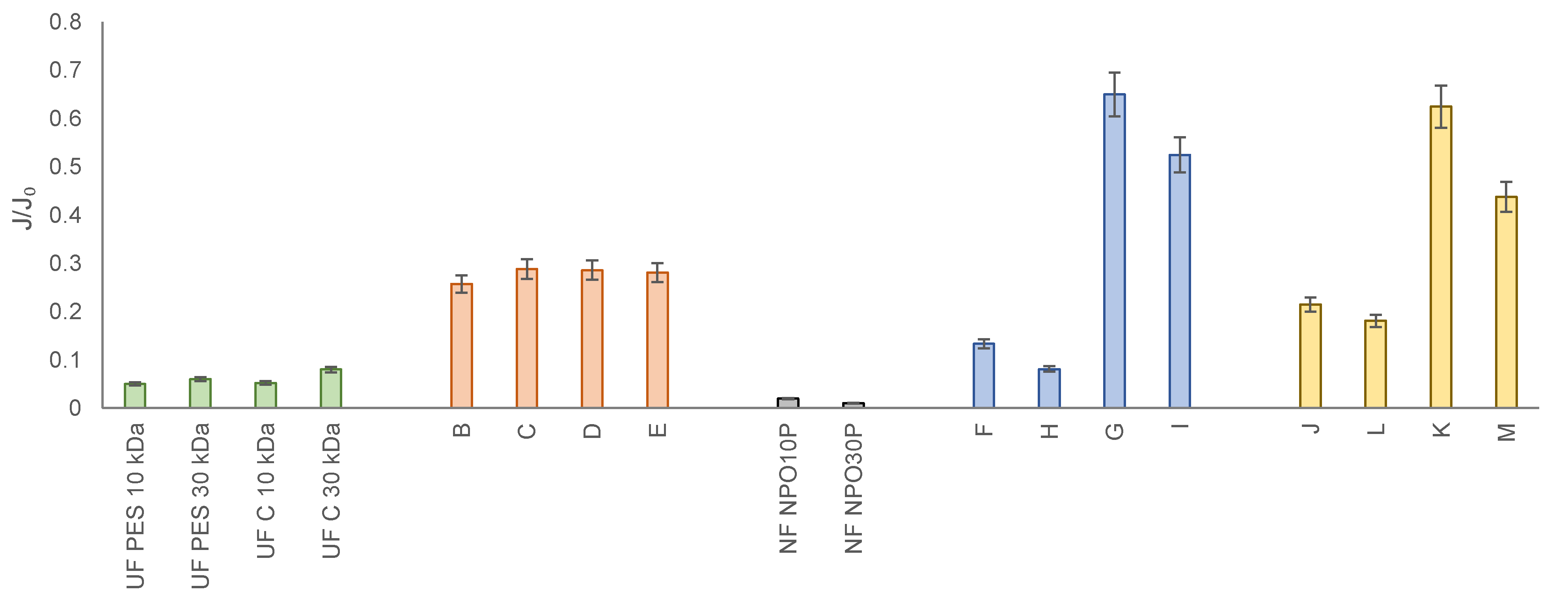
  • Four types of UF membranes (PES 10, PES 30, C 10, C 30) (Microdyn Nadir),
  • Two types of NF membranes (NPO10P and NPO30P) (Microdyn Nadir).
Properties of UF and NF membranes used in the study are presented in Table 2 and Table 3, respectively.
The purification of the liquid fraction of the HTC liquid fraction, after hydrothermal carbonisation of the digestate from the agricultural biogas plant with the use of pressure membrane processes was carried out on a test stand equipped with an Amicon 8400 cell (Millipore, Burlington, MA, USA)—effective filtration surface 45.3 cm2. It allows for a dead-end filtration process and is designed to work with flat membranes. To ensure equal concentration in the entire volume of the solution the filtration cell was placed on a magnetic stirrer. The transmembrane pressure (TMP) in the range of 0.1–0.4 MPa was used in the tests. Nitrogen was used to generate necessary pressure, with limiting error of 0.01 MPa. The following two parameters were used: volume flux of the permeate (J) and organic substances retention coefficient (R) to estimate the separation and transport properties of the membrane under study. The quotient of the permeate flux (J) to the redistilled water flux (J0) was also calculated to determine the relative permeability (J/J0) of the membranes and thus, the membrane fouling susceptibility.
The purification of the liquid fraction of the agricultural digestate was carried out in various variants. The sequential use of the membranes resulted in further analysis:
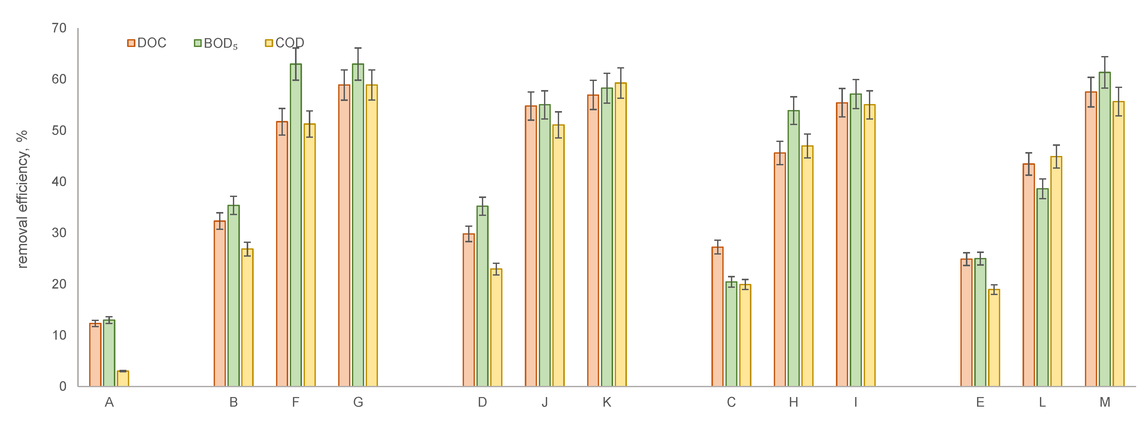
  • A—solution after MF membrane;
  • B—solution after MF followed by UF using a PES 10 kDa membrane;
  • C—solution after MF followed by UF using a PES 30 kDa membrane;
  • D—solution after MF followed by UF using a C 10 kDa membrane;
  • E—solution after MF followed by UF using a C 30 kDa membrane;
  • F—solution after MF followed by UF using a PES 10 kDa membrane and NF using NPO10P membrane;
  • G—solution after MF followed by UF using a PES 10 kDa membrane and NF using NPO30P membrane;
  • H—solution after MF followed by UF using a PES 30 kDa membrane and NF using NPO10P membrane;
  • I—solution after MF followed by UF using a PES 30 kDa membrane and NF using NPO30P membrane;
  • J—solution after MF followed by UF using a C 10 kDa membrane and NF using NPO10P membrane;
  • K—solution after MF followed by UF using a C 10 kDa membrane and NF using NPO30P membrane;
  • L—solution after MF followed by UF using a C 30 kDa membrane and NF using NPO10P membrane;
  • M—solution after MF followed by UF using a C 30 kDa membrane and NF using NPO30P membrane.
The organic compound concentration in the permeates expressed as COD, 5-day BOD (BOD5) and DOC was used to determine the efficiency of the process. Standard methods: dichromate and dilution [89] was used to measure COD and BOD5, respectively. The HACH IL550 TOC-TN analyser (Loveland, CO, USA) was used to measure the DOC concentration.

3. Results and Discussion

Taking into account the fact that the main objective of the research was to separate organic substances present in the digestate liquid fraction after HTC and to recover water from it, which could be used, e.g., in agriculture, special attention was paid to the quality of permeates obtained after successive membrane filtration stages. As an initial step, total organic compounds (DOC) and their biodegradable fraction (BOD5), as well as chemical oxygen demand (COD), were analysed. Subsequently, the content of selected compounds in the permeates was determined using GC-MS analyses. Characteristics of these solutions are presented in Figure 3.
Analysing the effectiveness of the sequential purification of the liquid fraction of the agricultural digestate after HTC, it can be concluded that the final quality of the analysed solution was determined by the combination of separation properties of individual membranes. The combination of microfiltration (MF), ultrafiltration (UF) and nanofiltration (NF) allows for a significant increase in the effectiveness of the purification of the raw solution (liquid fraction of the agricultural digestate after HTC), compared to the effects obtained for independent membrane processes. This effect has been observed for all analysed cases regardless of the membrane cut-off or its material (Figure 4). Overall, it could be stated that proper configuration of the cascade of membranes significantly outperformed single ultrafiltration membrane, investigated in the previous study [84].
The use of microfiltration enables the separation of both colloids and fine suspensions, as well as some macromolecular compounds and microorganisms. For example, at the transmembrane pressure of 0.4 MPa, the obtained values of RDOC, RBOD5 and RCOD were respectively: 12.3%, 13.0% and 3.0%. The redirection of the microfiltration permeate to further purification in the ultrafiltration process showed an increase in the removal efficiency of organic compounds from the analysed digestate due to the combination of sieving mechanisms of both types of analysed membranes. The analysis of the obtained results suggests that the efficiency of digestate purification is generally determined by the cut-off of ultrafiltration membranes. It was observed that with the increase of membrane pore diameter, the efficiency of organic compounds removal decreased. The explanation of this phenomenon is the fact that at a higher membrane cut-off value, larger particles of organic compounds penetrated into the permeate. Moreover, it was noted that the membrane material (polyethersulfone or regenerated cellulose) did not determine the effectiveness of the purification of the tested digestate. For example, a 10 kDa polyethersulfone membrane allowed retention rate for DOC of 32.3%, for BOD5 35.4%, and for COD 26.9% to be achieved, whereas for a regenerated cellulose membrane (10 kDa), reductions in these parameters of 29.8%, 35.2%, and 23%, respectively, were obtained. The use of a 30 kDa membrane resulted in retention values of DOC, BOD5 and COD in purified samples of the digestate of 27.2%, 20.5% and 19.9% and 24.9%, 25.0% and 19.0%, respectively for PES and C membranes (TMP 0.4 MPa).
The application of the nanofiltration in the final stage of the solution purification process resulted in a significant improvement in its quality. This effect has been observed for all tested variants of the use of different types of membranes (both ultrafiltration and nanofiltration). The final quality of the permeate was determined by the combination of properties of sequentially applied membranes. The obtained values of DOC, BOD5 and COD retention coefficients for both tested nanofiltration membranes show how much influence the type of NF membrane used had on the purified solution composition. It was easy to see that using a less compact membrane (NPO10P) resulted in the deterioration of the final permeate quality. For example, the NPO30P membrane allowed to achieve DOC, BOD5 and COD retention coefficients of 58.9%, 63.0% and 58.9%, while the NPO10P membrane allowed to reduce DOC, BOD5 and COD by 51.7%, 63.0% and 51.3% respectively (using a 10 kDa UF PES membrane prior to NF). Better separation properties of the NPO30P membrane could result from its lower cut-off and denser structure [90].
Based on the obtained results, it was found that the best results i.e., the best permeate quality in terms of organic substances content, were achieved by conducting sequential purification in the following variant: microfiltration (0.2 µm) → ultrafiltration (PES 10 membrane) → nanofiltration (NPO30P membrane) (G). Lack of literature sources on membrane separation of organics and water in HTC effluent makes direct comparison difficult. Urbanowska et al. [84] reported COD removal efficiency close to 30% for membrane purification of post HTC effluent, using a single ultrafiltration membrane. Owing to the use of membrane cascades in this study the efficiency was almost doubled (see G in Figure 4 and Figure 5). Klein et al. [91] reported COD removal from effluent with similar organic load i.e., pyrogenic wastewater from oil shale retorting. COD of the samples ranges between 39,700 and 45,400 mg/dm3 [91]. Air stripping resulted in COD removal of more than 30%, whereas ozonation was close to reach COD removal of 50% [91]. Fenton treatment resulted in COD removal ranging between almost 60% and 80%, depending on the COD/H2O2/Fe2+ w/w/w [91]. Only a combination of physical, chemical and biological methods allowed to achieve COD reduction of 98% [91]. However, the advantage of the membrane system is the fact that retentate could still be used as an energy source e.g., for production of biogas [34,81,92], which in turn could be used to produce heat necessary for the HTC process.
It was also advisable to assess the influence of the magnitude of the process driving force (in this case, transmembrane pressure) on the final quality of the effluent after HTC to be treated. It was found (Figure 5) that the transmembrane pressure value has no significant influence on the efficiency of removing organic compounds from the analysed liquid, both in the case of application of single (for MF) and sequentially successive membrane processes. In the analysed range of transmembrane pressures from 0.1 MPa to 0.4 MPa, the DOC, BOD5 and COD retention coefficients were practically at the same level (differences did not exceed 10%).
The purpose of combining membrane processes is, in addition to increasing separation efficiency, to reduce the intensity of membrane fouling. This phenomenon is one of the main problems that occur during the operation of a membrane system, which is caused by the deposit of impurities from the solution to be purified on the membrane surface and in the membrane structure. This results in a decrease in the permeate flux (for processes run at a constant TMP) or an increase in the TMP (for processes run at a constant permeate flux). One method to reduce the intensity of membrane fouling is to purify solutions in integrated systems, such as using sequential membrane processes. As shown in Figure 6, the application of a sequence of the analysed membrane techniques has partially reduced the problem of membrane fouling. Comparison of the J/J0 ratio, obtained in a separate UF process with the MF → UF and separate NF with MF → UF → NF, showed that the use of a pre-filtration improves the transport properties of the last membrane in the process chain. It was found that the application of MF 0.2 µm and UF PES 10 before any of the tested NF membranes reduced the problem of NF membrane fouling. MF applied before UF removes some of the compounds blocking the subsequent membrane, and the use of a more compact UF membrane (10 kDa) made of both PES or C between MF and NF removes the remaining compounds deposited on the surfaces of NF membranes. The use of the 30 kDa cut-off UF membrane, which is characterised by larger pore size and thus lower efficiency of contaminants separation, does not as significantly improve the transport properties of NF membranes, as the fractions remaining in the solution (permeate) may penetrate the pores of the NF membranes or be deposited on its surface further contributing to their blocking. At the same time, it was observed that the type of membrane used in the NF is also crucial in terms of the membrane’s susceptibility to blocking. It was found that after MF 0.2 µm and UF PES 10, the use of the NPO10P membrane resulted in the improvement of transport properties of this membrane. Relative membrane permeability (J/J0) values were larger when using membrane NPO10P at the end of the sequence than when using membrane NPO30P, which may be due, among other things, to the more compact structure of the second membrane. In this case, its fouling is mainly due to the external fouling phenomenon.
Analysing the absolute values of permeate fluxes of nanofiltration membranes, it can be observed that for distilled water, the permeate flux of NPO10P membrane is 1.3272 m3/m2d and for NPO30P membrane: 0.2528 m3/m2d (at TMP 0.4 MPa). When these membranes were used to polish the solution after filtration with a sequence of MF 0.2 µm → UF PES 10 the permeate fluxes of these membranes decrease to 0.79 m3/m2d and 0.158 m3/m2d, respectively. This trend is in line with the literature reports [93]. It can be explained by analysing MWCO values and pore diameters of the membranes tested. According to [90], the cut-off of NPO10P membrane is greater and ranges between 1010 and 1400 Da (with pore diameter 0.80–1.29 nm), while for NPO30P membrane, it equals 500–700 Da (with pore diameter 0.57–0.93 nm). This can result in higher hydraulic resistance and thus lower permeability of NPO30P membranes.
Regarding the possibilities of recirculation of the organic fraction of HTC liquid by-products to AD reactor, the performance of an MF 0.2 µm → UF PES 10 kDa → NF NPO30P (G) cascade was the best among all of the investigated options: overall COD and BOD5 removal efficiencies were close to the highest among all tested combinations (Figure 4). Overall, no trend can be found regarding the concentrations of the compounds found in the HTC effluent before and after different membranes and cascades (Table 4), which could be caused by the complexity of all the interactions between membranes, compounds as well as products of precipitation, produced during HTC.
GC-MS analysis of the raw solution of digestate liquid fraction after HTC samples and after the subsequent membrane filtration stages with different membrane sequences showed that for most low molecular weight organic compounds, the nanofiltration process’s application does not allow for significant elimination of these substances.
The dominant compound in the HTC effluent, namely acetic acid, has not been detected in the permeate when these cascades were used (Table 4), which seems beneficial from the point of view of the use of retentate in the AD since volatile fatty acids are consumed during the acetogenesis [94], which is one of the main stages of AD process [95,96]. From the water-recovery perspective, especially in the context of its potential use in the agriculture, presence of acetic acid could be considered somewhat problematic as it is included on lists of pesticides, e.g., Pesticide Screening List for Luxembourg [97]. The dosage of pesticides is a subject of careful planning in agriculture, so a compound with pesticidal characteristics might be considered problematic when using reclaimed water containing acetic acid for watering the plants. The presence of 2,5-dimethyl pyrazine is also not desirable, as the compound is classified as harmful [98]. If acute toxicity for the compound, ranging between 1020 mg/kg and 1350 mg/kg of body mass (determined by LD50 tests) [99,100], is compared with the concentration presented in Table 4, it seems that significant exposure would be needed to achieve such doses. However, cautiousness is the foundation of present-day health and safety standards. Therefore, it seems sensible to advise an additional stage of treatment after the membrane cascade. Regarding the final concentration of 2,5-dimethyl pyrazine MF 0.2 µm → UF C 30 → NF NPO30P performed slightly better than MF 0.2 µm → UF PES 30 → NF NPO30P (Table 4). The presence of pyrazine is considered a health hazard by ECHA [101]. However, posing a problem of a much smaller magnitude [100]. Ethylpyrazine is a natural product of Maillard reaction [102], used as flavour [102,103], that does not seem problematic, especially in such low concentrations (Table 4).
Propionic acid is merely an irritant with an unpleasant odour [104]. However, concentrations determined within the course of this study were higher than the advised threshold limit value (TLV) of 10 mg/dm3 [104] for all membrane cascades (Table 4). Hydrocinnamic acid presence might not be desired as it is mentioned as an antifungal agent and plant metabolite [105], which cannot be unequivocally stated without further research. The presence of cyclohexanecarboxylic acid poses a severe problem, as the substance is considered a serious health hazard by ECHA [106]. The biggest problem is posed by acetamide’s presence, as the substance is suspected of being carcinogenic to humans [107,108], based on rodent toxicity data and a common potentially genotoxic impurity in pharmaceutical manufacturing [108]. Acetamide is an impurity present in various medicines, and within the jurisdiction of pharmaceutical authorities, it falls under the limit of the threshold of toxicological concern (TTC), which is set as 1.5 μg/day for most known and all suspect carcinogens, unless experimental evidence can justify higher limits [108].
Due to these issues, it should be noted that the cascade membrane system cannot be considered as a stand-alone solution for water recovery from the effluent after HTC of agricultural digestate. Nonetheless, it should not be overlooked that such cascade systems make removal of such compounds significantly easier due to the significant reduction of COD in the permeates. All of the problematic compounds are hydrocarbons and can be oxidised. More research focused on the removal of the most problematic compounds from HTC effluent is advised.

4. Conclusions

In view of the insufficient treatment efficiency of the liquid fraction HTC effluent of the agricultural digestate in the independently used membrane processes, their sequential connections were used. The aim of such a procedure was both to improve the final quality of the treated digestate and to reduce the intensity of membrane fouling. The conducted research showed that the combination of sieving mechanisms of the examined membranes significantly increased the removal efficiency of organic compounds from the analysed HTC effluent. It was found that the final quality of the purified solution was determined by the membrane cut-off value, while the applied TMP and the ultrafiltration membrane material were of no significance. The best results were obtained by conducting sequential treatment of the solution in the following variant: MF 0.2 µm → UF PES 10 → NF NPO30P, which allowed reaching COD removal efficiency of almost 60%. All of the cascades outperformed a single membrane separation performed in the previous study regarding COD removal. Although the applied membrane sequence allows for very significant removal of organic compounds from the solution, there are still considerable amounts of low molecular weight substances remaining in the permeate. Overall, cascade system outperformed single membrane, reported in previous studies. Follow-up studies are advised; studies for further optimization of the cascade systems for separation of water and organics from liquid by-products of HTC of the agricultural digestate, as well as other types of biomass.

Author Contributions

Conceptualisation: A.U. and M.K.-K.; methodology: A.U., M.K.-K., M.W. and C.A.-B.; validation: A.U., M.W. and C.A.-B.; formal analysis: A.U., M.W. and C.A.-B.; investigation: A.U., M.C., M.B. and L.N.; resources: H.P.-K., P.S. and M.K.-K.; data curation: M.C. and M.B.; writing—original draft preparation: A.U., M.K.-K., L.N. and M.W.; writing—review and editing: A.U., M.K.-K., L.N., M.W. and P.S.; visualisation: A.U. and L.N.; supervision: H.P.-K., M.K.-K. and A.P.; project administration: H.P.-K., A.P., E.B. and G.B.; funding acquisition: H.P.-K., M.K.-K., E.B. and G.B. All authors have read and agreed to the published version of the manuscript.

Funding

The authors would like to thank the European Commission, the National Centre for Research and Development (Poland), Nederlandse Organisatie Voor Wetenschappelijk Onderzoek (Netherlands), and Swedish Research Council Formas for funding in the frame of the collaborative international consortium (RECOWATDIG) financed under the 2018 Joint call of the WaterWorks2017 ERA-NET Cofund. This ERA-NET is an integral part of the activities developed by the Water JPI. National Centre for Research and Development agreement number WATERWORKS2017/I/RECOWATDIG/01/2019.

Institutional Review Board Statement

Not applicable.

Informed Consent Statement

Not applicable.

Data Availability Statement

Not applicable.

Acknowledgments

The Authors would also like to thank Joanna Wolska and Katarzyna Smolińska-Kempisty for making microfiltration membranes available for research. The authors would like to thank Butor group for providing the digestate for this research.

Conflicts of Interest

The authors declare no conflict of interest. The funders had no role in the design of the study; in the collection, analyses, or interpretation of data; in the writing of the manuscript, or in the decision to publish the results.

References

  1. Den Boer, J.; Obersteiner, G.; Gollnow, S.; den Boer, E.; Bodnárné Sándor, R. Enhancement of food waste management and its environmental consequences. Energies 2021, 14, 1790. [Google Scholar] [CrossRef]
  2. Den Boer, J.; Kobel, P.; Dyjakon, A.; Urbańska, K.; Obersteiner, G.; Hrad, M.; Schmied, E.; den Boer, E. Food waste in Central Europe—Challenges and solutions. E3S Web Conf. 2017, 22, 00019. [Google Scholar] [CrossRef] [Green Version]
  3. Piechota, G.; Igliński, B. Biomethane in Poland—Current Status, potential, perspective and development. Energies 2021, 14, 1517. [Google Scholar] [CrossRef]
  4. Schmid, C.; Horschig, T.; Pfeiffer, A.; Szarka, N.; Thrän, D. Biogas upgrading: A review of national biomethane strategies and support policies in selected countries. Energies 2019, 12, 3803. [Google Scholar] [CrossRef] [Green Version]
  5. Baltrėnas, P.; Kolodynskij, V.; Zagorskis, A.; Baltrėnaitė, E. Research and analysis of biogas produced from sewage sludge using a batch bioreactor. Environ. Technol. 2018, 39, 3104–3112. [Google Scholar] [CrossRef]
  6. Rasheed, T.; Anwar, M.T.; Ahmad, N.; Sher, F.; Khan, S.U.-D.; Ahmad, A.; Khan, R.; Wazeer, I. Valorisation and emerging perspective of biomass based waste-to-energy technologies and their socio-environmental impact: A review. J. Environ. Manag. 2021, 287, 112257. [Google Scholar] [CrossRef]
  7. Plana, P.V.; Noche, B. A review of the current digestate distribution models: Storage and transport. In Proceedings of the 8 International Conference on Waste Management and The Environment (WM 2016), Valencia, Spain, 7–9 June 2016; Volume 202, pp. 345–357. [Google Scholar]
  8. Monfet, E.; Aubry, G.; Ramirez, A.A. Nutrient removal and recovery from digestate: A review of the technology. Biofuels 2017, 9, 247–262. [Google Scholar] [CrossRef]
  9. Daija, L.; Selberg, A.; Rikmann, E.; Zekker, I.; Tenno, T.; Tenno, T. The influence of lower temperature, influent fluctuations and long retention time on the performance of an upflow mode laboratory-scale septic tank. Desalin. Water Treat. 2016, 57, 18679–18687. [Google Scholar] [CrossRef]
  10. Zekker, I.; Bhowmick, G.D.; Priks, H.; Nath, D.; Rikmann, E.; Jaagura, M.; Tenno, T.; Tämm, K.; Ghangrekar, M.M. ANAMMOX-denitrification biomass in microbial fuel cell to enhance the electricity generation and nitrogen removal efficiency. Biodegradation 2020, 31, 249–264. [Google Scholar] [CrossRef]
  11. Tenno, T.; Uiga, K.; Mashirin, A.; Zekker, I.; Rikmann, E. Modeling closed equilibrium systems of H2O-dissolved CO2-solid CaCO3. J. Phys. Chem. A 2017, 121, 3094–3100. [Google Scholar] [CrossRef]
  12. Tenno, T.; Rikmann, E.; Uiga, K.; Zekker, I.; Mashirin, A.; Tenno, T. A novel proton transfer model of the closed equilibrium system H2O-CO2-CaCO3-NHx. Proc. Est. Acad. Sci. 2018, 67, 260–270. [Google Scholar] [CrossRef]
  13. Zekker, I.; Artemchuk, O.; Rikmann, E.; Ohimai, K.; Dhar Bhowmick, G.; Madhao Ghangrekar, M.; Burlakovs, J.; Tenno, T. Start-Up of Anammox SBR from non-specific inoculum and process acceleration methods by hydrazine. Water 2021, 13, 350. [Google Scholar] [CrossRef]
  14. Zekker, I.; Rikmann, E.; Tenno, T.; Vabamäe, P.; Tomingas, M.; Menert, A.; Loorits, L.; Tenno, T. Anammox bacteria enrichment and phylogenic analysis in moving bed biofilm reactors. Environ. Eng. Sci. 2012, 29, 946–950. [Google Scholar] [CrossRef]
  15. Zekker, I.; Raudkivi, M.; Artemchuk, O.; Rikmann, E.; Priks, H.; Jaagura, M.; Tenno, T. Mainstream-sidestream wastewater switching promotes anammox nitrogen removal rate in organic-rich, low-temperature streams. Environ. Technol. 2020, 42, 3073–3082. [Google Scholar] [CrossRef] [PubMed]
  16. Vázquez-Rowe, I.; Golkowska, K.; Lebuf, V.; Vaneeckhaute, C.; Michels, E.; Meers, E.; Benetto, E.; Koster, D. Environmental assessment of digestate treatment technologies using LCA methodology. Waste Manag. 2015, 43, 442–459. [Google Scholar] [CrossRef] [PubMed]
  17. Xiao, D.; Liu, D.L.; Feng, P.; Wang, B.; Waters, C.; Shen, Y.; Qi, Y.; Bai, H.; Tang, J. Future climate change impacts on grain yield and groundwater use under different cropping systems in the North China Plain. Agric. Water Manag. 2021, 246, 106685. [Google Scholar] [CrossRef]
  18. Aghapour Sabbaghi, M.; Nazari, M.; Araghinejad, S.; Soufizadeh, S. Economic impacts of climate change on water resources and agriculture in Zayandehroud river basin in Iran. Agric. Water Manag. 2020, 241, 106323. [Google Scholar] [CrossRef]
  19. Cortignani, R.; Dell’Unto, D.; Dono, G. Paths of adaptation to climate change in major Italian agricultural areas: Effectiveness and limits in supporting the profitability of farms. Agric. Water Manag. 2021, 244, 106433. [Google Scholar] [CrossRef]
  20. Grusson, Y.; Wesström, I.; Svedberg, E.; Joel, A. Influence of climate change on water partitioning in agricultural watersheds: Examples from Sweden. Agric. Water Manag. 2021, 249, 106766. [Google Scholar] [CrossRef]
  21. Angelidaki, I.; Ahring, B.K. Methods for increasing the biogas potential from the recalcitrant organic matter contained in manure. Water Sci. Technol. 2000, 41, 189–194. [Google Scholar] [CrossRef] [PubMed]
  22. Żubrowska-Sudoł, M.; Podedworna, J.; Bisak, A.; Sytek-Szmeichel, K.; Krawczyk, P.; Garlicka, A. Intensification of anaerobic digestion efficiency with use of mechanical excess sludge disintegration in the context of increased energy production in wastewater treatment plants. E3S Web Conf. 2017, 22, 00208. [Google Scholar] [CrossRef] [Green Version]
  23. Szatyłowicz, E.; Garlicka, A.; Żubrowska-Sudoł, M. The Effectiveness of the organic compounds released due to the hydrodynamic disintegration of sewage sludge. Inżynieria Ekol. 2017, 18, 47–55. [Google Scholar] [CrossRef]
  24. Azman, S.; Milh, H.; Somers, M.H.; Zhang, H.; Huybrechts, I.; Meers, E.; Meesschaert, B.; Dewil, R.; Appels, L. Ultrasound-assisted digestate treatment of manure digestate for increased biogas production in small pilot scale anaerobic digesters. Renew. Energy 2020, 152, 664–673. [Google Scholar] [CrossRef]
  25. Lippert, T.; Bandelin, J.; Xu, Y.; Liu, Y.C.; Robles, G.H.; Drewes, J.E.; Koch, K. From pre-treatment to co-treatment—How successful is ultrasonication of digested sewage sludge in continuously operated anaerobic digesters? Renew. Energy 2020, 166, 56–65. [Google Scholar] [CrossRef]
  26. Villamil, J.A.; Mohedano, A.F.; Rodriguez, J.J.; De la Rubia, M.A. Anaerobic co-digestion of the aqueous phase from hydrothermally treated waste activated sludge with primary sewage sludge. A kinetic study. J. Environ. Manag. 2019, 231, 726–733. [Google Scholar] [CrossRef]
  27. Seruga, P.; Krzywonos, M.; Seruga, A.; Niedzwiecki, L.; Pawlak-Kruczek, H.; Urbanowska, A. Anaerobic digestion performance: Separate collected vs. mechanical segregated organic fractions of municipal solid waste as feedstock. Energies 2020, 13, 3768. [Google Scholar] [CrossRef]
  28. Seruga, P.; Krzywonos, M.; Pyżanowska, J.; Pawlak-Kruczek, H.; Urbanowska, A.; Niedzwiecki, L. Removal of ammonia from the municipal waste treatment effluents using natural minerals. Molecules 2019, 24, 3633. [Google Scholar] [CrossRef] [Green Version]
  29. Pawlak-Kruczek, H.; Urbanowska, A.; Yang, W.; Brem, G.; Magdziarz, A.; Seruga, P.; Niedzwiecki, L.; Pozarlik, A.; Mlonka-Medrala, A.; Kabsch-Korbutowicz, M.; et al. Industrial process description for the recovery of agricultural water from digestate. J. Energy Resour. Technol. 2020, 147, 070917. [Google Scholar] [CrossRef]
  30. Wilk, M.; Magdziarz, A.; Jayaraman, K.; Szymańska-Chargot, M.; Gökalp, I. Hydrothermal carbonization characteristics of sewage sludge and lignocellulosic biomass. A comparative study. Biomass Bioenergy 2019, 120, 166–175. [Google Scholar] [CrossRef]
  31. Magdziarz, A.; Wilk, M.; Wądrzyk, M. Pyrolysis of hydrochar derived from biomass—Experimental investigation. Fuel 2020, 267, 117246. [Google Scholar] [CrossRef]
  32. Smith, A.M.; Ekpo, U.; Ross, A.B. The influence of pH on the combustion properties of bio-coal following hydrothermal treatment of swine manure. Energies 2020, 13, 331. [Google Scholar] [CrossRef] [Green Version]
  33. Sieradzka, M.; Rajca, P.; Zajemska, M.; Mlonka-Mędrala, A.; Magdziarz, A. Prediction of gaseous products from refuse derived fuel pyrolysis using chemical modelling software—Ansys Chemkin-Pro. J. Clean. Prod. 2020, 248, 119277. [Google Scholar] [CrossRef]
  34. Aragón-Briceño, C.I.; Ross, A.B.; Camargo-Valero, M.A. Mass and energy integration study of hydrothermal carbonization with anaerobic digestion of sewage sludge. Renew. Energy 2021, 167, 473–483. [Google Scholar] [CrossRef]
  35. Mihajlović, M.; Petrović, J.; Maletić, S.; Isakovski, M.K.; Stojanović, M.; Lopičić, Z.; Trifunović, S. Hydrothermal carbonization of Miscanthus × giganteus: Structural and fuel properties of hydrochars and organic profile with the ecotoxicological assessment of the liquid phase. Energy Convers. Manag. 2018, 159, 254–263. [Google Scholar] [CrossRef]
  36. Gao, N.; Li, Z.; Quan, C.; Miskolczi, N.; Egedy, A. A new method combining hydrothermal carbonization and mechanical compression in-situ for sewage sludge dewatering: Bench-scale verification. J. Anal. Appl. Pyrolysis 2019, 139, 187–195. [Google Scholar] [CrossRef]
  37. Jackowski, M.; Semba, D.; Trusek, A.; Wnukowski, M.; Niedzwiecki, L.; Baranowski, M.; Krochmalny, K.; Pawlak-Kruczek, H. Hydrothermal carbonization of brewery’s spent grains for the production of solid biofuels. Beverages 2019, 5, 12. [Google Scholar] [CrossRef] [Green Version]
  38. Wang, S.; Persson, H.; Yang, W.; Jönsson, P.G. Pyrolysis study of hydrothermal carbonization-treated digested sewage sludge using a Py-GC/MS and a bench-scale pyrolyzer. Fuel 2020, 262, 116335. [Google Scholar] [CrossRef]
  39. Arauzo, P.; Olszewski, M.; Kruse, A. Hydrothermal carbonization Brewer’s spent grains with the focus on improving the degradation of the feedstock. Energies 2018, 11, 3226. [Google Scholar] [CrossRef] [Green Version]
  40. Reza, M.T.; Yan, W.; Uddin, M.H.; Lynam, J.G.; Hoekman, S.K.; Coronella, C.J.; Vásquez, V.R. Reaction kinetics of hydrothermal carbonization of loblolly pine. Bioresour. Technol. 2013, 139, 161–169. [Google Scholar] [CrossRef]
  41. Román, S.; Libra, J.; Berge, N.; Sabio, E.; Ro, K.; Li, L.; Ledesma, B.; Alvarez, A.; Bae, S. Hydrothermal carbonization: Modeling, final properties design and applications: A review. Energies 2018, 11, 216. [Google Scholar] [CrossRef] [Green Version]
  42. Kruse, A.; Zevaco, T.A. Properties of hydrochar as function of feedstock, reaction conditions and post-treatment. Energies 2018, 11, 674. [Google Scholar] [CrossRef] [Green Version]
  43. Picone, A.; Volpe, M.; Messineo, A. Process water recirculation during hydrothermal carbonization of waste biomass: Current knowledge and challenges. Energies 2021, 14, 2962. [Google Scholar] [CrossRef]
  44. Funke, A.; Ziegler, F. Hydrothermal carbonisation of biomass: A summary and discussion of chemical mechanisms for process engineering. Biofuels Bioprod. Biorefin. 2010, 4, 160–177. [Google Scholar] [CrossRef]
  45. Reza, M.T.; Andert, J.; Wirth, B.; Busch, D.; Pielert, J.; Lynam, J.G.; Mumme, J. Hydrothermal carbonization of biomass for energy and crop production. Appl. Bioenergy 2014, 1, 11–29. [Google Scholar] [CrossRef]
  46. Ameen, M.; Zamri, N.M.; May, S.T.; Azizan, M.T.; Aqsha, A.; Sabzoi, N.; Sher, F. Effect of acid catalysts on hydrothermal carbonization of Malaysian oil palm residues (leaves, fronds, and shells) for hydrochar production. Biomass Convers. Biorefin. 2021, 1–12. [Google Scholar] [CrossRef]
  47. Maniscalco, M.P.; Volpe, M.; Messineo, A. Hydrothermal carbonization as a valuable tool for energy and environmental applications: A review. Energies 2020, 13, 4098. [Google Scholar] [CrossRef]
  48. Pauline, A.L.; Joseph, K. Hydrothermal carbonization of organic wastes to carbonaceous solid fuel—A review of mechanisms and process parameters. Fuel 2020, 279, 118472. [Google Scholar] [CrossRef]
  49. Lucian, M.; Volpe, M.; Gao, L.; Piro, G.; Goldfarb, J.L.; Fiori, L. Impact of hydrothermal carbonization conditions on the formation of hydrochars and secondary chars from the organic fraction of municipal solid waste. Fuel 2018, 233, 257–268. [Google Scholar] [CrossRef]
  50. Shafie, S.A.; Al-attab, K.A.; Zainal, Z.A. Effect of hydrothermal and vapothermal carbonization of wet biomass waste on bound moisture removal and combustion characteristics. Appl. Therm. Eng. 2018, 139, 187–195. [Google Scholar] [CrossRef]
  51. Acharjee, T.C.; Coronella, C.J.; Vasquez, V.R. Effect of thermal pretreatment on equilibrium moisture content of lignocellulosic biomass. Bioresour. Technol. 2011, 102, 4849–4854. [Google Scholar] [CrossRef] [PubMed]
  52. Ahmed, M.; Andreottola, G.; Elagroudy, S.; Negm, M.S.; Fiori, L. Coupling hydrothermal carbonization and anaerobic digestion for sewage digestate management: Influence of hydrothermal treatment time on dewaterability and bio-methane production. J. Environ. Manag. 2021, 281, 111910. [Google Scholar] [CrossRef]
  53. Szufa, S.; Piersa, P.; Adrian, Ł.; Czerwińska, J.; Lewandowski, A.; Lewandowska, W.; Sielski, J.; Dzikuć, M.; Wróbel, M.; Jewiarz, M.; et al. Sustainable drying and torrefaction processes of miscanthus for use as a pelletized solid biofuel and biocarbon-carrier for fertilizers. Molecules 2021, 26, 1014. [Google Scholar] [CrossRef]
  54. Wang, L.; Zhang, L.; Li, A. Hydrothermal treatment coupled with mechanical expression at increased temperature for excess sludge dewatering: Influence of operating conditions and the process energetics. Water Res. 2014, 65, 85–97. [Google Scholar] [CrossRef]
  55. Wang, L.F.; Qian, C.; Jiang, J.K.; Ye, X.D.; Yu, H.Q. Response of extracellular polymeric substances to thermal treatment in sludge dewatering process. Environ. Pollut. 2017, 231, 1388–1392. [Google Scholar] [CrossRef]
  56. Louwes, A.C.; Halfwerk, R.B.; Bramer, E.A.; Brem, G. Experimental study on fast pyrolysis of raw and torrefied woody Biomass. Energy Technol. 2020, 8, 1900799. [Google Scholar] [CrossRef] [Green Version]
  57. Louwes, A.C.; Basile, L.; Yukananto, R.; Bhagwandas, J.C.; Bramer, E.A.; Brem, G. Torrefied biomass as feed for fast pyrolysis: An experimental study and chain analysis. Biomass Bioenergy 2017, 105, 116–126. [Google Scholar] [CrossRef]
  58. Kaczor, Z.; Buliński, Z.; Werle, S. Modelling approaches to waste biomass pyrolysis: A review. Renew. Energy 2020, 159, 427–443. [Google Scholar] [CrossRef]
  59. Sobek, S.; Werle, S. Solar pyrolysis of waste biomass: Part 1 reactor design. Renew. Energy 2019, 143, 1939–1948. [Google Scholar] [CrossRef]
  60. Kantorek, M.; Jesionek, K.; Polesek-Karczewska, S.; Ziółkowski, P.; Stajnke, M.; Badur, J. Thermal utilization of meat-and-bone meal using the rotary kiln pyrolyzer and the fluidized bed boiler—The performance of pilot-scale installation. Renew. Energy 2021, 164, 1447–1456. [Google Scholar] [CrossRef]
  61. Volpe, M.; Wüst, D.; Merzari, F.; Lucian, M.; Andreottola, G.; Kruse, A.; Fiori, L. One stage olive mill waste streams valorisation via hydrothermal carbonisation. Waste Manag. 2018, 80, 224–234. [Google Scholar] [CrossRef]
  62. Procentese, A.; Russo, M.E.; Di Somma, I.; Marzocchella, A. Kinetic characterization of enzymatic hydrolysis of apple pomace as feedstock for a sugar-based biorefinery. Energies 2020, 13, 1051. [Google Scholar] [CrossRef] [Green Version]
  63. Steinbach, D.; Kruse, A.; Sauer, J.; Vetter, P. Sucrose is a promising feedstock for the synthesis of the platform chemical hydroxymethylfurfural. Energies 2018, 11, 645. [Google Scholar] [CrossRef] [Green Version]
  64. Lühmann, T.; Wirth, B. Sewage sludge valorization via hydrothermal carbonization: Optimizing dewaterability and phosphorus release. Energies 2020, 13, 4417. [Google Scholar] [CrossRef]
  65. Meisel, K.; Clemens, A.; Fühner, C.; Breulmann, M.; Majer, S.; Thrän, D. Comparative life cycle assessment of HTC concepts valorizing sewage sludge for energetic and agricultural use. Energies 2019, 12, 786. [Google Scholar] [CrossRef] [Green Version]
  66. Paul, S.; Dutta, A.; Defersha, F. Mechanical and alkaline hydrothermal treated corn residue conversion in to bioenergy and biofertilizer: A resource recovery concept. Energies 2018, 11, 516. [Google Scholar] [CrossRef] [Green Version]
  67. Aragon-Briceño, C.I.; Pozarlik, A.K.; Bramer, E.A.; Niedzwiecki, L.; Pawlak-Kruczek, H.; Brem, G. Hydrothermal carbonization of wet biomass from nitrogen and phosphorus approach: A review. Renew. Energy 2021, 171, 401–415. [Google Scholar] [CrossRef]
  68. Ismail, H.Y.; Shirazian, S.; Skoretska, I.; Mynko, O.; Ghanim, B.; Leahy, J.J.; Walker, G.M.; Kwapinski, W. ANN-Kriging hybrid model for predicting carbon and inorganic phosphorus recovery in hydrothermal carbonization. Waste Manag. 2019, 85, 242–252. [Google Scholar] [CrossRef]
  69. Wilk, M.; Magdziarz, A.; Kalemba-Rec, I.; Szymańska-Chargot, M. Upgrading of green waste into carbon-rich solid biofuel by hydrothermal carbonization: The effect of process parameters on hydrochar derived from acacia. Energy 2020, 202, 117717. [Google Scholar] [CrossRef]
  70. Atallah, E.; Zeaiter, J.; Ahmad, M.N.; Kwapinska, M.; Leahy, J.J.; Kwapinski, W. The effect of temperature, residence time, and water-sludge ratio on hydrothermal carbonization of DAF dairy sludge. J. Environ. Chem. Eng. 2020, 8, 103599. [Google Scholar] [CrossRef]
  71. Atallah, E.; Kwapinski, W.; Ahmad, M.N.; Leahy, J.J.; Zeaiter, J. Effect of water-sludge ratio and reaction time on the hydrothermal carbonization of olive oil mill wastewater treatment: Hydrochar characterization. J. Water Process. Eng. 2019, 31, 100813. [Google Scholar] [CrossRef]
  72. Ghanim, B.M.; Kwapinski, W.; Leahy, J.J. Hydrothermal carbonisation of poultry litter: Effects of initial pH on yields and chemical properties of hydrochars. Bioresour. Technol. 2017, 238, 78–85. [Google Scholar] [CrossRef] [PubMed]
  73. Aragón-Briceño, C.I.; Grasham, O.; Ross, A.B.; Dupont, V.; Camargo-Valero, M.A. Hydrothermal carbonization of sewage digestate at wastewater treatment works: Influence of solid loading on characteristics of hydrochar, process water and plant energetics. Renew. Energy 2020, 157, 959–973. [Google Scholar] [CrossRef]
  74. Śliz, M.; Wilk, M. A comprehensive investigation of hydrothermal carbonization: Energy potential of hydrochar derived from Virginia mallow. Renew. Energy 2020, 156, 942–950. [Google Scholar] [CrossRef]
  75. Surup, G.R.; Leahy, J.J.; Timko, M.T.; Trubetskaya, A. Hydrothermal carbonization of olive wastes to produce renewable, binder-free pellets for use as metallurgical reducing agents. Renew. Energy 2020, 155, 347–357. [Google Scholar] [CrossRef]
  76. Ghanim, B.M.; Pandey, D.S.; Kwapinski, W.; Leahy, J.J. Hydrothermal carbonisation of poultry litter: Effects of treatment temperature and residence time on yields and chemical properties of hydrochars. Bioresour. Technol. 2016, 216, 373–380. [Google Scholar] [CrossRef]
  77. Shrestha, A.; Acharya, B.; Farooque, A.A. Study of hydrochar and process water from hydrothermal carbonization of sea lettuce. Renew. Energy 2021, 163, 589–598. [Google Scholar] [CrossRef]
  78. Atallah, E.; Zeaiter, J.; Ahmad, M.N.; Leahy, J.J.; Kwapinski, W. Hydrothermal carbonization of spent mushroom compost waste compared against torrefaction and pyrolysis. Fuel Process. Technol. 2021, 216, 106795. [Google Scholar] [CrossRef]
  79. Atallah, E.; Kwapinski, W.; Ahmad, M.N.; Leahy, J.J.; Al-Muhtaseb, A.H.; Zeaiter, J. Hydrothermal carbonization of olive mill wastewater: Liquid phase product analysis. J. Environ. Chem. Eng. 2019, 7, 102833. [Google Scholar] [CrossRef]
  80. Parmar, K.R.; Ross, A.B. Integration of hydrothermal carbonisation with anaerobic digestion; Opportunities for valorisation of digestate. Energies 2019, 12, 1586. [Google Scholar] [CrossRef] [Green Version]
  81. Ferrentino, R.; Merzari, F.; Fiori, L.; Andreottola, G. Coupling hydrothermal carbonization with anaerobic digestion for sewage sludge treatment: Influence of HTC liquor and hydrochar on biomethane production. Energies 2020, 13, 6262. [Google Scholar] [CrossRef]
  82. Musa, B.; Arauzo, P.J.; Olszewski, M.P.; Kruse, A. Electricity generation in microbial fuel cell from wet torrefaction wastewater and locally developed corncob electrodes. Fuel Cells 2021, 21, 182–194. [Google Scholar] [CrossRef]
  83. Román, F.; Adolph, J.; Hensel, O. Hydrothermal treatment of biogas digestate as a pretreatment to reduce fouling in membrane filtration. Bioresour. Technol. Rep. 2021, 13, 100638. [Google Scholar] [CrossRef]
  84. Urbanowska, A.; Kabsch-Korbutowicz, M.; Wnukowski, M.; Seruga, P.; Baranowski, M.; Pawlak-Kruczek, H.; Serafin-Tkaczuk, M.; Krochmalny, K.; Niedzwiecki, L. Treatment of liquid by-products of hydrothermal carbonization (HTC) of agricultural digestate using membrane separation. Energies 2020, 13, 262. [Google Scholar] [CrossRef] [Green Version]
  85. Cao, Z.; Hülsemann, B.; Wüst, D.; Illi, L.; Oechsner, H.; Kruse, A. Valorization of maize silage digestate from two-stage anaerobic digestion by hydrothermal carbonization. Energy Convers. Manag. 2020, 222, 113218. [Google Scholar] [CrossRef]
  86. Cao, Z.; Jung, D.; Olszewski, M.P.; Arauzo, P.J.; Kruse, A. Hydrothermal carbonization of biogas digestate: Effect of digestate origin and process conditions. Waste Manag. 2019, 100, 138–150. [Google Scholar] [CrossRef] [PubMed]
  87. MICRODYN-NADIR. Flat Sheet Membrane Data Sheets—MICRODYN-NADIR. Available online: https://www.microdyn-nadir.com/flat-sheet-membrane-data-sheets/ (accessed on 15 February 2021).
  88. Kabsch-Korbutowicz, M. Ultrafiltration as a method of separation of natural organic matter from water. Mater. Sci. Pol. 2008, 26, 459–467. [Google Scholar]
  89. Rice, E.W.; Baird, R.B.; Eaton, A.D. (Eds.) Standard Methods for the Examination of Water and Wastewater, 23rd ed.; American Public Health Association: Washington, DC, USA; American Water Works Association: Denver, CO, USA; Water Environment Federation: Alexandria, VA, USA, 2017. [Google Scholar]
  90. Kovacs, Z.; Samhaber, W. Characterization of nanofiltration membranes with uncharged solutes. Membrantechnika 2008, 12, 22–36. [Google Scholar]
  91. Klein, K.; Kattel, E.; Goi, A.; Kivi, A.; Dulova, N.; Saluste, A.; Zekker, I.; Trapido, M.; Tenno, T. Combined treatment of pyrogenic wastewater from oil shale retorting. Oil Shale 2017, 34, 82–96. [Google Scholar] [CrossRef] [Green Version]
  92. Lucian, M.; Volpe, M.; Merzari, F.; Wüst, D.; Kruse, A.; Andreottola, G.; Fiori, L. Hydrothermal carbonization coupled with anaerobic digestion for the valorization of the organic fraction of municipal solid waste. Bioresour. Technol. 2020, 314, 123734. [Google Scholar] [CrossRef]
  93. Córdova, A.; Astudillo, C.; Giorno, L.; Guerrero, C.; Conidi, C.; Illanes, A.; Cassano, A. Nanofiltration potential for the purification of highly concentrated enzymatically produced oligosaccharides. Food Bioprod. Process. 2016, 98, 50–61. [Google Scholar] [CrossRef]
  94. Reza, M.T.; Werner, M.; Pohl, M.; Mumme, J. Evaluation of Integrated Anaerobic Digestion and Hydrothermal Carbonization for Bioenergy Production. J. Vis. Exp. 2014, 88, e51734. [Google Scholar] [CrossRef] [Green Version]
  95. Kozłowski, K.; Dach, J.; Lewicki, A.; Malińska, K.; Do Carmo, I.E.P.; Czekała, W. Potential of biogas production from animal manure in Poland. Arch. Environ. Prot. 2019, 45, 99–108. [Google Scholar] [CrossRef]
  96. Seruga, P.; Krzywonos, M.; Wilk, M. Thermophilic co-digestion of the organic fraction of municipal solid wastes—The influence of food industry wastes addition on biogas production in full-scale operation. Molecules 2018, 23, 3146. [Google Scholar] [CrossRef] [Green Version]
  97. Krier, J. S69 | LUXPEST | Pesticide Screening List for Luxembourg. Zenodo 2020, 23, 3146. [Google Scholar] [CrossRef]
  98. Substance Information ECHA. 2,5-Dimethylpyrazine. Available online: https://echa.europa.eu/substance-information/-/substanceinfo/100.004.200 (accessed on 19 February 2021).
  99. Moran, E.J.; Easterday, O.D.; Oser, B.L. Acute oral toxicity of selected flavor chemicals. Drug Chem. Toxicol. 1980, 3, 249–258. [Google Scholar] [CrossRef] [PubMed]
  100. Nishie, K.; Waiss, A.C.; Keyl, A.C. Pharmacology of alkyl and hydroxyalkylpyrazines. Toxicol. Appl. Pharmacol. 1970, 17, 244–249. [Google Scholar] [CrossRef]
  101. Substance Information ECHA. Pyrazine. Available online: https://echa.europa.eu/substance-information/-/substanceinfo/100.005.480 (accessed on 19 February 2021).
  102. PubChem. 2-Ethylpyrazine | C6H8N2. Available online: https://pubchem.ncbi.nlm.nih.gov/compound/26331 (accessed on 19 February 2021).
  103. FEMA. 2-Ethylpyrazine. Available online: https://www.femaflavor.org/flavor-library/2-ethylpyrazine (accessed on 19 February 2021).
  104. Amoore, J.E.; Hautala, E. Odor as an ald to chemical safety: Odor thresholds compared with threshold limit values and volatilities for 214 industrial chemicals in air and water dilution. J. Appl. Toxicol. 1983, 3, 272–290. [Google Scholar] [CrossRef]
  105. PubChem. 3-Phenylpropionic acid C9H10O2. Available online: https://pubchem.ncbi.nlm.nih.gov/compound/107 (accessed on 19 February 2021).
  106. Substance Information ECHA. Cyclohexanecarboxylic Acid. Available online: https://echa.europa.eu/substance-information/-/substanceinfo/100.002.465 (accessed on 19 February 2021).
  107. Substance Information ECHA. Acetamide. Available online: https://echa.europa.eu/substance-information/-/substanceinfo/100.000.430 (accessed on 19 February 2021).
  108. Székely, G.; Fritz, E.; Bandarra, J.; Heggie, W.; Sellergren, B. Removal of potentially genotoxic acetamide and arylsulfonate impurities from crude drugs by molecular imprinting. J. Chromatogr. A 2012, 1240, 52–58. [Google Scholar] [CrossRef] [PubMed]
Figure 1. Experimental setup (1—autoclave; 2—type K thermocouple; 3—PLC controller; 4—heating mantle, with band heaters; 5—cotton cloth; 6—colander; 7—HTC effluent; 8—hydrochar, after separation; 9—pressure relief valve; 10—nitrogen for purging; Memb.—membrane purification followed by analyses).
Energies 14 04752 g001
Figure 2. Diagram of sequential membrane separation of HTC liquid fraction.
Energies 14 04752 g002
Figure 3. Properties of the solution after separation using different configurations of membranes (A: MF 0.2 µm; B: MF 0.2 µm → UF PES 10 kDa; C: MF 0.2 µm → UF PES 30 kDa; D: MF 0.2 µm → UF C 10 kDa; E: MF 0.2 µm → UF C 30 kDa; F: MF 0.2 µm → UF PES 10 kDa → NF NPO10P; G: MF 0.2 µm → UF PES 10 kDa → NF NPO30P; H: MF 0.2 µm → UF PES 30 kDa → NF NPO10P; I: MF 0.2 µm → UF PES 30 kDa → NF NPO30P; J: MF 0.2 µm → UF C 10 kDa → NF NPO10P; K: MF 0.2 µm → UF C 10 kDa → NF NPO30P; L: MF 0.2 µm → UF C 30 kDa → NF NPO10P; M: MF 0.2 µm → UF C 30 kDa → NF NPO30P).
Energies 14 04752 g003
Figure 4. DOC, BOD5 and COD removal efficiency in various membrane process configurations (TMP 0.4 MPa; A: MF 0.2 µm; B: MF 0.2 µm → UF PES 10 kDa; C: MF 0.2 µm → UF PES 30 kDa; D: MF 0.2 µm → UF C 10 kDa; E: MF 0.2 µm → UF C 30 kDa; F: MF 0.2 µm → UF PES 10 kDa → NF NPO10P; G: MF 0.2 µm → UF PES 10 kDa → NF NPO30P; H: MF 0.2 µm → UF PES 30 kDa → NF NPO10P; I: MF 0.2 µm → UF PES 30 kDa → NF NPO30P; J: MF 0.2 µm → UF C 10 kDa → NF NPO10P; K: MF 0.2 µm → UF C 10 kDa → NF NPO30P; L: MF 0.2 µm → UF C 30 kDa → NF NPO10P; M: MF 0.2 µm → UF C 30 kDa → NF NPO30P).
Energies 14 04752 g004
Figure 5. The influence of TMP on COD removal efficiency in various membrane processes configurations (A: MF 0.2 µm; B: MF 0.2 µm → UF PES 10 kDa; C: MF 0.2 µm → UF PES 30 kDa; D: MF 0.2 µm → UF C 10 kDa; E: MF 0.2 µm → UF C 30 kDa; F: MF 0.2 µm → UF PES 10 kDa → NF NPO10P; G: MF 0.2 µm → UF PES 10 kDa → NF NPO30P; H: MF 0.2 µm → UF PES 30 kDa → NF NPO10P; I: MF 0.2 µm → UF PES 30 kDa → NF NPO30P; J: MF 0.2 µm → UF C 10 kDa → NF NPO10P; K: MF 0.2 µm → UF C 10 kDa → NF NPO30P; L: MF 0.2 µm → UF C 30 kDa → NF NPO10P; M: MF 0.2 µm → UF C 30 kDa → NF NPO30P).
Energies 14 04752 g005
Figure 6. Comparison of relative membrane flux for various process configurations (TMP 0.4 MPa; (A: MF 0.2 µm; B: MF 0.2 µm → UF PES 10 kDa; C: MF 0.2 µm → UF PES 30 kDa; D: MF 0.2 µm → UF C 10 kDa; E: MF 0.2 µm → UF C 30 kDa; F: MF 0.2 µm → UF PES 10 kDa → NF NPO10P; G: MF 0.2 µm → UF PES 10 kDa → NF NPO30P; H: MF 0.2 µm → UF PES 30 kDa → NF NPO10P; I: MF 0.2 µm → UF PES 30 kDa → NF NPO30P; J: MF 0.2 µm → UF C 10 kDa → NF NPO10P; K: MF 0.2 µm → UF C 10 kDa → NF NPO30P; L: MF 0.2 µm → UF C 30 kDa → NF NPO10P; M: MF 0.2 µm → UF C 30 kDa → NF NPO30P).
Energies 14 04752 g006
Table 1. Composition of the liquid digestate fraction from the rural biogas plant after HTC.
IndexValue
pH7.2
Conductivity, mS/cm14.95
Total suspended solids, mg/dm33950
Chemical oxygen demand (COD), mg O2/dm338.595
5-day biochemical oxygen demand (BOD5), mg O2/dm312.320
Dissolved organic carbon (DOC), mg C/dm323.070
Na, mg/dm3521.3
K, mg/dm31966.5
Ca, mg/dm3104.7
Mg, mg/dm3101.9
Fe, mg/dm315.9
Mn, mg/dm31.5
Cu, mg/dm30.545
Zn, mg/dm33.977
Hg, mg/dm30.0029
Co, mg/dm30.069
Ni, mg/dm30.147
Table 2. UF membranes used in experiments.
Membrane
Symbol
Membrane MaterialCut-Off,
kDa [87]
Mean Pore
Radius, nm [88]
Contact
Angle, ° *
Polarity,
% [88]
H2O Flux,
m3/m2d (0.4 MPa) *
PES 10Polyethersulphone102.0452.044.276.6
PES 30308.3813.3
C 10Regenerated cellulose105.0137.849.922.7
C 303012.5521.5
* based on our own research.
Table 3. NF membranes used in experiments.
Membrane TypeMembrane MaterialNa2SO4 Retention [87]Cut-Off,
kDa [87]
Contact
Angle, ° *
H2O Flux,
m3/m2d (0.4 MPa) *
NP010PPolyethersulfone25–40%1040–140057.51.3
NP030P80–95%520–70058.60.25
* based on our own research.
Table 4. Results of the GC-MS analysis for the permeates.
CompoundAcetic Acid
(MW 60.05 g/mol)
Pyrazine (MW 80.09 g/mol)Pyrazine, 2,5-Dimethyl-
(MW 108.14 g/mol)
Pyrazine, Ethyl-
(MW 108.14 g/mol)
Propionic Acid
(MW 74.08 g/mol)
Acetamide
(MW 59.07 g/mol)
Cyclohexanecarboxylic Acid
(MW 128.171 g/mol)
Hydrocinnamic Acid
(MW 207.23 g/mol)
Sample/Unitmg/dm3
HTC effluent1080 ± 34048 ± 931 ± 432 ± 3110 ± 4281 ± 1418 ± 64 ± 3
(A) MF 0.2 µm1210 ± 34040 ± 636 ± 436 ± 391 ± 4389 ± 1424 ± 52 ± 3
(B) MF 0.2 µm → UF PES 10 kDa960 ± 36038 ± 634 ± 433 ± 3155 ± 4489 ± 1420 ± 50.3 ± 3
(C) MF 0.2 µm → UF PES 30 kDa1480 ± 35042 ± 637 ± 438 ± 3104 ± 4594 ± 1428 ± 52 ± 3
(D) MF 0.2 µm → UF C 10 kDa1050 ± 35038 ± 634 ± 434 ± 3165 ± 4587 ± 1420 ± 54 ± 3
(E) MF 0.2 µm → UF C 30 kDa1150 ± 34040 ± 637 ± 437 ± 375 ± 4290 ± 1424 ± 51 ± 3
(F) MF 0.2 µm → UF PES 10 kDa
→ NF NPO10P
560 ± 34040 ± 637 ± 433 ± 377 ± 4297 ± 1416 ± 5n.d.
(G) MF 0.2 µm → UF PES 10 kDa
→ NF NPO30P
510 ± 34037 ± 629 ± 430 ± 3110 ± 4286 ± 1414 ± 5n.d.
(H) MF 0.2 µm → UF PES 30 kDa
→ NF NPO10P
1650 ± 39041 ± 733 ± 631 ± 6104 ± 43108 ± 1528 ± 5n.d.
(I) MF 0.2 µm → UF PES 30 kDa
→ NF NPO30P
n.d.45 ± 636 ± 435 ± 315 ± 42106 ± 1412 ± 5n.d.
(J) MF 0.2 µm → UF C 10 kDa
→ NF NPO10P
340 ± 35040 ± 634 ± 433 ± 361 ± 4396 ± 1513 ± 6n.d.
(K) MF 0.2 µm → UF C 10 kDa
→ NF NPO30P
590 ± 34038 ± 631 ± 430 ± 3128 ± 4288 ± 1415 ± 5n.d.
(L) MF 0.2 µm → UF C 30 kDa
→ NF NPO10P
1500 ± 36042 ± 637 ± 436 ± 394 ± 4298 ± 1425 ± 5n.d.
(M) MF 0.2 µm → UF C 30 kDa
→ NF NPO30P
n.d.40 ± 631 ± 430 ± 416 ± 42103 ± 1510 ± 5n.d.
Publisher’s Note: MDPI stays neutral with regard to jurisdictional claims in published maps and institutional affiliations.

