1. Introduction
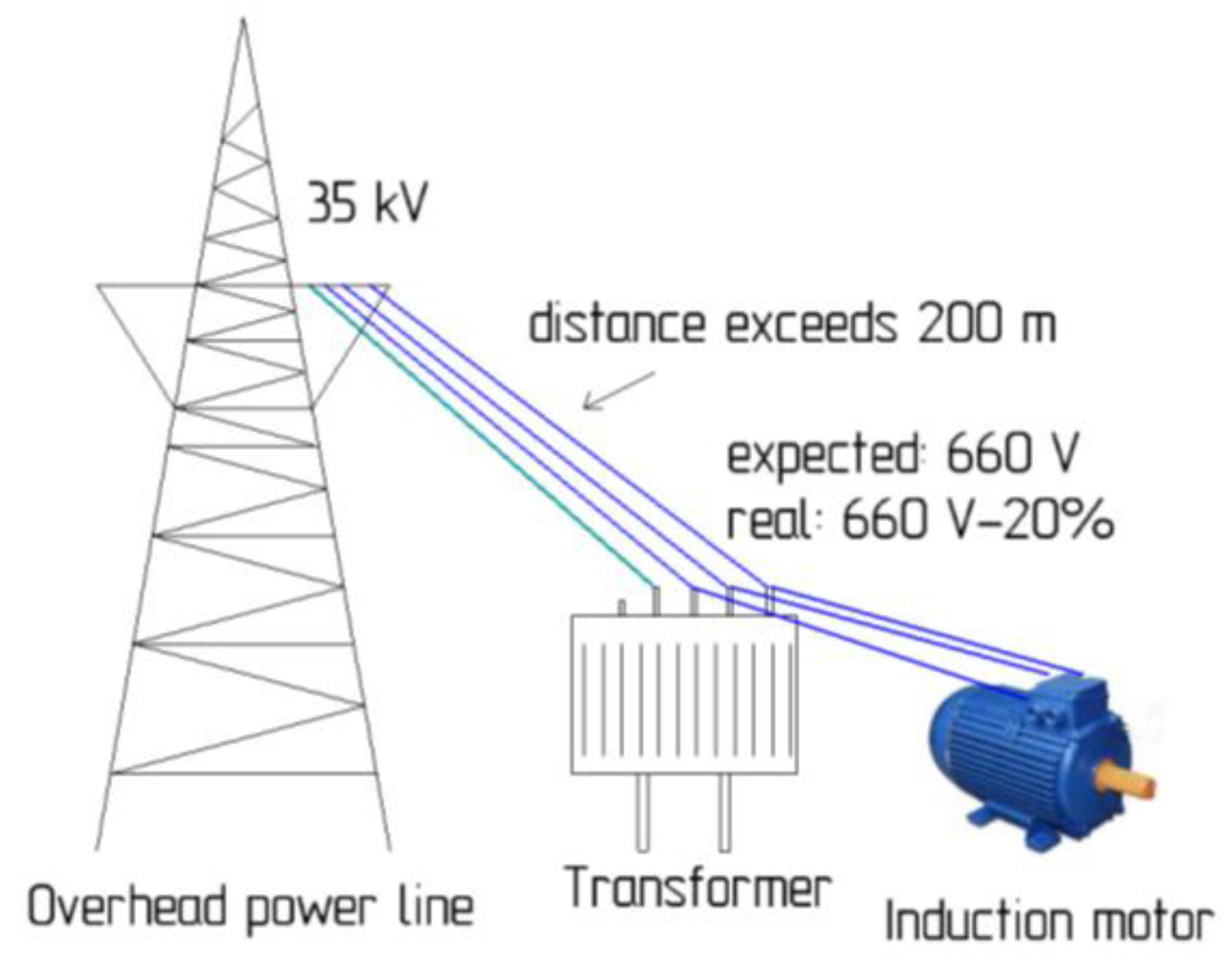
Electrically driven power plants, monitoring, and diagnostic systems in Asia and Australia are often located in areas remote from industrial power grids. For such conditions, it happens that the power of the electrical energy source becomes commensurate with the power of the electric drive due to losses in an extended network of power lines [
1]. The length of the long line exceeds the permissible length and the condition of the power lines is poor, causing the voltage to drop in the remote industrial facility—
Figure 1. Therefore, it is necessary to either use additional stand-alone power sources that form a combined power supply system for the electric drive, or use various methods of starting the electric drive. These methods include power supply from a diesel or gas turbine power plant, an autonomous transformer, reactor start-up of an electric drive, the use of a synchronous generator, and uninterruptible power supplies. Despite the wide range of the listed methods for starting an electric drive in remote areas, each of them comes with several disadvantages. Most of these disadvantages, such as inefficiency, pollution, and dependence on other raw materials, have been considered in previous works, but now it is proposed to consider the disadvantages of using rechargeable batteries as a stand-alone sources [
2].
In many industries, especially mining and metallurgy, fuel power supplies with high reliability are required for starting electric motors under load. Uninterruptible Power Supplies (UPS) are used to improve power quality and ensure reliability of emergency power supply. During power outages, energy must be provided by local energy storage systems. A UPS-based energy storage system mainly relies on the selection of a good lead–acid battery. However, batteries have many disadvantages, such as low power density and limited charge/discharge cycles. Moreover, the battery life may be shortened if it is fed with pulsed energy rather than average energy. In addition, current fluctuations cause voltage transients, surge currents have a higher root mean square (RMS) value that can lead to increased battery losses, and pulsed currents significantly shorten battery life. For this reason, it is proposed to replace the lead–acid based batteries with supercapacitor blocks [
3,
4].
A supercapacitor is an electrochemical double layer capacitor that can store thousands of times more energy than a conventional capacitor. It has the same characteristics as batteries and conventional capacitors, but has an energy reserve of about 20% compared to a battery. However, it also features low losses and a long service life. It can handle a large number of charge and discharge cycles—several hundred thousand cycles compared to a few thousand cycles for lead–acid batteries—and can deliver much higher currents than batteries [
5,
6,
7].
Batteries are most efficient when used for low, reasonably constant power. Supercapacitors are very efficient at storing charge for later use in startup mode.
It is worth noting that supercapacitors are in the development stage and are becoming more competitive in price.
Supercapacitors offer high power density at low energy cost and are a cost-effective solution for medium power stages where no power source is available and a buffer source is needed.
The use of supercapacitors as buffer power sources is considered in many papers, but there are a number of issues that have not been considered [
8,
9,
10]. In particular, only the static characteristics of the electric drive are evaluated, and the operation of the motor in dynamics is not considered. In addition, these works focus on the recuperation mode of operation without considering the motor start-up in the presence of network drawdown and without evaluating the motor dynamics. The motor models are taken from the standard Matlab Simulink library, where simplified models built only according to the main technical parameters and not allowing to accurately trace the dynamics of the transient processes occurring in these models. Moreover, there are cases where a block of supercapacitors is connected through the Generator–Drive system, without using a frequency converter, which reduces its effectiveness, since the use of a frequency converter affects the control of the electromagnetic torque, which is important during start-up [
11].
In other works, great emphasis is placed on considering the transient processes that occur in supercapacitors in their charging and discharging modes, but there is no analysis of the effects of supercapacitor blocks on the dynamics of an induction motor [
12,
13,
14,
15,
16]. In this context, it was decided to study the dynamics of the operation of the electric drive during start-up and power supply by a combined buffer system based on supercapacitor blocks.
2. Induction Motor in a Rotating Coordinate System with a Buffer Source Supply
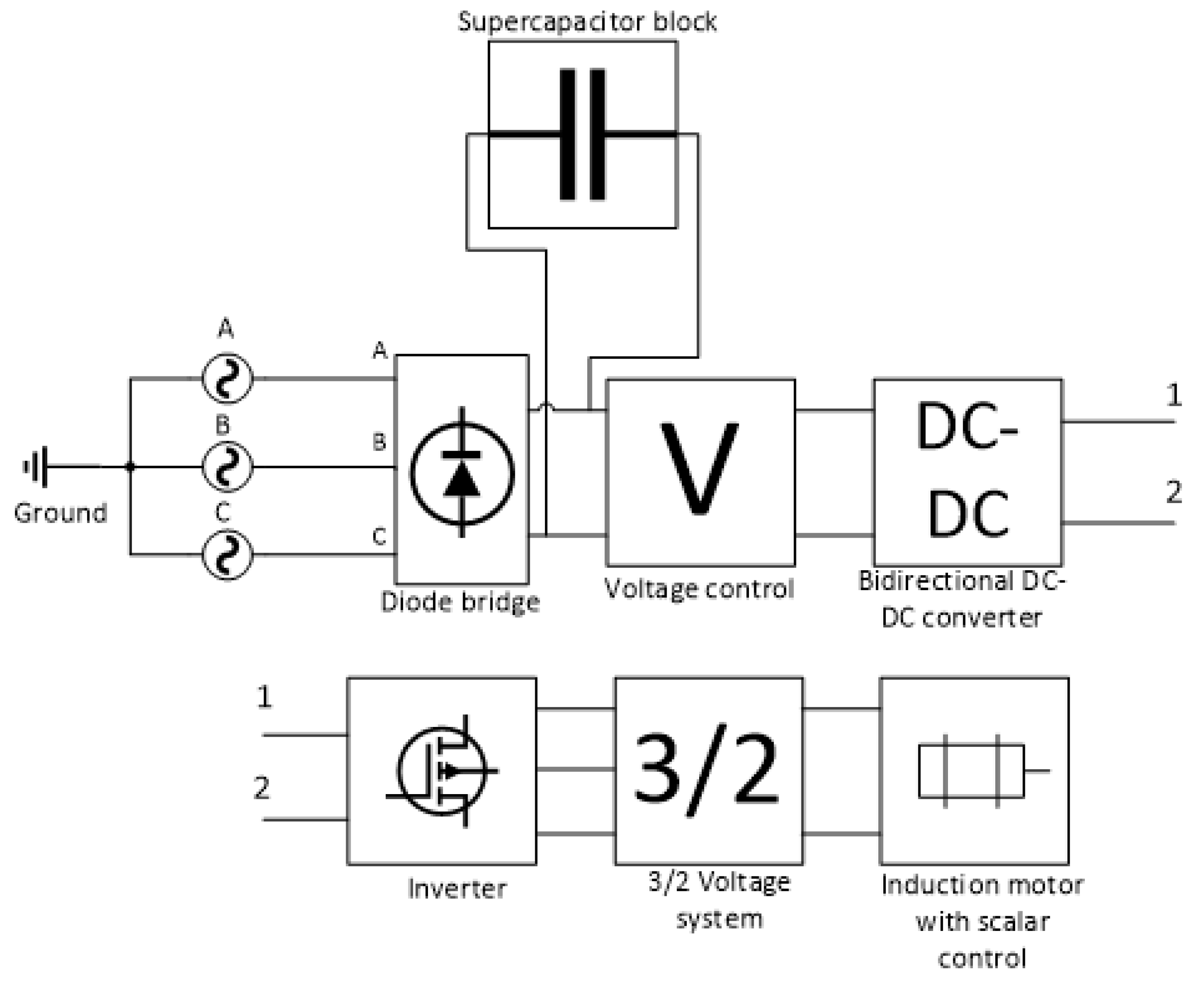
The research object of this article is the power supply system of a frequency-controlled induction motor and a buffer power supply system based on supercapacitors. The analysis of their connection is carried out on the basis of the mechanical properties when the motor is started under load. The resulting speed and torque curves provide the reference signal for the drive control system to control the speed of the motor and, thus, supply it with power. Once the speed, relative position in space and load were determined, the buffer power source system was selected and calculated. This system consists of several banks of supercapacitors connected to the DC link of the frequency converter. In this work, the simulation model of a buffer power supply based on supercapacitors has been improved compared to previous versions of the model by adding the possibility to recharge the supercapacitor blocks by connecting them through a bidirectional DC–DC converter—
Figure 2 [
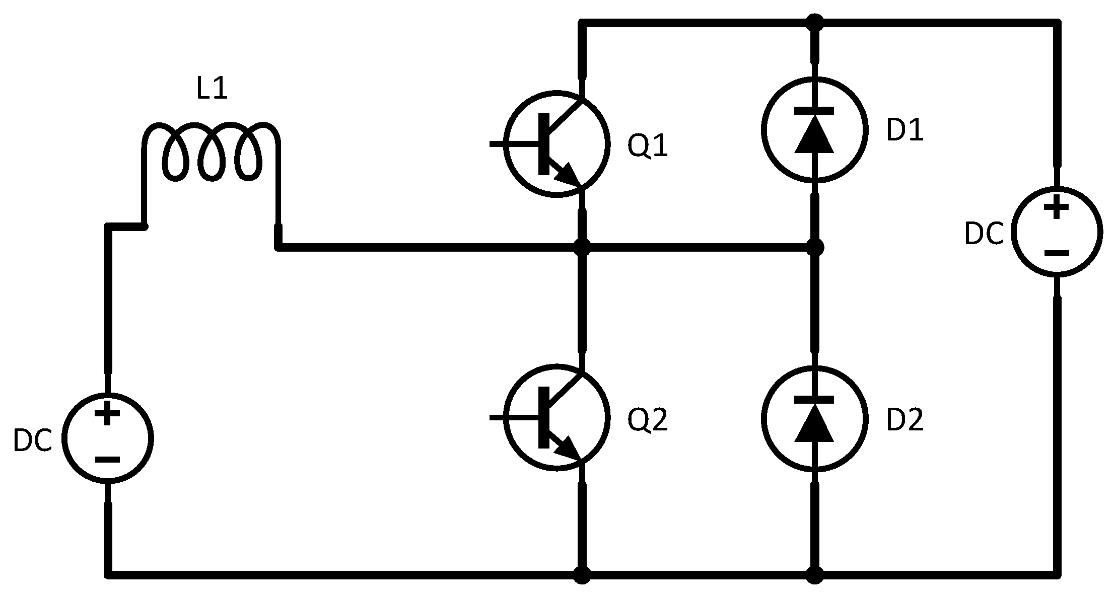
2]. The flow of energy from or to the buffer must be controlled according to the power management requirements. The converter operates either in boost mode during power delivery from the buffer to the DC line or in buck mode during buffer charging [
17].
The block of supercapacitors provides the peak power to the electric motor during its start-up in the event of a drawdown in the supply network. The supercapacitor recharges the energy during start-up without dropping the mains voltage.
The bidirectional DC–DC converter is a connection method between the storage device, which is part of the buffer power supply control system, and the DC link, it must be bidirectional to allow current to flow in both directions, corresponding to the discharge or charge cycle block of supercapacitors.
In this paper, an AIR160S4 asynchronous electric motor is considered with the following parameters listed in
Table 1.
The induction motor model is powered by a three-phase source, and a frequency converter with scalar control provides its regulation.
This converter consists of the following parts: a rectifier, a buffer power source based on supercapacitors with a control system, and an inverter based on MOSFET transistors.
In this work, a conventional diode rectifier is used, but it is planned to improve it in the future to increase the quality of energy conversion by adding modulation to the rectifier circuit. Modulation will be added using controlled current or voltage sources [
18].
Generally, a three-phase voltage system is applied to the stator winding, which is 120 degrees offset from each other. The total voltage vector is equal to the sum of the voltage vectors of the individual phases, as seen in Formula (1).
The vector projections on the phase axes determine the instantaneous voltages on each of the phases A, B, and C. All equations of current and flux linkage that describe the operation of an asynchronous AC motor can be described in the same way.
However, during the creation of real AC motor systems, 3/2 phase converters are often used. A 3/2 converter from a three-phase voltage system A, B, and C creates a two-phase
α and
β. The transition to a new two-phase system allows us to consider the space vector in a Cartesian coordinate system. Such a change of variables is used in the mathematical description of electrical machines to simplify the solution and writing of differential equations of the stator and rotor, Formula (2) [
19].
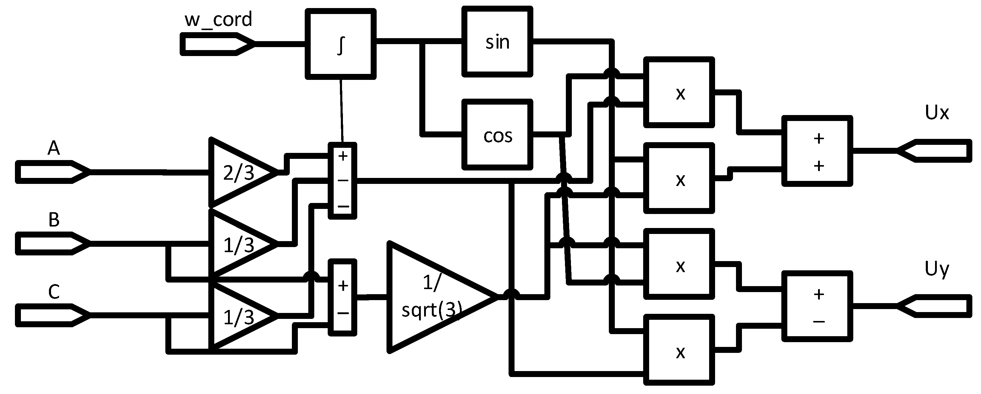
After receiving the frequency-converted supply signal from the output of the frequency regulator, the voltage is converted from a three-phase sinusoidal to a two-phase one to create a model of an asynchronous motor in a rotating coordinate system—
Figure 3. As a result, the phase voltage
,
, and
is converted into
and
.
The resulting two-phase voltage is used to power the asynchronous motor model in a rotating coordinate system.
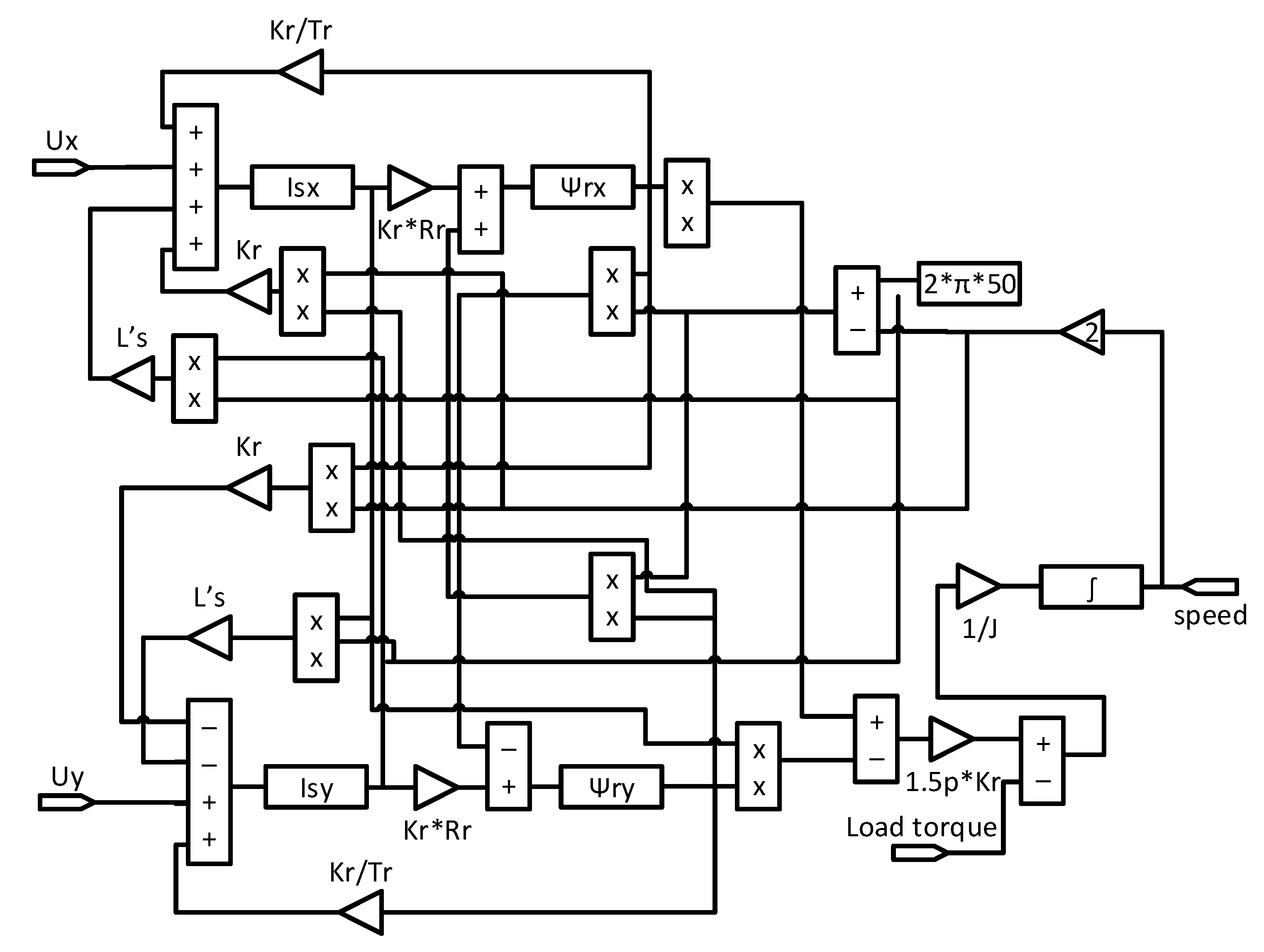
The system of equations for describing an asynchronous AC machine is based on four laws—Kirchhoff’s second law, Ampere’s law, Newton’s second law, and Lenz’s left-hand rule and is indicated in Formula (3).
After the transformation, the following equations can be obtained as Formula (4).
Based on the system of Equation (4), a model of an induction motor was calculated and developed, this model is shown in
Figure 4.
2.1. Algorithm of the Control System Operation for the Buffer Source of Electricity
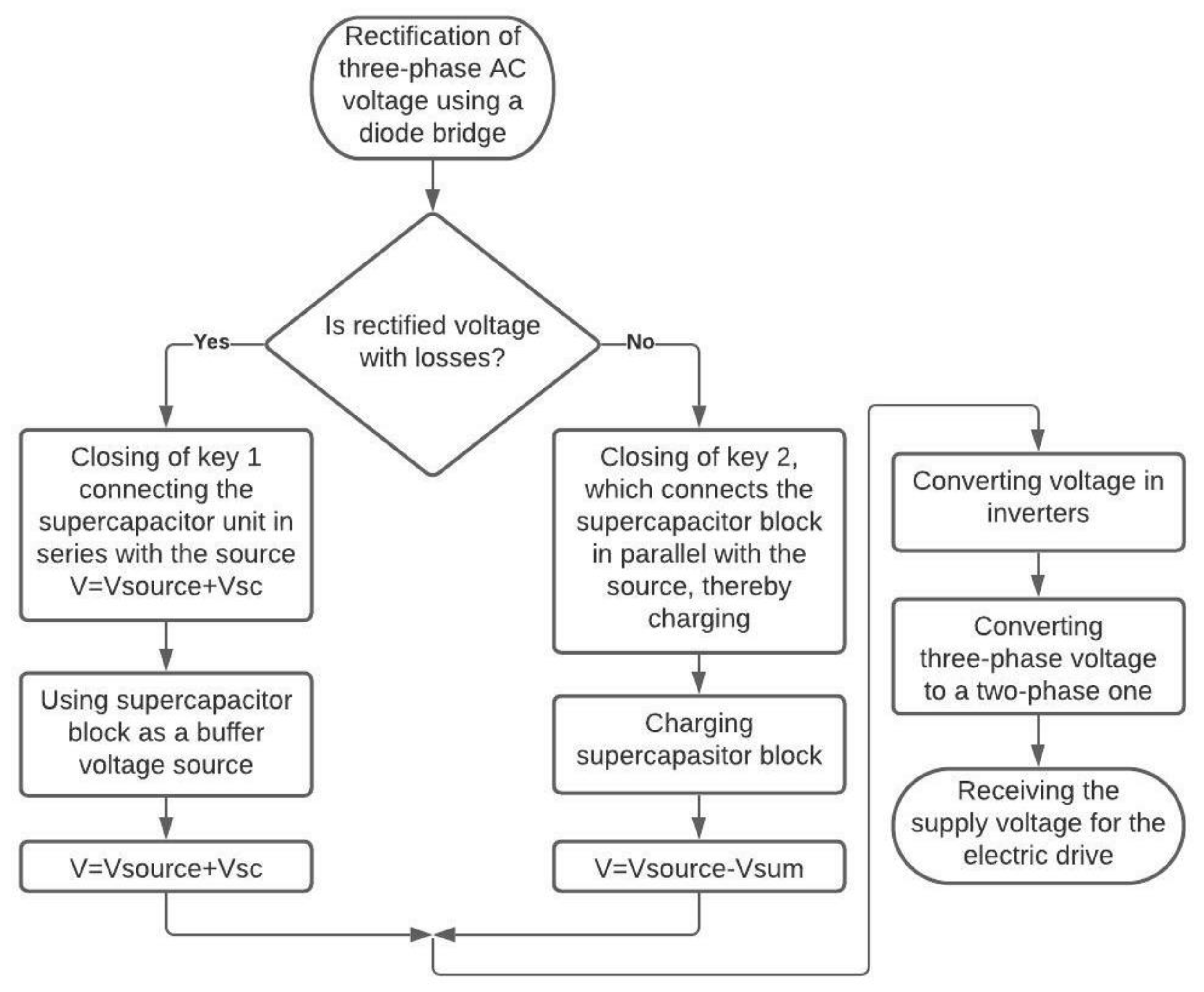
In order that the supercapacitor block is not constantly connected to the DC of the frequency converter, i.e., its supply of electricity was not wasted, and also to have the possibility of automatically charging this unit, an algorithm for the control system of a buffer source of electricity based on supercapacitors has been developed—
Figure 5.
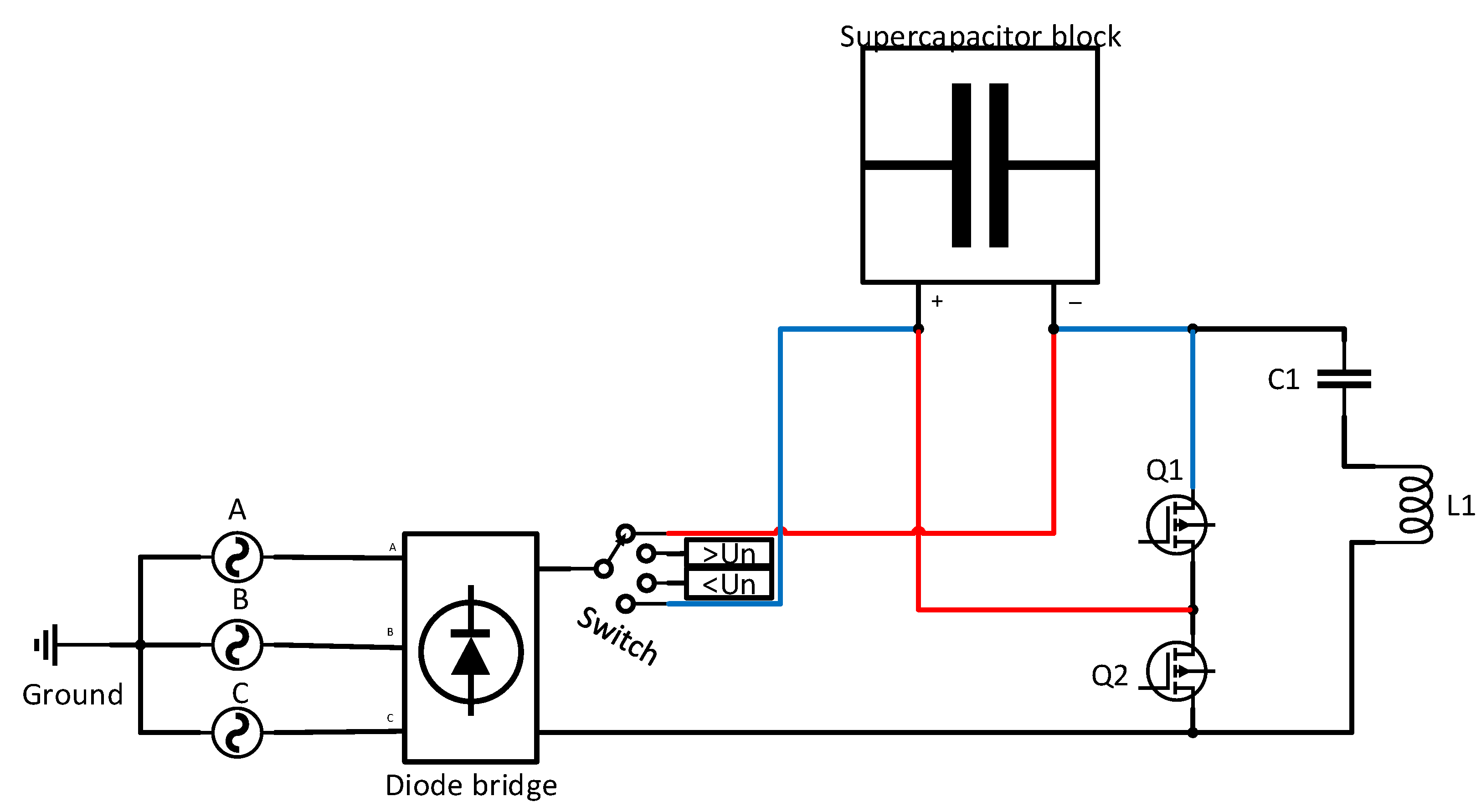
If the rectifier voltage is below the nominal voltage preset in the control system, the key that connects the buffer power supply system based on supercapacitors is closed—
Figure 6, red signal. As a result, the rectified supply voltage is connected in series with the supercapacitor block. The rectified voltage is added to the voltage output from the supercapacitor unit via a bidirectional DC–DC converter. The total rectified voltage is passed to the inverter system for further conversion.
Otherwise, if no voltage drop occurs when comparing the rectifier voltage with the nominal voltage (the rectifier voltage is greater than or equal to the nominal voltage), the key system connects the supercapacitor block for charging—
Figure 6, blue signal—and the supercapacitor block is included in the supply voltage circuit in parallel. When the SOC (state of charge) supercapacitor block reaches 100% charge, the charging process is terminated. All discharging and charging processes of the supercapacitor block are explained in the chapter “Simulation Modelling”.
2.2. Calculation of a Supercapacitors Block
It was chosen that supercapacitors added as energy storage should provide additional buffer power for 30 s when the drive is started.
To calculate the equivalent capacity of a block consisting of several supercapacitors of its own capacity, the following formula is applied [
12]:
where
is the equivalent capacitance of the supercapacitor block,
I is the current flowing through the supercapacitor block,
U is the voltage of the given block, and
t is the time.
To calculate the number of supercapacitors connected in series in a block, the following formula is used:
where
is the voltage of one supercapacitor,
is the number of supercapacitors in the block connected in series.
The value is rounded to the nearest integer. In this case, the capacity of one supercapacitor in the block should be:
where
is the capacity of one supercapacitor.
According to these parameters, a Maxwell supercapacitor BMOD0058 E016 B02 (Yongin-si, Gyeonggi-do, Korea) was selected with the characteristics presented in
Table 2 [
20].
The following formula is used to calculate the number of parallel supercapacitors in a block:
where
is the number of supercapacitors in the unit connected in parallel and
is the current of one supercapacitor.
The final model of the system, consisting of a three-phase voltage source, a rectifier, a buffer power source and its control system, inverters, and a model of an asynchronous motor and its control, on which simulation modeling were carried out in this article, is shown in
Figure 7.
3. Simulation Modeling
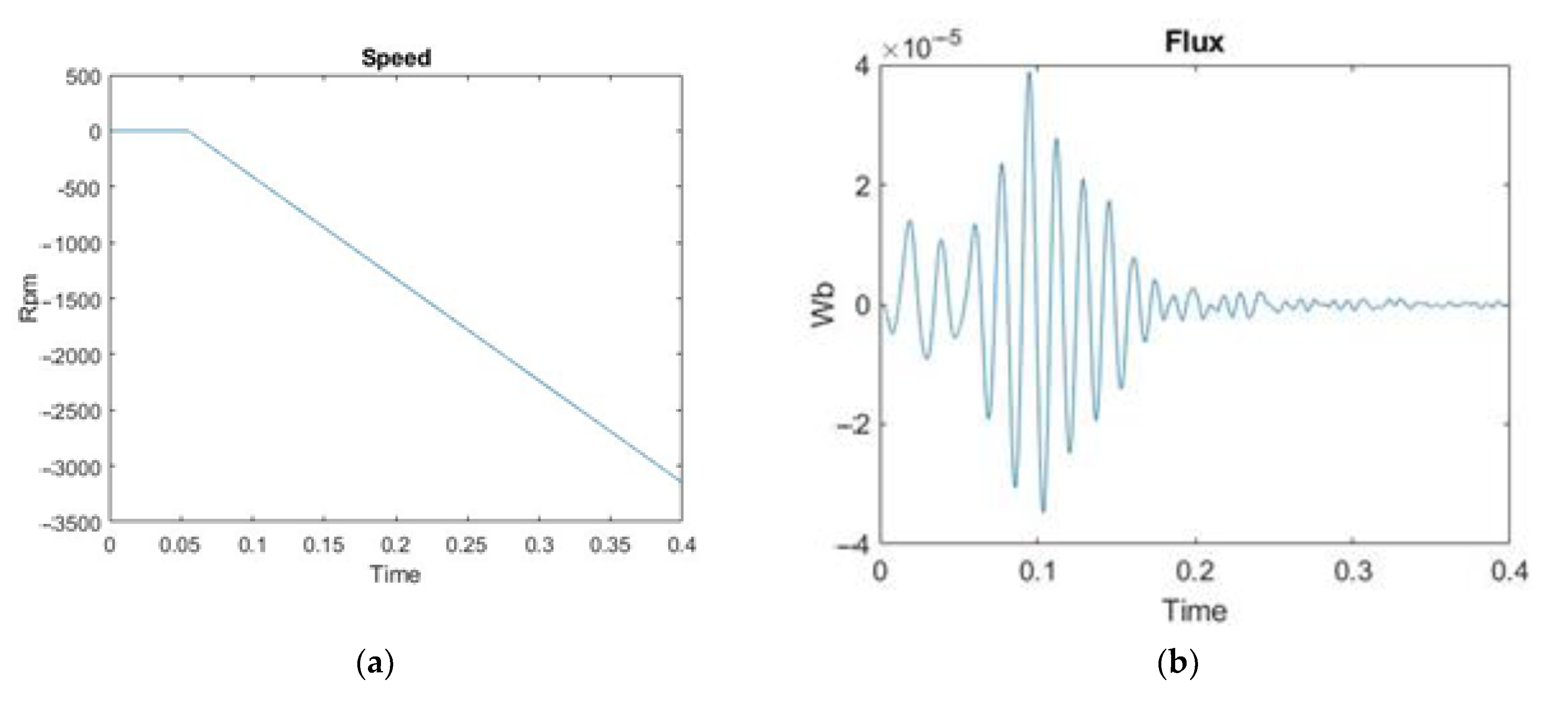
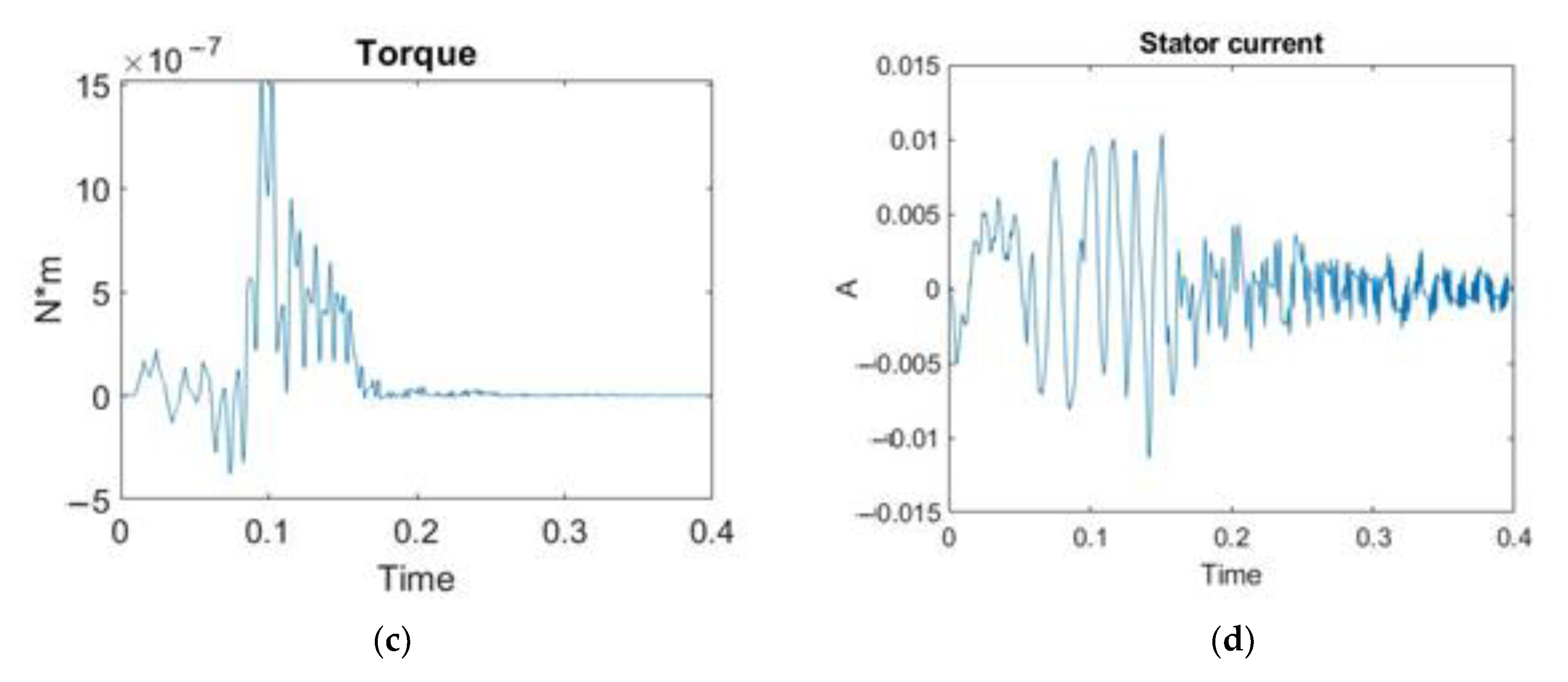
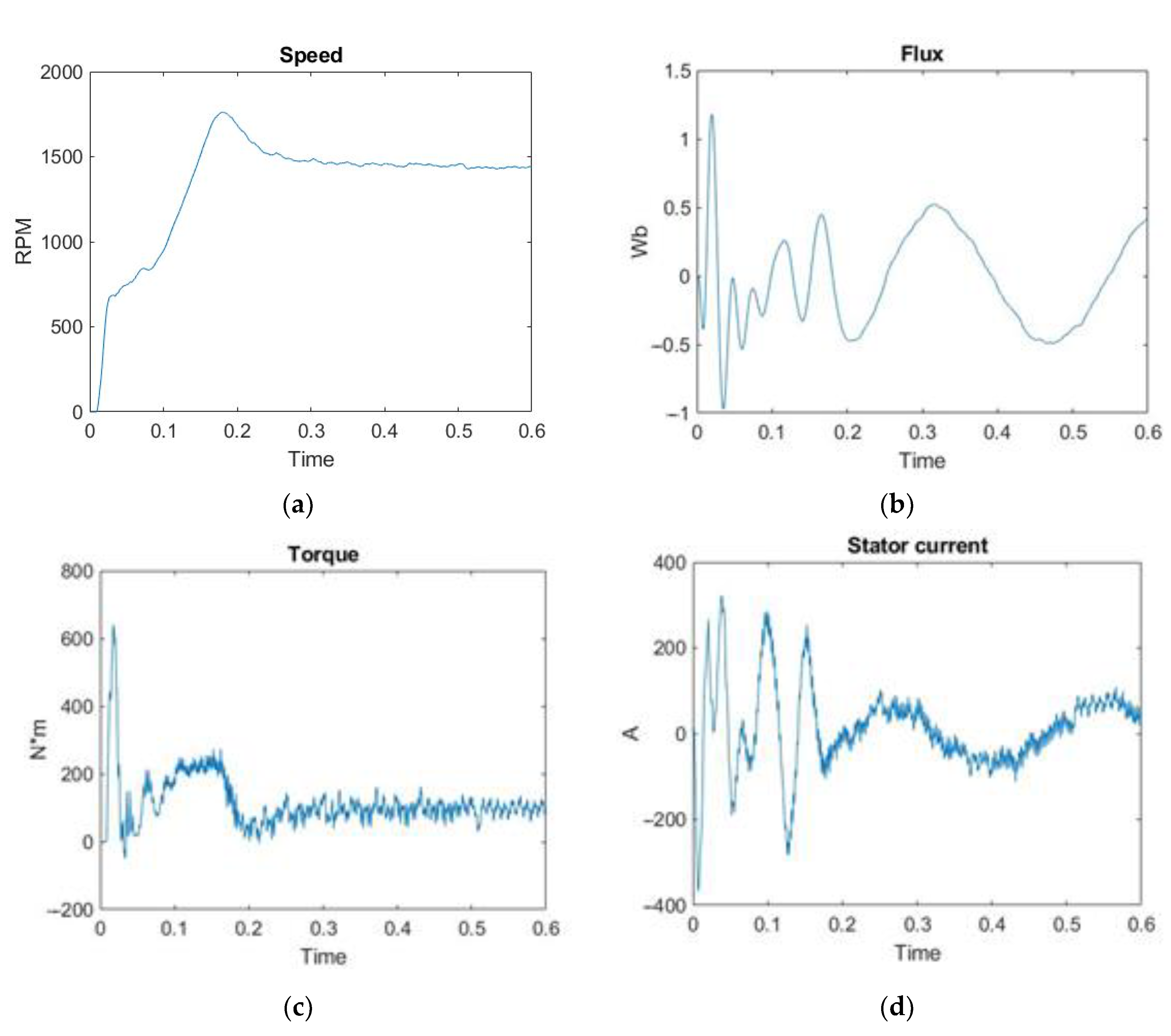
First, the simulation of the start-up modes of the electric drive without an additional buffer source of electricity was performed to compare its dynamic characteristics. The simulation of the voltage drop is realized by changing the input value by 20% less.
Scopes of the motor transient processes at rated voltage—
Figure 8 and voltage less than the rated one by 20%—
Figure 9 without using a supercapacitors block as a buffer source of electricity are shown below.
As can be seen from these scopes, the motor over-revs at a voltage drop of up to 20% at the moment of connecting the rated load at 0.055 s, indicating the need to connect an additional power source to start the electric drive under load.
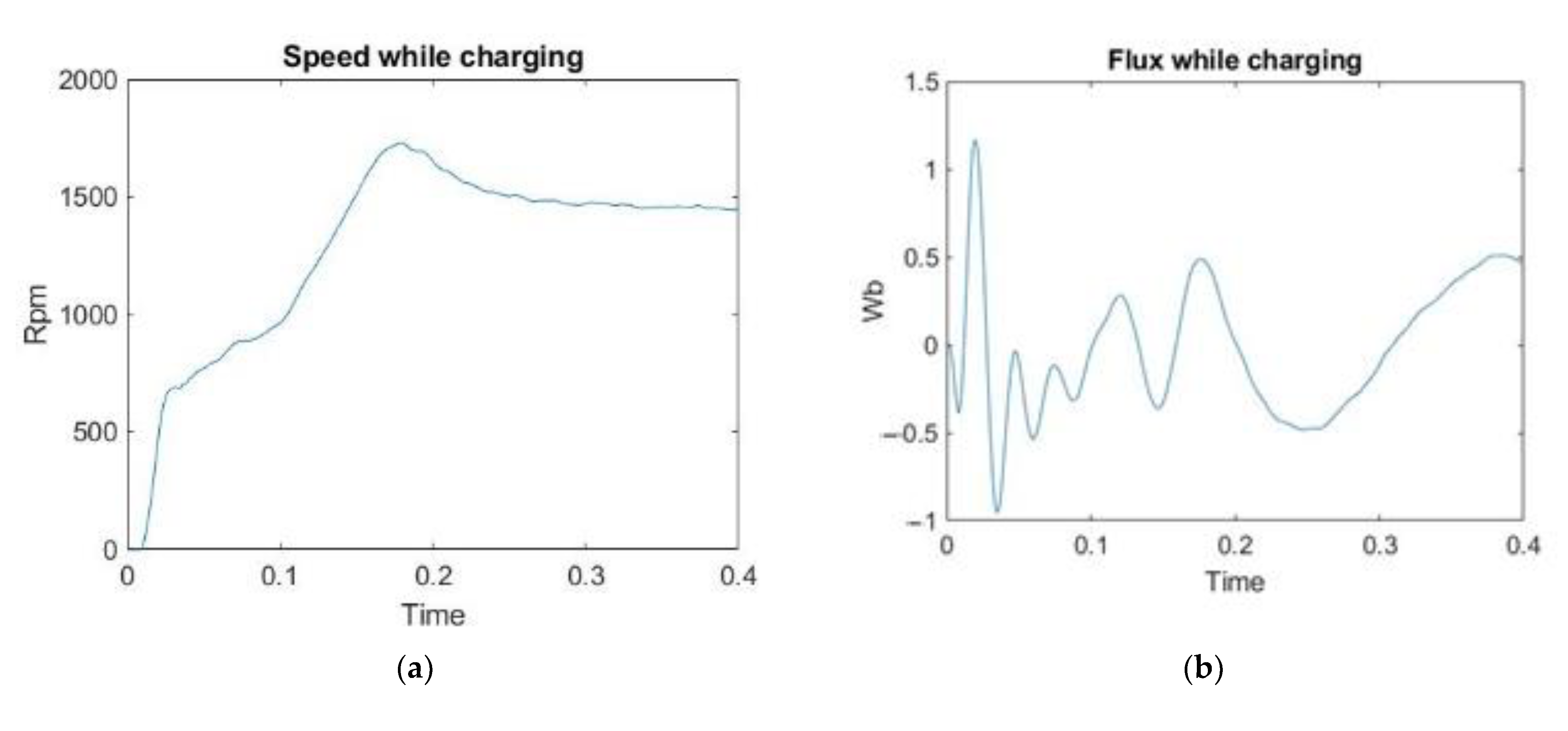
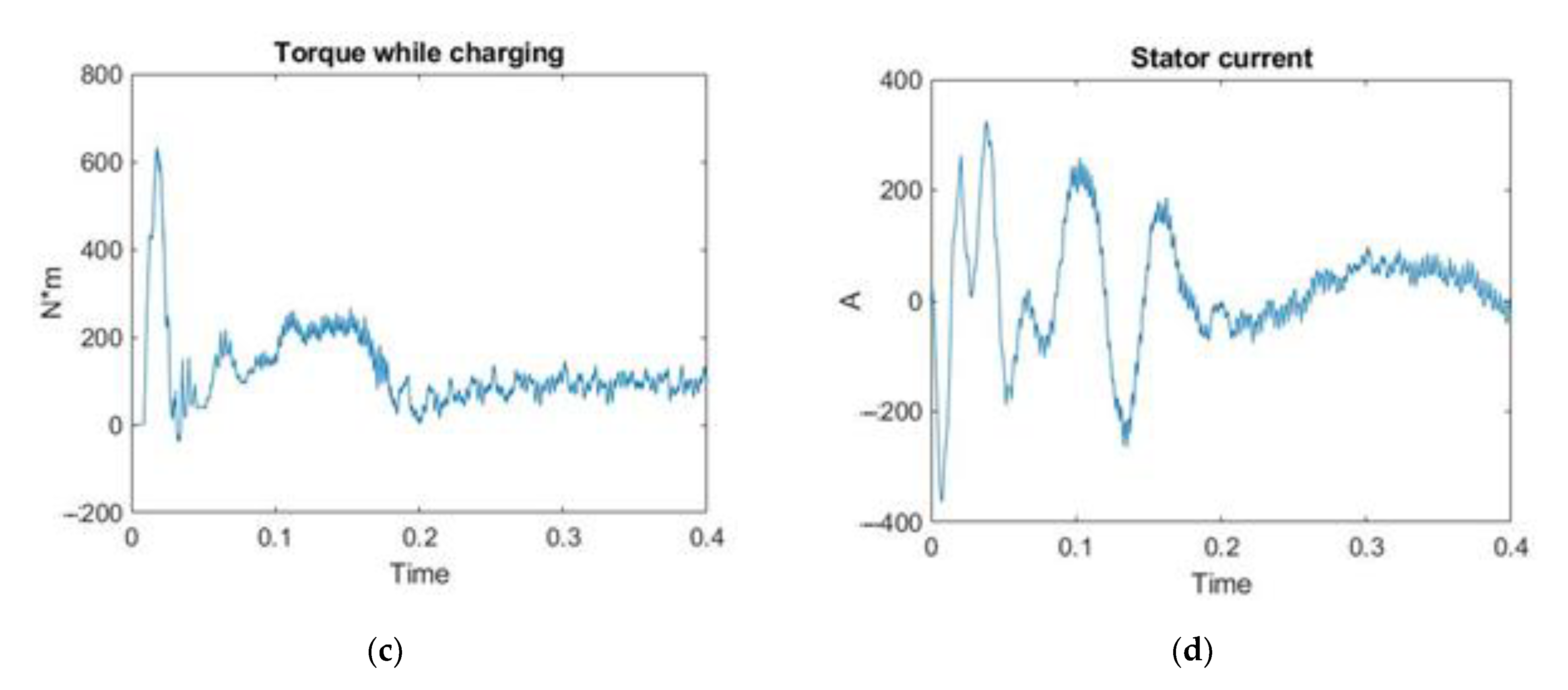
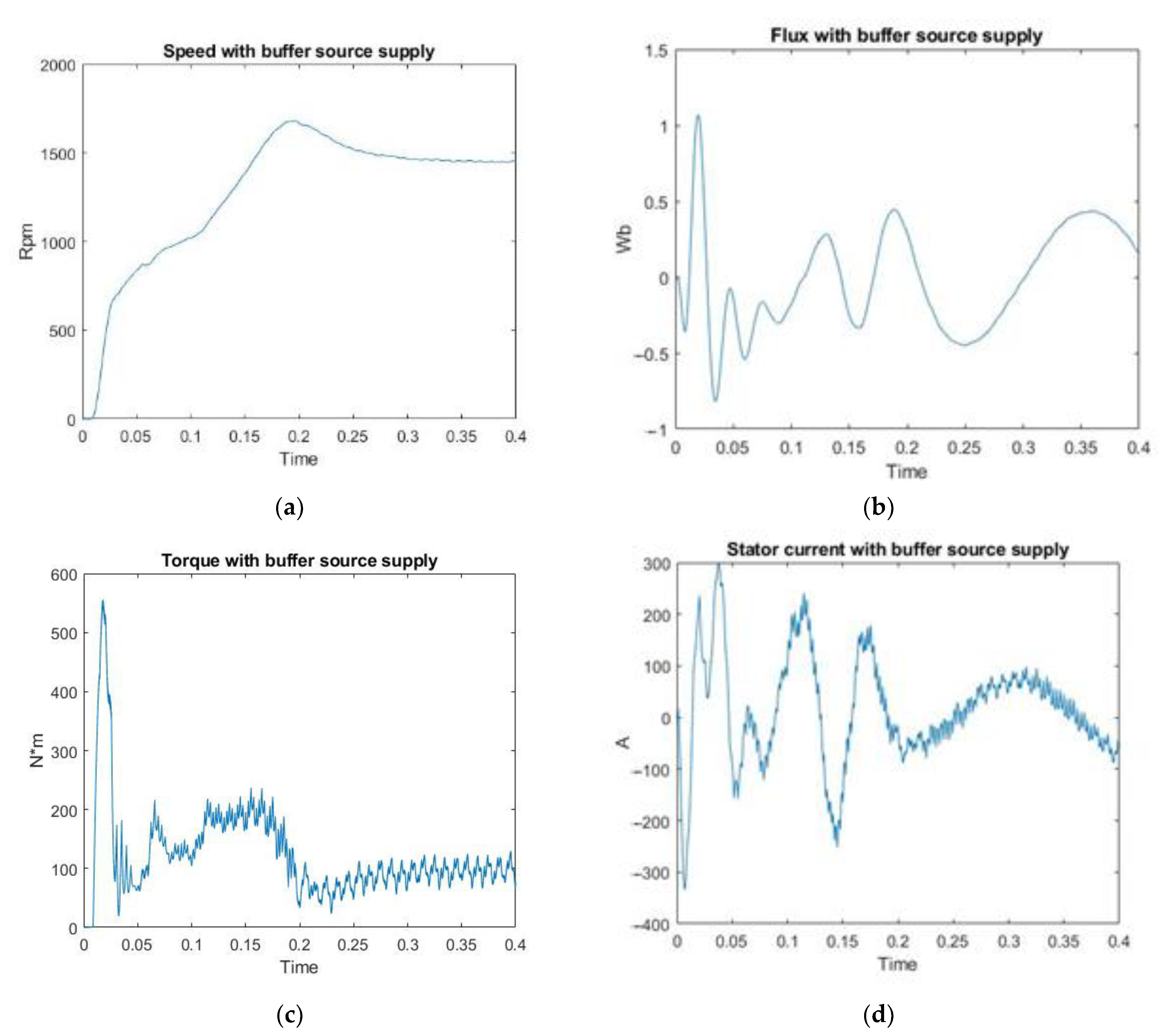
Then, a simulation was performed for starting an induction motor under load at a rated supply voltage—
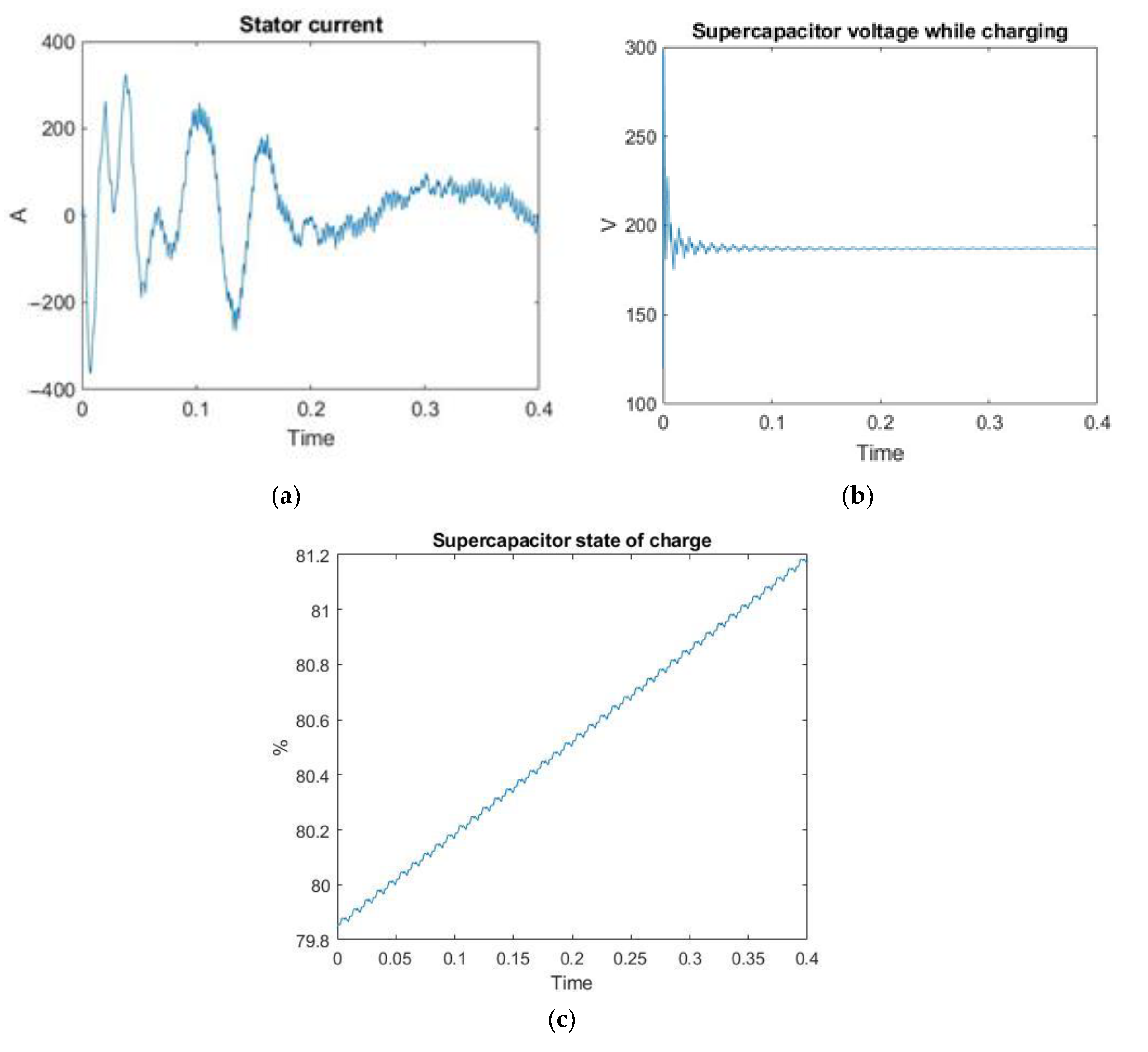
Figure 10—with a buffer power supply connected based on a supercapacitor unit. At the nominal supply voltage, the control system for the buffer power source starts the supercapacitor bank recharging system. The transient processes occurring in the supercapacitor block are shown in
Figure 11.
When the supercapacitor unit is charging, it consumes a voltage of 170 V, which is the total voltage of this unit calculated above, consisting of 10 supercapacitors connected in series. When 100% of the SOC% charge of the supercapacitor is reached, the control system disconnects the supercapacitor unit from the parallel connection with the mains and the charging process is terminated. The charging time of the supercapacitor bank from fully discharged to 100% with parallel operation of the electric motor is about 40 s. At the same time, the scope of the power dynamic characteristics of the motor shows that the parallel charging of the supercapacitor block from the same source as that of the electric motor has no noticeable effect. Only the oscillation of the torque increases within 10%.
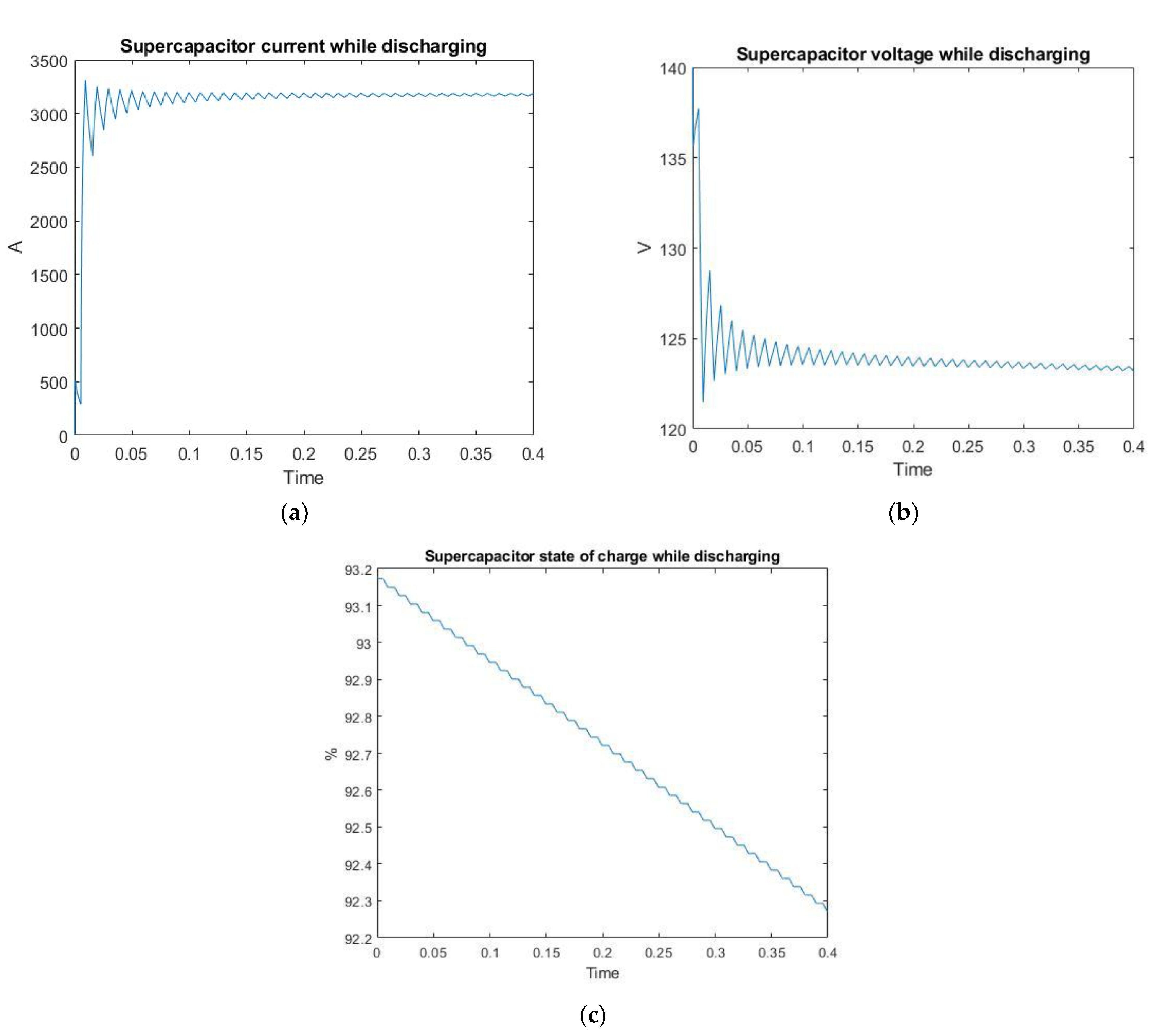
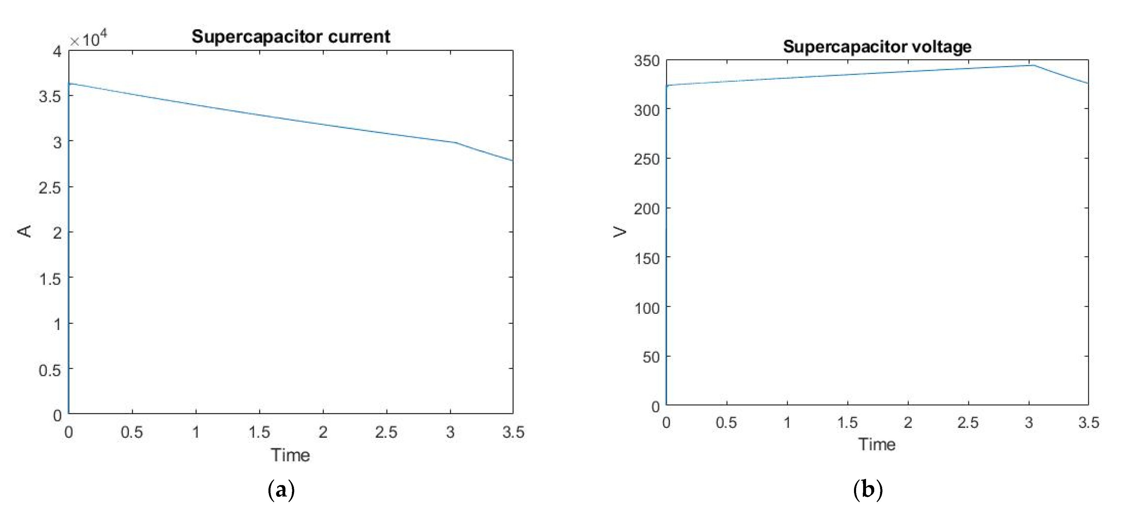
In the second case, with a voltage drop of up to 20%, the control system of the buffer power source includes a block of supercapacitors in series in the DC link of the frequency converter, obtaining an additional buffer energy equal to the charge of this block. The transient processes occurring in the supercapacitor unit in this case are shown in
Figure 12 and
Figure 13.
The selected supercapacitor bank starts supplying 110 V to compensate for network losses. After simulation, a 100% charged supercapacitor bank will last about 50 s to supply buffer power to the network until it is fully discharged. This is sufficient since power was originally assumed to be supplied for 30 s.
The analysis of the performance characteristics of the induction motor during supercapacitor bank charging shows that the time taken for the motor to reach steady state has increased by 0.05 s, which is 16.6% and is satisfactory for starting the motor under load. The overshoot during supercapacitor unit charging has increased from 14.2% to 25%, which also slightly affects the transient quality. In this case, the electrical characteristics of the motor—the rotor flux linkage and the stator current during charging have almost not changed. It can be concluded that the calculated supercapacitor bank, based on Maxwell BMOD0058 E016 B02, can be used as a buffer source of electricity in case of mains drawdowns up to 20%, as well as this unit can be charged from the mains in parallel with starting the motor at nominal mains voltage.
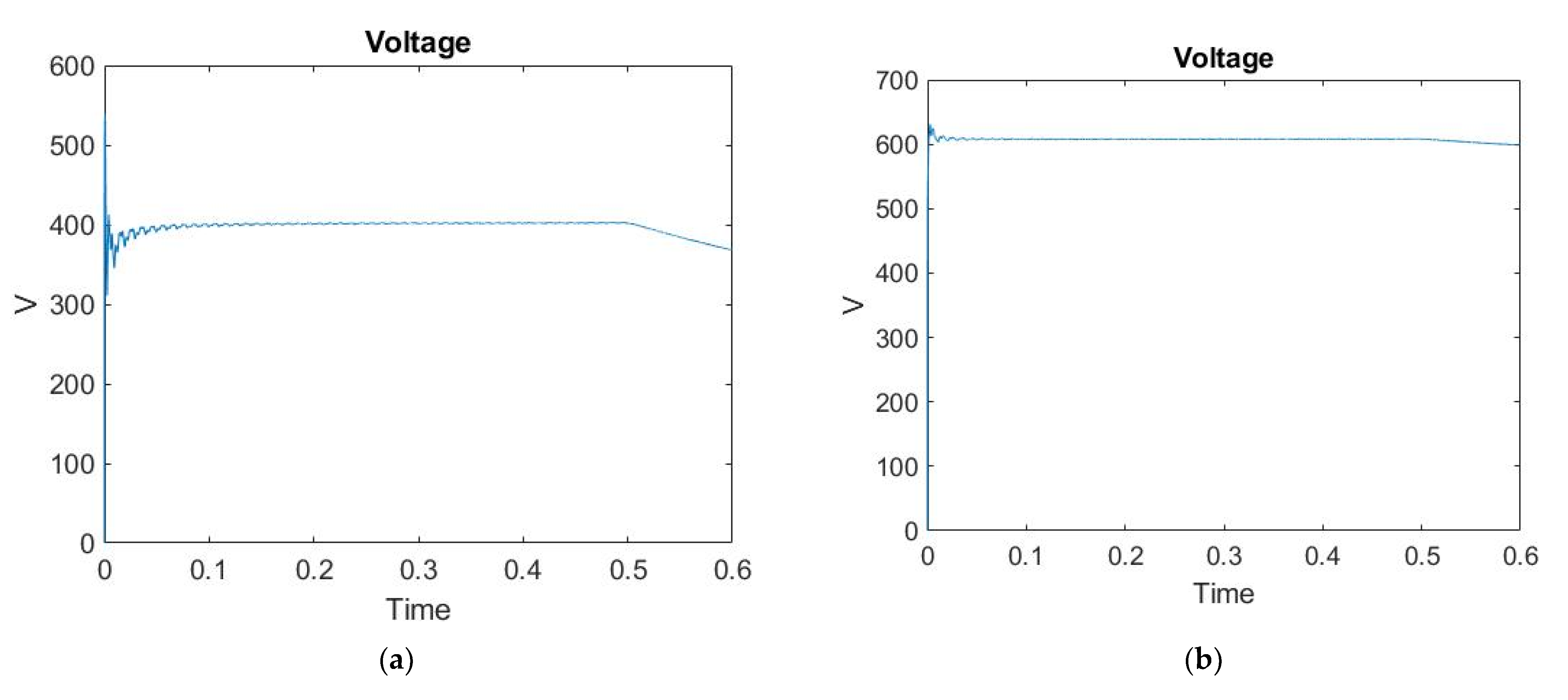
A simulation was performed with the voltage dropping from 400 V to 320 V. The characteristics were recorded showing the change in voltage at the input of the rectifier and after the inverter (
Figure 14).
The voltage drops at 0.5 s. After the fall, the supercapacitor unit begins to discharge and is used as a buffer source of electricity. At the same time, the characteristics that occurred in the drive were recorded—
Figure 15.
It can be seen from the figures that a slight voltage drop occurs at time 0.5 s, but thanks to the supercapacitor unit, the voltage is immediately recovered and the motor continues to operate at rated power.
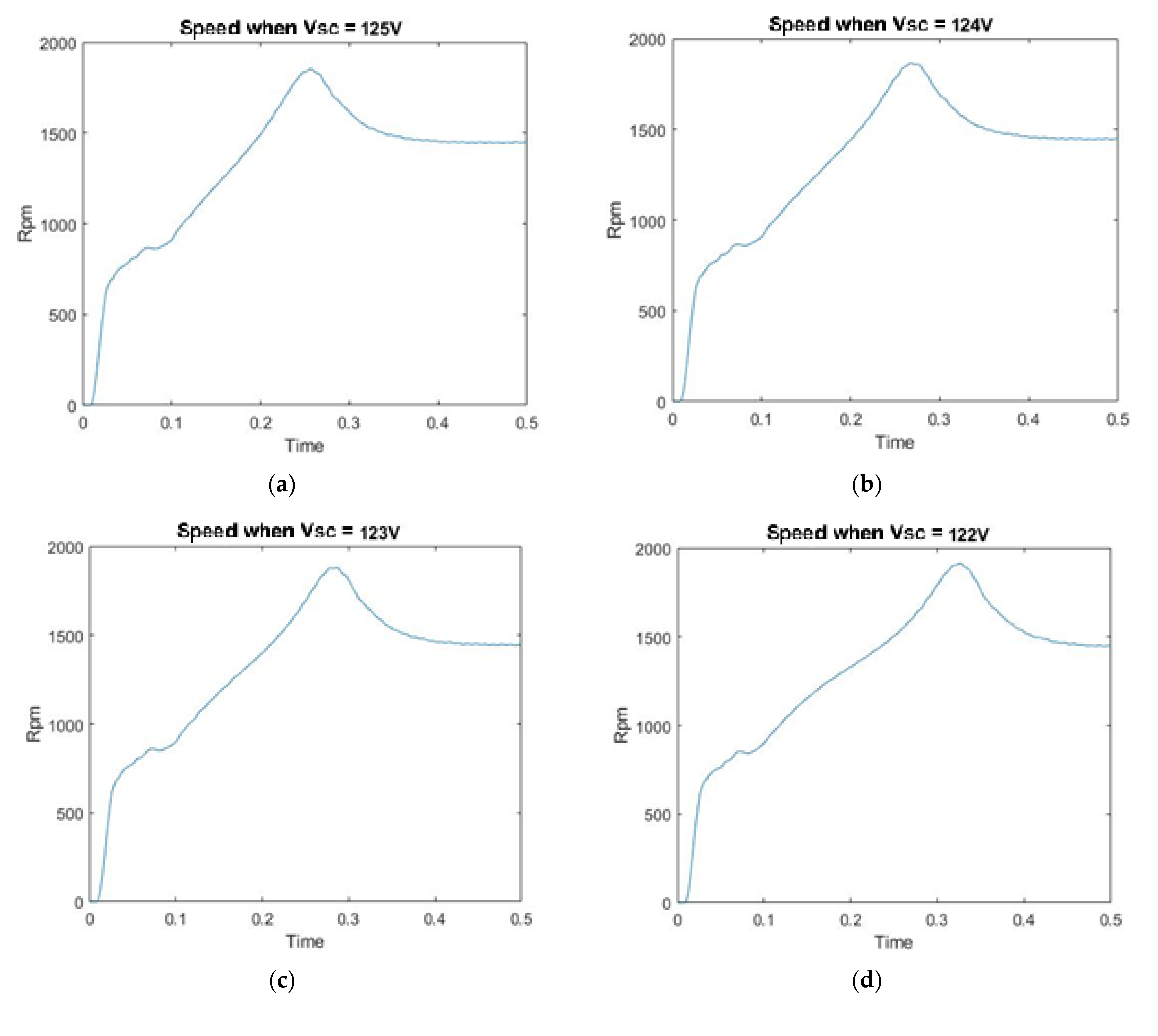
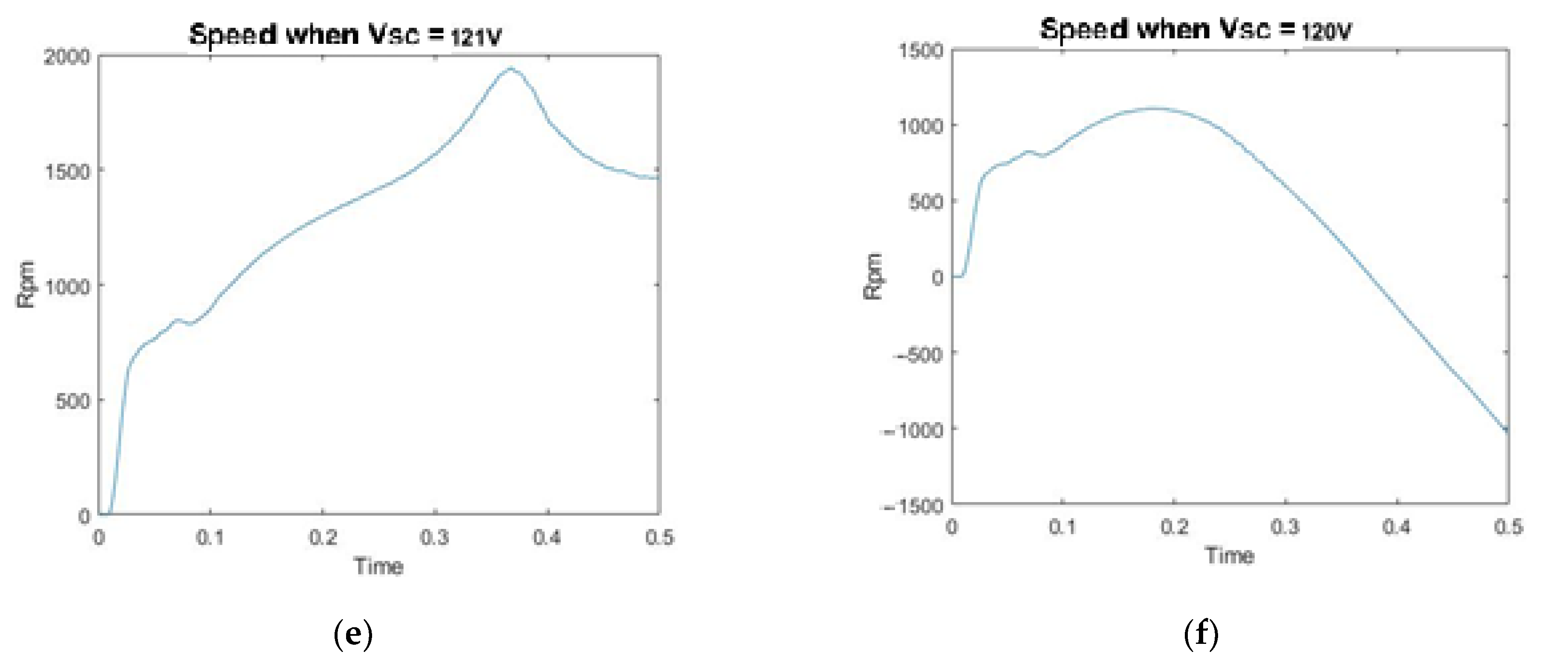
Further simulations were performed to determine other properties and characteristics of the supercapacitor unit. In particular, to determine the minimum allowable charge voltage of the supercapacitor unit, a series of simulations were performed in which the value of the current state of charge (initial value) changed. At the maximum value of the unit voltage of 150 V, significant changes in the dynamics of the transient processes in the electric motor occurred only when the current charge of the supercapacitor unit was 125 V. The transient acceleration processes are shown in
Figure 16.
As a result of the simulations performed, it was found that the minimum value of the state of charge of the supercapacitor unit is 121 V, which is 80% of the maximum charge value. With a current state of charge of 120 V and a network drawdown of 20%, this voltage is no longer sufficient and the electric drive cannot start. Therefore, it is proposed to charge the supercapacitor unit to this value before starting the electric motor.
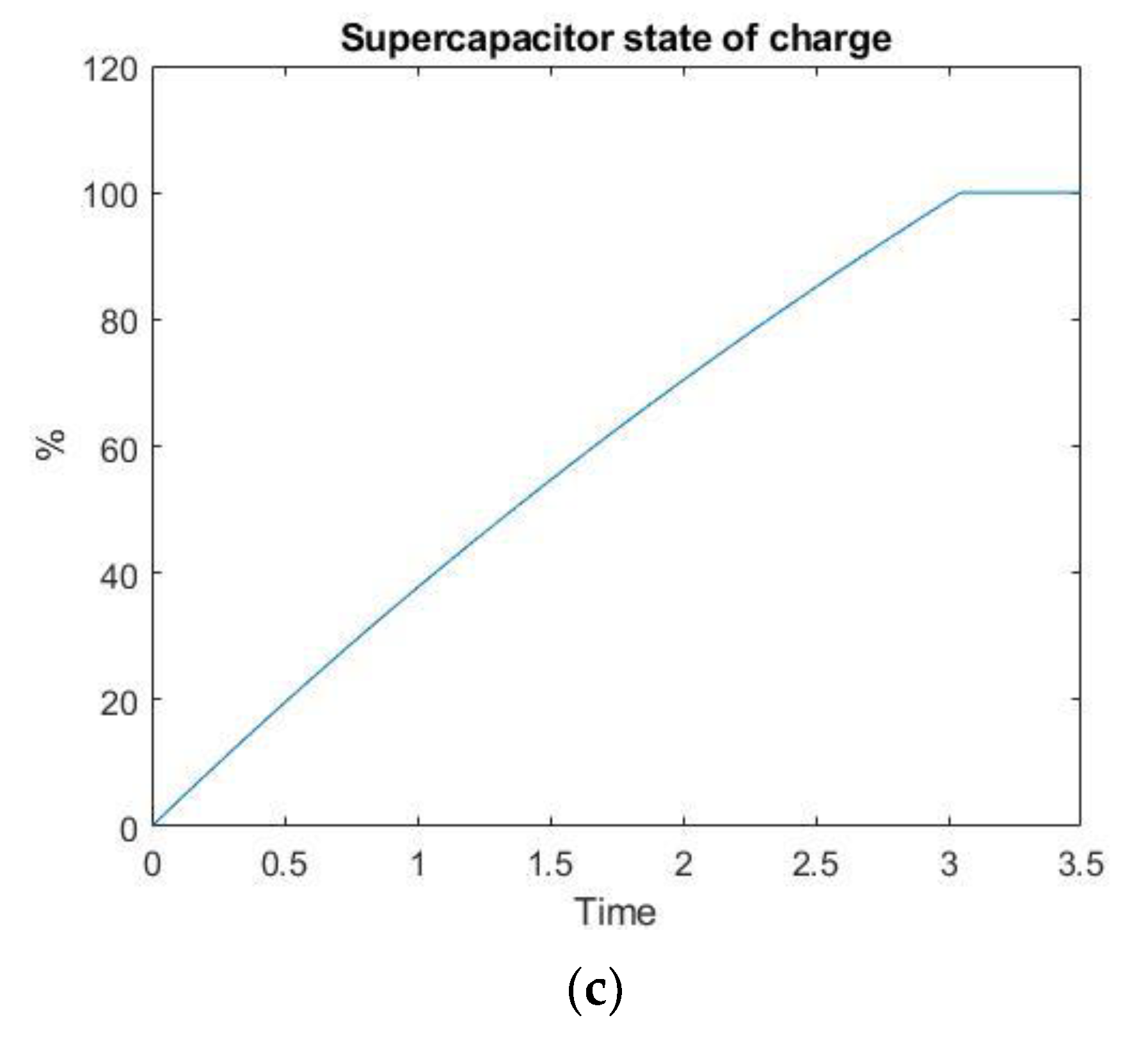
A simulation was performed to determine the starting delay resulting from charging the supercapacitor bank to 80%. The supercapacitor unit was charged from a fully discharged state to 80% when fed from a voltage source where a drawdown of 20% occurs—
Figure 17.
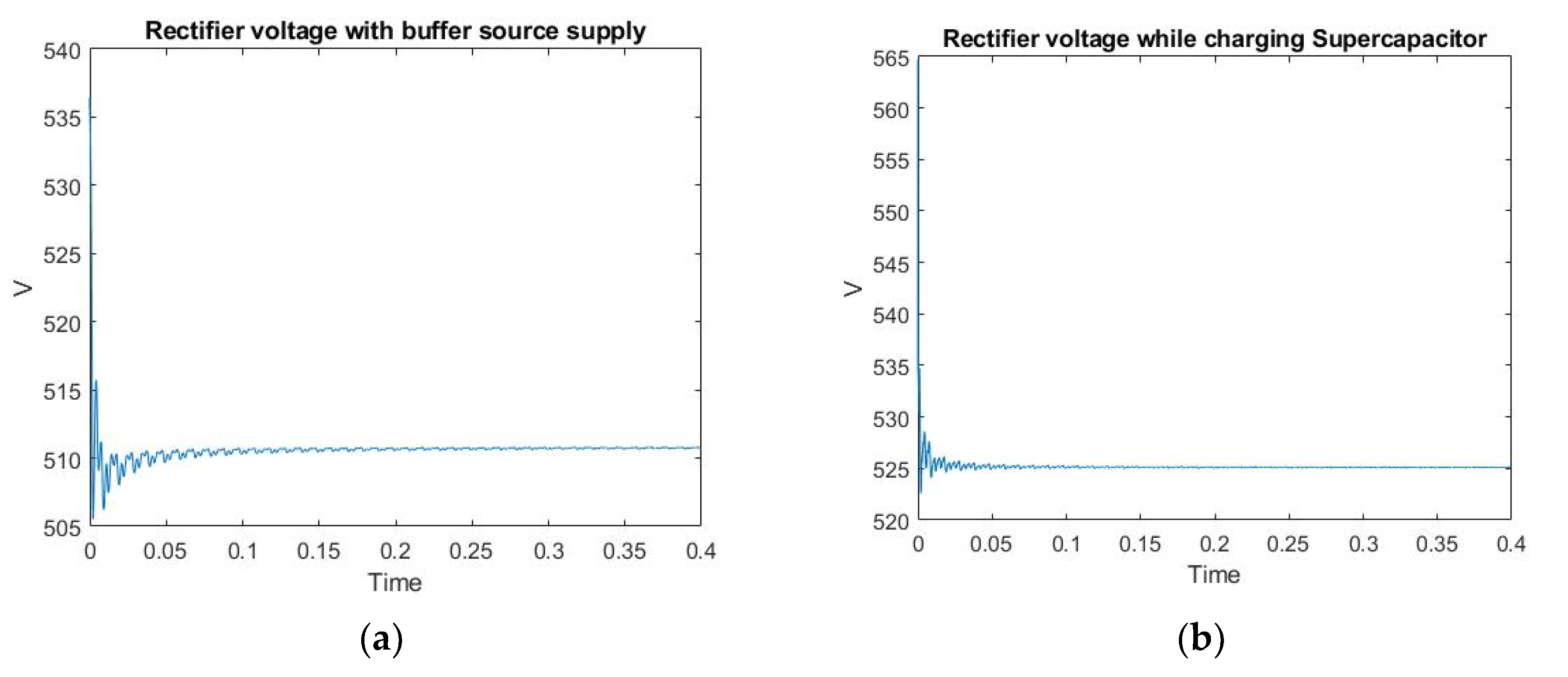
From the diagram shown, it can be seen that charging to the minimum required level of 80% takes 2.3 s and fully charging the supercapacitor unit takes 3 s, which has a negligible effect on the delay in starting the electric motor, and it is recommended that this be done before starting the electric drive itself. The scope showing the voltage coming out of the rectifier when the voltage drop occurs and the buffer source of electricity is connected, the oscilloscope shows the nominal value of the network voltage during the charging of the buffer source of electricity were taken—
Figure 18.
The difference between these values is 15 V, which also insignificantly affects the start of the electric drive under load, as defined above.
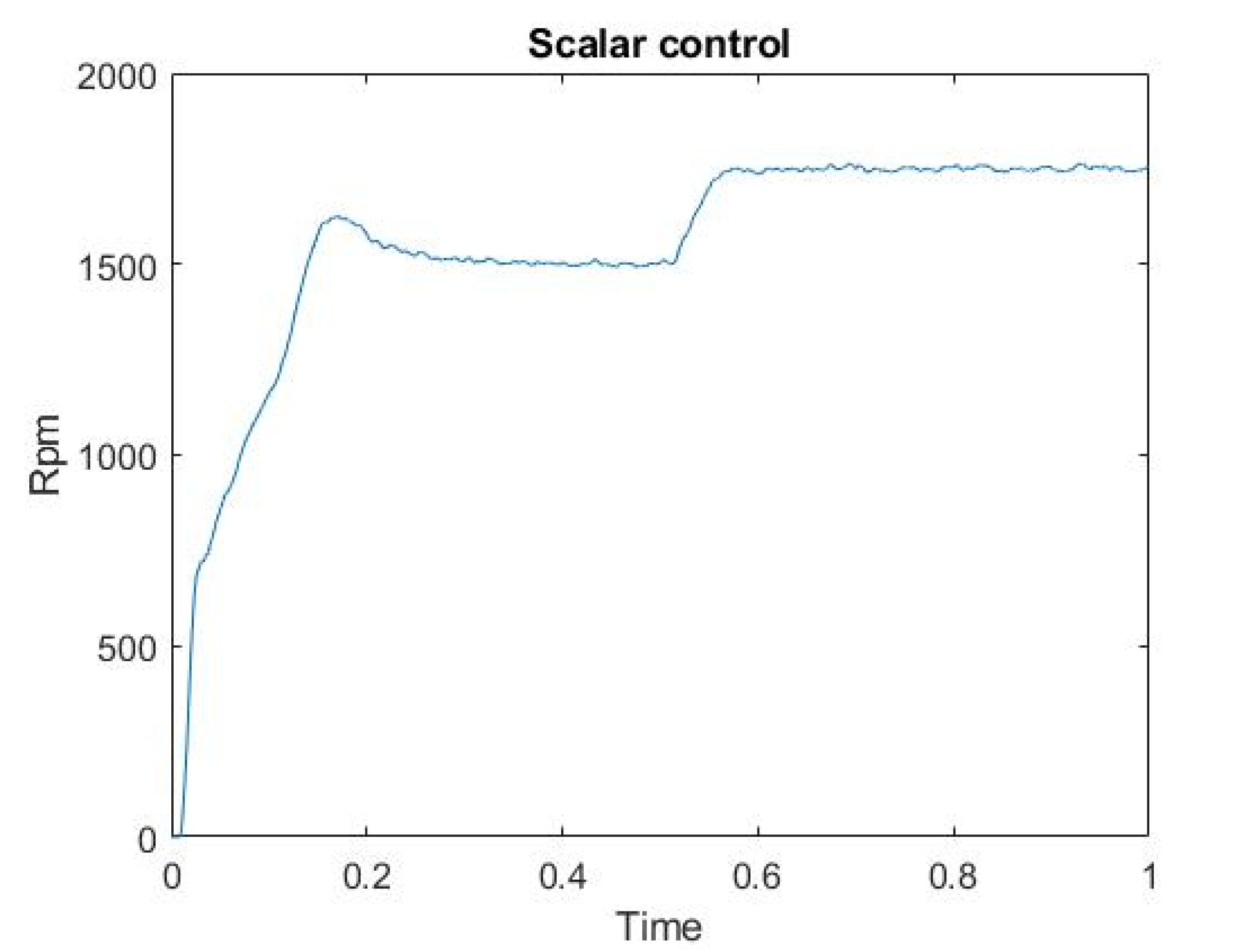
A simulation of the electric drive scalar control was also carried out. The speed was increased from the nominal value of 1500 rpm to 1750 rpm. The acceleration scope is shown in
Figure 19.
4. Conclusions
When supplying power to electric drives of conveyors in metallurgical and mining industries, which are located in areas remote from industrial networks, problems occur when starting this electric drive due to losses on a long line. The supply voltage can be up to 20% below the rated value, which significantly reduces the starting torque and prevents the electric motor from starting under load. It is therefore recommended to use an additional buffer power source developed on the basis of a supercapacitor unit.
The paper describes a mathematical model of an electric motor, a power source, developed simulation models of a frequency converter, a buffer power source. Based on these models, it was proved that it is not possible to start the electric motor under load in the case of a drawdown in the network. In addition, a solution to this problem is shown—the use of a buffer source of electricity based on a block of supercapacitors. The dynamic characteristics of the electric motor during discharging and charging of this unit are considered. It was proved that the use of this unit allows to compensate for losses in the electrical network and to start the electric motor under load.
An algorithm for the operation of the control system for the buffer power source was proposed. The results can be applied to the power supply of devices with EMF and active-inductive load, including for electric drives, batteries, and autonomous sources in automation devices.
The analysis of the simulations showed the correctness of the assumption about the use of a buffer power source and confirmed the possibility of using a block of Maxwell BMOD0058 E016 B02 supercapacitors, calculated for the buffer power supply of the motor AIR160S4. On conveyor lines in mining and metallurgy, where this motor is used, the developed system of a buffer power source can be used as an emergency power supply when starting an electric drive.
One direction, for further research, will be to try to use the energy generated during recuperation to recharge a supercapacitor based buffer energy source.


