Article

Research on Energy Transmission Mechanism of the Electro-Hydraulic Servo Pump Control System

1
School of Mechanical Engineering, Yanshan University, Qinhuangdao 066004, China
2
Mechanical and Electrical Engineering, Xinjiang Institute of Engineering, Urumqi 830023, China
*
Author to whom correspondence should be addressed.
Energies 2021, 14(16), 4869; https://doi.org/10.3390/en14164869
Submission received: 12 July 2021 / Revised: 3 August 2021 / Accepted: 6 August 2021 / Published: 10 August 2021

Abstract

:
The electro-hydraulic servo pump control system (EHSPCS) is a volume control system that uses a permanent magnet synchronous motor (PMSM) with a fixed displacement pump to directly drive and control the hydraulic cylinder. The energy transmission law of the system is very complicated due to the transformation of electrical, mechanical and hydraulic energy as well as other energy fields, and qualitative analysis of the energy transfer efficiency is difficult. Energy transfer analysis of the EHSPCS under different working conditions and loads is proposed in this paper. First, the energy flow transfer mechanism was analyzed, and the mathematical and energy transfer models of the key components of the system were established to explore the energy characteristic state transition rule. Second, a power bond diagram model was built, its state equation and state matrix were deduced, and a system simulation model was built. Finally, combined with the EHSPCS experimental platform, simulation experiments were carried out on the dynamic position following and steady-state position holding conditions of the system, and the variation rules of the power of each energy characteristic state and the system energy transfer efficiency under different loads were obtained. The research results provide a foundation for the study of power matching and energy-saving mechanism of the EHSPCS.

1. Introduction

The electro-hydraulic servo pump control system (EHSPCS) adjusts the flow and pressure output of a fixed displacement pump by changing the speed and torque of a permanent magnet synchronous motor (PMSM), so as to realize high-precision control of the position and force of the hydraulic cylinder. The introduction of electro-hydraulic servo pump control technology overcomes the inherent shortcomings of the traditional valve control system, such as poor anti-pollution ability and large equipment area [1,2,3]. With its power-by-wire, high power–weight ratio, and environmentally friendly advantages [4,5,6], the EHSPCS is widely used in aircraft rudder surface control [7], marine steam turbine intake regulation [8], wind power variable paddle control [9], and other areas of high-precision control. The EHSPCS is a multi-energy field coupling control system. The dynamic evolution characteristics of energy conversion among the PMSM, fixed displacement pump, and hydraulic cylinder are very complex. In order to improve the efficiency of the system, research on the energy transmission mechanism of the EHSPCS becomes very important.
Aiming to investigate the energy conversion problem of the EHSPCS, experts and scholars have studied system thermodynamics theory based on energy dissipation [10], summarized the influence law of the system leakage coefficient on its working efficiency under the action of oil temperature, and optimized the system power model by adding boundary control conditions [11]. An energy-saving method of energy matching and load matching of motor-pump units was proposed with the goal of attaining optimal energy regulation [12,13]. In the study of [14], direct pressure feedback and adaptive displacement and pressure electro-hydraulic actuators were proposed, and it was verified that the latter was effective at reducing motor consumption. Another study [15] found that the mismatch between the load characteristics and the driving mode was the main reason for the low efficiency of large- and medium-sized hydraulic presses. In the study of [16], the power loss of the traditional airborne hydraulic actuator and the electro-hydrostatic actuator were analyzed based on the method of energy transfer under different working conditions. Aiming at investigating the energy dissipation of the mobile hydraulic system, a novel energy-saving system was presented in [17], in which the compensator was designed as a regeneration device consisting of a hydraulic motor and an electric generator. A hybrid electro-hydraulic elevator driving system was presented in [18], which can regenerate energy and improve safety. An analytical approach for time coordination between multi-axis servo drives was presented in [19] in order to maximally exploit the regenerative energy. A pseudo bond graph model of a thermo-hydraulic system was designed in [20] with 20-sim software, highlighting thermal and hydraulic transfer. The energy transfer characteristics of a direct drive volume control electro-hydraulic servo system with long pipeline and hydraulic winch test bench were studied in [21,22] by using a power bond diagram.
The above results studied the energy transfer characteristics of specific components of the hydraulic system, analyzed the mismatch between the drive and the load and the effect of oil temperature as the reasons for the low efficiency of the system, and proposed the control strategy and energy-saving system to reduce the energy loss, but lack of research on the energy transfer, transformation, storage and distribution of the entire EHSPCS. The transfer efficiency of each energy conversion element in the system under different load conditions is not considered. This paper takes EHSPCS as the research object, the energy flow conversion characteristics among the PMSM, fixed displacement pump, and hydraulic cylinder were analyzed and the energy transfer model of the system was established. The system simulation model was established by using a power bond diagram, and the energy transfer law under the two operating conditions of dynamic position following and steady-state position holding was studied on the simulated experimental platform, and the energy transfer efficiency of the EHSPCS was obtained.

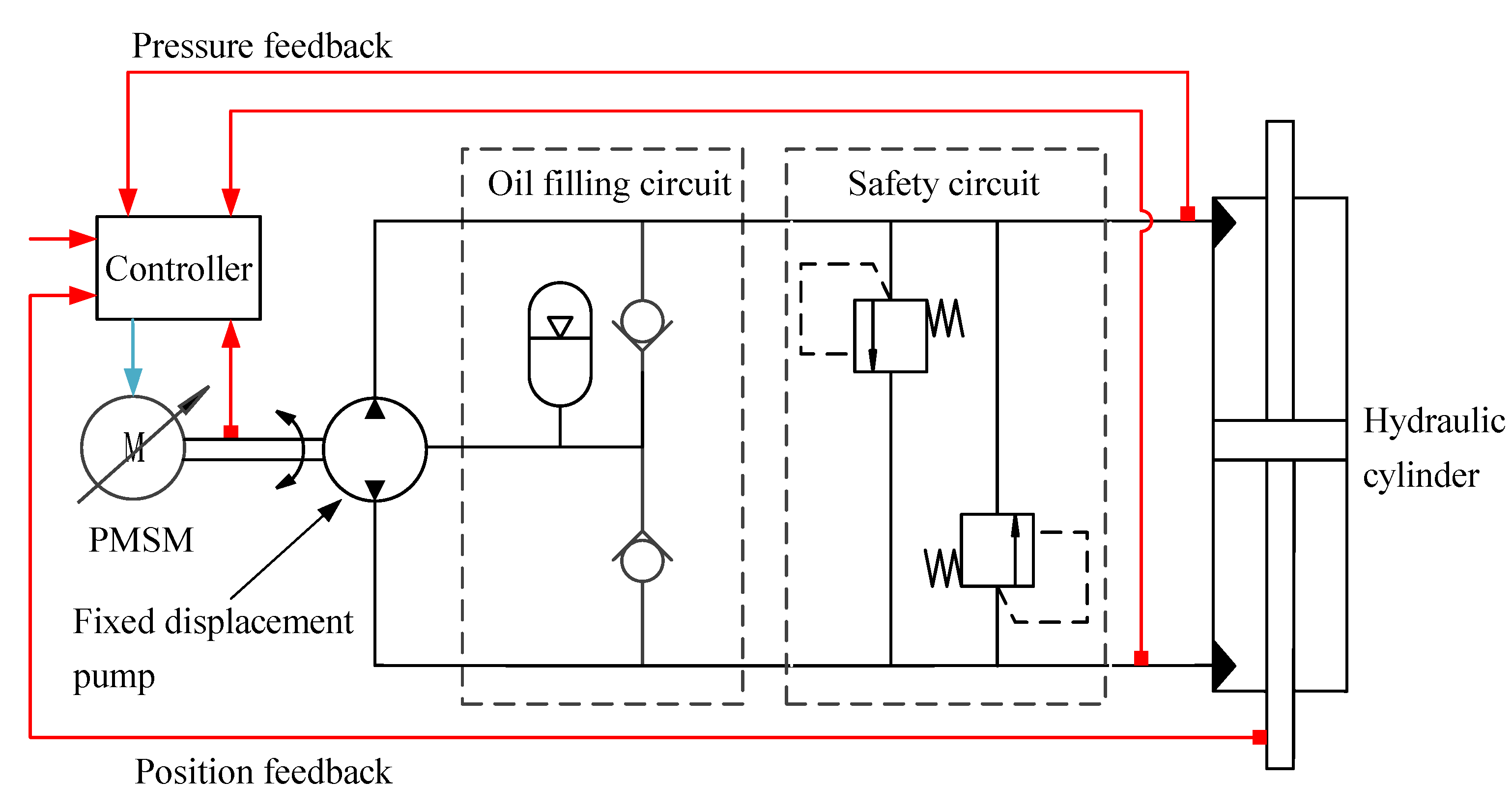
2. Working Principle of the EHSPCS

In the EHSPCS, the PMSM coaxially drives the fixed displacement pump, and the oil suction and oil pressure ports of the fixed displacement pump communicate with the load chamber of the hydraulic cylinder. The controller collects the position and pressure signals fed back by the hydraulic cylinder, makes a comparison and analysis with the input signals, and outputs the speed and torque instructions to the PMSM to realize high-precision control of the position and force of the cylinder. The oil-filling circuit is used to compensate the leakage loss of the system, and the safety circuit ensures that the system works within the safe pressure range. The hydraulic circuit of the EHSPCS is shown in Figure 1.

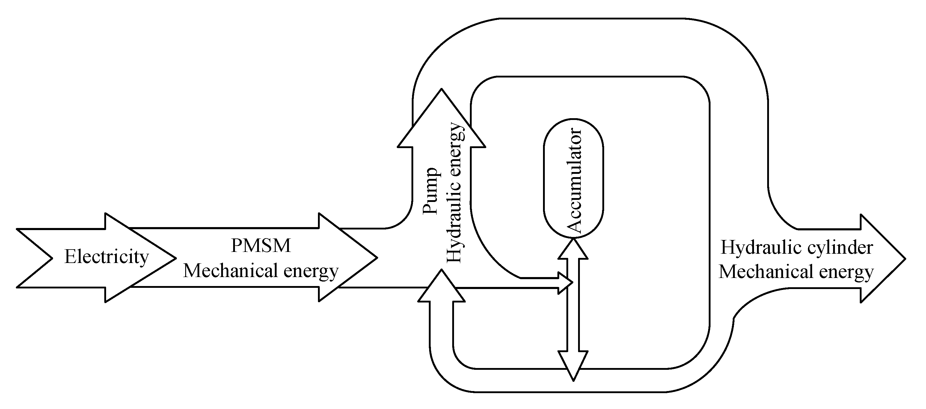
3. Establishment of Energy Transfer Model for EHSPCS System

Figure 2 shows the energy flow diagram of the EHSPCS. The PMSM is connected to the power grid, and the electric energy of the power grid is converted into the rotating mechanical energy of PMSM itself. The PMSM is coaxially connected to the fixed displacement pump and drives it to work. The fixed displacement pump compacts the oil from the low-pressure chamber into high-pressure oil to realize the conversion of mechanical energy to hydraulic energy. The oil leaked in the fixed displacement pump is stored in the accumulator to compensate the leakage of the system. The hydraulic cylinder converts the input pressure energy into the mechanical energy of the cylinder rod movement and drives the load connected with it to do work.
In order to study the energy transfer law of the EHSPCS, the key components of the system—the PMSM, the fixed displacement pump, and the hydraulic cylinder—should be analyzed by a mathematical model.

3.1. Mathematical Model of Key Components of the EHSPCS
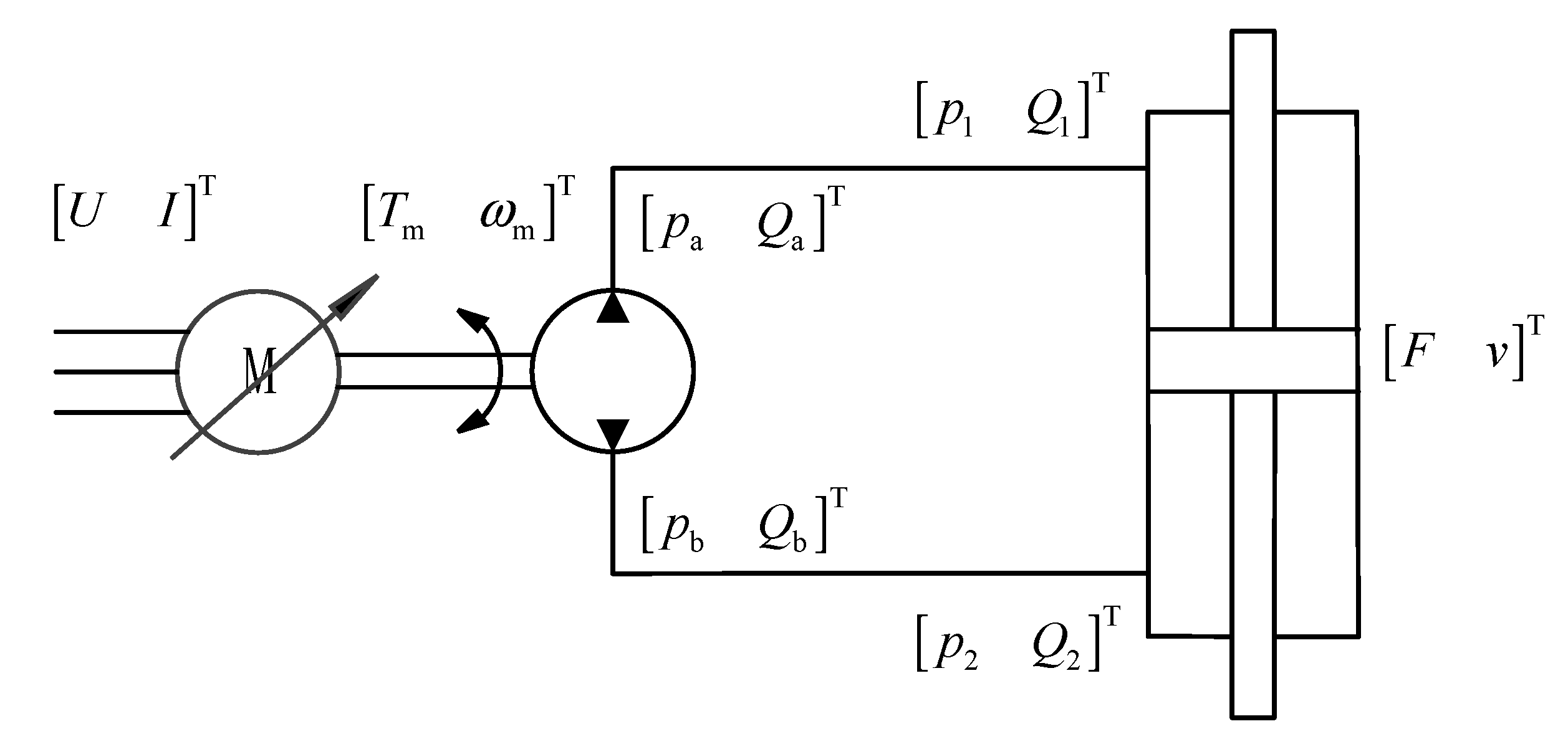
3.1.1. PMSM Model

As a power source, the PMSM absorbs energy from the power supply line at a certain rate and converts electrical power into mechanical power to drive the fixed displacement pump. The voltage equation of the PMSM can be expressed as:
{ U d = R s i d + L d d d t i d ω e L q i q U q = R s i q + L q d d t i q + ω e ( L d i d + ψ f )
The control methods of PMSM include vector control, direct torque control and decoupling control. Most of them use id = 0 vector control technology. The equivalent armature circuit voltage equation of PMSM using id = 0 control strategy can be expressed as:
U q = L q d d t i q + R s i q + K e p ω m
The motion equation of the PMSM can be expressed as:
T m B m ω m T L = J m d ω m d t
Laplace change of Equations (2) and (3) can be expressed as:
U K e p ω m = ( L q s + R s ) I
T m T L = ( J m s + B m ) ω m

3.1.2. Fixed Displacement Pump Model

The hydraulic pump is the power source of hydraulic transmission. When the motor drives the fixed displacement pump to rotate, the low-pressure liquid energy is absorbed and the high-pressure liquid of certain pressure and flow is conveyed to the hydraulic system. The flow continuity equation of the fixed displacement pump can be expressed as:
Q a = D p ω p k ip ( p a p b ) k ep ( p a p 0 )
The torque balance equation of the fixed displacement pump can be expressed as:
T L + D p p b D p p a B p ω p = J p d ω p d t
The Laplace transform of Equation (7) can be expressed as:
T L + D p p b D p p a = ( J p s + B p ) ω p

3.1.3. Hydraulic Cylinder Model

The hydraulic cylinder belongs to the energy conversion element of the actuator, which can convert hydraulic energy into mechanical energy and drive the load to realize linear motion. The external leakage of the hydraulic cylinder is ignored, and the flow continuity equation can be expressed as:
Q 1 = A v + k c ( p 1 p 2 )
The force balance equation of the hydraulic cylinder can be expressed as:
p 1 A p 2 A B v F = M d v d t
The Laplace transform of Equation (10) can be expressed as:
p 1 A p 2 A F = ( M s + B ) v

3.2. Mathematical Model of the EHSPCS Energy Transfer

In the process of analyzing the energy transfer of the system, the electrical energy input is taken as the source of energy transmission, then the PMSM, fixed displacement pump, and hydraulic cylinder are the basic conversion units of energy transfer. By analyzing the energy characteristic states of the input and output ends, the energy transfer model of the unit can be obtained. The energy transfer state of the system is shown in Figure 3.
(1)
The PMSM transforms the electric energy characteristic state vector [U I]T into the mechanical energy characteristic state vector [Tm ωm]T. According to Equations (4) and (5), the PMSM energy transfer model can be expressed as:
[ T m ω m ] = [ B m + J m s K e p ( B m + J m s ) ( L q s + R s ) K e p 1 K e p L q s + R s K e p ] [ U I ] + [ T L 0 ]
(2)
The fixed displacement pump transforms the mechanical energy characteristic state vector [Tm ωp]T into the hydraulic energy characteristic state vector [pa Qa]T. According to Equations (6) and (8), the energy transfer model of the fixed displacement pump can be expressed as:
[ p a Q a ] = [ 1 D p B p + J p s D p k ip + k ep D p D p + ( k ip + k ep ) ( B p + J p s ) D p ] [ T L ω p ] + [ p b k ep ( p 0 p b ) ]
(3)
The hydraulic cylinder transforms the hydraulic energy characteristic state vector [p1 Q1]T into the mechanical energy characteristic state vector [F v]T, and then drives the load to do work. According to Equations (9) and (11), the energy transfer model of the hydraulic cylinder can be expressed as:
[ F v ] = [ A + k c ( B + M s ) A B + M s A k c A 1 A ] [ p 1 Q 1 ] p 2 [ A + k c ( B + M s ) A k c A ]
Equations (12)–(14) qualitatively describe the energy characteristic state transition laws of the PMSM, the fixed displacement pump, and the hydraulic cylinder, respectively, providing a foundation for the establishment of the power bond diagram model and the study of the energy transfer efficiency of the EHSPCS.

3.3. Controller Model of the EHSPCS

As EHSPCS adopts the concept of volumetric speed regulation under the mechanism of PMSM-driven fixed displacement pump, the system dynamic characteristics such as low-speed stability and low-frequency response in the closed-loop position control process directly affect the high precision control of the system. Therefore, this study uses a fuzzy equivalent sliding mode variable structure control algorithm to realize the high precision control of the EHSPCS position [8]. The control architecture of sliding mode variable structure is shown in Figure 4.

4. Establishment of the EHSPCS Power Bond Diagram Simulation Model

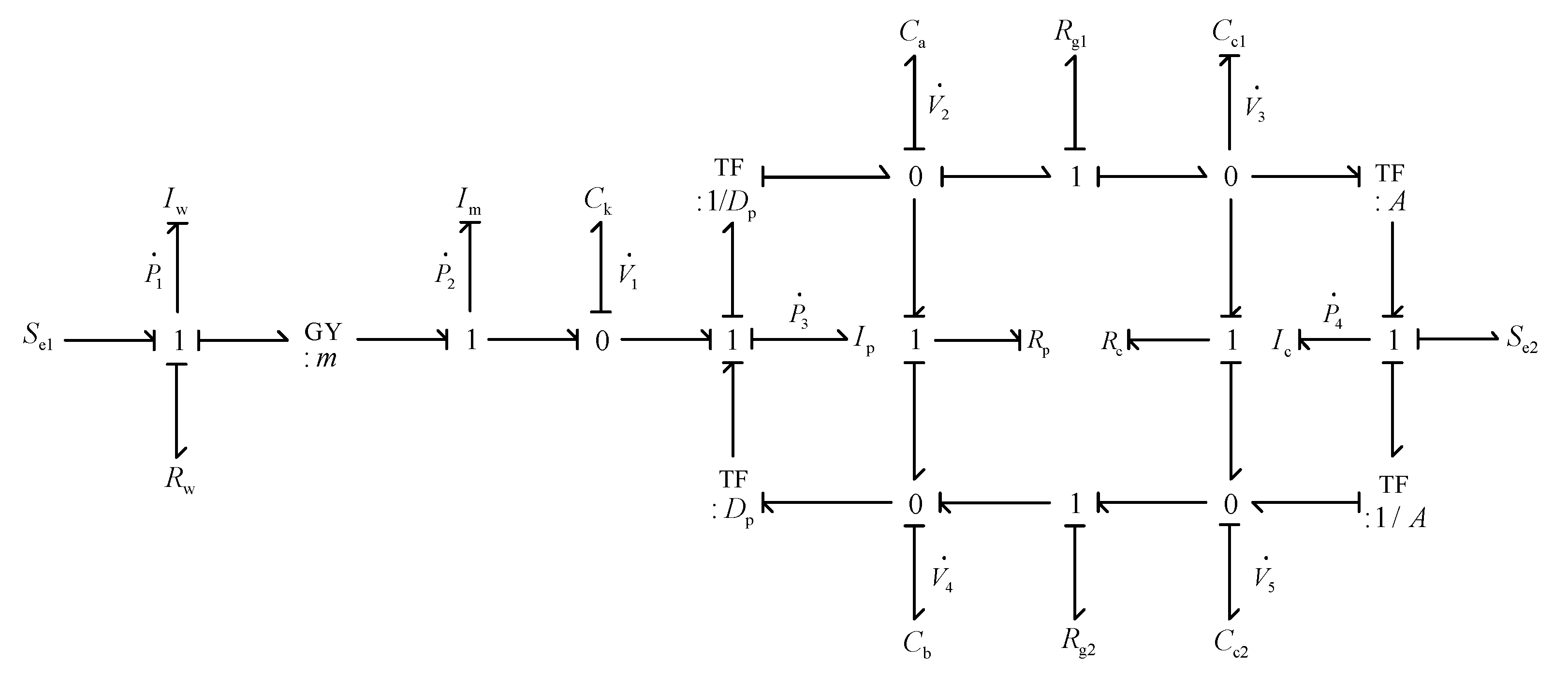
4.1. Power Bond Graph Model of the EHSPCS

The EHSPCS is a multi-energy characteristic state hydraulic system including electric, mechanical, and hydraulic energy. Some minor factors are ignored in the modeling, and only the main factors affecting the system power are considered. Assumptions are as follows:
(1)
The friction loss generated by the motor, the hydraulic pump, and the hydraulic cylinder in the process of movement and the fluid inductance of the valve block channel and the fluid resistance of the check valve are ignored.
(2)
The liquid capacity of the high-pressure channel and the high-pressure chamber of the fixed displacement pump is regarded as having the same liquid capacity value Ca, and the liquid capacity of the low-pressure channel, accumulator, and low-pressure chamber of the fixed displacement pump is regarded as having the same liquid capacity value Cb.
(3)
The density, viscosity, and bulk elastic modulus of the oil are ideal and regarded as constant values.
Figure 5 shows the model of the system established by using a power bond graph. The basic elements that constitute the graph are the bond graph elements (Ip, Ca, Rp, etc., in Figure 5). The lines between the bond graph elements represent the bond, and the half-arrow direction on the bond represents the direction of the power flow. In the diagram, the potential junction (0 junction) indicates that the potentials of bonds connected with it are equal, and the algebraic sum of the flows is zero. The co-current junction (1 junction) indicates that the flows on bonds connected to it are equal, and the algebraic sum of the potential is zero. The converter, TF, and the rotator, GY, represent the transformation relationship between the system energy in different characteristic states [23,24].
The power flow in Figure 5 is from left to right. The grid supplies the determined voltage Se1 to the first node, which includes the armature resistance Rw and the armature inductance Iw of the motor. The output power is converted into mechanical energy through the rotator GY. The second and third nodes contain the inertia of the motor rotor Im and the compliance of the motor shaft Ck. The output power is used to drive the rotation of the fixed displacement pump, and there is torque loss caused by the inertia of the rotor Ip and leakage loss caused by leakage fluid resistance Rp in the process of rotation. The output power of the fixed displacement pump is converted into hydraulic energy through the converter TF. High- and low-pressure chamber liquid capacity Ca and Cb and channel liquid resistance Rg1 and Rg2 are between the fixed displacement pump and the hydraulic cylinder. Liquid capacity Cc1 and Cc2 are in the two load chambers of the hydraulic cylinder, which are used to control the compression of oil. Leakage resistance RC in the hydraulic cylinder is used to control the leakage amount. The hydraulic cylinder converts the input power into mechanical energy through the converter. While driving the load Se2, it also needs to overcome the inertia force brought by the equivalent mass Ic on the cylinder rod.

4.2. State Equation and State Matrix of the EHSPCS

The system state equation is a system of first-order differential equations, and its variables have derivative relations. In the bond diagram, only the inertial element I and the capacitive element C have a calculus relationship, and the integral of the independent variables can be taken as the state variable. Here, generalized displacement or generalized volume V of capacitive element C and generalized momentum P of inertial element I are taken as the state variables of the system, where V1 is the angular displacement of the motor shaft rotation, V2 is the volume compression of oil in the high-pressure cavity of the fixed displacement pump and high-pressure channel, and V3 is the volume compression of oil in the oil inlet cavity of the hydraulic cylinder. V4 is the volume compression of oil in the low-pressure chamber of the fixed displacement pump, low-pressure channel, and accumulator, and V5 is the volume compression of oil in the oil discharge chamber of the hydraulic cylinder. P1 represents the magnetic flux of the motor, and P2, P3, and P4 represent the momentum of the motor, the fixed displacement pump, and the hydraulic cylinder, respectively. V 1 · , V 2 · , V 3 · , V 4 · , V 5 · , P 1 · , P 2 · , P 3 · , and P 4 · respectively represent the derivatives of the corresponding variables with respect to time. The state equations are obtained according to the relationship between the state variables and the bond graph elements in the power bond diagram of the system.
{ P 1 · = S e 1 P 1 R w I w P 2 m I m P 2 · = P 1 m I w V 1 C k V 1 · = P 2 I m P 3 I p P 3 · = V 1 C k + V 4 D p C b V 2 D p C a V 2 · = P 3 D p I p V 2 C a R g 1 + V 3 C c 1 R g 1 V 2 C a R p + V 4 C b R p V 3 · = V 2 C a R g 1 V 3 C c 1 R g 1 P 4 A I c V 3 C c 1 R c + V 5 C c 2 R c P 4 · = V 3 A C c 1 V 5 A C c 2 S e 2 V 4 · = V 5 C c 2 R g 2 V 4 C b R g 2 + V 2 C a R p V 4 C b R p P 3 D p I p V 5 · = P 4 A I c + V 3 C c 1 R c V 5 C c 2 R c V 5 C c 2 R g 2 + V 4 C b R g 2
The EHSPCS is a two-input, single-output system. The input variable can be expressed as: U(t) = [Se1 Se2]T, and the output variable can be expressed as: Y(t) = [v]. The system consists of nine energy transfer elements, and the corresponding state variable can be expressed as: X(t) = [P1 P2 V1 P3 V2 V3 P4 V4 V5]T. The state–space expression of the system can be expressed as:
{ X ( t ) · = A ( t ) X ( t ) + B ( t ) U ( t ) Y ( t ) · = C ( t ) X ( t ) + D ( t ) U ( t )
In addition, the state matrix A(t), the input matrix B(t), the output matrix C(t), and the direct linking matrix D(t) can be expressed as:
A ( t ) = [ R w I w m I m 0 0 0 0 0 0 0 m I w 0 1 C k 0 0 0 0 0 0 0 1 I m 0 1 I p 0 0 0 0 0 0 0 1 C k 0 D p C a 0 0 D p C b 0 0 0 0 D p I p R g 1 + R p C a R g 1 R p 1 C c 1 R g 1 0 1 C b R p 0 0 0 0 0 1 C a R g 1 R c + R g 1 C c 1 R g 1 R c A I c 0 1 C c 2 R c 0 0 0 0 0 A C c 1 0 0 A C c 2 0 0 0 D p I p 1 C a R p 0 0 R p + R g 2 C b R g 2 1 C c 2 R g 2 0 0 0 0 0 1 C c 1 R c A I c 1 C b R g 2 R g 2 + R c C c 2 R c ]
B ( t ) = [ 1 0 0 0 0 0 0 0 0 0 0 0 0 0 0 1 0 0 ] T
C ( t ) = [ 0 0 0 0 0 0 1 I c 0 0 ]
D ( t ) = 0

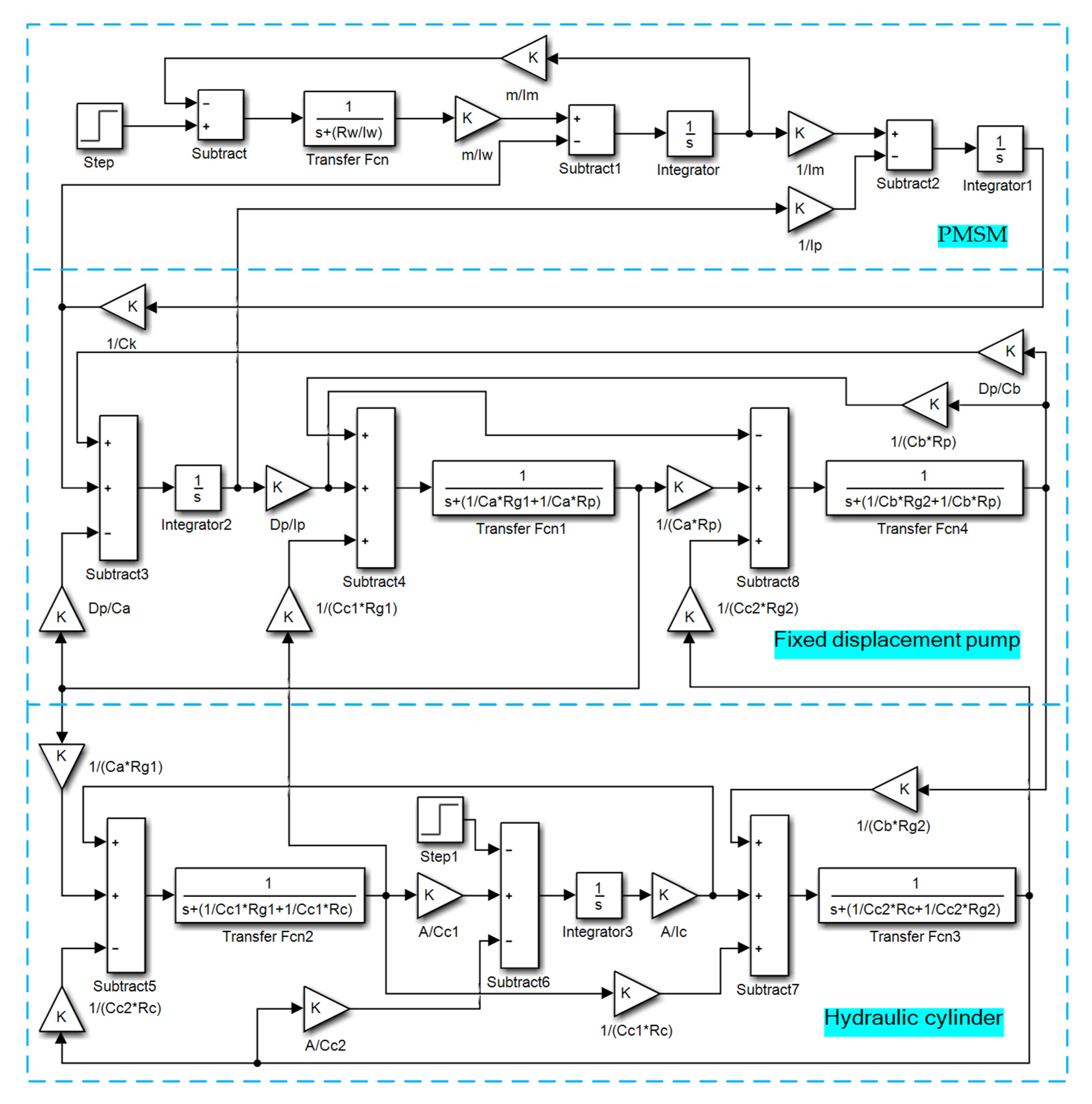
4.3. Simulink Simulation Model of the EHSPCS

According to the bond diagram model and state equation of the EHSPCS, the simulation model is established after connecting the four parts of the PMSM, the hydraulic pump, the hole, and the hydraulic cylinder, as shown in Figure 6.
System simulation parameters are shown in Table 1.

5. Energy Transfer Simulation Experiment of the EHSPCS

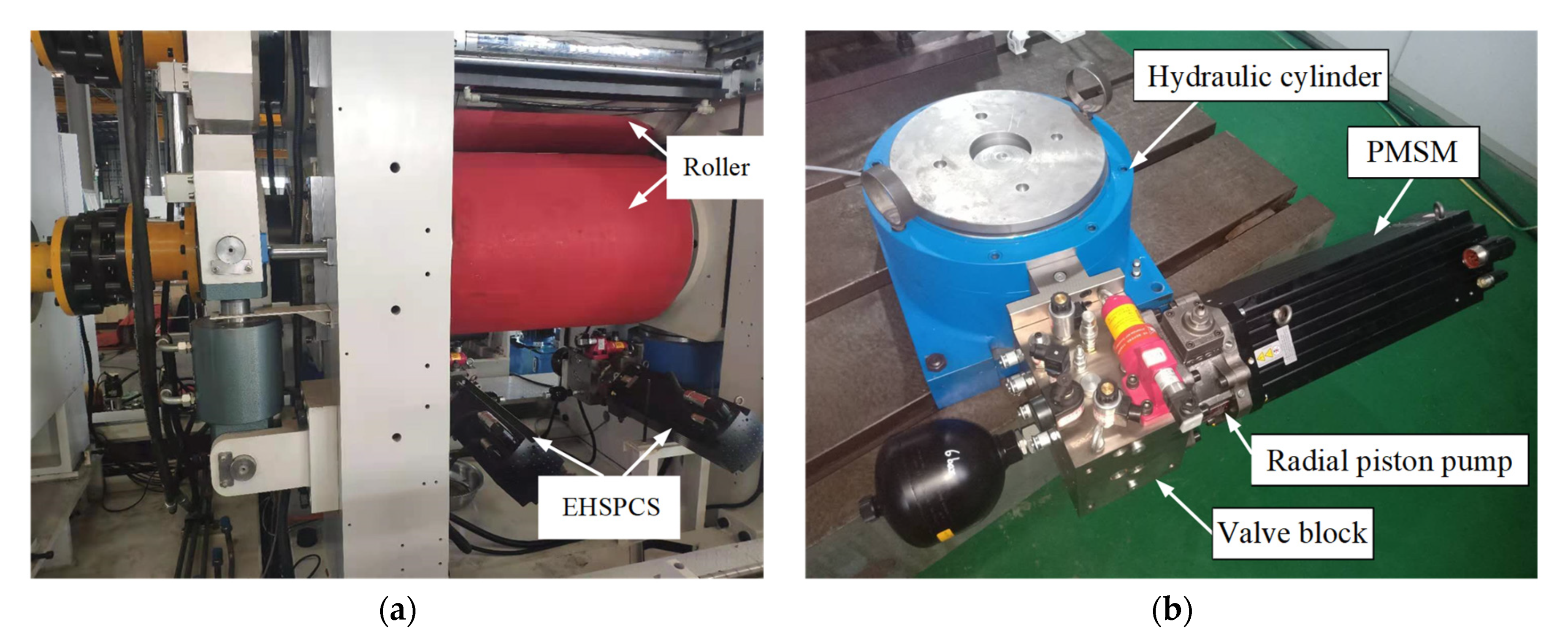
5.1. Experimental Platform for Energy Transfer Research of the EHSPCS

In the process of studying the energy transfer mechanism of the EHSPCS, a combination of simulation and experimental platform is adopted, and a lithium battery rolling machine is used as the experimental platform, as shown in Figure 7. The rolling mill takes advantage of the friction between rollers and the battery pole piece to pull it into the rotating rollers. The distance between the two rollers is controlled by the EHSPCS to compress the pole piece to the target thickness.
During the operation of the PMSM, the driver can collect the operating parameters of the motor in real time, such as the voltage and current input to the motor, the speed and torque output of the motor. The driver feeds these parameters back to the computer and generates corresponding curves in the software. A pressure sensor and a flow sensor are installed in the valve block to collect the pressure and flow of the system. The hydraulic cylinder is equipped with a built-in displacement sensor and a force sensor to collect the speed and force of the hydraulic cylinder. The sensor feeds these physical quantities back to the computer through the controller and generates curves in the software.

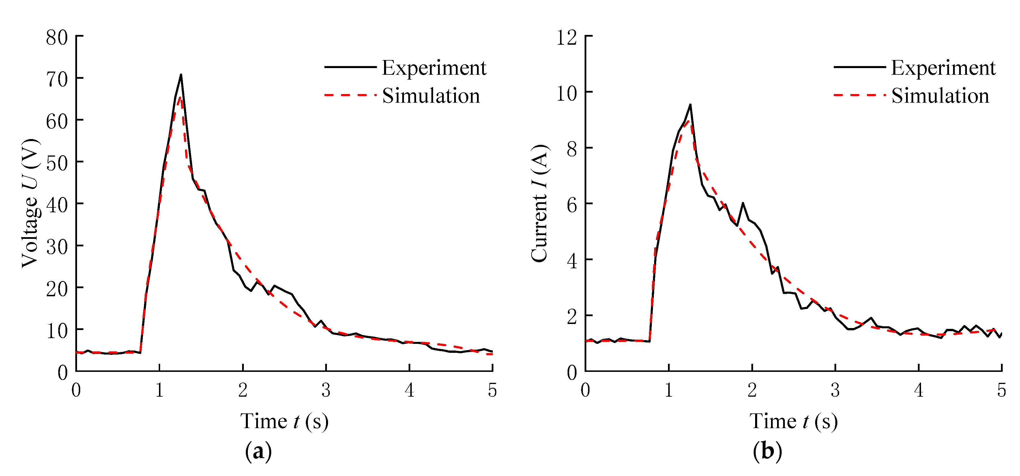
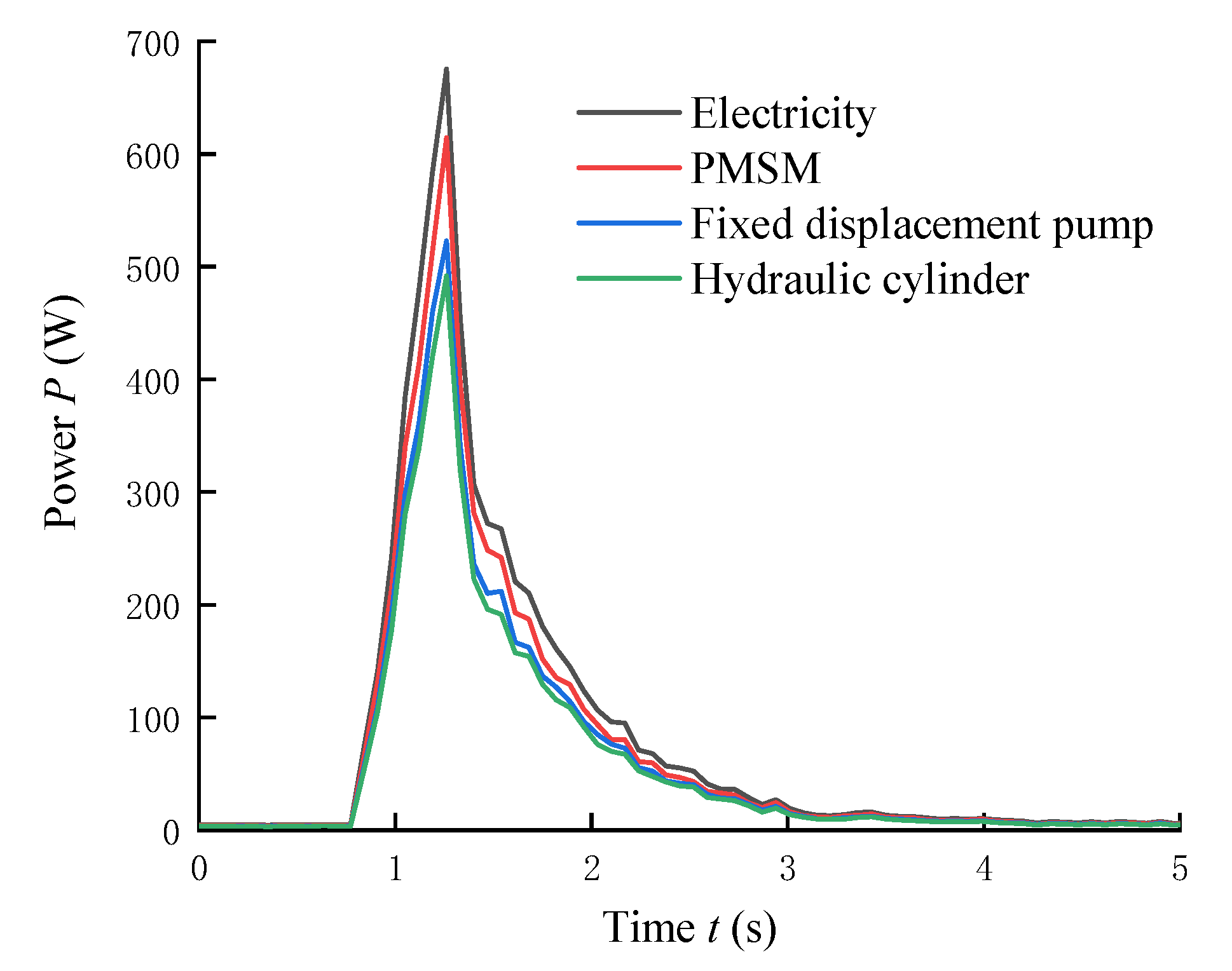
5.2. Energy Transfer Analysis of the Dynamic Position Following Process

When the EHSPCS is working in position control mode, when a new position instruction is input, the controller will plan the PMSM speed output value according to the deviation between input and actual values, so that the cylinder rod can quickly respond to the specified position. In this section, the variation rule of each component’s output characteristic parameter with time in the process of system position change is analyzed, and the energy transfer efficiency between elements is obtained.
In the process of simulation and experiment, the system works in the initial position for the first 0.75 s, when a new position instruction is given, which is 3 mm higher than the original position. The simulation and experimental comparison curves of the output parameters of each component of the system over time are shown in Figure 8.
It can be seen from Figure 8 that the simulation and experimental curves of PMSM speed, fixed displacement pump flow and hydraulic cylinder speed basically coincide. However, after partial amplification, the experimental and simulation curves are still slightly different. The main reasons for this difference include the low-speed flow pulsation of the hydraulic pump, the time-varying nonlinearity of the load, and the measurement error of the sensor. The variation trends of voltage, current, speed, flow, and speed of the system are basically the same and the initial position is basically unchanged; when a new position instruction is input, the state values show a sharp increase, and then slowly decline. The change trends of torque, pressure, and output force of the system are basically the same, and the initial position is basically unchanged; when a new position instruction is input, all state values show a steep increase, and then the change rule of step-down appears.
In order to more intuitively study the EHSPCS energy transfer law in more detail, the output power of each part of the power grid, PMSM, fixed displacement pump, and hydraulic cylinder and the proportion of each part of the energy output during the dynamic position following process of the system are obtained, as shown in Figure 9 and Figure 10, respectively.
As can be seen from Figure 9, the energy characteristic state values of the system are basically unchanged at the initial position. When the new position instruction is input, the state values increase sharply and then decrease slowly. In Figure 10, the electrical power input is set to 100%. During the experiment, the output power of the PMSM, the fixed displacement pump, and the hydraulic cylinder accounted for approximately 87.4, 77.7, and 72.6%, respectively, and the power loss accounted for approximately 12.6, 9.7, and 5.1%. That is, in the process of dynamic position following energy transfer, the PMSM power loss was the largest, followed by the fixed displacement pump; the hydraulic cylinder power loss was the smallest, and the total energy transfer efficiency of the system was about 72.6%.

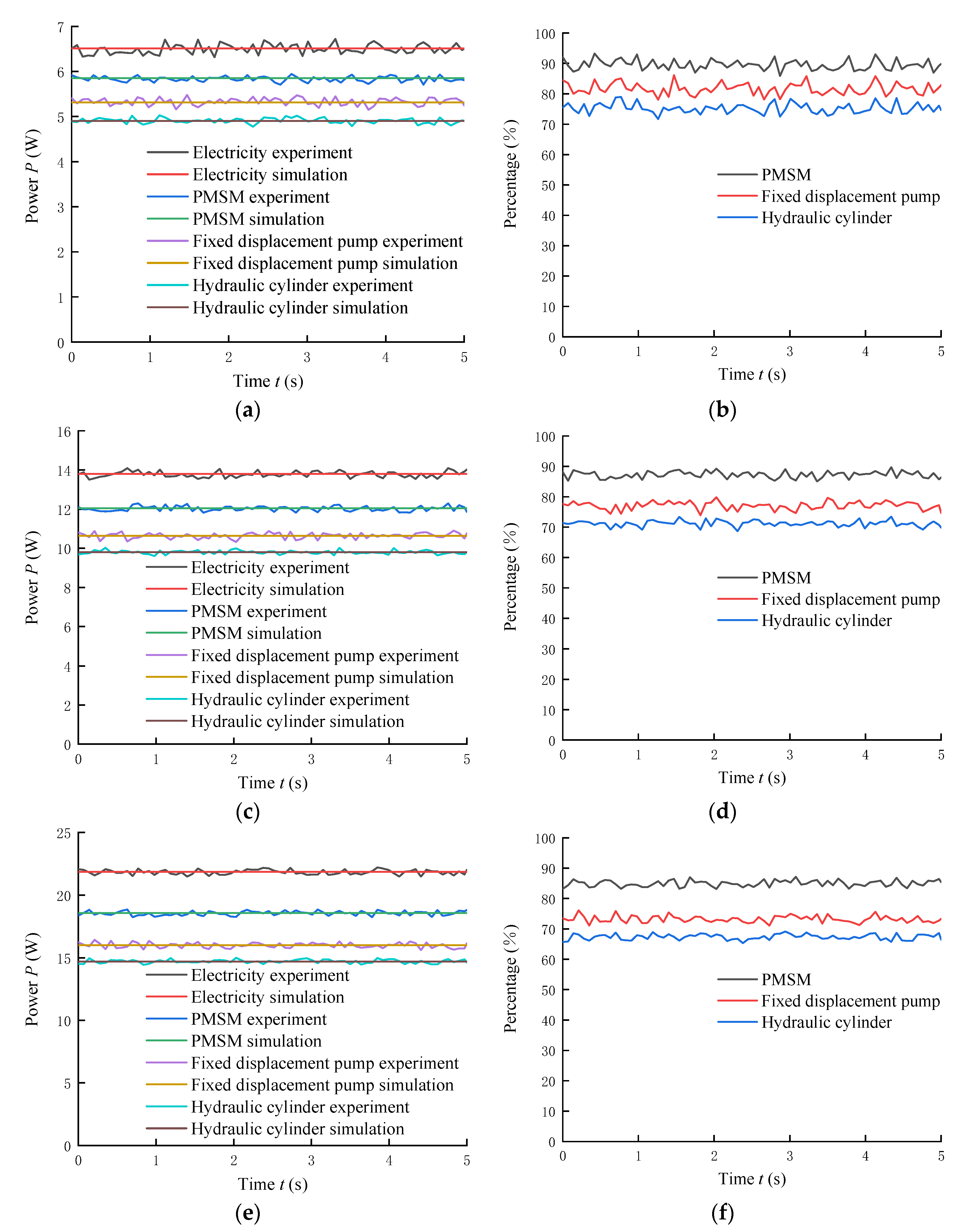
5.3. Energy Transfer Analysis of the Steady-State Position Holding Process

In the process of maintaining the steady-state position of the system, the external load force was kept constant at 70, 140, and 210 kN, respectively, and the simulation and experimental power comparison curves of the energy characteristic states of the system and the energy output ratio of the key components under different load forces were obtained. The curves are shown in Figure 11.
According to the simulation and experimental results of the three load conditions shown in Figure 11, it can be seen that the power curves of the energy characteristic states basically coincide. When the load force changes, the trend and fluctuation of the power curve remain basically unchanged, while the energy output ratio of the key components changes. There is a certain loss in the process of power transmission of the system under different loads, and the power gradually decreases along the direction of power transmission, during which the PMSM loses more power and the hydraulic cylinder loses less power. The power values and transfer efficiency of the parts of the system are shown in Table 2.
From the data in Table 2, it can be seen that when the external load force of the system increases, the power value of each energy state gradually increases and the transmission efficiency gradually decreases. The reason for this phenomenon is that the load determines the system pressure. When the load force increases, the system pressure will increase, which will lead to increased system flow and frictional resistance and reduced system efficiency.

6. Conclusions

In this paper, based on the energy transfer mathematical model, an EHSPCS power bond diagram model was established, and a simulation and experimental platform was built to carry out research on the two working conditions of dynamic position following and steady position holding of the system, and the energy transfer analysis method under different conditions and different loads was proposed. The results show that in the dynamic position following process, when the new position instruction is input, the energy state value increases sharply and then decreases slowly. In the process of energy transfer, the PMSM power loss is the largest, followed by the fixed displacement pump, and the hydraulic cylinder power loss is the smallest. The total energy transfer efficiency of the system is about 72.6%. In the steady-state position holding process, when the external load increases, the power value of energy state of the system gradually increases, and the increased system pressure increases the leakage flow and friction loss, which leads to a gradual decrease in transfer efficiency.

Author Contributions

Formal analysis, M.Y.; Funding acquisition, G.C. and G.Y.; Methodology, M.Y., J.L. and C.Y.; Project administration, G.Y., C.A. and Y.L.; Resources, M.Y. and G.C.; Software, J.L. and C.Y.; Supervision, G.C. and C.Y.; Validation, G.Y. and C.A.; Writing—original draft, M.Y.; Writing—review and editing, M.Y. and G.C. All authors have read and agreed to the published version of the manuscript.

Funding

This research was supported by the Key R&D Projects in Hebei Province (No. 20314402D), the Key Project of Science and Technology Research in Hebei Province (No. ZD2020166), the Key Project of Science and Technology Research in Hebei Province (No. ZD2021340), and the General Project of Natural Science Foundation in Xinjiang Uygur Autonomous Region (No. 2021D01A63).

Institutional Review Board Statement

Not applicable.

Informed Consent Statement

Not applicable.

Data Availability Statement

Not applicable.

Conflicts of Interest

The authors declare no conflict of interest.

Nomenclature

Ud/Uqd-q axis component of the stator voltage (V)
id/iqd-q axis components of the stator current (A)
Ld/Lqd-q axis components of the stator inductance (H)
RsStator resistance (Ω)
ωeElectrical angular velocity (rad/s)
ΨfPermanent magnet flux (H)
KeBack potential coefficient
pPole logarithm of the motor
ωmMechanical angular velocity of the motor (rad/s)
TmThe electromagnetic torque of the motor (Nm)
BmDamping coefficient of the motor (N/(m/s))
TLLoad torque (Nm)
JmMoment of inertia of the motor (kg·m2)
QaOutput flow of the fixed displacement pump (m3/s)
DpDisplacement of the fixed displacement pump (m3/rad)
ωpSpeed of the fixed displacement pump (rad/s)
kipInternal leakage coefficient of the fixed displacement pump (Pa/(m3/s))
kepExternal leakage coefficient of the fixed displacement pump (Pa/(m3/s))
paOutlet pressure of the fixed displacement pump (Pa)
pbInlet pressure of the fixed displacement pump (Pa)
p0Discharge chamber pressure of the fixed displacement pump (Pa)
BpViscous damping coefficient of the fixed displacement pump (N/(m/s))
JpMoment of inertia of the fixed displacement pump (kg·m2)
Q1Flow input to the hydraulic cylinder (m3/s)
AEffective action area of the hydraulic cylinder (m2)
vSpeed of the hydraulic cylinder (m/s)
kcInternal leakage coefficient of the hydraulic cylinder (Pa/(m3/s))
p1Pressure input to the hydraulic cylinder (Pa)
p2Output pressure of the hydraulic cylinder (Pa)
BViscous damping coefficient of oil (N/(m/s))
FExternal load of the hydraulic cylinder (N)
MTotal mass of piston rod and load (kg)

References

  1. Yan, G.; Jin, Z.; Yang, M.; Yao, B. The thermal balance temperature field of the electro-hydraulic servo pump control system. Energies 2021, 14, 1364. [Google Scholar] [CrossRef]
  2. Zhang, T.; Chen, G.; Yan, G.; Zhang, C.; Li, Y.; Ai, C. Research on the nonlinear characteristic of flow in the electro-hydraulic servo pump control system. Processes 2021, 9, 814. [Google Scholar] [CrossRef]
  3. Wang, Y.; Kou, G.; Hu, S. Thermal modeling and analysis of oil-cooled high speed permanent magnet motor in the EHA system. In Proceedings of the CSAA/IET International Conference on Aircraft Utility Systems (AUS 2018), Guiyang, China, 19–22 June 2018; pp. 710–715. [Google Scholar]
  4. Chakraborty, I.; Mavris, D.N.; Emeneth, M.; Schneegans, A. A methodology for vehicle and mission level comparison of more electric aircraft subsystem solutions: Application to the flight control actuation system. Proc. Inst. Mech. Eng. Part G J. Aerosp. Eng. 2015, 229, 1088–1102. [Google Scholar] [CrossRef]
  5. Alle, N.; Hiremath, S.S.; Makaram, S.; Subramaniam, K.; Talukdar, A. Review on electro hydrostatic actuator for flight control. Int. J. Fluid Power 2016, 17, 125–145. [Google Scholar] [CrossRef]
  6. Shi, C.; Wang, X.; Wang, S.; Wang, J.; Tomovic, M.M. Adaptive decoupling synchronous control of dissimilar redundant actuation system for large civil aircraft. Aerosp. Sci. Technol. 2015, 47, 114–124. [Google Scholar] [CrossRef]
  7. Yu, B.; Wu, S.; Jiao, Z.; Shang, Y. Multi-Objective Optimization Design of an Electrohydrostatic Actuator Based on a Particle Swarm Optimization Algorithm and an Analytic Hierarchy Process. Energies 2018, 11, 2426. [Google Scholar] [CrossRef] [Green Version]
  8. Yan, G.; Jin, Z.; Zhang, T.; Zhao, P. Position control study on pump-controlled servomotor for steam control valve. Processes 2021, 9, 221. [Google Scholar] [CrossRef]
  9. Nguyen, M.T.; Dang, T.D.; Ahn, K.K. Application of Electro-Hydraulic Actuator System to Control Continuously Variable Transmission in Wind Energy Converter. Energies 2019, 12, 2499. [Google Scholar] [CrossRef] [Green Version]
  10. Li, K.; Zhong, L.; Kun, L.; Ping, Y. Thermal-hydraulic Modeling and Simulation of the Hydraulic System based on the Electro-hydrostatic Actuator. Procedia Eng. 2014, 80, 272–281. [Google Scholar] [CrossRef] [Green Version]
  11. Keivan, B.; Mehdi, R.S.; Ali, T.H.; Mohammad, Z. An energy-saving nonlinear position control strategy for electro-hydraulic servo systems. ISA Trans. 2015, 59, 268–279. [Google Scholar]
  12. Qu, S.; Fassbender, D.; Vacca, A.; Busquets, E. A High-efficient solution for electro-hydraulic actuators with energy regeneration capability. Energy 2021, 216, 119291. [Google Scholar] [CrossRef]
  13. Dong, L.; Yan, H.; Feng, L.; Tan, Q. Modelling and performance analysis of designed energy-efficient EHA under gravity loads. Int. J. Model. Identif. Control 2018, 30, 253–260. [Google Scholar] [CrossRef]
  14. Li, D.; Li, Y.; Li, Y.; Zhang, P.; Dong, S.; Yang, L. Study on PMSM Power Consumption of Dual-Variable Electro-Hydraulic Actuator with Displacement-Pressure Regulation Pump. In Proceedings of the 2018 IEEE/ASME International Conference on Advanced Intelligent Mechatronics (AIM), Auckland, New Zealand, 9–12 July 2018; pp. 1172–1177. [Google Scholar]
  15. Zhao, K.; Liu, Z.; Yu, S.; Li, X.; Huang, H.; Li, B. Analytical energy dissipation in large and medium-sized hydraulic press. J. Clean. Prod. 2015, 103, 908–915. [Google Scholar] [CrossRef]
  16. Hu, W.; Zhou, L.; Tian, Y.; Jiao, Z.; Shang, Y.; Song, Z.; Yan, L. Analysis for the power loss of electro hydrostatic actuator and hydraulic actuator. In Proceedings of the 2015 IEEE International Conference on Advanced Intelligent Mechatronics (AIM), Busan, Korea, 7–11 July 2015; pp. 613–616. [Google Scholar]
  17. Wang, T.; Wang, Q. An energy-saving pressure-compensated hydraulic system with electrical approach. IEEE/ASME Trans. Mechatron. 2014, 19, 570–578. [Google Scholar] [CrossRef]
  18. Zhao, B.; Quan, Z.; Li, Y.; Quan, L.; Hao, Y.; Ding, L. A hybrid-driven elevator system with energy regeneration and safety enhancement. IEEE Trans. Ind. Electron. 2020, 67, 7715–7726. [Google Scholar] [CrossRef]
  19. Kaviani, A.K.; Hadley, B.; Mirafzal, B. A time-coordination approach for regenerative energy saving in multiaxis motor-drive systems. IEEE Trans. Power Electron. 2012, 27, 931–941. [Google Scholar] [CrossRef]
  20. Aridhi, E.; Abbes, M.; Mami, A. Pseudo bond graph model of a thermo-hydraulic system. In Proceedings of the 2013 5th International Conference on Modeling, Simulation and Applied Optimization (ICMSAO), Hammamet, Tunisia, 28–30 April 2013; pp. 1–5. [Google Scholar]
  21. Cheng, L.; Ye, Z.; Tong, Z. Bond graph modeling and simulation analysis of direct drive volume control electro-hydraulic servo system with long pipeline. In Proceedings of the 2016 IEEE International Conference on Aircraft Utility Systems (AUS), Beijing, China, 10–12 October 2016; pp. 309–312. [Google Scholar]
  22. Li, M.; Xu, B.; Chen, Z. Bond graph model of a new hydraulic winch test bench on energy recycle. In Proceedings of the 2010 IEEE International Conference on Industrial Engineering and Engineering Management, Macao, China, 7–10 December 2010; pp. 808–812. [Google Scholar]
  23. Rodríguez-Guillén, J.; Salas-Cabrera, R.; García-Vite, P.M. Bond graph as a formal methodology for obtaining a wind turbine drive train model in the per-unit system. Int. J. Electr. Power Energy Syst. 2021, 124, 106382. [Google Scholar] [CrossRef]
  24. Yu, L.; Qi, X. Bond-graph modeling in system engineering. In Proceedings of the 2012 International Conference on Systems and Informatics (ICSAI2012), Yantai, China, 19–20 May 2012; pp. 376–379. [Google Scholar]
Figure 1. Hydraulic circuit of electro-hydraulic servo pump control system (EHSPCS).
Energies 14 04869 g001
Figure 2. Schematic diagram of the EHSPCS energy flow.
Energies 14 04869 g002
Figure 3. EHSPCS energy transfer state diagram.
Energies 14 04869 g003
Figure 4. Sliding mode variable structure control architecture of the EHSPCS.
Energies 14 04869 g004
Figure 5. EHSPCS power bond graph model.
Energies 14 04869 g005
Figure 6. Simulink simulation model of the EHSPCS.
Energies 14 04869 g006
Figure 7. Experimental platform for energy transfer research of the EHSPCS: (a) Lithium battery rolling machine; (b) EHSPCS unit; (c) Power cabinet.
Energies 14 04869 g007aEnergies 14 04869 g007b
Figure 8. Energy transfer simulation and experimental curves of the EHSPCS: (a) Input voltage; (b) Input current; (c) PMSM speed; (d) PMSM torque; (e) Flow of fixed displacement pump; (f) Pressure of fixed displacement pump; (g) Hydraulic cylinder speed; (h) Output force of hydraulic cylinder.
Energies 14 04869 g008aEnergies 14 04869 g008b
Figure 9. Experimental power curve of key components.
Energies 14 04869 g009
Figure 10. Energy output ratio of key components.
Energies 14 04869 g010
Figure 11. Simulation and experimental power comparison curves and energy output ratio curves of key components of the system under different load forces: (a) Power comparison curve under 70 kN load; (b) Energy output ratio curve under 70 kN load; (c) Power comparison curve under 140 kN load; (d) Energy output ratio curve under 140 kN load; (e) Power comparison curve under 210 kN load; (f) Energy output ratio curve under 210 kN load.
Energies 14 04869 g011
Table 1. Simulation parameters of the electro-hydraulic servo pump control system (EHSPCS).
ParametersValue
Input voltage (V)380
Armature inductance of PMSM (H)0.0025
Armature resistance of PMSM (Ω)1.5
Armature coefficient of PMSM ((N·m)/A)0.2
Rotor inertia of PMSM (kg·m2)0.0063
Compliance of PMSM shaft (rad/N·m) 9.75 × 10 10
Rotor inertia of fixed displacement pump (kg·m2) 2 × 10 3
Displacement of fixed displacement pump (m3/rad) 3 × 10 6
Liquid capacity of high-pressure channel and high-pressure chamber of fixed displacement pump (m3/Pa) 6.95 × 10 14
Leakage fluid resistance of fixed displacement pump (Pa/(m3/s)) 1.98 × 10 8
Fluid resistance of high-pressure channel (Pa/(m3/s)) 9.17 × 10 6
Liquid volume of high-pressure chamber of hydraulic cylinder (m3/Pa) 8.97 × 10 14
Internal leakage resistance of hydraulic cylinder (Pa/(m3/s)) 5 × 10 11
Effective area of hydraulic cylinder (m2) 1.256 × 10 3
Equivalent mass on piston of hydraulic cylinder (kg)150
Liquid volume of low-pressure chamber of hydraulic cylinder (m3/Pa) 8.97 × 10 14
Fluid resistance of low-pressure channel (Pa/(m3/s)) 9.17 × 10 6
Liquid capacity of low-pressure channel, accumulator, and low-pressure chamber of fixed displacement pump (m3/Pa) 6.95 × 10 14
Table 2. Power values and transfer efficiency of energy states under different load forces.
External Load Force (kN)Electric Power (W)PMSM Power (W)Fixed Displacement Pump Power (W)Hydraulic Cylinder Power (W)Efficiency (%)
706.515.845.314.9075.27
14013.8012.0510.639.8071.01
21021.8518.5616.0014.7067.28
Publisher’s Note: MDPI stays neutral with regard to jurisdictional claims in published maps and institutional affiliations.

