Article

A Forward-Collision Warning System for Electric Vehicles: Experimental Validation in Virtual and Real Environment

1
Department of Electrical Engineering and Information Technology, University of Napoli Federico II, 80125 Naples, Italy
2
Kineton S.r.l., 80146 Napoli, Italy
3
Department of Engineering, University of Sannio, 82100 Benevento, Italy
*
Author to whom correspondence should be addressed.
Energies 2021, 14(16), 4872; https://doi.org/10.3390/en14164872
Submission received: 6 July 2021 / Revised: 1 August 2021 / Accepted: 6 August 2021 / Published: 10 August 2021
(This article belongs to the Collection Women in Electric Vehicles)

Abstract

:
Driver behaviour and distraction have been identified as the main causes of rear end collisions. However a promptly issued warning can reduce the severity of crashes, if not prevent them completely. This paper proposes a Forward Collision Warning System (FCW) based on information coming from a low cost forward monocular camera for low end electric vehicles. The system resorts to a Convolutional Neural Network (CNN) and does not require the reconstruction of a complete 3D model of the surrounding environment. Moreover a closed-loop simulation platform is proposed, which enables the fast development and testing of the FCW and other Advanced Driver Assistance Systems (ADAS). The system is then deployed on embedded hardware and experimentally validated on a test track.

1. Introduction

The rapid population and economic growth of recent years has led to an increasing number of circulating vehicles, thus inducing traffic congestion, road accidents and pollution. The main cause of road accidents is related to driver behaviour, distraction or altered state (e.g., see recent studies of health and transportation organizations [1,2,3] and references therein). The need to improve driver and pedestrian safety led to the development of on-board active safety systems, which extend the functionalities of the traditional passive systems, such as seat belts and airbags. Namely, active systems are developed with the aim to predict the occurrence of an accident, while passive systems are engaged only to soften the consequences. In this scenario, Advanced Driving Assistance Systems (ADASs) are recognized as the key enabling technology for the active reduction of the main road transport issues in the very near future [4,5,6,7].
In this perspective, safe and green transport will be possible by embedding the ADAS on full-electric vehicles that, thanks to their simplified high-efficiency powertrains and zero direct emission peculiar features, can greatly improve urban air quality by reduction of COx, NOx and CxHy emissions.
Along this line, the aim of this work is to introduce a Forward Collision Warning (FCW) system based on a single monocular forward-facing camera. The employment of an affordable sensor opens the system to a wide range of vehicles. Moreover, it will be shown how the design of a co-simulation platform can greatly ease the development and testing of the algorithms. A single camera can be exploited for estimating the TTC precisely enough to realize a FCW application (e.g., see [8] and references therein). Slightly improved performances could be achieved via a stereo system that obviously involves the additional costs in terms of sensors, software, and computing hardware. Note that FCW has been demonstrated to be an indispensable tool for reducing rear-end crashes by promptly warning the driver with acoustic or visual signals. The proposed design takes advantage of visual cues only, i.e., the information is retrieved in the 2D image space and the three-dimensional transformation is ignored, in order to target lower-end vehicles. In so doing, the algorithm has the great advantage of being independent of the particular mounting angle of the camera, and it works even when lane markings, typically used for online calibration or to filter out-of-path obstacles, are non-existent. This enables us to deploy the system on a wider range of vehicles, and enhance the total robustness of the algorithm. Moreover, a purposely designed co-simulation platform is introduced, which is particularly useful for the virtual testing of the approach before its deployment on the actual in-vehicle hardware. Finally, experiments are carried out on an electric vehicle and the results of the experimental tests are analyzed for the validation of the overall design.
Given the FCW potential, different design approaches can be found in the technical literature. In particular, the state-of-the-art system relies on geometric or feature-based methods to detect vehicles, e.g., the Sobel edge detector filter [9,10] or Haar-like features [8,11]. More recent attempts rely on machine-learning techniques, like support vector machine classifiers [12], Hough Forest [13], deep learning tools by resorting to Single Shot MultiBox Detector (SSD) [14,15] or You Only Look Once (YOLO) [16,17,18].
It is worth noting that only a few recent attempts in the technical field rely on two-dimensional camera information since most of the solutions are tailored for high-end cars that are equipped at the sensing layer with LIDAR or RADAR. Conversely, in our work, thanks to the employment of a deep Convolutional Neural Network (CNN), the system capabilities are generalized and expanded, thus enhancing the very recent results in the technical literature and allowing the implementation of affordable and reliable FCW to small low-end cars.
The rest of the paper is organized as follows. Section 2 describes the design of the FCW algorithm in each of its components, while Section 3 also presents the numerical analysis based on the purposely designed co-simulation platform. The experimental results, confirming the theoretical derivation and disclosing the effectiveness of the proposed approach, are described in Section 4, where the hardware architecture used for the tests is also illustrated. Conclusions are provided in Section 5.

2. Forward Collision Warning

The aim of FCW is to measure the collision risk and promptly warn the driver if it grows above a predefined threshold. The warning must be raised promptly enough so that the driver has sufficient time to react and avoid the collision or at least reduce its severity.
Some FWC leverage radar technologies for sensing [19] result in high sensing costs. However, since our main aim is to target lower-end vehicles, here a single monocular forward-facing camera is leveraged for sensing the obstacles at the front.
In order to measure the collision risk, the following Time-To-Collision (TTC) index is considered:
T T C = D V ,
where D [ m ] is the distance from the obstacle and V (m/s) is the relative velocity. While relative distance and velocity are not directly measurable from vision information, in the following it will be shown how to derive the TTC information leveraging the scale change of objects in the image frame.
The FWC is in three main components: Detection, tracking and warning logics. Each of the steps will be described briefly in the following sections.

2.1. Object Detection

There are two main kinds of algorithms to tackle object detection via computer vision tasks: Feature-based and learning-based. Traditional techniques, such as Sobel edge detector or Haar-like features, belong to the first kind and, despite their simpler implementation and lower computational cost, they suffer in terms of accuracy and generalization capabilities. Learning approaches instead require high-end hardware, due to the computational cost, but results in higher accuracy [20]. In this context, Convolutional Neural Networks (CNNs) are the state of the art for object detection tasks. Common approaches leverage two stage detectors, where the neural network first generates the region candidates and then classifies them [21]. Alternatively, a single stage detector can be exploited to directly predict the location and the class of an object in one step, thus resulting in faster inference time (e.g., see YOLO [22] and SSD [23]).
Taking into account the application strict real-time constraints, the single stage detectors have been investigated. In particular, due to YOLO faster computation time with respect to SSD, and comparable mean Average Precision (mAP) [22,24], the first has been chosen for our application design.
The third improved version YOLOv3 is a multiscale one stage object detector, which uses a Darknet-53 as backbone to extract features and localize possible objects in the input image. Despite its depth, it achieves state-of-the-art performance in classification and the highest measured in floating point operations per second. From the base feature extractor, several convolutional layers have been added, which predict bounding box, objectness and class. To achieve the best result, the K-means algorithm is run on the dataset before training, and the final K value chosen is the one with the best recall/complexity tradeoff. In order to address the multiscale problem, the network predicts boxes at three different scales, using a Feature Pyramid Network (FPN)-like architecture. FPN makes predictions at each layer (scale) and uses multiscale features from different layers combining low resolution (semantically strong) features with high resolution (semantically weak) features using top-down pathways and lateral connections. The network architecture is shown in Figure 1.
The described network is used to detect the vehicles, pedestrians, bicycles and motorcycles. The output of the network is the so-called bounding box, for each detected obstacle, defined as:
b = [ b x b y b w b h ] .
where b x and b y are the pixel coordinates of the bounding box top-left corner, while b w and b h are the bounding box width and height, respectively.

2.2. Multi-Target-Tracking

The tracking component is essential in order to build a history of each detected object [25]. Taking into consideration that our scenario involves more than one detection for each frame, a Multi-Target-Tracker (MTT) algorithm is employed. An MTT must assign each new incoming detection, to the existing tracks before it can use the new measurements to update them. The assignment problem can be challenging due to the number of targets to track and the detection probability of the sensor which can lead to both false positives and false negatives.
The Global Nearest Neighbour (GNN) algorithm is chosen [26] with a bank of linear Kalman filter. The GNN is a single hypothesis tracker, whose goal is to assign the global nearest measurement to each track. Due to the fact that conflict situations can occur, a cost function must be defined and an optimization problem must be solved at each time-step. The Intersection-Over-Union (IOU) ones’ complement, between detection and track pairs, is chosen as cost function:
J ( i , j ) = 1 I O U ( d i , t j ) ,
where d i is the i-th detection and t j is the j-th track. The optimization problem is solved by using the Munkres algorithm [27,28], which ensures the global optimum convergence in polynomial time. Due to the small number of tracks and detection (typically below 20) the Munkres algorithm can be solved in real time on the chosen deployment hardware. Moreover, in order to reduce the complexity of the problem, a preceding gating step is applied during which a high cost in bid to unlikely assignments.
Once the association problem is solved, the measurements are used to update the bank of filters. A constant velocity linear Kalman filter [29] is used for each track by defining the state as x = [ b x b x v b y b y v b w b w v b h b h v ] where b x and b y are the abscissa and the ordinate of the top left corner of the bounding box, while b w and b h are its width and height; finally, the subscript v denotes the respective velocities in the image frame. It is pointed out here that the state is defined in the frame coordinate, which simplifies the problem of measuring three-dimensional coordinates from a monocular camera. Finally, track management additionally involves creating track hypotheses from non-associated detections, and deleting old non-associated tracks.
More complicated solutions, e.g., multiple-hypothesis trackers combined with extended Kalman filters, would require more information about the target position and relative angle with respect to the camera in the three-dimensional space, which is not natural information given by the chosen sensor architecture. Regardless, the proposed solution has been proven simple enough to be scheduled in real time, yet effective for the purpose of developing a forward collision warning system.

2.3. Collision Risk Evaluation

Once the tracks are updated at each time step, the collision risk for each one of them can be checked. It is shown now how the TTC in Equation (1) can be linked to the scale change of the bounding box between consecutive frames.
The width of an obstacle in the three-dimensional space is projected to the i-th image frame through the pinhole camera model giving:
w i = f W D i ,
where w i is the obstacle width in the image frame, W is the obstacle width in the three dimensional space and f is the camera focal length. By tracking the objects between two frame i and i + 1 , it is possible to define the scale change as:
S = w i w i + 1 = D i + 1 D i .
Since the time interval between the two frames Δ t is small (≃ 1 / 30 s), constant relative velocity is assumed and hence:
D i + i = D i + V Δ t .
By substitution of Equation (6) into Equation (5), the following is obtained:
S = D i + V Δ t D i ,
and hence, from Equation (1), the TTC can be written as:
T T C = Δ t S 1 .
Note that the above formulation of the TTC is independent of the actual distance between the camera and the obstacles, which enables us to ignore camera calibration and assumptions on road properties, e.g., flatness, bank and slope angles. The accuracy of Equation (8) mainly depends on the choice of Δ t , and on the accuracy of the detection and tracking system. In particular, by increasing Δ t , the noise coming from the detection system can be attenuated, but a reduced number of measurements are obtained for each obstacle. Discussion on theoretical bounds on Δ t are addressed in [30].
If the TTC in Equation (8), for any track, is below a chosen threshold, between 2 and 3 s, a collision might occur. The warning should be raised if and only if the examined track, with a TTC lower than the threshold, is in the ego vehicle’s path. In order to check the latest, the state of its Kalman filter can be used considering that it contains information about the velocity of the obstacle. In particular, the position of the bounding box in the image frame can be predicted by using the following:
b x p r = b x + T T C · b x v ,
where b x p r is the predicted abscissa of the top left of the bounding box. With the same reasoning, the right corner can be predicted by using the width of the box. If the predicted box is inside a precalibrated region of the image frame the warning is issued. The Equation (9) is based on constant velocity assumption which results in a good approximation in the scenarios of interest, additionally considering that the in these cases the TTC takes low values.

3. Testing and Deployment

The effectiveness of the approach is first investigated via model-in-the-loop leveraging a purposely designed virtual test platform and is then confirmed by experiments with an electric vehicle on the Kineton test track located in Naples, Italy.

Model-in-the-Loop Testing

The design for improved solutions of safety-related features is greatly eased by the usage of appropriate simulation platforms. Here, a co-simulation platform for Model-In-the-Loop (MIL) is proposed where autonomous vehicle can be safely tested, while moving within a potentially dangerous, realistic traffic scenario.
This co-simulation environment has been built leveraging the following two components:
  • Matlab/Simulink has been used to develop the algorithm and lately auto-generating C code through the Embedded Coder toolbox.
  • the open-source urban simulator CARLA (CAR Learning to Act) [31] has been used to design traffic scenarios and generate synthetic sensor measurements.
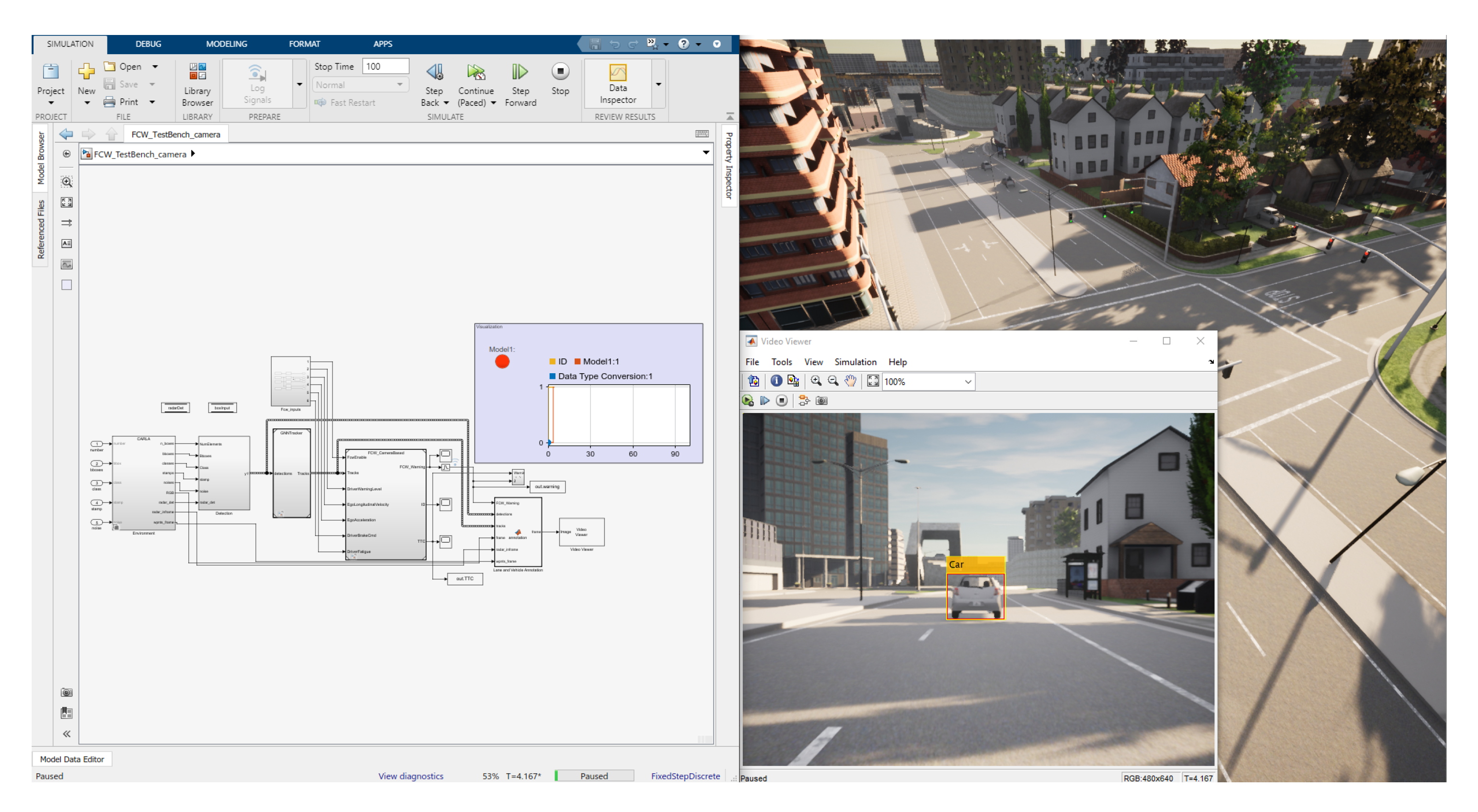
CARLA has a python-based core with embedded physics simulation which is capable of generating realistic measurements. In order to retrieve reliable sensor data, the simulation is carried out in synchronous fashion between the two environments; in particular, Simulink acts as a client by sending simulation commands to CARLA, acting as a server, which replies with the new generated measurements. In order to link the two environments a series of API have been implemented to create a communication between matlab-based Simulink and python-based CARLA cores. Figure 2 shows a screen capture of the proposed platform during a use case. In the case of the FCW feature the raw RGB frames are required, which are generated, at 30 fps, by a camera attached to a moving vehicle, mounted behind the windshield. The raw frames are the input to the algorithm introduced in Section 2.
The driving scenarios designed in CARLA are those defined in the safety assist assessment protocol by EuroNCAP [32], namely:
  • Car-to-Car Rear Stationary (CCRS): A collision in which a vehicle travels toward a stationary leading vehicle;
  • Car-to-Car Rear Moving (CCRM): A collision in which a vehicle travels towards a slower vehicle moving at constant speed;
  • Car-to-Car Rear Braking (CCRB): A collision in which a vehicle travels towards a braking vehicle.
All the scenario are repeated with varied vehicle velocities and lateral overlap ranging from 50 % to + 50 % , as defined by the protocol procedures. To demonstrate proof of concept, two exemplary scenarios will be shown, namely a CCRS with the ego vehicle traveling at v = 50 km/h with a starting distance of around d = 67 m, and a CCRM with the ego vehicle traveling at v = 50 km/h, the leading vehicle traveling at v = 20 km/h with a starting distance of around d = 30 m. Moreover, a quantitative comparison is performed with respect to the latest literature results, see [18], in which the authors proposed a similar CNN-based solution. Nonetheless the risk estimation index takes into account a single frame bounding box, resulting in velocity-independent information.
Figure 3 shows the numerical results in the first driving scenario (CCRS). Namely, the estimated TTC and the real one are compared in Figure 3a in order to assess the accuracy of the algorithm. Due to the constant relative velocity between the two vehicles, the TTCs decrease linearly with time. While the oscillations are in the estimated TTC, no false positives are reported in all the CCRS scenarios. Furthermore, only a small constant percentage error bias can be appreciated, essentially due to the constant distance between the forward facing camera, mounted behind the windshield, and the front bumper of the car, where the actual TTC is evaluated. Note that this bias varies with the distance to the forward obstacle, so it could be compensated by its estimation, which is currently not embedded in our particular design; it is the object of our next research work. Figure 3b shows the warning activation which occurs as soon as the estimated TTC goes below the threshold, chosen as 2.1 s. The comparison in Figure 3b discloses that by taking into account multiple frames a more accurate warning can be issued. Indeed a warning issued around T T C 1 s could not be enough to avoid a collision. Figure 4 shows the numerical results for the CCRM scenario and, as expected, the TTC trend is similar to the previous case. Note that the inaccuracies at high distances do not worsen the performances of the system, in fact no false positives are reported. Finally, Figure 4b shows the activation signal for the FCW for the CCRM case, along with the comparison with [18]. The outcome is very similar to the CCRS case.

4. Experimental Validation

In-vehicle experiments were carried out to validate the whole design. The camera-based algorithm was deployed on a NVIDIA Jetson AGX Xavier Developer board equipped with 8 CPU cores, 512 GPU cores and 32 GB of RAM. The hardware platform is able to achieve the 30 fps for real time purposes. The application was developed using the open source YoloV3 implementation available at [33] for the object detection component. This implementation is particularly convenient for embedded deployment because it uses CUDA and cuDNN for the fastest CNN inference on GPU cores. The remaining steps were implemented in MATLAB/Simulink at first for rapid prototyping, finally auto-generating C code through the Embedded Coder toolbox. Finally, the C++ OpenCV library [34] was used for visualization purposes during tests. The camera used is an HDR 2MP Starlight Camera, which uses an Omnivision Sensor. The combination of the high dynamic range, up to 120 dB, and the ultra low light technology allows the camera to capture images in difficult light conditions, thus enabling the FCW logic even during nights or inside tunnels [35]. It uses an electronic rolling shutter and a 58° field of view lens with fixed focus. Finally, it is connected to the NVIDIA board through the USB protocol. Clearly, more robust solutions can be deployed by fusing the camera signals with additional data coming from more accurate yet more expensive radar or lidar measurements.
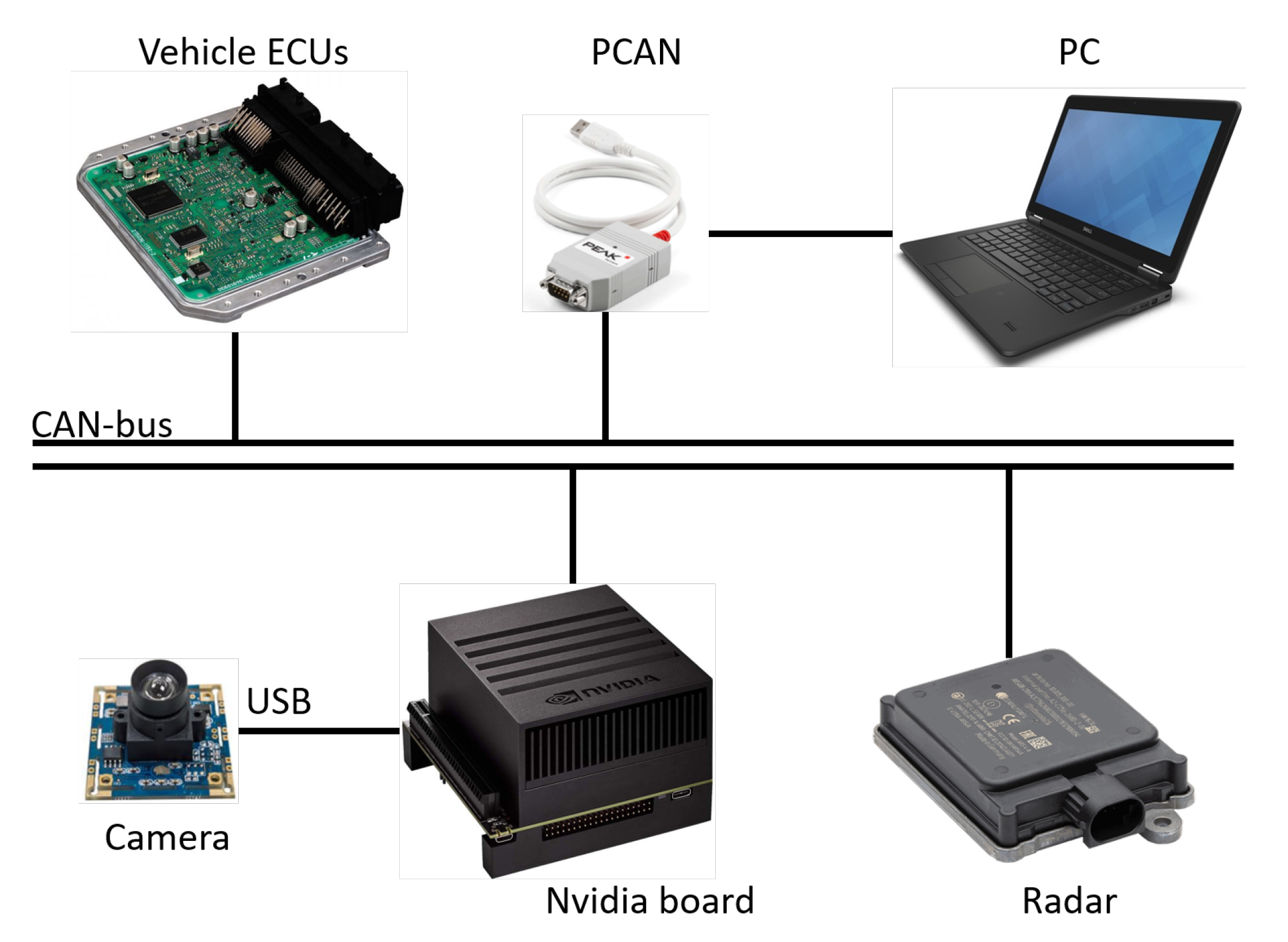
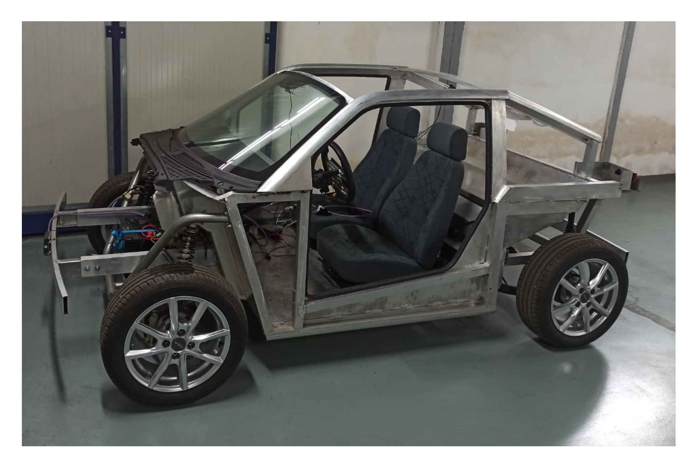
During MIL tests one can use the ground truth quantities, given by the simulator, to assess performances, whereas during experimental validation a second reliable source of information is required in order to make the same kind of assessment. In particular, an automotive RADAR was used, namely, ARS 404-21 from Continental, which can directly measure obstacle distances and relative velocities accurately; thus, it is possible to use Equation (1) to evaluate the TTC and make a comparison with the camera based in Equation (8). Finally, RADAR messages and warning activation signals, along with other vehicle data of interest, were collected from the vehicle CAN-bus using a PCAN-USB by PEAK System. Figure 5 shows the chosen hardware architecture and Figure 6 shows the electric platform employed during in-vehicle experiments.
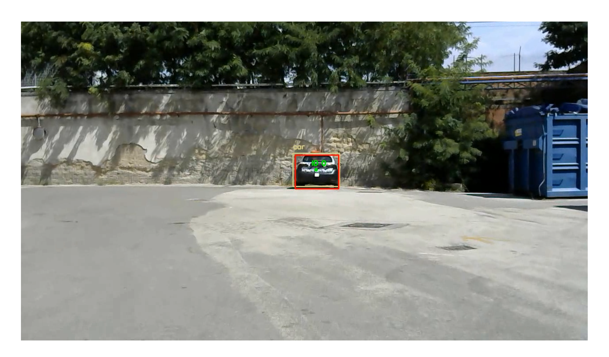
The driving scenario is the well-known EuroNCAP, which is one of the standard driving cycles for validation. In the CCRS scenario the following vehicle starts accelerating until it reaches around v = 30 km/h, moving towards a stationary vehicle. The FCW system emits a sound alarm when the TTC is lower than a threshold, which was set to 2.45 s during the tests. A test should be considered successful if the FCW algorithm generates an alert in a proper time, to brake the ego-vehicle and avoid the impact with the forward obstacle (see Figure 7 where an exemplary frame extracted from a recorded video of the CCRS scenario is shown).
Experimental results are disclosed in Figure 8, where the comparison between the estimated TTC based on camera information and the one based on expensive high-accuracy high-performance on-board radar are also shown (see Figure 8a). Results confirm that the performance obtained by the camera is comparable to the one achievable with the radar, so confirming the effectiveness of the approach for low-end commercial cars; moreover, no false positives or false negatives were reported during the experimental tests, as reported in Figure 8c.

5. Conclusions

In this paper a forward collision warning system is presented which leverages a deep convolutional neural network based on sensing data from an on-board forward camera. Moreover, it is shown that, by resorting to the scale change between consecutive frames, it is viable to rule out the error coming from camera calibration, making the system more robust with respect to camera mounting angle.
A general model-based virtual-testing platform has been designed to perform model-in-the-loop tests in a safe manner, exploitable even for more complex active safety systems. The numerical and experimental analysis show that the system is capable of promptly warning the driver if a collision is about to occur by replicating the EuroNCAP safety test assessments. Despite using a low-cost monocular camera for sensing, the overall architecture is accurate enough, at least in the TTC range of interest, i.e., below 3 (s). As prescribed by Euro NCAP protocol, we have extensively tested our design, not only experimentally, but also numerically by randomly varying the scenario conditions, thus verifying that the typical false/true warning rate requirements [36] are fulfilled. Results showed no false positives in all the appraised scenarios. Moreover, the employment of a state of the art deep CNN enhances the performances of the latest literature results. Future work will involve the investigation on estimation of the obstacle distance leveraging a mono or stereo camera, along with the implementation of more complex traffic and driving scenarios.

Author Contributions

Conceptualization, methodology and supervision, M.T., L.N. and G.F.; software, validation and formal analysis N.A. and F.M.; writing—original draft preparation, N.A.; writing—review, editing and visualization, L.N., F.M., M.T. and G.F. All authors have read and agreed to the published version of the manuscript.

Funding

This research was funded by the Italian Ministry of Economic Development (MISE)’s Fund for the Sustainable Growth (F.C.S) under grant agreement (CUP) B61B19000410008, project KINEBRAIN (“Key INteraction among Entertainment and BRAIN”).

Institutional Review Board Statement

Not applicable.

Informed Consent Statement

Informed consent was obtained from all subjects involved in the study.

Data Availability Statement

No new data were created or analyzed in this study. Data sharing is not applicable to this article.

Conflicts of Interest

The authors declare no conflict of interest.

Abbreviations

The following abbreviations are used in this manuscript:
FCW         Forward Collision Warning
TTCTime To Collision
CNNConvolutional Neural Network
YOLOYou Only Look Once
SSDSingle Shot Detector
FPNFeature Pyramid Network
mAPmean Average Precision
MTTMulti Target Tracker
GNNGlobal Nearest Neighbour
CUDACompute Unified Device Architecture
CPUCentral Processing Unit
GPUGraphics Processing Unit
RAMRandom Access Memory
MILModel-In-the-Loop
CARLACAR Learning to Act
CCRSCar-to-Car Rear Stationary
CCRMCar-to-Car Rear Moving
CCRBCar-to-Car Rear Braking
RGBRed Green Blue
RADARRAdio Detection And Ranging
LIDARLaser Detection and Ranging
EuroNCAPEuropean New Car Assessment Programme

References

  1. WHO. Global Status Report on Road Safety. 2018. Available online: https://www.who.int/publications-detail/global-status-report-on-road-safety-2018 (accessed on 1 July 2021).
  2. USDOT. Early Estimate of Motor Vehicle Traffic Fatalities for the First 9 Months of 2019. Available online: https://crashstats.nhtsa.dot.gov/Api/Public/ViewPublication/812874#:~:text=A%20statistical%20projection%20of%20traffic,as%20shown%20in%20Table%201 (accessed on 1 July 2021).
  3. Petrillo, A.; Pescapé, A.; Santini, S. A Secure Adaptive Control for Cooperative Driving of Autonomous Connected Vehicles in the Presence of Heterogeneous Communication Delays and Cyberattacks. IEEE Trans. Cybern. 2021, 51, 1134–1149. [Google Scholar] [CrossRef] [PubMed]
  4. Di Vaio, M.; Fiengo, G.; Petrillo, A.; Salvi, A.; Santini, S.; Tufo, M. Cooperative shock waves mitigation in mixed traffic flow environment. IEEE Trans. Intell. Transp. Syst. 2019, 20, 4339–4353. [Google Scholar] [CrossRef]
  5. Santini, S.; Albarella, N.; Arricale, V.M.; Brancati, R.; Sakhnevych, A. On-Board Road Friction Estimation Technique for Autonomous Driving Vehicle-Following Maneuvers. Appl. Sci. 2021, 11, 2197. [Google Scholar] [CrossRef]
  6. Castiglione, L.M.; Falcone, P.; Petrillo, A.; Romano, S.P.; Santini, S. Cooperative Intersection Crossing Over 5G. IEEE/ACM Trans. Netw. 2021, 29, 303–317. [Google Scholar] [CrossRef]
  7. Di Vaio, M.; Falcone, P.; Hult, R.; Petrillo, A.; Salvi, A.; Santini, S. Design and experimental validation of a distributed interaction protocol for connected autonomous vehicles at a road intersection. IEEE Trans. Veh. Technol. 2019, 68, 9451–9465. [Google Scholar] [CrossRef]
  8. Raphael, E.L.; Kiefer, R.; Reisman, P.; Hayon, G. Development of a Camera-Based Forward Collision Alert System. SAE Int. J. Passeng. Cars Electron. Electr. Syst. 2011, 4, 467–478. [Google Scholar] [CrossRef]
  9. Liu, J.F.; Su, Y.F.; Ko, M.K.; Yu, P.N. Development of a Vision-Based Driver Assistance System with Lane Departure Warning and Forward Collision Warning Functions. In Proceedings of the 2008 Digital Image Computing: Techniques and Applications, Canberra, ACT, Australia, 1–3 December 2008; pp. 480–485. [Google Scholar]
  10. Kuo, Y.C.; Pai, N.S.; Li, Y.F. Vision-based vehicle detection for a driver assistance system. Comput. Math. Appl. 2011, 61, 2096–2100. [Google Scholar] [CrossRef] [Green Version]
  11. Cui, J.; Liu, F.; Li, Z.; Jia, Z. Vehicle localisation using a single camera. In Proceedings of the 2010 IEEE Intelligent Vehicles Symposium, La Jolla, CA, USA, 21–24 June 2010; pp. 871–876. [Google Scholar]
  12. Salari, E.; Ouyang, D. Camera-based Forward Collision and lane departure warning systems using SVM. In Proceedings of the 2013 IEEE 56th International Midwest Symposium on Circuits and Systems (MWSCAS), Columbus, OH, USA, 4–7 August 2013; pp. 1278–1281. [Google Scholar]
  13. Kim, H.; Lee, Y.; Woo, T.; Kim, H. Integration of vehicle and lane detection for forward collision warning system. In Proceedings of the 2016 IEEE 6th International Conference on Consumer Electronics—Berlin (ICCE-Berlin), Berlin, Germany, 5–7 September 2016; pp. 5–8. [Google Scholar]
  14. Liu, M.; Jin, C.B.; Park, D.; Kim, H. Integrated detection and tracking for ADAS using deep neural network. In Proceedings of the 2019 IEEE Conference on Multimedia Information Processing and Retrieval (MIPR), San Jose, CA, USA, 28–30 March 2019; pp. 71–76. [Google Scholar]
  15. Mulyanto, A.; Borman, R.I.; Prasetyawan, P.; Jatmiko, W.; Mursanto, P. Real-Time Human Detection and Tracking Using Two Sequential Frames for Advanced Driver Assistance System. In Proceedings of the 2019 3rd International Conference on Informatics and Computational Sciences (ICICoS), Semarang, Indonesia, 29–30 October 2019; pp. 1–5. [Google Scholar]
  16. Lim, Q.; He, Y.; Tan, U.X. Real-Time Forward Collision Warning System Using Nested Kalman Filter for Monocular Camera. In Proceedings of the 2018 IEEE International Conference on Robotics and Biomimetics (ROBIO), Kuala Lumpur, Malaysia, 12–15 December 2018; pp. 868–873. [Google Scholar]
  17. Nava, D.; Panzani, G.; Savaresi, S.M. A Collision Warning Oriented Brake Lights Detection and Classification Algorithm Based on a Mono Camera Sensor. In Proceedings of the 2019 IEEE Intelligent Transportation Systems Conference (ITSC), Auckland, New Zealand, 27–30 October 2019; pp. 319–324. [Google Scholar]
  18. Hardt, W.; Rellan, C.; Nine, J.; Saleh, S.; Surana, S.P. Collision Warning Based on Multi-Object Detection and Distance Estimation. 2021; p. 68. Available online: https://www.researchgate.net/profile/Shadi-Saleh-3/publication/348155370_Collision_Warning_Based_on_Multi-Object_Detection_and_Distance_Estimation/links/5ff0e41ca6fdccdcb8264e2c/Collision-Warning-Based-on-Multi-Object-Detection-and-Distance-Estimation.pdf (accessed on 1 July 2021).
  19. Srinivasa, N.; Chen, Y.; Daniell, C. A fusion system for real-time forward collision warning in automobiles. In Proceedings of the 2003 IEEE International Conference on Intelligent Transportation Systems, Shanghai, China, 12–15 October 2003; Volume 1, pp. 457–462. [Google Scholar]
  20. Tang, C.; Feng, Y.; Yang, X.; Zheng, C.; Zhou, Y. The Object Detection Based on Deep Learning. In Proceedings of the 2017 4th International Conference on Information Science and Control Engineering (ICISCE), Changsha, China, 21–23 July 2017; pp. 723–728. [Google Scholar]
  21. Girshick, R.; Donahue, J.; Darrell, T.; Malik, J. Rich feature hierarchies for accurate object detection and semantic segmentation. In Proceedings of the IEEE Conference on Computer Vision and Pattern Recognition, Columbus, OH, USA, 23–28 June 2014; pp. 580–587. [Google Scholar]
  22. Redmon, J.; Farhadi, A. YOLOv3: An Incremental Improvement. arXiv 2018, arXiv:1804.02767. [Google Scholar]
  23. Liu, W.; Anguelov, D.; Erhan, D.; Szegedy, C.; Reed, S.; Fu, C.Y.; Berg, A.C. Ssd: Single shot multibox detector. In European Conference on Computer Vision; Springer: Cham, Switzerland, 2016; pp. 21–37. [Google Scholar]
  24. Sanchez, S.A.; Romero, H.J.; Morales, A.D. A review: Comparison of performance metrics of pretrained models for object detection using the TensorFlow framework. IOP Conf. Ser. Mater. Sci. Eng. 2020, 844, 012024. [Google Scholar] [CrossRef]
  25. Bar-Shalom, Y.; Li, X.R. Multitarget-Multisensor Tracking: Principles and Techniques; YBS publishing: Storrs, CT, USA, 1995; Volume 19. [Google Scholar]
  26. Konstantinova, P.; Udvarev, A.; Semerdjiev, T. A study of a target tracking algorithm using global nearest neighbor approach. In Proceedings of the International Conference on Computer Systems and Technologies (CompSysTech’03), Sofia, Bulgaria, 19–20 June 2003; pp. 290–295. [Google Scholar]
  27. Munkres, J. Algorithms for the assignment and transportation problems. J. Soc. Ind. Appl. Math. 1957, 5, 32–38. [Google Scholar] [CrossRef] [Green Version]
  28. Del Carmen, D.J.R.; Cajote, R.D. Assessment of Vision-Based Vehicle Tracking for Traffic Monitoring Applications. In Proceedings of the 2018 Asia-Pacific Signal and Information Processing Association Annual Summit and Conference (APSIPA ASC), Honolulu, HI, USA, 12–15 November 2018; pp. 2014–2021. [Google Scholar]
  29. Kalman, R.E. A New Approach to Linear Filtering and Prediction Problems. J. Basic Eng. 1960, 82, 35–45. [Google Scholar] [CrossRef] [Green Version]
  30. Stein, G.P.; Mano, O.; Shashua, A. Vision-based ACC with a single camera: Bounds on range and range rate accuracy. In Proceedings of the IEEE IV2003 Intelligent Vehicles Symposium. Proceedings (Cat. No.03TH8683), Columbus, OH, USA, 9–11 June 2003; pp. 120–125. [Google Scholar]
  31. Dosovitskiy, A.; Ros, G.; Codevilla, F.; Lopez, A.; Koltun, V. CARLA: An open urban driving simulator. In Proceedings of the Conference on Robot Learning, Mountain View, CA, USA, 18 October 2017; pp. 1–16. [Google Scholar]
  32. EURONcap. Safety Assist Protocol. 2020. Available online: https://cdn.euroncap.com/media/56143/euro-ncap-aeb-c2c-test-protocol-v302.pdf (accessed on 1 July 2021).
  33. Darknet YoloV3 Github Repository. Available online: https://github.com/AlexeyAB/darknet (accessed on 1 July 2021).
  34. OpenCV Project Referecence. Available online: https://opencv.org/ (accessed on 1 July 2021).
  35. Knoll, P.M. HDR Vision for Driver Assistance; Springer: Berlin/Heidelberg, Germany, 2007; pp. 123–136. [Google Scholar]
  36. NHTSA. Vehicle Safety Communications—Applications (VSC-A) Final Report: Appendix Volume 1 System Design and Objective Test. 2011. Available online: https://www.nhtsa.gov/sites/nhtsa.gov/files/811492b.pdf (accessed on 1 July 2021).
Figure 1. YOLOv3 Network Architecture [22].
Energies 14 04872 g001
Figure 2. Screenshot of the co-simulation platform. On the right the CARLA server; on the left the Simulink implementation of the proposed algorithm supported by the communication APIs between the two components.
Energies 14 04872 g002
Figure 3. Simulation results, through MIL testing, in the CCRS scenario. (a) Time-history of the estimated time-to-collision, T ^ , and of the real one, T. The warning threshold is shown as a constant horizontal line; (b) time-history of the forward collision warning activation.
Energies 14 04872 g003
Figure 4. Simulation results, through MIL testing, in the CCRM scenario. (a) Time-history of the estimated Time-To-Collision, T ^ , and of the real one, T. The warning threshold is shown as constant horizontal line (b) Time-history of the Forward Collision Warning activation.
Energies 14 04872 g004
Figure 5. In-vehicle hardware architecture.
Energies 14 04872 g005
Figure 6. Electric vehicle used for experimental validation.
Energies 14 04872 g006
Figure 7. Example of captured image frames from CCRS scenario video.
Energies 14 04872 g007
Figure 8. Results of the experimental validation in a CCRS scenario. (a) Time-history of the estimated Time-To-Collision, T ^ , compared to the estimated through the RADAR sensor, T. The warning threshold is shown as a constant horizontal line. (b) Time-history of the vehicle speed. (c) Time-history of the Forward Collision Warning activation.
Energies 14 04872 g008
Publisher’s Note: MDPI stays neutral with regard to jurisdictional claims in published maps and institutional affiliations.