1. Introduction
The transition from a traditional grid to a microgrid with the combination of DG units is happening at a rapid pace around the world [
1]. Despite the great economic and environmental well-being provided by renewable DG, it has its own drawbacks, such as difficulties in power system operation, control, and security [
2]. Voltage fluctuations, power fluctuations, and power quality problems are all caused by non-dispatchable renewable energy sources’ intermittent behavior [
3]. The microgrid’s DG units are still energized to satisfy local demand in an island state, but the microgrid is electrically disconnected from the utility grid [
4]. As a result, island identification in a microgrid is unavoidable in order to fulfill its role. Furthermore, in the case of unscheduled islanding, the system’s behavior may be unpredictable [
5]. IEEE 1547-2003 and IEEE 1547a-2014 guidelines recommend that DG be disconnected within 2
s [
4]. The microgrid may be disconnected from the rest of the network for an isolated service in the event of a recurrent fault in the utility [
6]. If a fault occurs inside the microgrid and the circuit breaker is opened, the islanding detection algorithm can work to isolate the smallest possible faulted region of the microgrid [
7]. Furthermore, the islanding detection algorithm should have the ability to distinguish between true islanding and transient events such as the initiation and clearing of a fault in a nearby feeder [
8]. Local and remote islanding detection techniques (IDTs) have been described in the literature [
9]. IDTs are divided into two categories based on local measurements: passive and active techniques. When the power difference between the DG and the load is very low or zero, the passive methods fail [
10]. The advantage of the active technique is the minimum non-detecting zone (NDZ), but it decreases the power quality [
11,
12,
13,
14,
15,
16,
17,
18]. The combination of active and passive techniques is able to decrease the NDZ and also maintain the desired power quality, but the algorithm is unable to differentiate between the events [
7,
19,
20,
21]. An effective islanding detection algorithm should be able to detect all possible islanding scenarios, but most schemes currently focus only on grid-side faults [
22].
An effective and fast monitoring system using systemic principal component analysis was proposed in [
19]. However, their scheme would have necessitated longer computational time. In [
23], they proposed a multi-functional fault detection algorithm by using PMU data of voltage angle with dynamic monitoring and supervision. Pattern recognition techniques for island events based on transient signals have been discussed [
24,
25], but the implementation of this proposed system is extremely difficult. Utilizing PMU data for detecting islanding events has been proposed [
26,
27]. In [
26], they used frequency difference to detect islanding events, whereas [
27] used the change in phase angles, but those algorithms are not effective for the match frequency condition due to the minimal voltage and frequency excursion in the match frequency condition.
For detecting islanding events, decision tree (DT) approaches show higher accuracy performance [
28,
29]. The supervisory control and data acquisition (SCADA) system is a very popular approach for detecting islanding events but is unable to feedback accurately due to the conveying delay and also the higher investment required for the installment [
30]. An islanding detection scheme using the voltage angle difference between two PMUs was discussed in [
31], where detection time showed better performance but the under-frequency and over-frequency islanding condition performance was absent from their algorithm. Differentiating the islanding operation with the normal operation using PMU voltage angle was discussed in [
32], where a simulation was conducted in the IEEE 30 bus system, but they did not consider the transient fault event. In [
33,
34], they proposed a probabilistic component analysis-based islanding detection method. The proposed method showed faster detection without false triggers but the scheme was collapsed detect when phase angle and frequency are well matched during islanding events. A voltage angle and current angle-based islanding detection algorithm was proposed in [
35,
36], where they lessened the false triggers but did not show any performance analysis on the match frequency islanding condition. A voltage magnitude-based islanding detection method was proposed in [
37,
38], but the proposed method was unable to detect islanding of the minimal power exchange condition due to the local detection scheme. In [
39], they calculated the current flow through the breaker, and in that case, an island was detected before opening the breaker. However, in that case transmission loss was considered as the DG islanding conditions. In [
40], they used a ridgilet probabilistic neural network to detect the islanding and were able to detect islanding but did not consider the transient faults.
The goal of this research was to figure out the island thresholds with a minimum time and distinguish islands from transient faults. The challenges of this research work were (1) the phase angle value of the different DG islanding conditions being located in dissimilar regions, (2) setting a single threshold that would be applicable for the under-frequency and over-frequency islanding conditions, and (3) distinguishing between the real islanding event and the transient fault. This research work proposes a new slip angle and acceleration angle-based island detection threshold setting method.
The proposed island threshold setting method is different from other schemes because it is able to distinguish between the real islanding threshold and the transient fault threshold by a single time step. According to other literature, most islanding detection schemes do not distinguish transient faults from the island event, which means that detecting a transient fault as an island event is possible. However, in reality, a transient fault is not island event. However, the studies that attempted to address this issue discovered a longer island detection time as a result of the inappropriate threshold setting. Therefore, this research work identified that specific research gap and worked to set the appropriate island detection thresholds, which ensure event differentiation with faster island detection. The remainder of the paper is organized as follows: The methodology is explained in
Section 2. The simulation of the system is in
Section 3, and the results discussion is in
Section 4.
2. Methodology
2.1. Slip Angle and Acceleration Angle
The proposed islanding detection threshold determining methodology focuses on the slip angle and acceleration angle. This scheme calculates the slip angle based on the rate of change of the angle difference of the DG and the utility bus with respect to the time, and the acceleration angle is the rate of change of the slip angle with respect to the time. This proposed novel slip angle and acceleration angle theory was motivated by [
41,
42].
where Δ
v is the voltage angle difference between the DG and the utility bus. However, the slip angle and acceleration angle come from the PMU voltage angle data.
2.2. Proposed Island Detection Threshold Setting Method
To detect island events in a timely manner, a substantial part involves setting the threshold precisely to detect islands as well as differentiate the transient faults. Generally, if the threshold is not set properly the scheme cannot detect islanding events or may require more time.
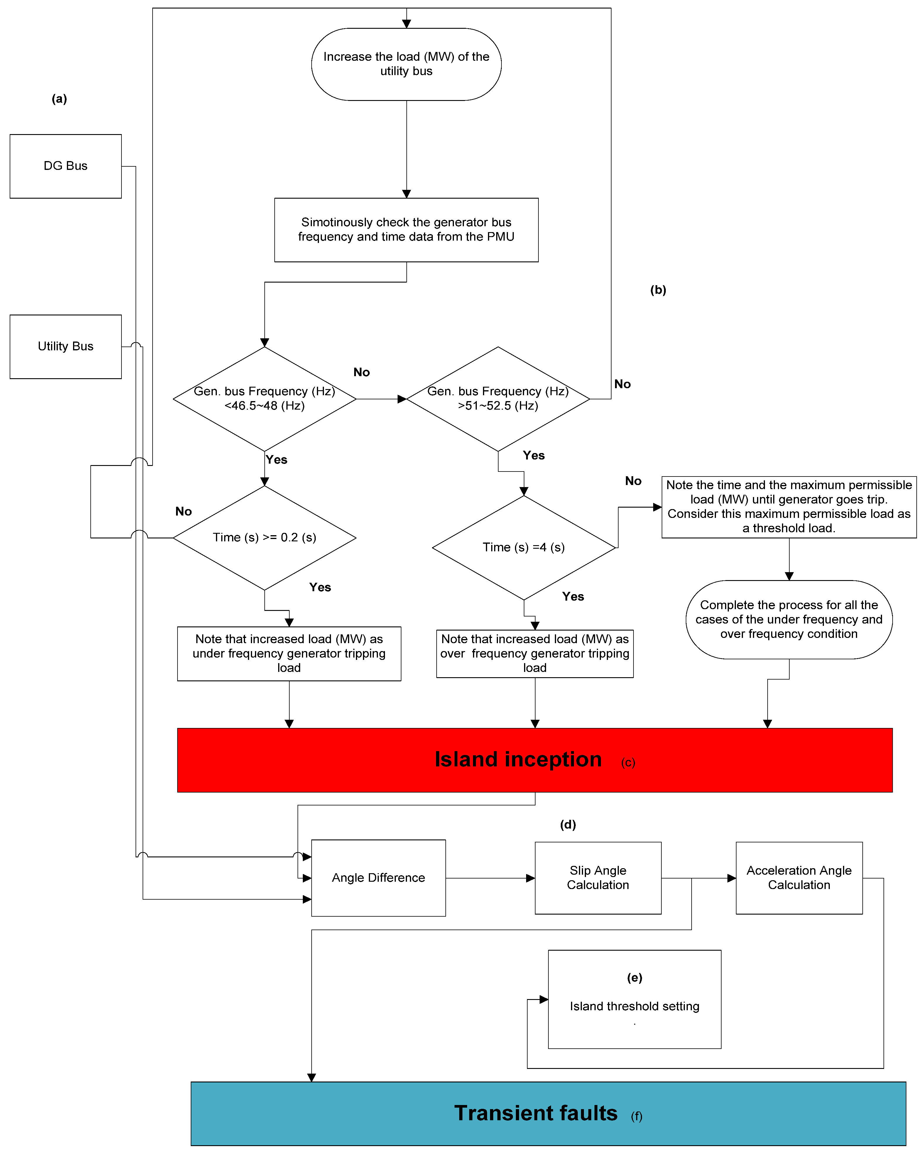
Figure 1 shows the proposed threshold setting method of the islanding event and transient fault. There are five units in this proposed method: bus, determining load threshold, island inception, threshold value calculation, and threshold setting.
Details of the proposed islanding detection threshold setting methodology are as follows:
- (a)
Bus
It is critical to know which buses we can use for our calculation when determining the island threshold setting.
Figure 1 depicts two buses, one of which is a DG bus and the other a utility bus. We used a modified IEEE 30 bus system in this research work, and there were two DG buses: Bus 11 (33 KV) and Bus 13 (33 KV). In this research work, we considered Bus 13 (33 KV), and for the utility buses, Bus 3 (KV).
- (b)
Determining Load Threshold
Different load values result in different network conditions. From
Figure 1, it is evident that the load could be increased until the generator loses its synchronism [
43]. However, the under-frequency condition allows the generator to trip 0.2 s at a frequency less than 46.5~48 Hz, and the over-frequency condition allows the generator to trip 4 s at a frequency greater than 51~52.5 Hz [
42]. Only a permissible load can be determined for under-frequency and over-frequency conditions from there.
- (c)
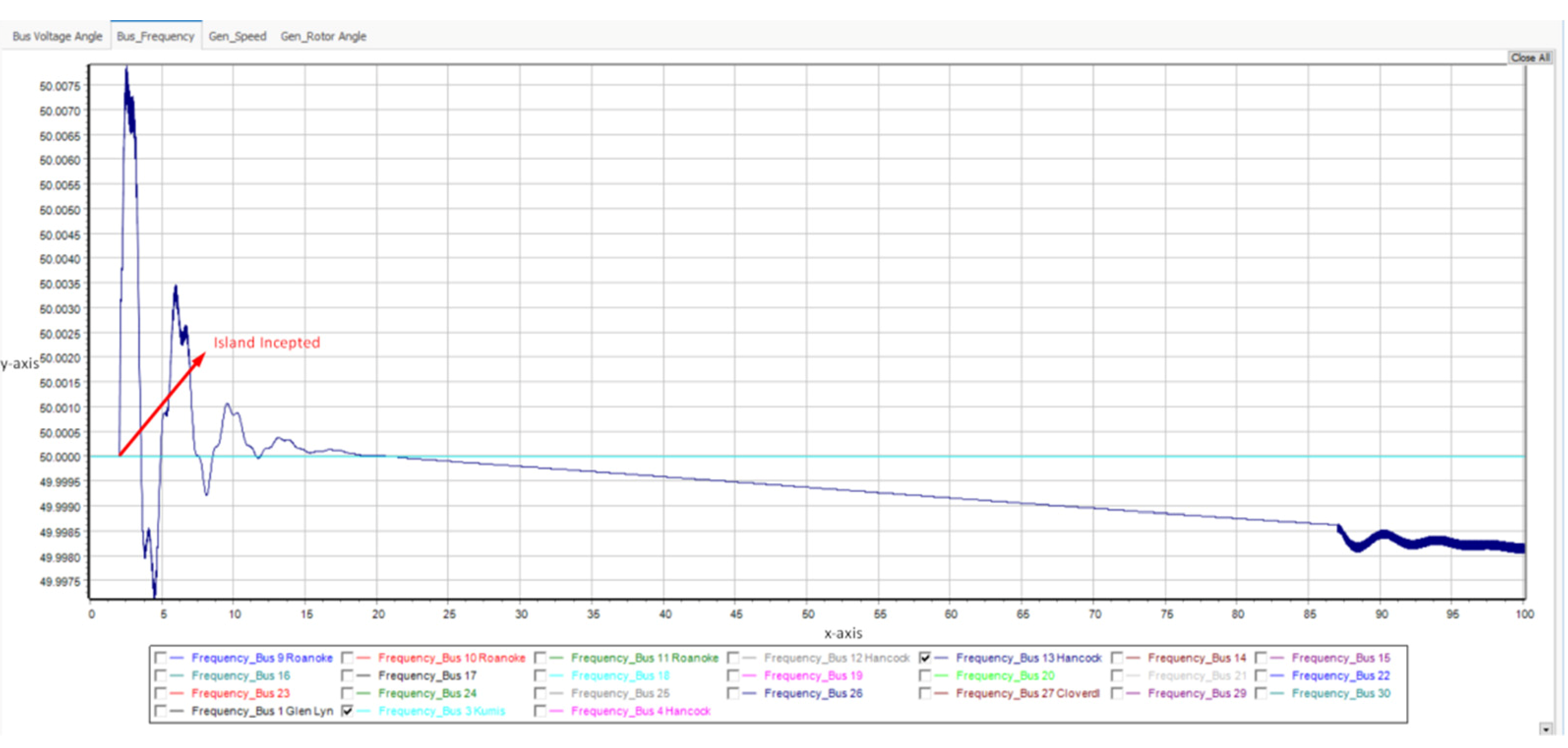
Island Inception
Islanding occurs when generators and loads are disconnected from the main system but remain energized [
4]. Voltage and frequency fluctuate, resulting in power quality degradation and synchronization issues on the utility grid.
- (d)
Threshold Value Calculation
This section consists of three important calculation segments: the angle difference, slip angle, and acceleration angle. From the PMU voltage angle data, the voltage angle difference between DG bus and utility bus is calculated, then using (1) and (2) the slip angle and acceleration angle value are calculated.
- (e)
Island Threshold Setting
Once all of the PMU slip angle and acceleration angle data from (d) have been calculated, a common threshold value can be created that will be applicable to all cases of under-frequency and over-frequency island conditions.
- (f)
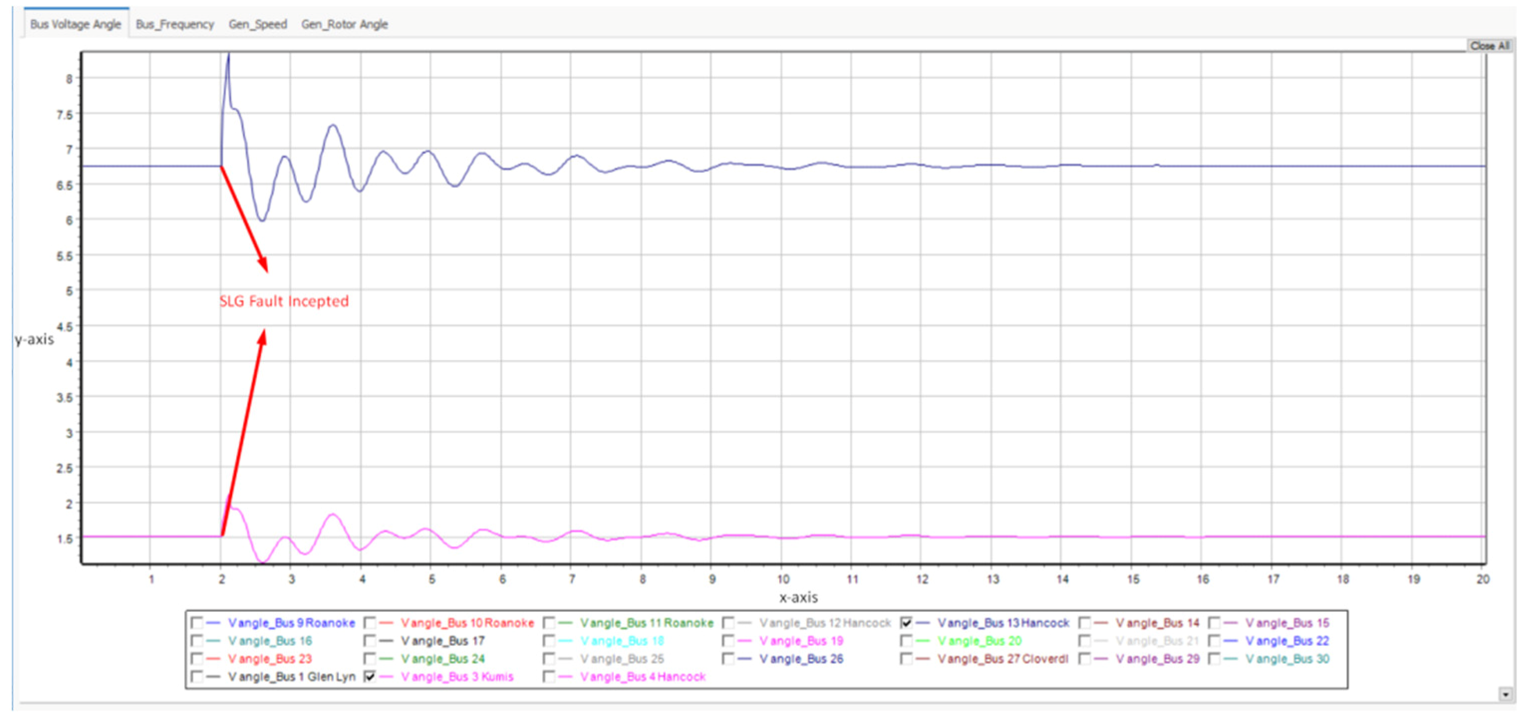
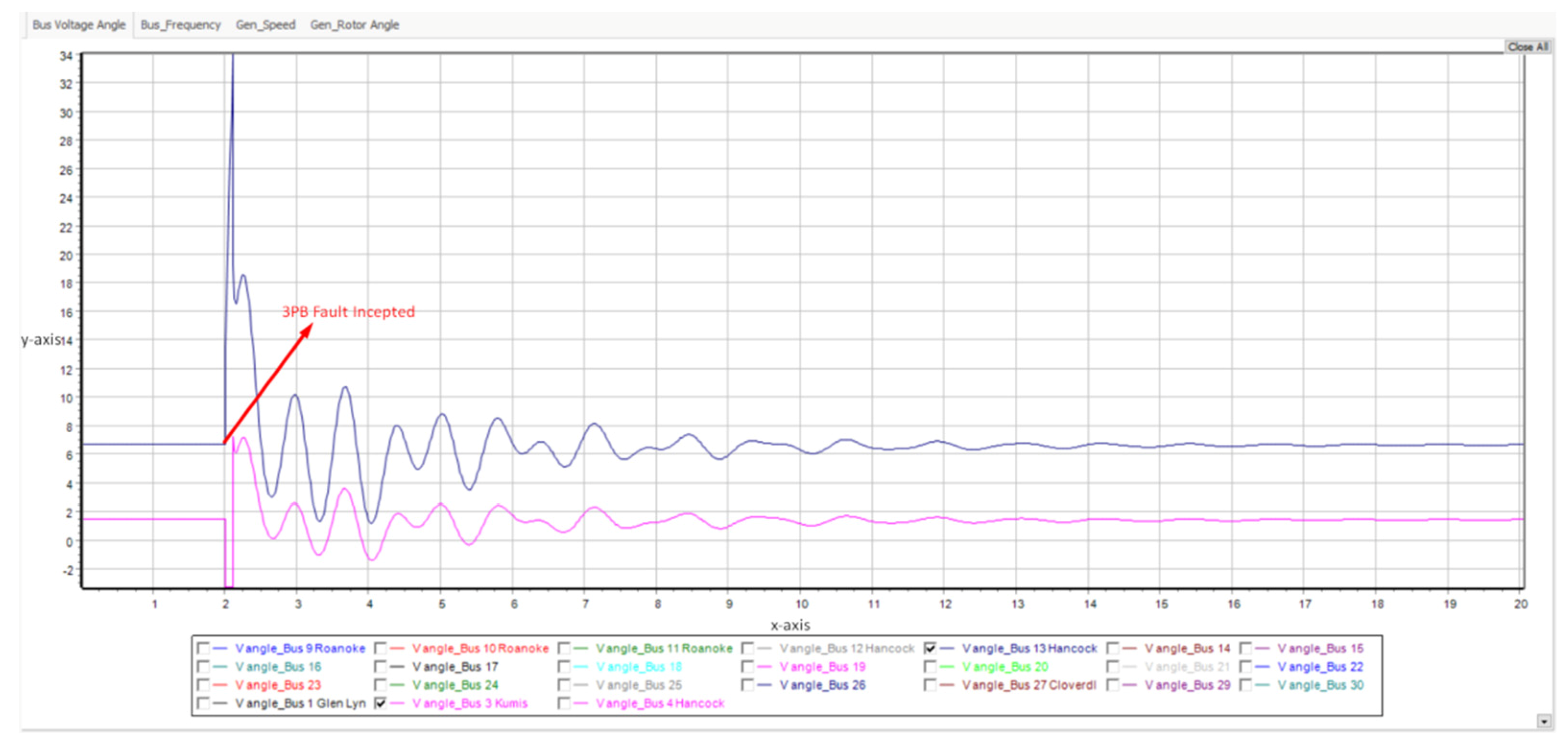
Transient Faults
A substantial segment of this proposed methodology is to distinguish transient faults from the island. To figure out the transient faults threshold, the following steps are carried out:
Step 1. Perform fault current analysis at the utility buses.
Step 2. Find out the highest fault current bus.
Step 3. Create transient faults at the highest fault current bus by allowing 100 ms as fault clearing time according to [
44].
Step 4. Get the voltage angle data of the transient faults.
Step 5. Calculate the slip angle from the voltage angle data using Equation (1).
Step 6. Take the maximum slip angle value from that 100 ms region as a transient fault threshold.
3. Simulation
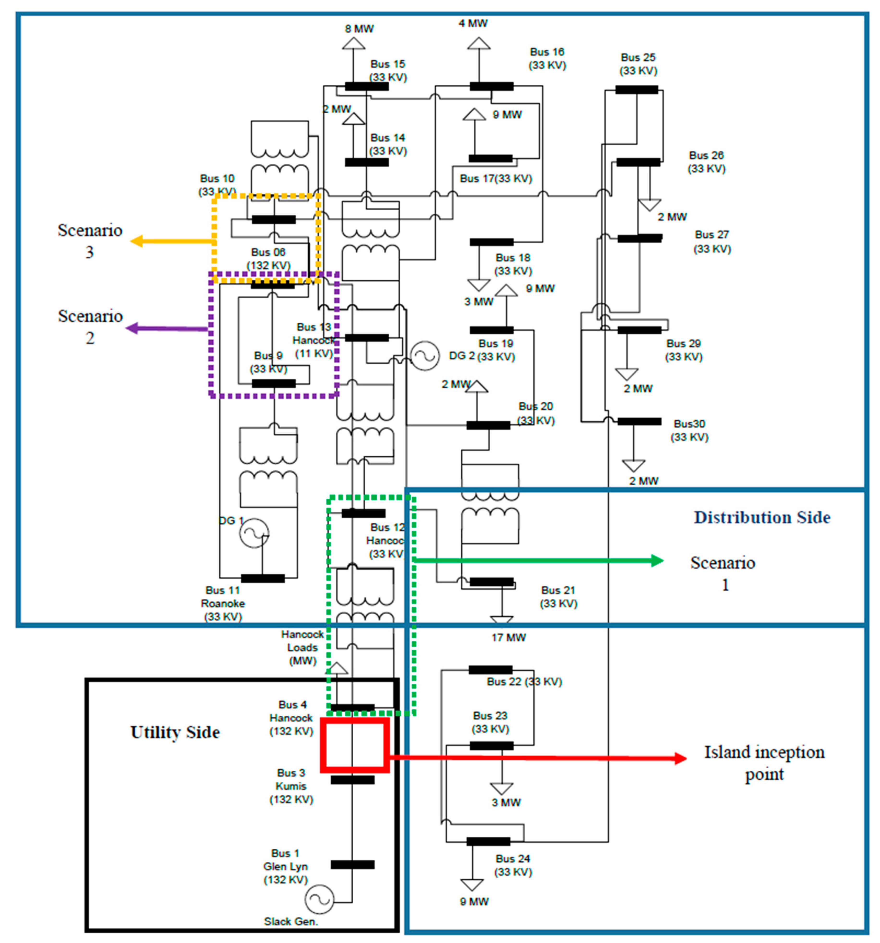
This section discusses details of the test power system model. In
Figure 2 there are three scenarios in this test system network. Details of the test system scenarios are as follows.
Scenario 1
The Bus 4 (132 KV) to Bus 12 (32 KV) interconnection point is connected, where Scenario 2 and Scenario 3 will both remain open. In this scenario Bus 4 (132 KV) imports power from Bus 12 (33 KV) to feed the connected load.
Scenario 2
In this case Scenario 1 is opened and the DG side is connected with the Bus 6 (132 KV). Here the interconnection point between Bus 6 (132 V) and Bus 9 (33 KV) is connected and Bus 9 (132 KV) exports power to Bus 6 (132 KV) to feed the Bus 4 (132 KV) connected load.
Scenario 3
In this scenario interconnections of Scenario 1 and Scenario 2 are both opened. Here the interconnection point between Bus 6 (132 KV) and Bus 10 (33 KV) is connected and Bus 10 (132 KV) exports power to Bus 6 (132 KV) to feed the Bus 4 (132 KV) connected load.
Table 1 and
Table 2 present the parameters of the simulated power system model and data preparation. PMU data was prepared using a PowerWorld simulator.


 ,
, 


